

Page 1

D 900 AP
D 1000 AP
D 1000 APG
OPERATOR’S
MANUAL
ENGLISH
ORIGINAL MANUAL
Page 2

Page 3

D 900 AP
D 1000 AP
D 1000 APG
Above chassis number 63163011
ORIGINAL MANUAL
Page 4

Page 5
D 900 AP / D 1000 AP / D 1000 APG
3
Thank you for choosing this AUSA dumper model which offers the best levels of
performance, safety and working comfort. Remember that you are the key to maintaining
these characteristics. Correct use of the dumper will enable you to take full advantage of
the features it has to offer.
You should read and understand this Manual before operating the dumper. Its purpose
is to provide instructions for those persons in contact with the vehicle and especially for
the vehicle operator . Its content will help you to better understand the AUSA dumper, and
teach all you need to know about starting the vehicle, driving techniques, maintenance
and care, designed uses of the vehicle and safety instructions to be followed.
AUSA cannot be held responsible for any damages caused by the improper use of the
vehicle.
Please contact your official AUSA agent or dealer if you have any queries, complaints or
orders for spare parts.
For further information you may call, write, FAX or email to:
AUSA Center, S.L.U.
P.O.B. 194
08243 MANRESA (Barcelona), SPAIN
Tel. 34-938 747 552 / 938 747 311
Fax 34-938 736 139 / 938 741 211 / 938 741 255
E-mail: [email protected]
Web: http://www.ausa.com
AUSA is continually improving its products and reserves the right to make such
improvements without incurring any obligation to make changes to dumpers previously
sold. Therefore, claims cannot be made based on the data, illustrations and descriptions
set forth in this manual.
Use only original AUSA spare parts. Only thus can you guarantee that the dumper will
continue to give the same level of technical performance as when purchased.
No changes should be made to the dumper without prior authorisation from the
manufacturer.
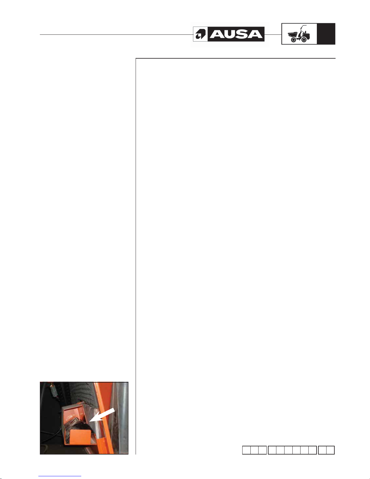
Keep this manual in the document holder situated under the right engine cover (fig. 1).
(fi g. 1)
MOP 141212 02
Foreword
Page 6

D 900 AP / D 1000 AP / D 1000 APG
4
Index
Designed use of the dumpers ................................................................................ 5
Special safety messages ........................................................................................ 6
Identification plates and labels ............................................................................... 11
Specifications .......................................................................................................... 12
How to identify your dumper ................................................................................... 16
Controls instruments equipment ............................................................................. 17
Operating the dumper ............................................................................................. 22
Break in period ........................................................................................................ 26
Before starting the dumper ..................................................................................... 27
Transporting the dumper ........................................................................................ 28
Liquids and lubricants ............................................................................................. 31
Special procedures ................................................................................................. 34
Periodic maintenance operations ........................................................................... 36
Maintenance chart .................................................................................................. 57
Greasing points ....................................................................................................... 59
Electric diagram ...................................................................................................... 60
Hydraulic diagram D 900 AP / D 1000 AP .............................................................. 66
Hydraulic diagram D 1000 APG .............................................................................. 67
EC declaration of conformity ................................................................................... 68
Page 7

D 900 AP / D 1000 AP / D 1000 APG
5
Designed use
of the dumpers
The dumpers have been designed and manufactured for the transport of loose
materials, (mortar, cement, sand, gravel and rubble or materials from demolitions).
Any other use should be considered outside of the intended use and therefore improper .
Close adherence to the operation, maintenance and repair conditions specified by the
manufacturer is essential for good use of this vehicle.
Driving, maintenance and repair of the dumper must only be entrusted to duly trained
personnel, who have the required tools and know the intervention and safety procedures
relating to the dumper.
Health and safety at work and accident prevention standards should be respected during
all transport, maintenance or repair operations. Current legislation must be adhered to
(Highway Code) when driving on public roads.
AUSA shall not be responsible for any possible harm caused by any modification carried
out on the dumper without their express authorisation.
Improper use
Improper use is understood to be the use of the dumper in such a way that it does not
meet with the criteria and instructions of this manual and in such a way that said use may
cause harm to persons or items.
The following are some of the most frequent and dangerous instances of improper use:
- Transporting people in the cargo box.
- Failing to comply scrupulously with the instructions for use and maintenance set
out in this manual.
- Overloading
- Working on unstable, unconsolidated ground or on the edge of ditches and
trenches.
- Using accessories and equipment for purposes other than those they are
designed for.
- Using accessories and equipment not manufactured or authorised by AUSA.
Page 8
D 900 AP / D 1000 AP / D 1000 APG
6
(fi g. 3) (fi g. 2) (fi g. 1)
AUSA manufactures their dumpers in accordance with demands for intrinsic
protection, as established in current law for countries of the European Economic
Community, against dangers of any kind, which may present a risk to health or life,
whenever the machine is used and maintained in accordance with these directives. Any
hazard caused by improper use, not in compliance with these instructions or others
specifically provided with the dumper will be responsibility of the user and not AUSA.
This section gives instructions on how the dumper must be used as per that contained
in the 2004/42/EC Machine Safety Directive.
As a driver, think about...
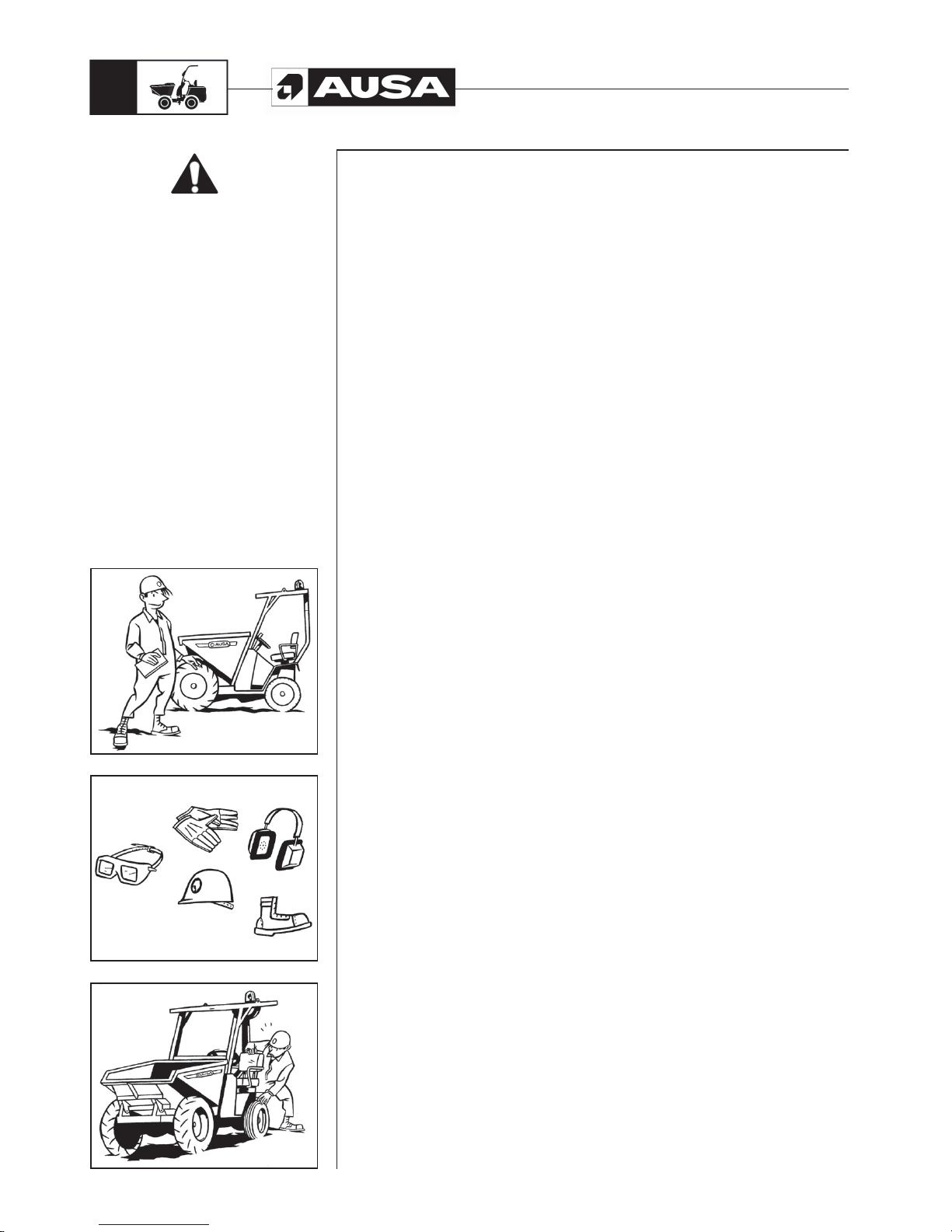
• Before you begin using a dumper that you are not yet familiar with, you should read
this operator manual carefully and consult your superior if you have any doubts (fig.
1). The dumper should only be used by authorised and properly trained personnel.
• Make sure that you are issued with all the necessary protective gear to enable you
to carry out your work safely, for instance: hard hat, ear protectors, warm clothes,
reflective equipment, safety glasses, etc. (fig. 2).
• The operation of the dumper whilst wearing bracelets, chains, loose clothing, long
hair which is not tied back, etc. is not recommended due to the risk of being caught
in controls, rotating parts, cracks, etc.
Depending on the work area, remember....
• If there is a risk of fire or explosion in the working area, either because of goods
stored or because of possible fluid or gas leaks, check that the dumper is fitted with
a sufficient degree of fire protection.
• If you have to work in closed spaces, make sure that the area is well ventilated in
order to prevent the excessive build-up of exhaust fumes. Always turn the engine off
when it is not needed.
• T o drive the dumper on public roads, all necessary approvals and licenses must be
obtained in accordance with the current country legislation, also incorporating the
signalling and safety elements included in the legislation.
• Current legislation does not require the mounting, as standard, of a structure for
protection from falling objects. However, if you must use the dumper in areas that
manifest a risk of this type, the same legislation indicates that you must equip the
machine with said structure.
• Use of the dumper without lighting is permitted in full daylight or in areas which are
sufficiently lit.
When starting up the dumper (fig. 3)
• Before starting work with the dumper, clean up any possible oil or fuel which may
have leaked, clean and remove any grease from your hands and the soles of your
shoes and remember to check the following items:
• Tyre pressure and tread condition.
• Check brake functioning.
• Check for any leaks in the hydraulics, fuel and cooling systems, etc.
• Check that all protectors, covers and safety end stops are correctly positioned and
properly attached.
• Check that there are no cracks or other structural defects visible to the naked eye.
• Check the correct operation of all controls.
• Check the following fluid levels:
- fuel
- brake fluid
- Hydraulic oil
- Coolant
• Check the seatbelts and their mountings are in good condition and properly fixed.
Carefully inspect the condition of this device paying special attention to:
- Cuts or threading on the belt
- Wear or damage to anchor points
- Poor functioning of the seat belt buckle or the retracting roller
- Loose threads or poor stitching
• Check that all covers, locks and other safety elements are correctly positioned.
Special
safety
messages
Page 9
D 900 AP / D 1000 AP / D 1000 APG
7
(fi g. 4) (fi g. 3) (fi g. 2) (fi g. 1)
• Check the correct functioning of alarms and signalling devices (for example:
acoustic warning, obstruction indicator for the air admission filter, etc.)
• Check that all the information and safety advice plates on the dumper are clean and
in good condition.
• Check that the lighting and signalling system is clean and working properly
• Check battery connections and electrolyte level
• Adjust the seat position so that you are comfortable and can easily reach the
controls
• Do not start the engine or operate the controls unless you are seated in the cab.
• For your safety in the case of overturning, do not forget to correctly adjust and
fasten the seat belt.
• Keep the driving area clear of all objects or tools that could move about and might
obstruct a control and prevent you from carrying out a manoeuvre when required.
(fig. 1)
• Although not recommended, if you use a spray with ether to start the dumper in low
temperatures, do so in well ventilated areas, do not smoke during the operation and
spray small amounts.
• These pressurised containers should be stored away from heat sources, and when
empty they should neither be thrown on fires nor crushed as there may be a risk of
explosion.
• Always stop the engine before refuelling and never smoke during the process
Do not mix gasoline or alcohol with the fuel
When operating the dumper, do not forget... (fig. 2, 3, 4)
• If you notice any anomaly while using the dumper, inform your superior or
maintenance service immediately.
• Keep hands, feet and the whole body in general inside the area provided for the
operator.
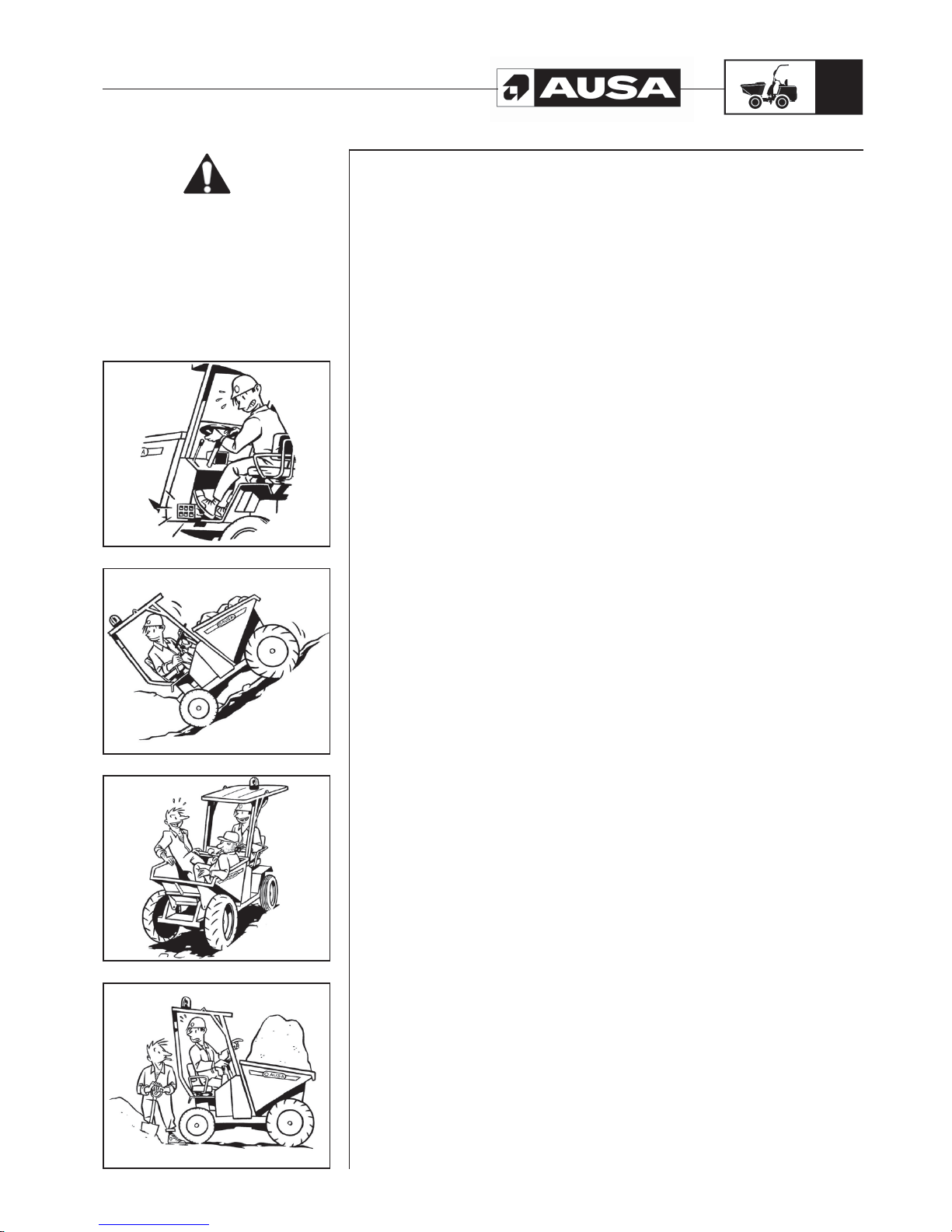
• Pay special attention to work on slopes, move slowly , avoid being situated crosswise
and do not operate slopes which exceed the recommended gradient. A slope
within the recommended gradient does not mean that this slope manoeuvred on
with absolute safety under any load, terrain or handling conditions. Descend slopes
in reverse gear, with the load, therefore, in the most stable direction. (fig. 2)
• It is not recommended to operate on slopes greater than 20% where the ground is
wet or 30% where it is dry.
• Never descend a slope with the transmission lever in neutral.
• Give way to any pedestrians you might come across while driving.
• The dumper must not be used to transport people, other than the driver, unless
adequate seats have been provided (fig. 3).
• Do not overload the dumper. Carry out manoeuvres gently, especially when
changing direction on slippery ground.
• Ensure that you have good visibility of the track, if the load obstructs visibility, drive
in reverse gear and increase precautions (fig. 4).
• When approaching a crossroads with poor visibility, slow down, sound your horn
and move forwards slowly in accordance with your level of visibility.
• The speed of the dumper should be adjusted at all times to the work conditions and
the area where it is being carried out. Regularly driving the machine at maximum
speed may represent a danger to the operator and to his or her surroundings.
Special
safety
messages
Page 10
D 900 AP / D 1000 AP / D 1000 APG
8
(fi g. 4) (fi g. 3) (fi g. 2) (fi g. 1)
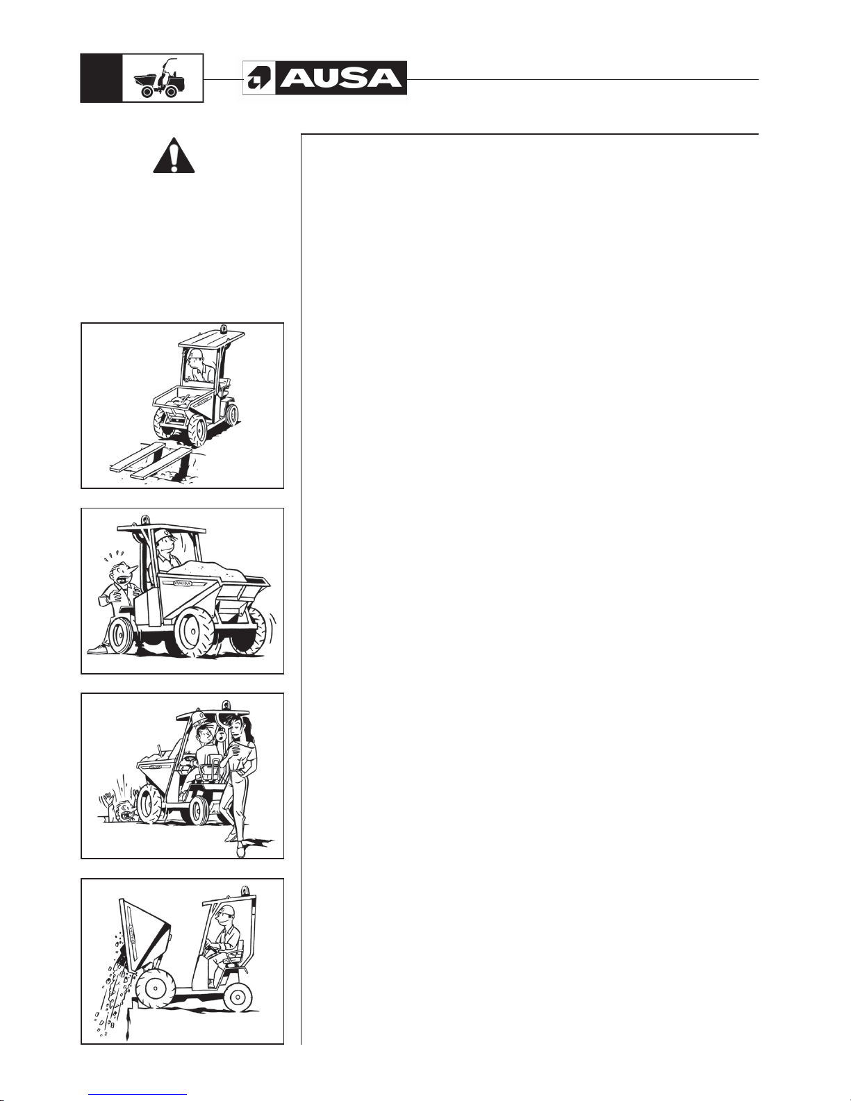
• Check that the resistance of the ground on which you are driving is sufficient for the
loaded dumper, in particular on access to bridges, embankments, slabbed areas,
loading areas, etc (fig. 1).
• Before reversing the dumper, the operator should check that doing so will not put at
risk either the machine itself or nearby people or objects. (fig. 2)
• Do not drive with the cargo box elevated.
• Do not activate two cargo box movements simultaneously.
• Keep your mind completely on the job in hand. The safety of both the driver and
others depends on the care taken when driving. (fig. 3)
• Depending on the ground, try to raise as little dust as possible while moving about.
• The dumper is not a machine designed for towing other dumpers. If this is
unavoidable, place a certain amount of load in the cargo box to ensure traction.
• Drive carefully and at a reduced speed; and if the tow load is not fitted with an inertia
brake, make sure that the brakes are strong enough for both the dumper mass and
that of the tow load.
• If the dumper has the possibility of two axle traction, consider that this must only be
connected when required for surmounting a sloping obstacle or a slippery surface.
Drive at a reduced speed in order to preserve the tyres and do not subject the
traction-steering unit to excessive workloads.
Take care when loading and unloading the dumper...
• Do not empty the contents of the cargo box near a bank which is not reinforced, and
unless there is a safety stop bar for the wheels at a safe distance from the edge. An
8cm side boarding cannot be considered an acceptable stopping device (fig. 4).
• When tipping the load of a dumper, the centre of gravity continually moves and
the condition of the ground and the prudence of the operator are essential for the
stability of the machine.
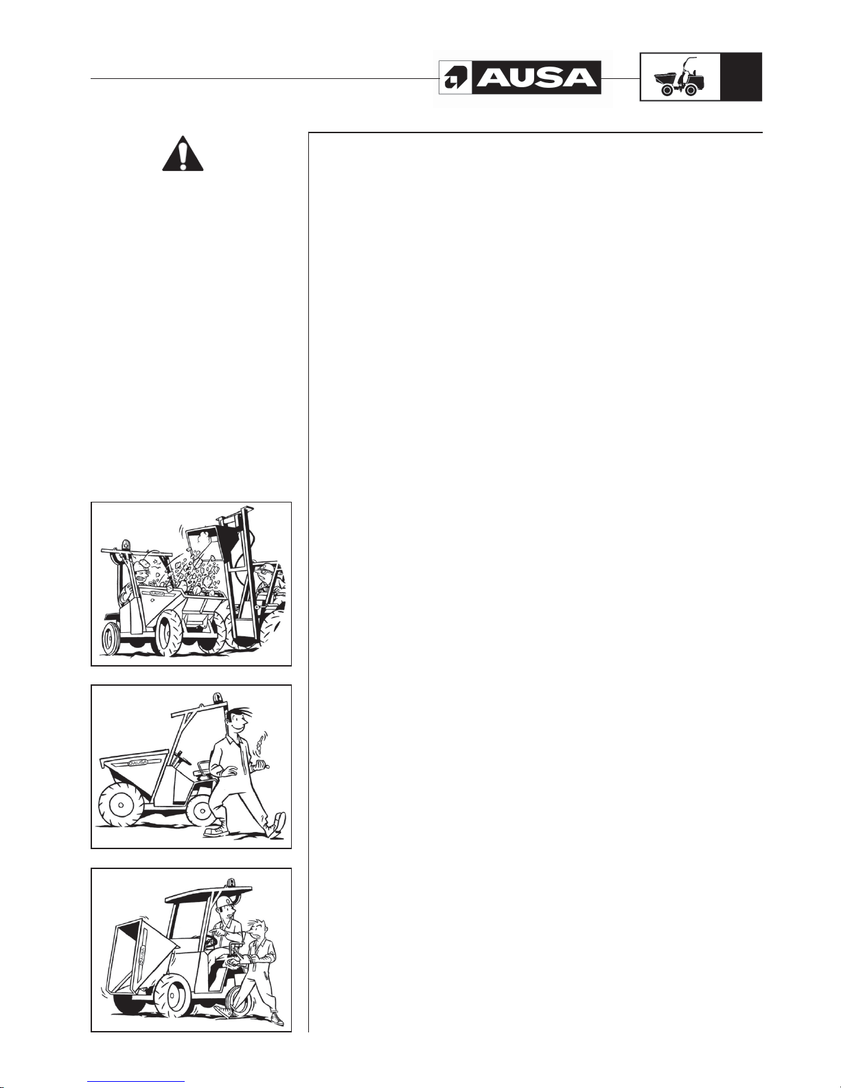
• When the dumper is loaded by shovel, crane or other similar external methods, the
driver must leave the cab. (fig.1 next page)
• Perform the unloading manoeuvre progressively, maintaining the stability of the
dumper.
Avoid transporting materials which would stick to the dumper (for example: clayey
loam) or that would get stuck in the dumper (for example: blocks of stone), as the
loss of control which may be produced in the tipping manoeuvre places the stability
of the dumper at risk.
Special
safety
messages
Page 11
D 900 AP / D 1000 AP / D 1000 APG
9
(fi g. 3) (fi g. 2) (fi g. 1)
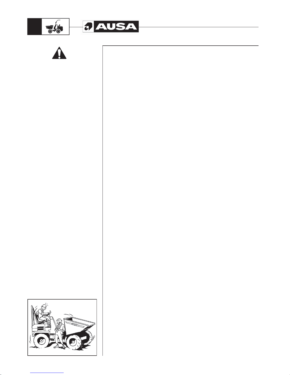
When leaving the vehicle....
• Turn the engine off and switch off the ignition. Place the cargo box in the horizontal
resting position (fig. 2).
• Place all controls in the neutral standby position.
• Put the parking brake on.
• Lock all mechanisms which impede use of the vehicle by unauthorised persons; the
starter circuit in particular, by removing the ignition key.
• If you must leave the dumper on a slope, in addition to putting the parking brake on,
immobilise the wheels with suitable chocks.
• Leave the dumper in areas specifically designated for this purpose, and not where it
prevents people from passing or blocks exits or access to stairways or emergency
equipment.
• As the dumper has an articulated chassis, when leaving it, always leave it in a
straight position.
Good conservation is a safety guarantee, so....
• Never stop carrying out dumper maintenance. Specialised personnel should be
assigned to this job, who are equipped with the necessary tools and appropriate
instructions.
Only authorised personnel should perform maintenance and repair work.
• Unless unavoidable, all attention to the dumper should be done with the engine
switched off, the cargo box unloaded, and all the immobilizing and locking devices
engaged.
• Some operations are easier done with the cargo box tipped in the unloading
position. Before doing so, precautions must be taken to prevent it from accidentally
tipping using the devices designed for this purpose which are provided in each
dumper model (fig. 3).
• Before disconnecting fluid systems, make sure there is no pressure in them and
take steps to avoid unexpected spills. Never use a flame to check fluid levels and
leaks.
• Regular checks should be carried out on the hydraulic system to detect any possible
leaks or misalignment on the safety valves which could lead to a risk situation.
• Regular checks should also be carried out on all those elements whose excessive
wear or ageing could lead to a risk situation, for example: hydraulic pipes, brake
linings, tyre restraining rings, etc.
• In the case of the roof or operator protection arch has suffered an impact that has
produced any permanent deformity, as this is a safety element it must therefore be
replaced for a new one.
• All identification, instruction and warning plates attached to the dumper must be
kept in a perfectly readable condition.
• Any modification which affects the capacity and safety of the dumper must be
authorised by the vehicle manufacturer or by a responsible manufacturer , modifying
where necessary the instruction manuals and plates.
• The manufacturer will not be held responsible for any incidents or accidents caused
by the use of non-original spare parts or by repairs carried out by unauthorised
workshops.
• When replacing tyres, ensure that they are the correct replacements and follow the
tyre manufacturer’s safety instructions. For safety reasons, split wheels must not be
used (those made of two rims bolted together).
• Lifting the dumper for handling or inspection should be carried out using the points
on the machine designed for this purpose, as indicated in this manual, and with
strong enough apparatus for this purpose. As the chassis is articulated, the frames
must first be joined to the belt designed for this purpose.
Special
safety
messages
Page 12
D 900 AP / D 1000 AP / D 1000 APG
10
(fi g. 1)
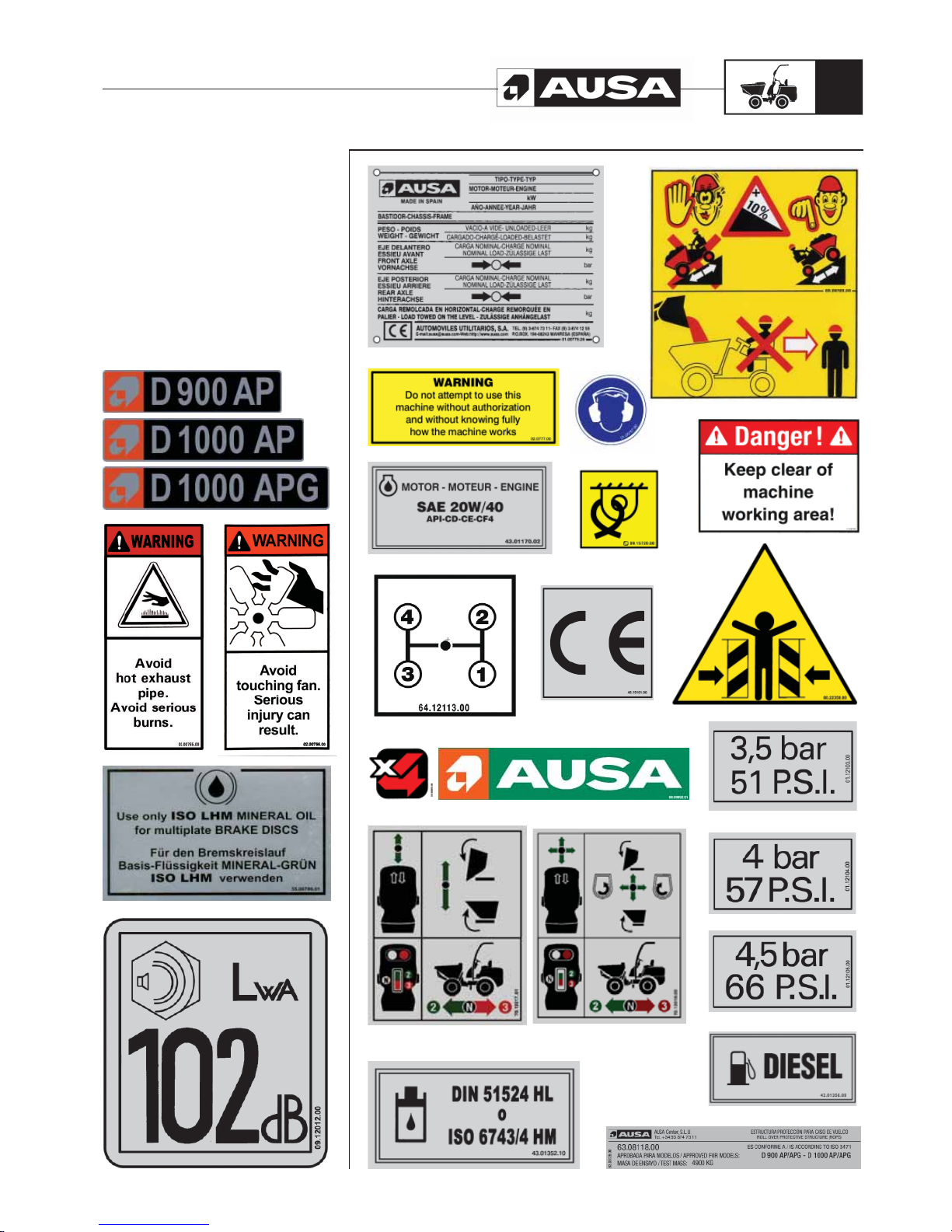
• If the dumper needs to be towed, use a tow bar whenever possible, or if none is
available, a cable that is strong enough for the job. In either case, it should be fixed
onto the point indicated by the manufacturer and the manoeuvre should be carried
out at a speed of no more than 10 Km/h.
When driving a towed dumper, pay attention to the position of your hands on the
steering wheel, to ensure that an unexpected turn of the wheel does not cause you
injury.
• Make sure that the towing dumper has a strong enough towing and braking
capability to be able to perform this operation.
• If the dumper needs to be transported on a truck platform:
- Ensure that only a minimum amount of fuel remains in the tank.
- Apply the brakes to the dumper.
- Apply chocks to the wheels and attach them to the truck bed.
- Anchor the machine firmly to the truck bed using slings or other methods to
prevent any kind of movement.
• When carrying out any repair work, make especially sure that the battery terminals
are protected, so that they cannot accidentally be shorted out by a tool, part, etc.
• As the chassis is articulated (articulated frame steering), before undertaking any
operation on the dumper , place the joining beam between the frames, in a way that
the articulations are immobilised (fig. 1)
• Before carrying out any electrical soldering work on the dumper, remove the electric
and electronic equipment in order to avoid possible damage to the installations.
• If the dumper to be towed is hydrostatically driven, before doing so, follow the
instructions indicated in this manual for the disconnection of the drive shaft,
therefore facilitating towing and eliminating any risk to the hydrostatic unit.
• When changing a tyre, make sure that it is fitted with the tread pattern facing the
right way.
• Before carrying out any work on the engine cooling system, wait for the temperature
of the coolant to drop enough for the coolant reservoir cap to be removed safely.
• In order to avoid allergic reactions and other hazards affecting the skin, replenishing
of fuel or other fluids should be carried out wearing protective gloves.
• Be environmentally friendly. When changing oil, fluids, tyres, batteries, etc., take the
used materials to the corresponding recycling centres.
If you handle or scrap silencers that contain mineral fibre based absorbent materials,
protect your skin with the appropriate gloves and clothing and take the materials to
approved disposal sites for this class of materials.
Similarly, at the end of the useful life of this vehicle, hand it to an authorised scrap
centre.
• Also, if concrete spills onto the road surface, remove it before it hardens.
ELECTROMAGNETIC COMPATIBILITY
• If the machine vehicle is used in areas where there are devices that are very sensitive
to electromagnetic emissions, make sure that they will not be affected by this.
Special
safety
messages
Page 13
D 900 AP / D 1000 AP / D 1000 APG
11
Identification
plates and labels
Page 14
D 900 AP / D 1000 AP / D 1000 APG
12
Diesel engine
Kubota V3800DI-T-E3B, water cooled diesel engine, four cylinder, four-stroke, electric
ignition with starter motor.
Power:
98,91 HP / 72,8 Kw at 2600 rpm according to SAE J 1995 Norm
Transmission
Torque converter with synchronised gearbox with 4 forward gears and 4 reverse gears
using an electro-hydraulic inverter. Epicyclical reduction axles at the differential output.
Traction
permanent 4x4
The inversion of the gears (forward/reverse) is done using an electric switch on the lower
part of the joystick handle on the right side of the seat.
When the direction is selected, the indication light in the form of an arrow pointing in the
corresponding direction is lit.
Steering
“ORBITROL” Hydraulic system, driven by a hydraulic cylinder which controls the chassis
articulation.
Work Pressure: 115 bar.
Brakes
Service Brake
Multiple disc oil filled sealed units
Hydraulically powered
Parking Brake
Multiple disc oil filled sealed units
Mechanically powered
Wheels
All four wheels are the same.
Wheel sizes: 500/60-22.5 (16PR)
Inflation pressure front wheels: See machine identification plate.
Inflation pressure rear wheels: See machine identification plate.
FRONT REAR
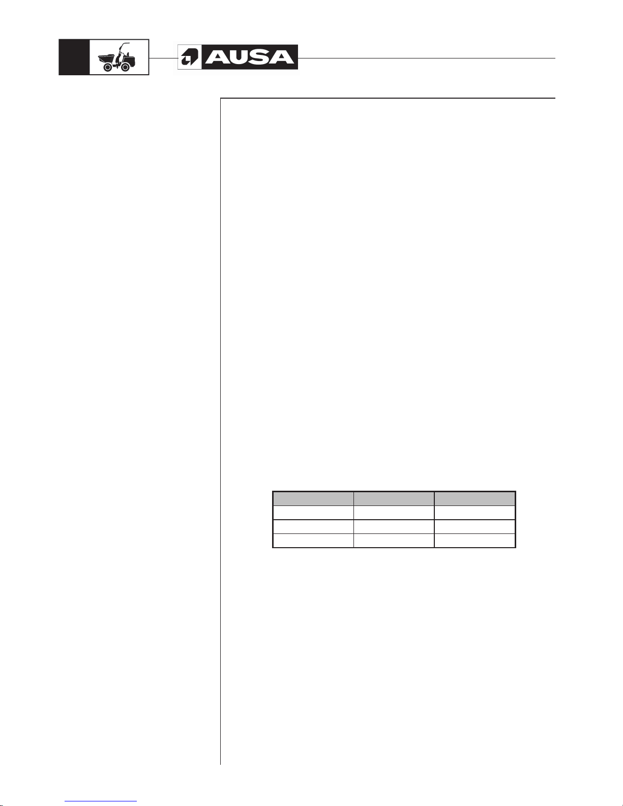
D 900 AP 57 P.S.I. 51 P.S.I.
D 1000 AP 66 P.S.I. 51 P.S.I.
D 1000 APG 66 P.S.I. 51 P.S.I.
Operation temperature
From -15ºC to 40ºC
Hydraulic Circuit
A 25cc gear pump coupled to the engine.
Control valves for bucket actuation:
D 900 AP / D 1000 AP models: Single spool monoblock control valve.
D 1000 APG models: Two spools monoblock control valve.
The pressure limit valve is set to 170 bar.
65 l. hydraulic oil tank
Specifications
Page 15

D 900 AP / D 1000 AP / D 1000 APG
13
Electrical Equipment
- Electrical starting motor of 3.0 Kw
- Battery 12V and 90 Ah. / 760 A
- 12 V / 60 A alternator
- Diesel preheating plugs
- Rotating beacon
- Horn
- Acoustic warning for reverse gear
Unladen weight (with full tanks). See machine identification plate.
D 900 AP: 4.700 Kg.
D 1000 AP: 4.760 Kg.
D 1000 APG: 4.990 Kg.
Load Capacity. See machine identification plate.
D 900 AP: 9.000 Kg.
D 1000 AP / D 1000 APG: 10.000 Kg.
Maximum Weight. See machine identification plate.
D 900 AP: 13.780 Kg.
D 1000 AP: 14.840 Kg.
D 1000 APG: 15.070 Kg.
Maximum width
2.480 mm.
Maximum gradient (fully loaded)
60%
Vibration and sound levels
Sound power level:
Warrantee sound power (according to 2000/14/EC sound emissions in the environment
by machinery for outdoor use):
• Lwa = 102 dB (A)
Sound pressure level on the operator’s site:
A weighted sound pressure in the operator’s ear measured (following norms ISO 6394):
• Lpa = 84 dB (A)
• Measurement uncertainty: 2,5 dB (A)
Vibration level produced by the machine:
Root-mean-square frequency-weighted, hand-arm vibration acceleration value:
< 2,5 m//s
2
Root-mean-square frequency-weighted, whole body vibration acceleration value:
< 0,5 m/s
2
Control panels
The controls, switches and warning lights are in the operators front protection panel,
along with the switches and warning lights for optional lighting equipment.
ROPS Protector Arch
Built in accordance with ISO 3471 Standards.
Specifications
Page 16
D 900 AP / D 1000 AP / D 1000 APG
14
External turning radius
5.950 mm.
Bucket box capacities (litres)
D 900 AP D 1000 AP D 1000 APG
WATER 2240 2440 2491
LEVEL 3665 3750 3941
HEAPED 5040 5225 5944
Optional Equipment
Officially approved lighting equipment
WARNING
The seat belt is an important part of this safety system and must always be
fastened before operating the dumper . F ailure to wear the seatbelt in the event
of an accidental tip over could result in serious injury or death by crushing
caused by the vehicle or the overhead protector itself.
Specifications
Page 17
D 900 AP / D 1000 AP / D 1000 APG
15
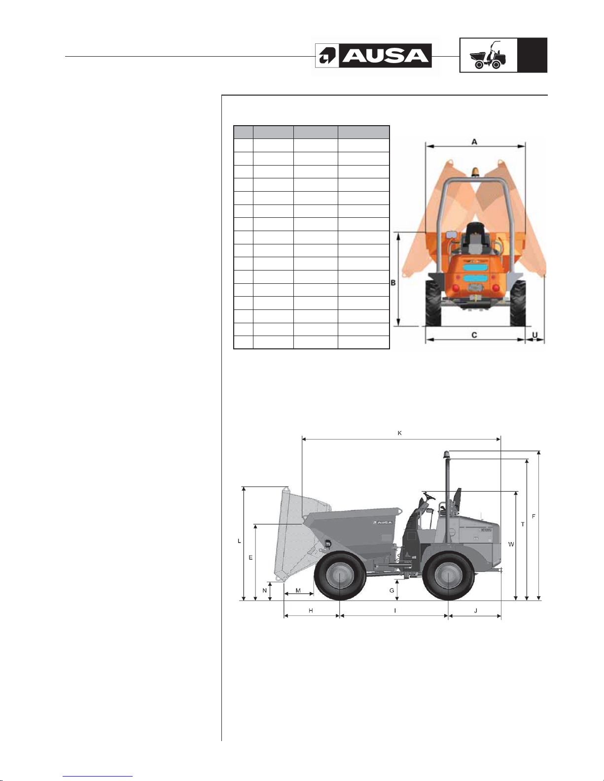
Machine Measurements (in mm)
D 900 AP D 1000 AP D 1000 APG
A 2480 2480 2480
B 2190 2380 2385
C 2440 2440 2440
E 1860 1820 1950
F 3530 3560 3560
G 490 490 490
H 1260 1260 1230
I 2450 2450 2450
J 1220 1220 1220
K 4518 4520 4990
L 2640 2710 3820
M 665 665 630
N 430 430 1100
T 3370 3370 3375
U - - 100
W 2550 2550 2550
Specifications
Page 18
D 900 AP / D 1000 AP / D 1000 APG
16
(fi g. 4) (fi g. 1)(fi g. 2)(fi g. 3)
IMPORTANT!
Please indicate model number, date of purchase and frame and serial number when
consulting AUSA or your dealer for any matter
Model, purchase date, chassis number and engine number. These details are marked
on the identification plate.
We recommend you make a record of these numbers in the spaces provided below for
handy reference and keep it in your files.
Dumper model: ....................................................................
Date of purchase:.................................................................
Frame number: .....................................................................
Engine number: ....................................................................
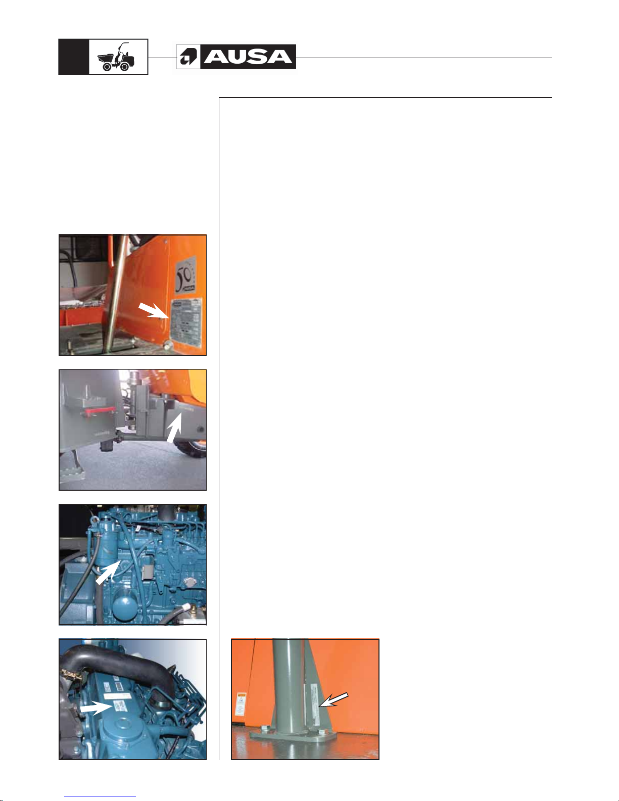
The machine’s identification plate (fig. 1) is located on the front part of the
engine protector (behind the gear stick). It includes the CE trademark.
The frame number (fig. 2) is marked on the front part of the right side of the
chassis.
The engine number (fig. 3 and 4) is marked on the left side of the block behind
the fuel filter and on a label on the upper part of the valve cover.
The ROPS arch homologation plate (fig. 5) is located in the lower right post
of the arch.
Main component identification plates
Identification plates for all components not manufactured by AUSA, such as: engines,
pumps, etc. are attached to the components themselves, in the positions where the
respective manufacturers originally fitted them.
How to identify
your dumper
(fi g. 5)
Page 19
D 900 AP / D 1000 AP / D 1000 APG
17
Controls
instruments
equipment
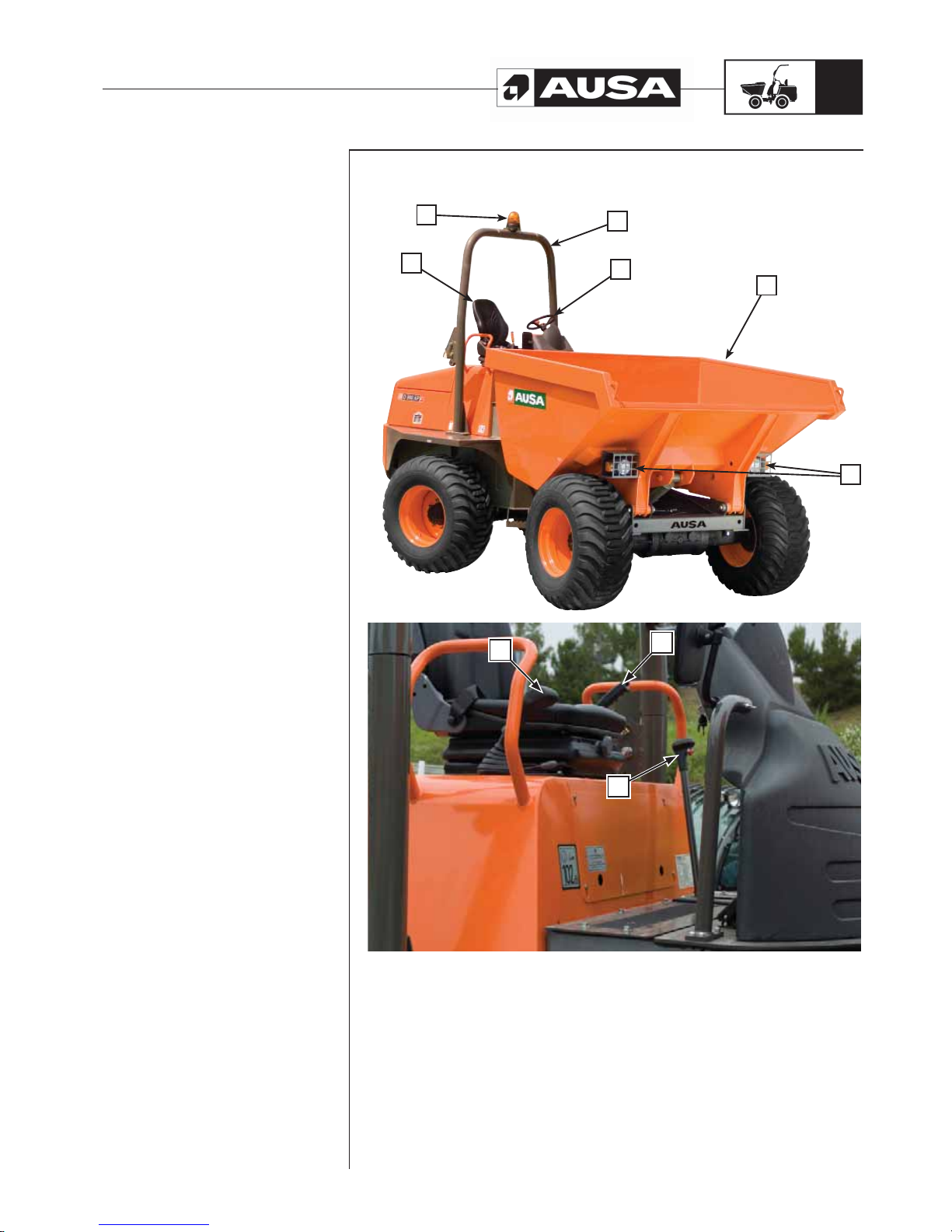
Terms such are right, left, front and rear, used in this Manual indicate the sides of the
vehicle from the driver’s seat looking forward.
Identification of the components
a- Protector arch
b- Operator’s seat with seatbelt
c- Rotating indicators
d- Cargo box
e- Joystick
f- Steering wheel
g- Gear stick
h- Parking Brake
i- Lights and signal lights (optional)
a
f
d
c
b
i
a
e
a
h
a
g
Page 20
D 900 AP / D 1000 AP / D 1000 APG
18
Controls
instruments
equipment
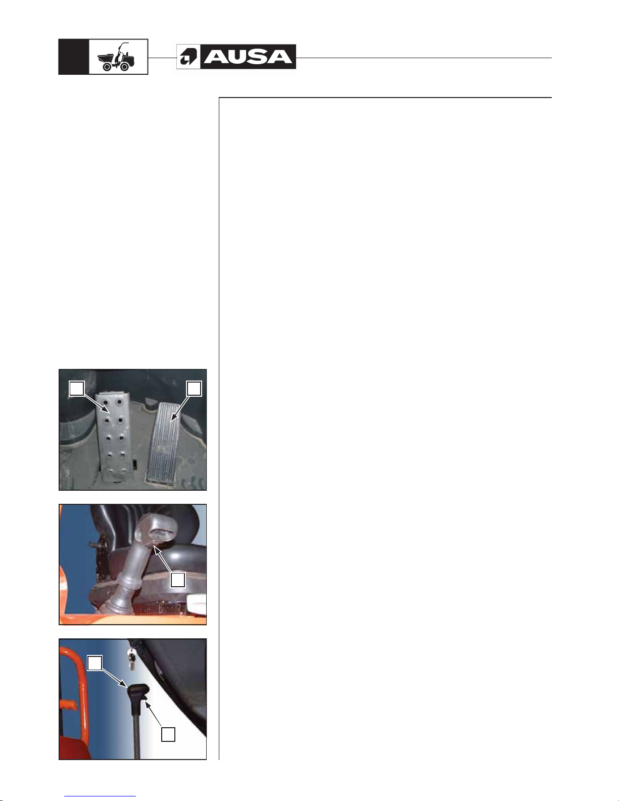
Pedals (fig.. 1)
a- Service brake pedal
b- Accelerator pedal
Acoustic warning for reverse gear
This sounds when the machine moves in reverse gear.
Joystick (fig. 2)
The joystick, located to the driver’s right, controls the direction of the dumper movement
and the operation of the cargo box.
Direction control (fig. 3)
The direction control is carried out by using the electric switch (c) located on the bottom
of the joystick handle. When the direction arrows are not lit, the direction control is in the
stop (neutral) position. By pushing the front of the switch the machine will move forwards
and by pushing the back of the switch, the machine will move backwards.
In each case the corresponding directional arrow will light up, green (forward) and red
(reverse).
WARNING!!
Do no make brusque changes in direction, in order to avoid any breakage to the gearbox.
Changing gears (fig. 3)
The vehicle has four gears which are selected using the gear stick (d).
The positions of the gear stick (d), with which to engage the different gears, are
described on the plate located on the engine protector, to the right of the driver.
On the handle of the gear stick there is an electric button (e) which disconnects the
transmission, this should be held down in order to change gear.
WARNING!!
Do not activate the gear stick without pressing the electric button (e), in order to avoid
any possible breakage to the gearbox.
(fi g. 1)(fi g. 3) (fi g. 2)
a
a
a
d
a
c
a
e
a
b
Page 21
D 900 AP / D 1000 AP / D 1000 APG
19
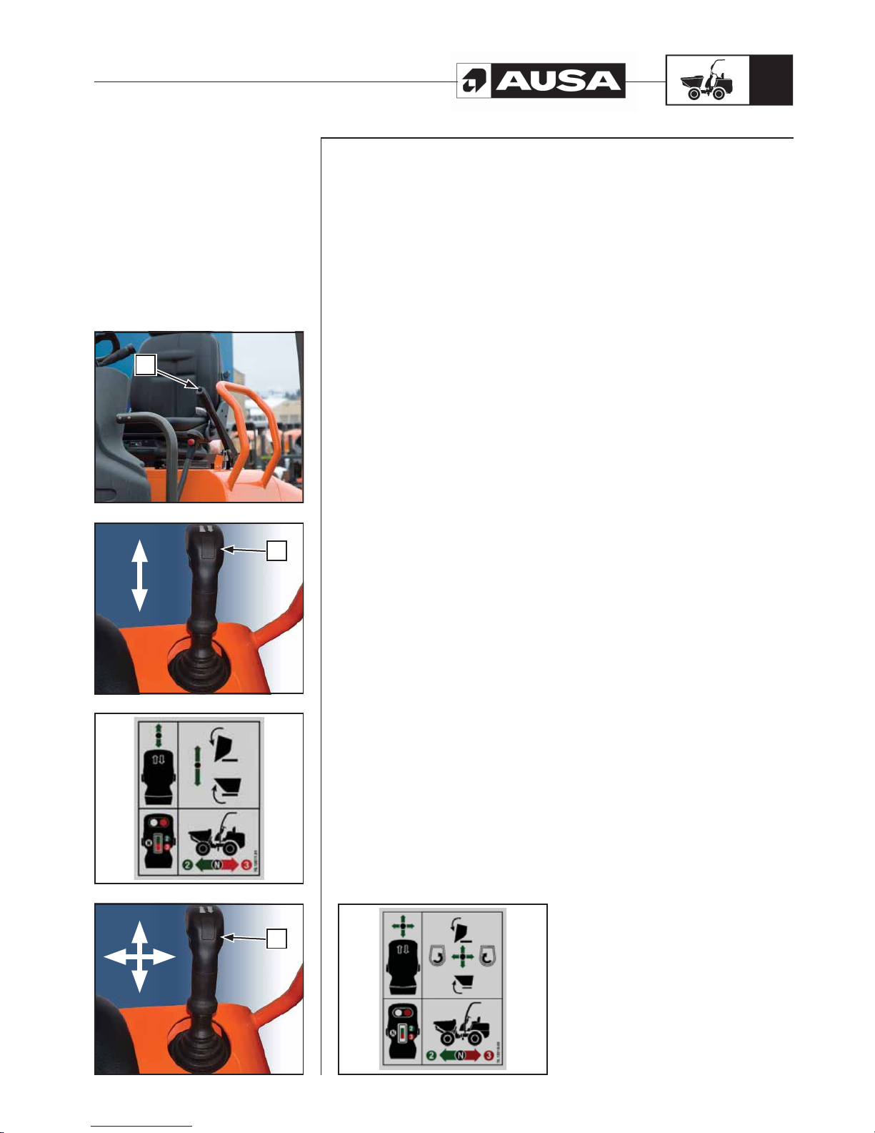
Parking brake (fig. 1)
The parking brake is activated using the lever (a) and cable with limit located on the left
side of the operator’s seat.
Pull up the lever until blocking the wheels.
To release the handbrake pull down the lever by pushing the button fitted at the front side
of the lever and fit it at rest position.
NOTE: The dumper has a device which disconnects the transmission when the parking
brake is activated.
Emergency Brake
In the event of emergency use the parking brake.
Skip's controls (fig. 2, 3, 4, 5)
D 900 AP and D1000 AP models (fig. 2, 3). Skip operations are done with the
joystick. By pushing lever (b) to the front, the skip tips forward and by pulling (b) back
the skip tips backwards up to its rest position.
D 1000 APG models (fig.4, 5). By pushing lever (b) to the front tips the skip forward
and by pulling it back the skip tips backwards up to its rest position.
The skip rotates to the left or right depending on moving the joystick to the left or to the
right.
Before rotating the skip, it must be raised enough to clear the locking device. When the
skip is fully lowered, you should locate it into the “V”.
Controls
instruments
equipment
(fi g. 4)
(fi g. 5)
(fi g. 3) (fi g. 2) (fi g. 1)
a
a
a
b
a
c
Page 22
D 900 AP / D 1000 AP / D 1000 APG
20
(fi g. 3) (fi g. 2)(fi g. 4) (fi g. 1)
Controls
instruments
equipment
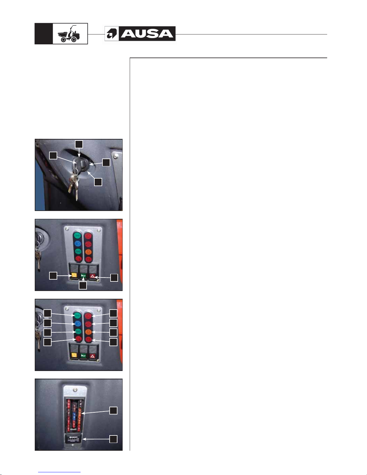
Control panel and controls
These are situated on the front operator protector and on the joystick.
1- Engine contact, preheating and stop switch (fig. 1)
This is located on the right side of the front protector.
a- Stopping
b- Preheating
c- Start-up
Switches (fig. 2).
D- Rotating beacons
E- Horn.
F- Warning (only on light version dumpers)
These are located on the right side of the front protector . To turn on, press the button
and it will light up. To turn off, press the button again.
Indicators.
These are also situated on the right side of the front protector (fig. 3).
G- Position lights lamp (only with lights option). This lamp is lit when this type
of lights are selected.
H- High beam lights lamp (only with lights option). This lamp is lit when this
type of lights are selected.
I- Indicator lamp (only with lights option). This lamp blinks to signal a change
in direction with the indicators.
J- Engine temperature lamp. If lit, this means that the engine temperature is too
high. Stop immediately in order to determine the cause of the problem. This could
be due to low level of coolant, dirt in the radiator , thermostat malfunction or a broken
alternator belt or water pump.
K- Air filter lamp. Indicates when the air filter is dirty or obstructed
The filter element must be cleaned or changed immediately.
L- Engine oil pressure lamp. When the contact is activated it will light and will turn
off when the engine is in operation. If the engine is functioning and the warning light
is lit, the engine must be stopped immediately to prevent any damage. Check the
oil level and add if necessary.
M- Preheating lamp. When this lamp is lit it indicates that the engine glow plugs are
in operations and are heating the combustion chamber to a temperature which will
enable the firing of the vaporised diesel fuel.
N- Battery charge lamp. With the contact activated, it will light when the alternator is
not charging the battery and it will go out when the engine starts to run. If it remains
lit, stop the engine and determine the cause.
O- Fuse box (fig. 4).
Located on the left side of the front protector (O). The fuse box contains 11 fuses.
See the Electrical Circuit in this Manual to identify the number and function of each
fuse.
P- Hourmeter (fig. 4)
This is located underneath the fuse box (P). The hourmeter records the time that
the engine is in operation, in hours. This allows the dumper maintenance to take
place at the appropriate periods.
See the LUBRICATION AND MAINTENANCE CHART section in this Manual.
1
a
b
c
D
F
E
J N
I M
H L
P
G K
O
Page 23
D 900 AP / D 1000 AP / D 1000 APG
21
(fi g. 1)(fi g. 2)
Controls
instruments
equipment
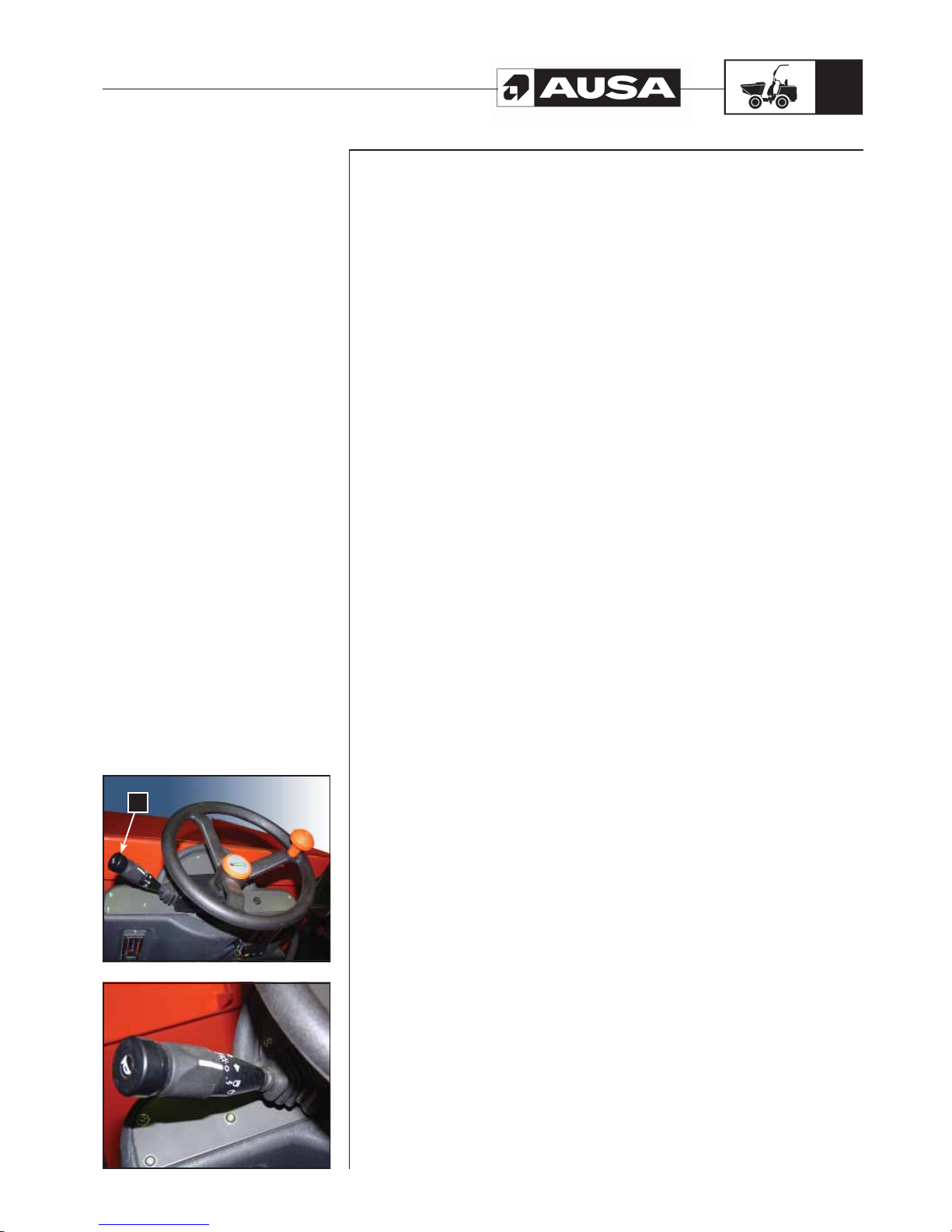
Multifunction switch (fig. 1, 2)
Located on the steering column.
Direction indicators. Moving the lever (a) from its neutral position towards the driver,
the left direction indicator is selected and pushing the lever forwards, the right direction
indicator is selected. When the direction indicators are selected, the lamp (l) (see fig.3
of the previous page) blinks on the control panel.
Position / low beam / road lights and dazzle lights. By turning the lever (a) to the first
position the position lights are turned on. By turning it to the second position the low
beam lights are turned on. By pushing the lever down the high beam is turned on. Pulling
the lever upwards selects the dazzle lights.
Horn. Activated by pressing the end of the multifunction switch.
Use of accessories and equipment
In the case of the vehicle being equipped with accessories, before using them, carefully
read the specific instructions manual for the accessory provided by its manufacturer and
supplied together with the main dumper manual.
In the case of accessories and equipment being assembled on the basic chassis of
the dumper by companies not connected to the manufacturer, all prescriptions and
limitations of the dumper in relation to mass and dimensions, efficiency of the lighting
system and adjustments thereto, along with the need for protection for additional
systems must be taken into account in order to guarantee the safety of the dumper.
a
Page 24
D 900 AP / D 1000 AP / D 1000 APG
22
Entering and exiting the operator’s cab.
Do not grab and pull the steering wheel in order to enter the operator’s cab, hold the
handles provided for this purpose and always support your foot on the step in order to
avoid slipping both when entering and exiting the cab.
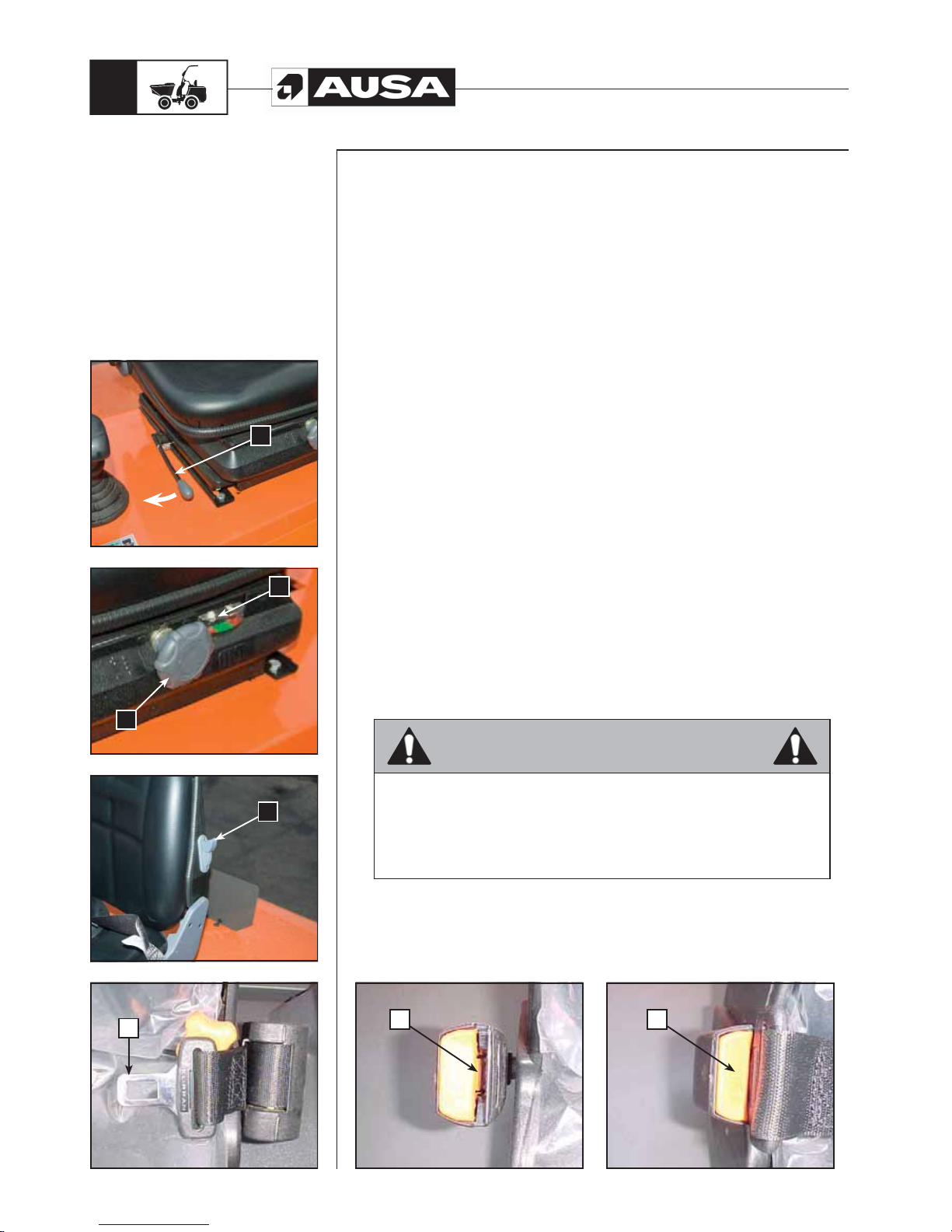
Seat adjustment (fig. 1, 2, 3)
Each day, before operating the dumper, adjust your seat to a position in which you feel
comfortable.
Pull the lever (a) to the right to unlock the seat. Slide the seat forward or backwards to
reach the desired position.
Releasing the leaver the seat locks.
The damping of the seat can be adjusted between 50 and 130 Kg, depending upon
the operator’s weight; to do so turn knob (b) clockwise or counter-clockwise in order to
adjust properly the seat damping.
For correct adjustment of the damping, with the operator sitting the needle (c) should
remain within the range of green scale into the gauge.
Using the lever (d) located on the left side of the seat backrest, the backrest inclination
can be changed. Pulling down the lever the backrest unlocks. Adjust the backrest and
release the leaver to lock again.
Ensure that you fasten your seatbelt.
Seatbelt (fig. 4, 5, 6)
To fasten the seatbelt, insert the snap (e) into the fastener (f) until your hear the locking
“click”.
To unfasten the seatbelts, press button (g).
The seat belt adapts the body of the passenger using it, giving them freedom of
movement but adjusting the belt to the physical constitution of the driver.
If the machine is parked on a steep slope, the reel could become locked; this is normal.
Additionally the reel curling device blocks the strap every time the strap is suddenly
pulled or in case of sharp braking, collisions or turning operations at high speed.
Checks
With the engine on and the dumper stopped, carry out the checks and tests indicated in
the PRE-OPERATION CHECK section of this manual.
WARNING
Before each period of use of the dumper, check the correct operation of
the steering, brakes, hydraulic controls, instruments, safety equipment and
direction control.
A machine which functions correctly is more efficient and could prevent
accidents.
Carry out all necessary adjustments or repairs before operating the dumper.
(fi g. 4)
(fi g. 5)
(fi g. 6)
(fi g. 3) (fi g. 2) (fi g. 1)
Operating
the dumper
a
c
b
d
e
f
g
Page 25
D 900 AP / D 1000 AP / D 1000 APG
23
Operating
the dumper
Loading the dumper
When the dumper is loaded, respect the maximum allowed load.
See the SPECIFICATIONS section in this manual
Load capacity (see dumper identification plate)
The nominal load is the load which the dumper can safely transport, it is determined by
the weight of the load.
The use of attachments may reduce the load capacity.
The condition of the ground and the load method may affect safety conditions.
An overload on the cargo box makes the dumper unstable, hard to handle and may
cause the tipping over of the vehicle or breakage of some components.
WARNING:
Handling, stability and braking distance are affected when the dumper is loaded.
Correct loading and weight distribution are important. Never, overload, tow or pull a
load improperly. Always ensure that the load is supported and adequately distributed
before operating the dumper. Drive at slow speed and in accordance with the ground
conditions when transporting a load or towing a trailer.
Remember that a greater braking distance is required. Always place the load as low
as possible in order to reduce the effects of a high centre of gravity. Failure to follow
these recommendations could cause changes to the handling of the dumper with the
possibility of an accident occurring, which could cause serious injury or even death to
the operator.
The relation between the dumper and the load is conditioned by changes in:
- The use of attachments.
- Changes in the dumper movement and type of terrain in which the vehicle moves
- Smoothness and stability must be maintained whilst these factors constantly
vary during dumper operations.
This requires a careful judgement on the part of the operator.
Start up and stop
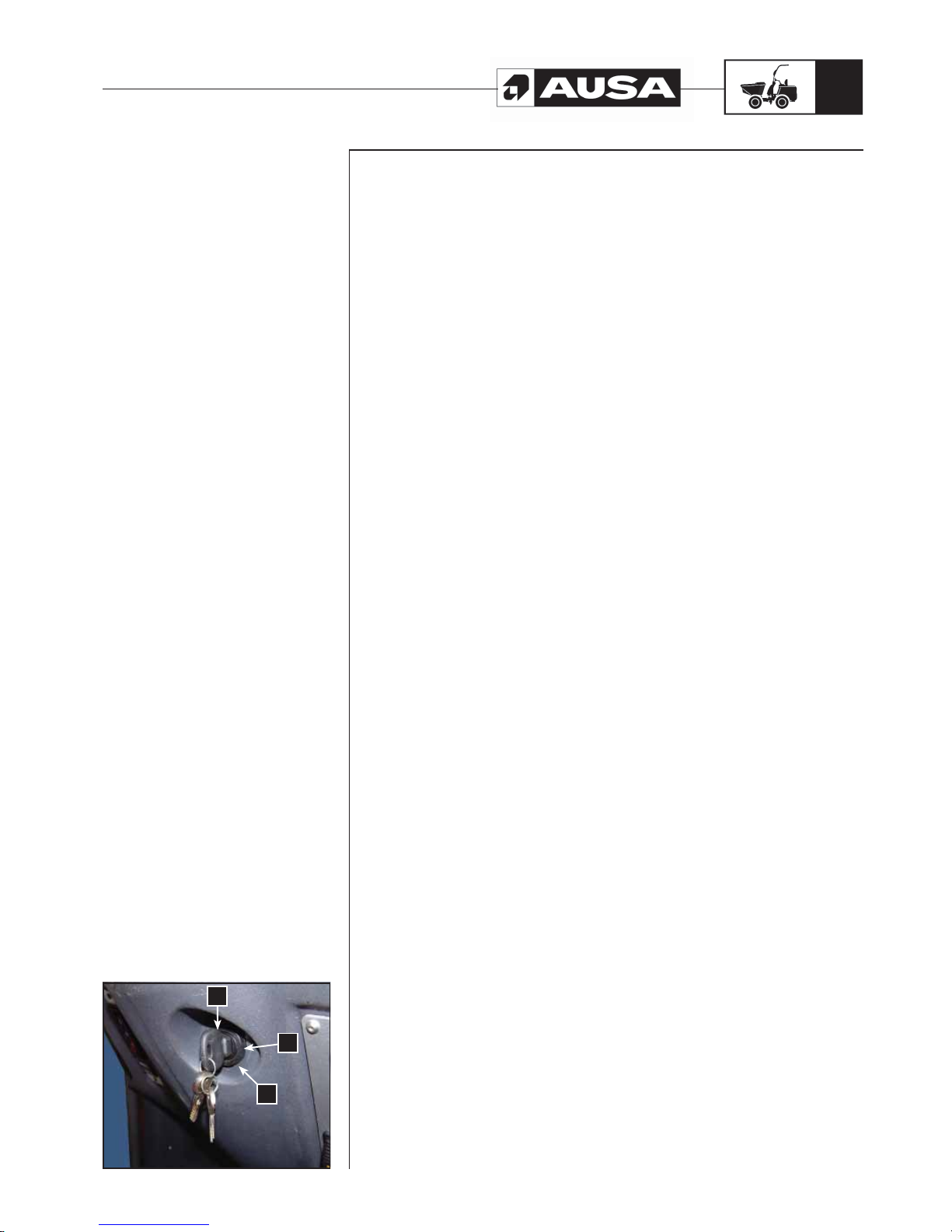
Start up (fig. 1)
For safety reasons when starting the dumper, the operator must be seated and with the
seatbelt fastened, the hand brake must be activated and a check that the gear stick and
the direction control switch are in the neutral position must be carried out.
Insert the key into the ignition switch and turn it to position (b) until the preheat lamp
turns off, press the throttle pedal a 1/4 of the way and turn the key to position (c) until
the engine starts. Do not maintain this position for more than 15 seconds. If the engine
does not start repeat the previous operations. Wait for 30 seconds between each try.
NOTE: This dumper has a starter lock.
Take into account that the electric switch for the direction control must be in the neutral
position.
IMPORTANT!
In cold temperatures, slowly increase the engine revolutions to achieve good lubrication
of the engine.
(fi g. 1)
a
b
c
Page 26

D 900 AP / D 1000 AP / D 1000 APG
24
Operating
the dumper
Emergency start
If the engine cannot start due to a flat battery, another 12V booster battery can be used
together with the corresponding jump leads to connect the two batteries. If you use the
battery of another machine or dumper, avoid the two machines touching.
1- Apply the dumper’s parking brake.
2- Open the dumper engine cover.
3- Connect the (+) positive terminal of the battery with the (+) terminal of the
dumper and with the other cable connect the (-) negative terminal with the (-) of
the dumper.
4- Start the dumper in the normal way.
5- Disconnect the cables from the terminals, first the (+) positive terminals and then
the (-) negative terminals.
Parking the dumper and stopping the engine.
Whenever the dumper is parked, either at the end of the day or in order to carry out any
maintenance work, it should be parked on level ground. Apply the dumper’s parking
brake. Keep the engine in idle for 1 minute, if the dumper has been working at full load.
Then turn the ignition key in and anti-clockwise direction to stop the engine. Connect the
gear stick in such a way that it creates additional holding for the machine in case of the
parking brake failing. Chocking the wheels with suitable blocks is also recommended.
Remove the key from the ignition and take it with you. Never leave the key in the parked
dumper.
Page 27
D 900 AP / D 1000 AP / D 1000 APG
25
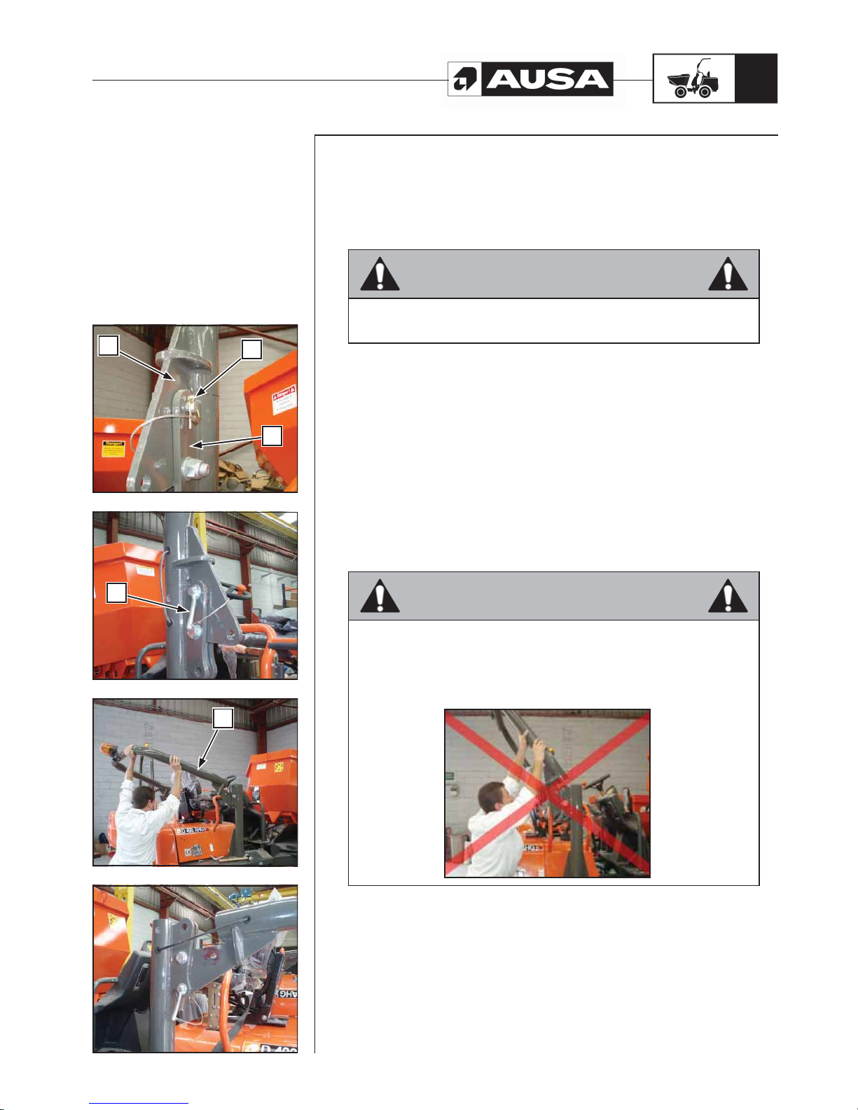
Procedure for folding the ROPS protector arch (fig. 1, 2, 3, 4)
The ROPS folding protector arch is comprised of two sections (h) and (i) can pivot to
approximately half of its length allowing it to be folded towards the rear of the machine
and thereby reducing the total height of the machine for transport purposes.
Transport position
WARNING
Do not work with the machine if the ROPS protector arch is in the Transport
position.
To place the ROPS protector arch in this position follow the instructions below:
1- Remove the two locks (j) from the bolts (k) located on each side of the ROPS
protector arch.
2- Remove the bolts (k).
3- Carefully fold the top part of the ROPS protector arch (h) backwards to the
Transport position.
4- Once it is correctly positioned (fig. 4), replace the bolts (k) and then the locks
(j).
Working position
To place the ROPS protector arch in this position follow the instructions in the reverse
order.
WARNING
Carefully ensure you position your feet on the machine or on the floor in a
stable position to ensure that you do not lose your balance whilst folding back
the ROPS protector arch. Similarly, take care to not place you hands around
the protector arch fold area (as shown in fig.5) as this could cause serious
injury.
(fi g. 5)
(fi g. 4) (fi g. 3) (fi g. 2) (fi g. 1)
Operating
the dumper
a
h
a
k
a
j
a
i
a
h
Page 28

D 900 AP / D 1000 AP / D 1000 APG
26
Break in period
Engine
The engine in this dumper requires a break in period of 50 hours before operating the
vehicle at full load.
CAUTION:
This dumper has a 4-stroke engine. Oil must be added to the engine base only.
During this period, maximum throttle should not exceed 3/4 of the pedal movement.
However, brief full acceleration and speed variations contribute to a good break in.
Continued wide open throttle accelerations, prolonged cruising speeds and engine
overheating are detrimental during the break in period.
First inspection (50 hours)
As with any precision part of a mechanical element, we suggest that after the first 50
hours or 30 days from purchase, whichever is reached first, the dumper is inspected by
an authorised AUSA dealer. This inspection will give you the opportunity to discuss the
unanswered questions you may have encountered during the first hours of operations.
Page 29
D 900 AP / D 1000 AP / D 1000 APG
27
Before starting
the dumper
WARNING
The pre-operation check is very important prior to operating the vehicle.
Always check the proper operation of critical controls, safety systems and
mechanical components before starting. If the pre-check operations are not
done as specified here, severe injury or even death might occur.
- Check tyre pressure and condition.
- Familiarise yourself with the controls and ensure that they function correctly.
- Verify that the steering operates freely.
- Activate the throttle pedal various times to ensure it operates freely. It must return
to the original position when released.
- Activate the brake pedal to ensure that the brakes function correctly. The pedal
must return to the original position when released.
- Ensure that the gear stick functions correctly.
- Check fuel, engine oil, hydraulic oil, coolant and brake fluid levels.
- Check for oil leaks on the engine, in the transmission components or in the
hydraulic circuit.
- Clean the lights and the lamps (if there are any).
- Ensure that the engine protector is correctly covered.
- Ensure that the seatbelts are correctly secured.
Before starting the day, carefully inspect this devices with special attention to:
- Cuts or threading on the belt
- Wear or damage to anchor points
- Poor functioning of the seat belt buckle or the retracting roller
- Loose threads or poor stitching
- If transporting cargo, respect the load capacity. Ensure that the cargo is properly
distributed.
- Review the engine parts while it is off. Check fixings.
- Check that the ignition switch, the headlights, the direction indicators, taillights
and acoustic warning and lights for reverse are functioning correctly.
- Start the engine and drive forward slowly a short distance and press the brake
pedal to check the brakes.
Correct any problem you may have found before operating the vehicle.
Consult an authorised AUSA dealer if necessary.
Page 30
D 900 AP / D 1000 AP / D 1000 APG
28
(fi g. 2) (fi g. 1)
Transporting
the dumper
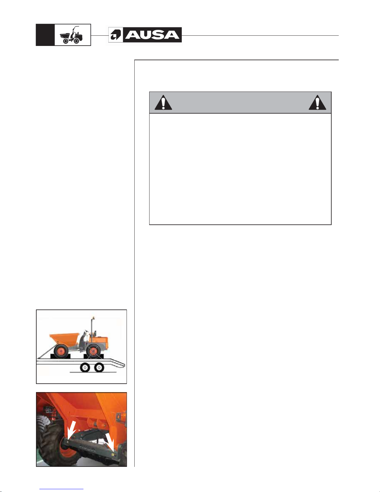
Securing/immobilising the dumper on the truck bed (fig. 1, 2)
When transporting the dumper on a truck bed or low loader, carefully follow the advice
given in the following chart:
WARNING
Before raising the dumper onto a trailer or truck bed, make certain that the
ramp is strong enough to support the weight of the dumper and that the truck
bed surface is free from debris, oil, grease or ice.
• Do not transport the dumper with the fuel tank full.
• Make certain your seatbelt is properly fastened.
• Move the dumper slowly and carefully up or down the loading ramps.
• Apply the dumper’s parking brake.
• Connect the gear stick in such a way that it creates additional retention for
the dumper in case of the parking brake failing.
• Stop the engine and remove the key from the ignition.
• Apply chocks to the front and rear wheels.
• Firmly secure the dumper to the truck bed or low loader with chains, cables
or slings at the points provided to prevent any movement.
- FRONT AXLE: with the chassis eyelets (fig. 2)
- REAR AXLE: above the rear wheels.
• Take into account that the securing systems should be
adequate and sufficiently resistant for this purpose.
Page 31
D 900 AP / D 1000 AP / D 1000 APG
29
(fi g. 4) (fi g. 3) (fi g. 2) (fi g. 1)
Transporting
the dumper
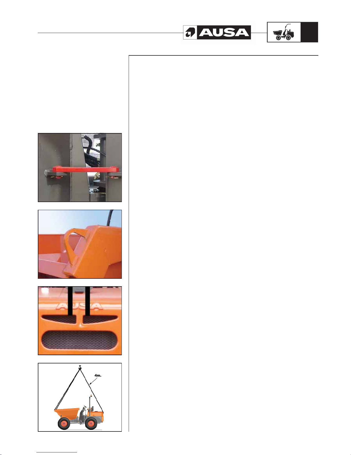
Loading the dumper with a crane (fig. 1, 2, 3, 4)
When the dumper is loaded onto a truck using a crane and a cable or sling:
• Before moving, immobilise both parts of the sling using the linking bar provided for
this purpose.(fig. 1)
• Hook the cable or sling on the points provided for this purpose on the machine.
- FRONT PART: by the lugs welded on the front of the cargo box (fig. 2)
- REAR PART: by the counterweight (fig. 3)
• Always carry out this operation with the machine unloaded.
• Before hoisting check that the cable or sling is firmly hooked and that both the
crane and the cable or sling have sufficient capacity to lift the load.
• During hoisting do not allow any person to be on the truck or any spectators within
a 5m radius.
• Always undertake this operation on flat and horizontal ground.
• Use guide ropes or other systems to avoid the machine pivoting or turning.
Also take into account the following recommendations.
• The slings must be long enough to form an angle wider than 45° with the horizontal.
• Always elevate the machine in the most horizontal position possible.
Page 32
D 900 AP / D 1000 AP / D 1000 APG
30
Transporting
the dumper
(fi g. 1)
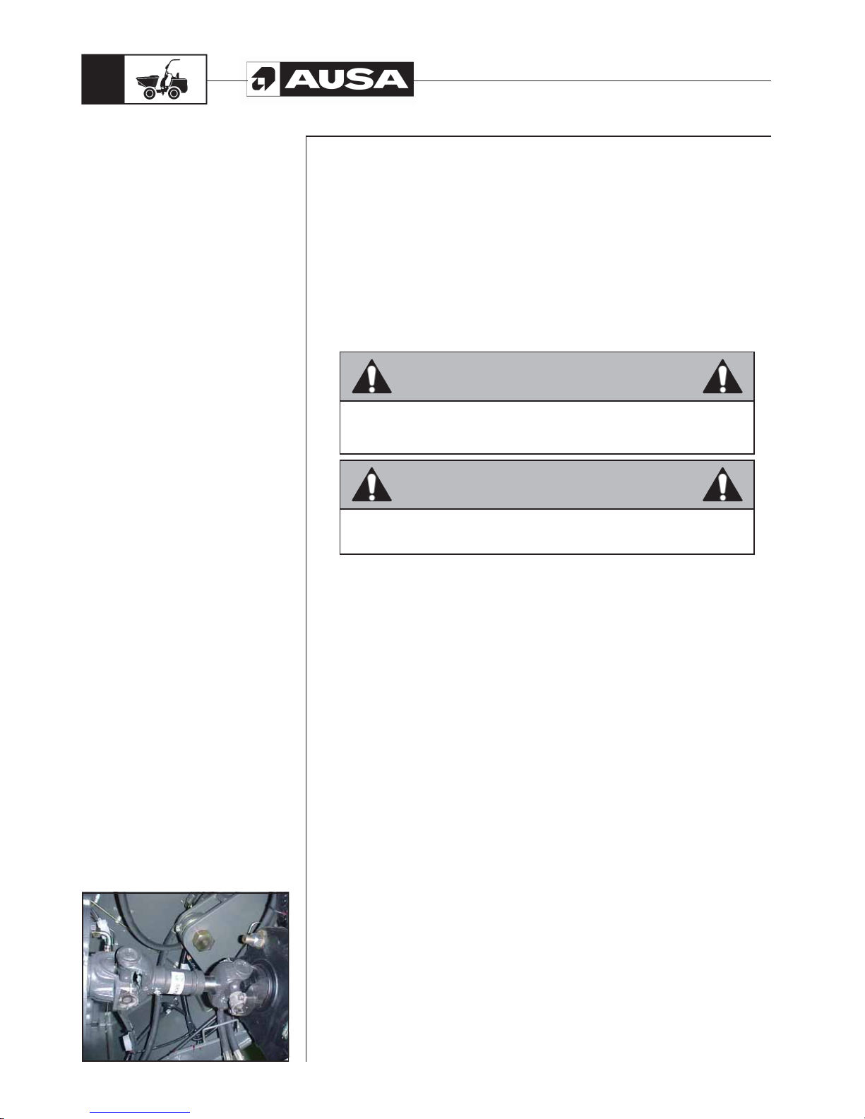
Towing the dumper (fig. 1)
Towing dumpers is only recommended in cases of breakdown when there is no
alternative. Whenever possible, we recommend repairing the vehicle without moving it.
Otherwise, the towing must only be done slowly and over short distances.
In order to avoid cavitation and possible transmission seizure during towing, it is
imperative that the transmission universal drive shaft goes into the gearbox and the
gearbox is disconnected. Failure to take this precaution may cause severe damage to
the transmission.
Remove the parking brake.
Drive slowly and carefully without exceeding 10 km/h (6 Mph), complying with the
country regulations relating to the towing of an off-road vehicle on roads and highways.
The dumper must be towed using a solid towbar to avoid any sideways oscillation, and
always with the chassis fixed rigid with the joint beam included (See fig.1 previous page).
WARNING
If you tow the dumper, you must disconnect the upper transmission universal
drive shaft (fig. 1) in order to avoid oil cavitation, which may cause severe
damage to the gearbox.
WARNING
Do not tow this dumper behind a car or other vehicle.
Page 33
D 900 AP / D 1000 AP / D 1000 APG
31
Liquids and
lubricants
This section specifies the recommended liquid and lubricants. See the
“MAINTENANCE CHART” on this Manual for the recommended change /
service intervals.
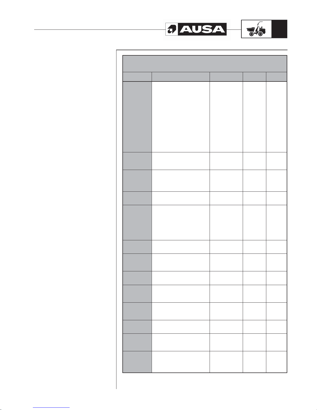
FLUID OR
LUBRICANT
SPECIFICATION REMARKS AUSA P/N
CAPACITY
(UK Gal.)
FUEL
Use clean auto diesel (class A),
preferably in accordance with Direc-
tive 98/70/EEC modified by direc-
tive 2003/17 or Standard EN 590
equivalent to the same. In Spain this
corresponds to RD 1728/1999. For
the USA market, it should conform
to Grades 1D and 2D of ASTM D975
and for supplies not conforming
to these requirements, in no event
should the sulphur content exceed
0.5% by mass. Initially, the use of
REM type biodiesel or similar is not
recommended. In the event that
it is used, it should not be used in
proportions higher than 5 % of the
fuel mixture
15.4
KUBOTA
ENGINE OIL
Engine oil in accordance with MIL-
2104C / API CD or higher
See
KUBOTA
ENGINE OIL
in this section
461.00099.00 2.9
ENGINE
COOLANT
Ethylene glycol antifreeze with corrosion inhibitors for aluminum engines
with internal combustion. 40% glycol
/ 60% distilled water in Standard
machine.
See
COOLANT
in this section
45.00075.00 1.1
HYDRAULIC
CIRCUIT
Hydraulic oil ISO Grade SAE 20 in
accordance with ISO 6743/4 HM DIN
51524
461.00001.00 14.3
TORQUE
CONVERTER
AND POWER
SHUTTLE
10W or 10W 30 Grade mineral oils or
automatic transmission fluids which
meet at least one of the following
SPECIFICATIONS are allow-
able for use in ambient temperatures
of between -20 and 40 Deg.C: SAE
10W or 10W30 A.P.I. GL4, Allison C3,
MIL-L-2105B, or Caterpillar TO2.
See
GEARBOX AND
CONVERTER OIL
in this section.
461.00015.00 2.6
FRONT AXLE
DIFFERENTIAL
OIL
Transmission oil SAE 90 in accor-
dance with
API GL5 LS / MIL-L-2105D
See
FRONT AXLE OIL
in this section.
461.00099.09 8’5 Liters
FRONT AXLE
HUB
REDUCTION
OIL
Transmission oil SAE 90 in accor-
dance with
API GL5 LS / MIL-L-2105D
See
FRONT AXLE OIL
in this section.
461.00099.09
0’8 Liters /
wheel
REAR AXLE
DIFFERENTIAL
OIL
Transmission oil SAE 90 in accor-
dance with
API GL5 / MIL-L-2105D
461.00004.01 8’5 Liters
REAR AXLE
HUB
REDUCTION
OIL
Transmission oil SAE 90 in accor-
dance with
API GL5 / MIL-L-2105D
461.00004.01
0’8 Liters /
wheel
TRANSFER
BOX
Transmission oil SAE 90 in
accordance with API GL5 / MIL L-
2105B
See
TRANSFER BOX
OIL
in this section.
461.00004.01 0.32
BRAKE FLUID
LHM brake fluid (green) mineral
based in accordance with ISO VG32.
See
BRAKE FLUID
in this section
461.00001.01 0.21
BATTERY
ELECTROLYTE
Distilled Water
See section
BATTERY
ELECTROLYTE
in this section
GREASING
POINTS
Calcic grease NLGI-3 consistency
See section
GREASING
POINTS
in this Operator’s
Manual
461.00009.00
Page 34
D 900 AP / D 1000 AP / D 1000 APG
32
Liquids and
lubricants
(fi g. 1)
Fuel
Use automotive clean diesel (class A), which preferably meets 98/70/CEE standard
amended by standard 2003/17 or the equivalent EN 590 standard.
In Spain RD 1728/1999 applies.
For the USA market, it must meet Grades 1D and 2D of the ASTM D975 standard, in
supplies which do not meet these standards, the sulphur content should never exceed
0.5% mass. In principal, the use of REM type biodiesel or similar is not recommended.
In case of use, the proportion used should not exceed 5% of the fuel mix.
KUBOTA engine oil
Use oil for four stroke engines which meets requirements MIL -L-2104C / API CD or above.
Always check the API quality on the oil container label to ensure that it is the required
quality.
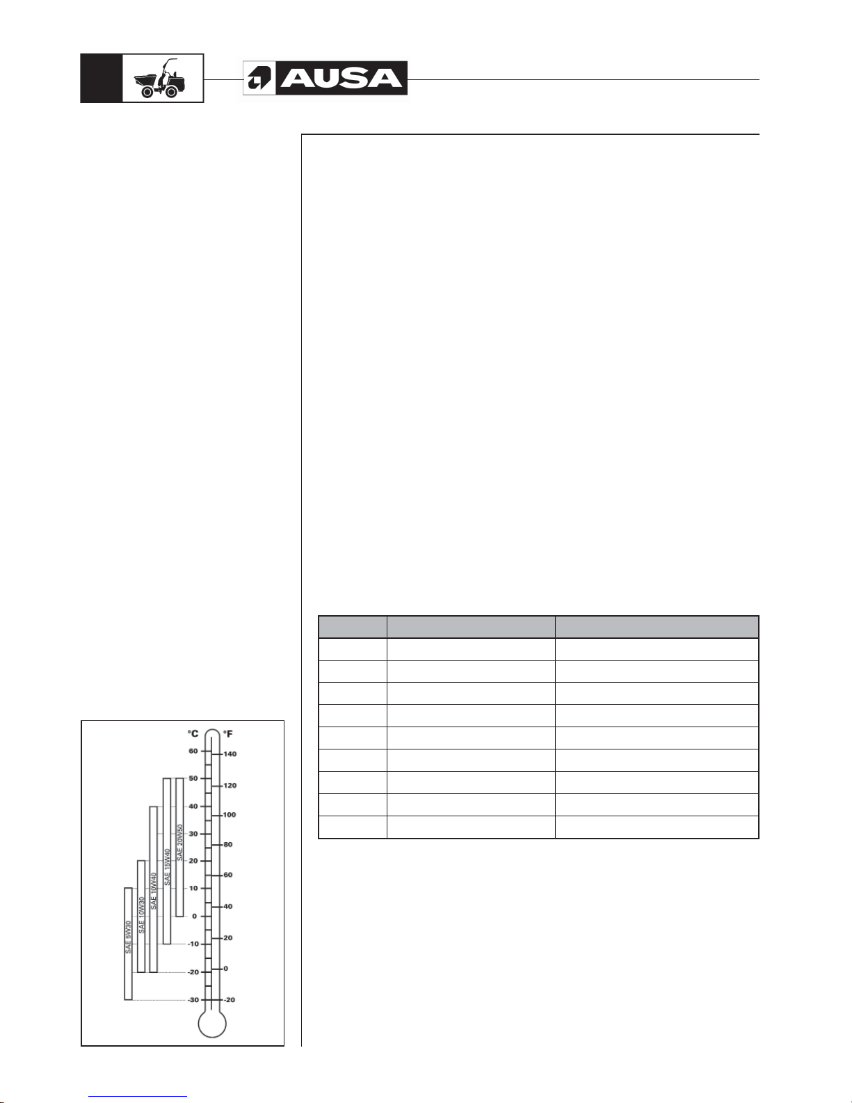
Y our dumper leaves the factory with SAE 15W40 oil viscosity . However, depending on the
climate, consult the chart to select the most appropriate viscosity (fig. 1).
If oils of different brand names are used, ensure that you completely empty the crankcase
before adding the new oil.
AUSA recommends REPSOL AUSA EFFICIENT for Diesel engines p/n 461.00099.00
Coolant
Always use ethylene-glycol antifreeze containing corrosion inhibitors especially for
internal combustion aluminium engines. The cooling systems must be filled with distilled
water and antifreeze solution (60% water, 40% antifreeze in a standard machine for
temperatures ranging from -17 ºC to 127 ºC) (50% water , 50% antifreeze for temperatures
ranging from -35 ºC to 145 ºC)
Gearbox and converter oil
Mineral oil or transmission oil SAE 10W or 10W30 as per API GL4 / MIL -L-2105B, ALLISON
C3 or CATERPILLAR TO2 for ambient temperatures from -20 to 40ºC.
The following list can be used as reference:
Brand A.T.F. Liquid Mineral Oils
Mobil
Delvac 1310 or Mobilube HD 80
Shell
Donax TM or TA Donax TC 10W.
B.P. Autran MBX. Vanellus C3 10W
Esso Torque Fluid 56 Unifarm.
Castrol
Castrol RX 10 or Multiplant
Texaco Texamatic C3 , 9230 or 9226
Total Total Fluid ATX.
Elf Elfmatic G3 or Elfmatic H
Fina Finamatic HD Kappa TD 10W
Page 35

D 900 AP / D 1000 AP / D 1000 APG
33
Liquids and
lubricants
Reduction a wheel Front axle oil
SAE 90 Oil as per API GL5 LS / MIL-L-2105D SPECIFICATIONS
Oil AUSA COMPEN EFFICIENT p/n 461.00099.09 with the following characteristics:
Friction coefficient modifying additives
“Extreme pressure” and anti-wear capacity
Good antirust and anticorrosion characteristics
Excellent thermal stability
Avoids vibrations and noises
The following oils can also be used:
- BP TERRAC SUPER TRANSMISSION S o BP TRACTAN 8.
- ESSO Torque Fluid Type 56 o 62.
- AGRICASTROL AS Special.
- GULF Universal Tractor Fluid.
Transfer box oil
The oil recommended by the manufacturer is:
MOBILUBE HD 90
CASTROL DEUSON EP 90
SHELL SPIRAX 90 EP
BP HYPO GEAR 90
Brake fluid
Brake fluid type LHM (green) with mineral base as per ISO VG32.
CAUTION:
To avoid serious damage to the brake system, do not use fluids other than the
recommended one, or mix different fluids for topping up. Under no circumstances
should vegetable oil based brake fluid be used (SAE J1703).
Battery electrolyte
This dumper is equipped with a battery that requires maintenance. Add distilled water
if necessary.
Page 36
D 900 AP / D 1000 AP / D 1000 APG
34
Special procedures
1.- Engine Overheat
If the engine overheats and the temperature indicator on the instrument panel is lit, try
the following:
Check and clean the radiator fins. See the “PERIODIC MAINTENANCE OPERATIONS”
section of this manual.
WARNING
The radiator can get very hot, wear gloves before touching the radiator.
Reduce the dumper speed but try to keep the vehicle moving to supply air to
the radiator.
If the engine is still overheating after approximately 1 minute, stop the dumper
and place the gear stick or the direction control switch in the neutral position,
apply the parking brake and stop the engine.
Allow the engine to cool. Check the coolant level and refill if necessary.
If the engine continues to overheat, see an authorised AUSA dealer as soon
as possible.
2.- Post-operation care
When the dumper is used in salt water areas (beach areas, etc.), rinse with clean water
to preserve the dumper and its components.
Lubrication of metallic parts is highly recommended.
This must be performed at the end of each operation day.
When the dumper is operated in muddy conditions, rinsing the dumper is recommended
to preserve the dumper and its components.
NOTE: Never use high pressure water to clean the dumper ONL Y USE L OW PRESSURE
WATER. High pressure water can cause electrical and mechanical damage.
3.- Overturning
In the event that the dumper overturns:
it is important that the driver avoids being trapped between the machine and the ground.
To prevent this we recommend:
- Try to remain within the operator cab.
- Grasp the steering wheel firmly.
- Push feet firmly against the floor plate of the cab.
- Try to keep as far away from the point of impact as possible.
When the dumper is overturned or stays tilted on one side, replace the vehicle in its
normal operating position (on all four wheels).
WARNING!!
DO NOT TRY TO START UP THE DUMPER without first speaking with an AUSA
dealer.
- Remove the glow lamps.
- Turn the ignition key to position C (see OPERATING THE DUMPER section).
Keep the key in this position until the oil has left the combustion chambers.
WARNING!!
The oil will leave the combustion chambers at a high pressure and could cause injury.
- Replace the glow lamps.
- Check the engine oil level and refill if necessary.
If the pressure lamp remains lit after starting the engine, immediately stop the engine to
avoid internal damage and consult an authorised AUSA dealer to determine the cause.
Page 37

D 900 AP / D 1000 AP / D 1000 APG
35
Special procedures
4.- Dumper immersion
Should the dumper becomes submerged, it will be necessary to take it to an authorised
AUSA dealer as soon as possible.
DO NOT START THE ENGINE! Immersion of the dumper can cause serious damage
if the correct re-start procedures are not followed before starting the engine.
WARNING
Ask an authorised AUSA Utility dealer to fully inspect the fuel system as stated in the
LUBRICATION AND MAINTENANCE CHART.
5.- Storage and pre-season preparation
When a dumper is not in use for more than one month, proper storage is necessary.
Equally, after being store for a long period of time, consult an authorised AUSA dealer
for the correct start up procedure. When using the dumper after storage, preparation is
required.
Page 38
D 900 AP / D 1000 AP / D 1000 APG
36
(fi g. 1)
Periodic
maintenance
operations
In maintenance operations only use original AUSA spare parts.
This is the only way to guarantee that your dumper will remain as technically
efficient as when it was purchased.
In this dumper as with any other, there are parts and system which are subject to
wear and misalignment, which may affect reliability and driver safety, the environment
and the area, for example exhaust fume emissions, etc.
In accordance with Work Group Directives, inspections of these systems must be carried
out periodically and the results recorded on the forms provided by the Work Authorities
of each country. (89/655/CEE and RD1215/97).
Unless work on the engine demands that it be running, perform all repairs and
maintenance on the dumper with the machine parked and unloaded, with the gear stick
in neutral and the wheels blocked to keep the dumper from moving during servicing.
Unless otherwise specified, do not start the engine during maintenance operations.
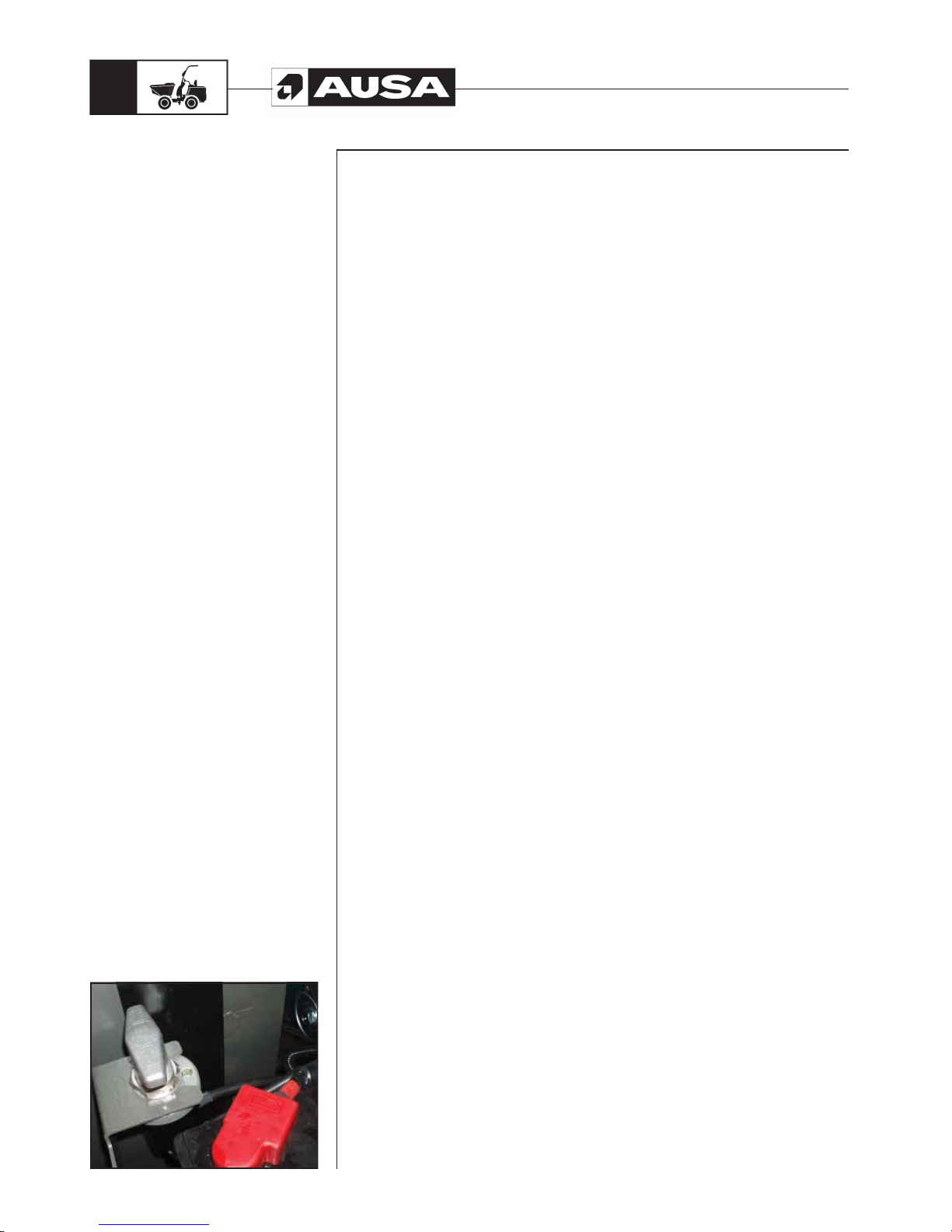
Disconnect the battery before carrying out any operation on the electrical system with
the disconnector (fig. 1). Never use a flame to check fluid levels.
Be environmentally friendly.
When changing oils or other fluids, use an appropriate container to collect the fluid and
ensure that you are not harming the environment during the operations and take all
replaced materials (batteries, coolant, tyres, etc.) to the appropriate recycling centres.
In cases of leaks of substances which could be harmful to people or the environment,
urgently take the necessary actions to reduce the impact, e.g. in oil leaks, plug the leak,
place a container underneath to collect the oil, spread absorbent material or dig up and
remove the contaminated ground if necessary.
Washing the dumper
During the washing process, care must be taken to avoid aiming the pressurised water
jet at the air intake (air filter), battery, instrument panel, alternator and other electrical
equipment since this can damage the components.
Roadside breakdown
In the case of a breakdown when driving on a road, you must use the warning triangles.
The triangles are offered as optional equipment.
Page 39
D 900 AP / D 1000 AP / D 1000 APG
37
(fi g. 3) (fi g. 2) (fi g. 1)(fi g. 4)
Periodic
maintenance
operations
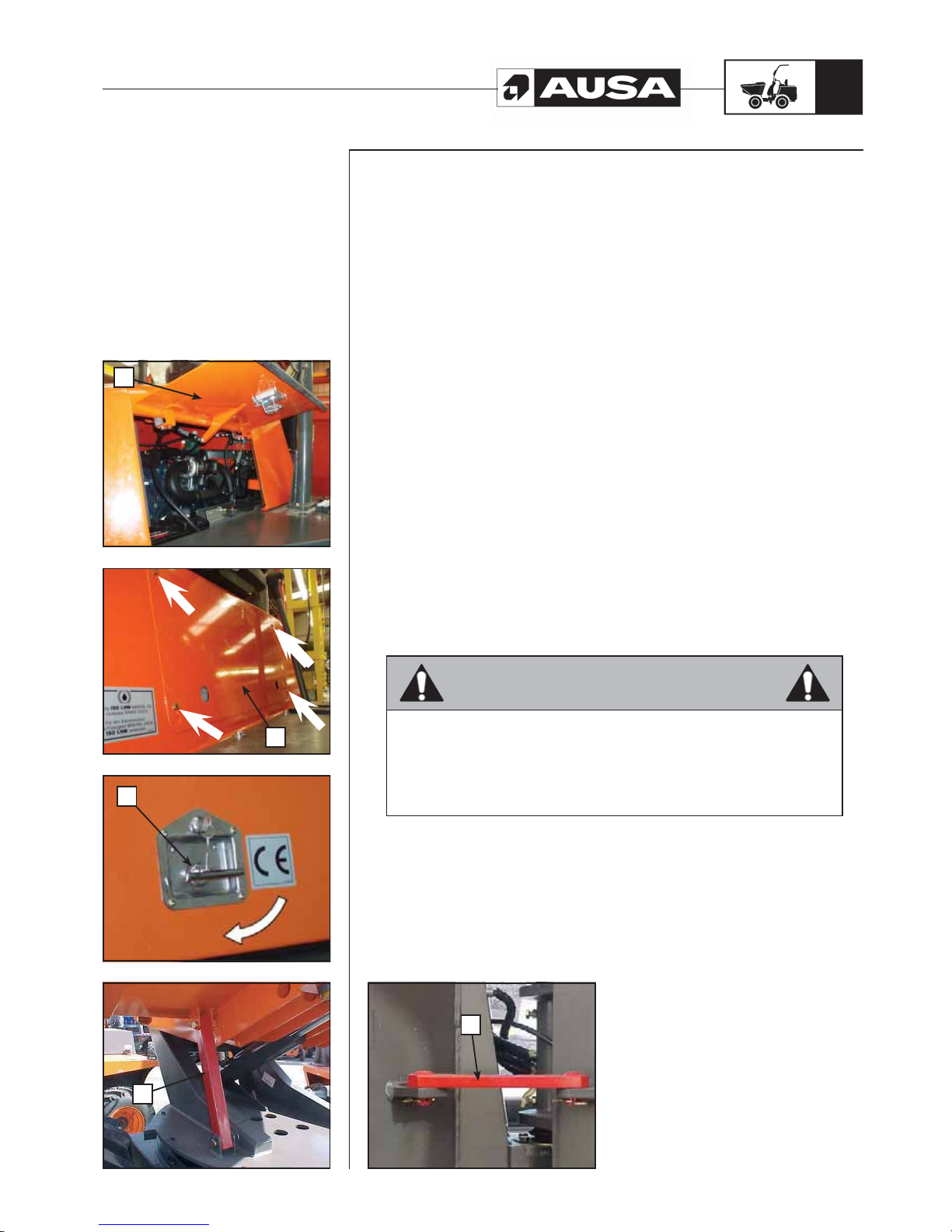
Access for maintenance (fig. 1, 2, 3)
The engine, the transmission and the filters are located under the side covers at the
rear of the machine (fig. 1) and underneath the maintenance access panel, located
to the side of the operator’s seat. (fig. 2). In order to access them you must follow this
process:
a. Engine cover
b. Maintenance access panel
c. Engine cover locks
To lift the side covers, lift the lock and turn it to the right (fig. 3). Lift the cover (right or
left) by pulling it. There are gas springs which compensate the weight and hold it in the
elevated position.
To access the maintenance access panel, unscrew the fixing screws and remove the
cover.
Lock to avoid the descent of the cargo box (fig. 4)
There is a prop to avoid the lifted bucket box from descending when maintenance
operations are being carried out.
d. Lifted bucket prop
This ensures that you work on the machine in complete safety.
Chassis articulation linking bar (fig. 5)
Before carrying out any intervention which requires you to be located between the two
parts of the chassis, immobilise the articulation with the linking bar provided for this
purpose.
e. Chassis articulation linking bar
WARNING
Should removal of a fixing device (lock tabs, self locking fasteners, etc) be
required to carry out disassembly / assembly, always replace with a new one.
Initial maintenance is very important and must not be neglected. See the
MAINTENANCE CHART in this Manual. The maintenance of some of the
components can be carried out by the clients if they wish to do so.
Other operations must be carried out by an authorised AUSA dealer.
(fi g. 5)
a
b
c
d
e
Page 40
D 900 AP / D 1000 AP / D 1000 APG
38
(fi g. 3) (fi g. 2) (fi g. 1)
Periodic
maintenance
operations
1.- Engine
For operation instructions, a list of spare parts and for general maintenance consult the
engine manual or the LUBRICATION AND MAINTENANCE CHART of this Manual.
Alternator belt
Periodically check the tension in the alternator belt. Also check for cracks or other
damage. Contact an AUSA dealer for replacement of the alternator belt.
2.- FUEL CIRCUIT
Current regulation in regard to exhaust emissions demands that the values of the exhaust
emission components are kept below the maximum limits authorised by the regulations
throughout the useful life of the machine. Consequently, the engine maintenance plan
must be carefully followed, with special attention given to the quality and purity of the
fuel used, to the cleaning of filters and generally to the maintenance of the complete fuel
circuit.
CAUTION:
Never mix oil with fuel. This vehicle has a 4-stroke engine. Oil must be added to the
engine base only.
Use automotive clean diesel (class A), which preferably meets 98/70/CEE standard
amended by standard 2003/17 or the equivalent EN 590 standard.
In Spain RD 1728/1999 applies.
For the USA market, it must meet Grades 1D and 2D of the ASTM D975 standard, in
supplies which do not meet these standards, the sulphur content should never exceed
0.5% mass.
In principal, the use of REM type biodiesel or similar is not recommended. In case of use,
the proportion used should not exceed 5% of the fuel mix.
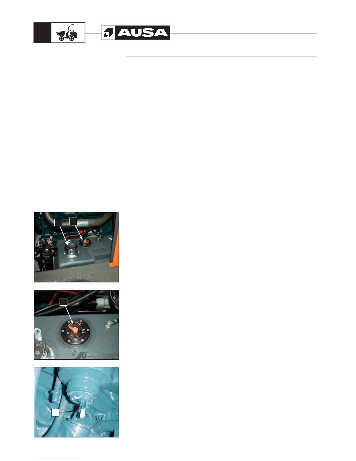
Fuel level (fig. 1, 2)
The fuel tank is located on the right side of the engine compartment.
There is an indicator dial which shows the approximate amount of fuel in the tank.
a. Fuel level indicator dial.
b. Fuel filling cap.
Draining water from the filter element (fig. 3)
The fuel used in this vehicle may contain water which is deposited at the bottom of the
filter element. It is vitally important for the protection of the engine injection system to
drain the water from the filter element at the frequency indicated in the LUBRICATION
AND MAINTENANCE CHART.
Loosen the drain (c) located at the bottom of the filter. Wait until all water has been
released and retighten the drain.
WARNING!!
Take care to correctly loosen the drain (c) otherwise the fuel system could take in air
causing engine failure.
a
a
b
c
Page 41
D 900 AP / D 1000 AP / D 1000 APG
39
(fi g. 1)(fi g. 2)
WARNING
Always stop the engine before refuelling. Open the cap slowly. If you notice
internal pressure (whistling sound heard when removing the fuel tank cap) the
dumper must be inspected and/or repaired before further operation. Fuel is
flammable and explosive under certain conditions. Never use a flame to check
fuel levels.
Never smoke, light a flame or sparks in the vicinity of the fuel tank. Always work
in well ventilated areas. Never fill up the fuel tank before placing the vehicle
in a hot area. When temperature increases, fuel expands. If the fuel tank is
completely full it may overflow. Always clean any fuel or oil spillage from the
vehicle.
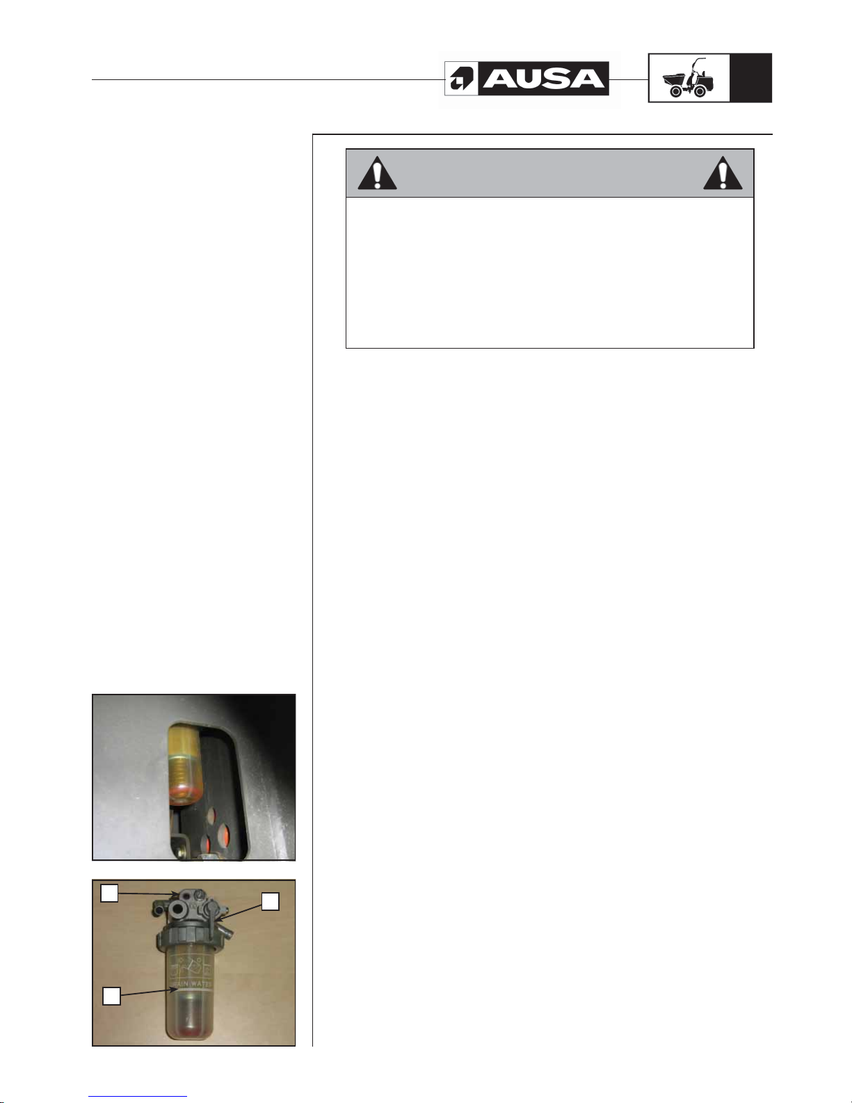
Water separator (fig. 1, 2)
This is located at the rear of the machine, in the left wheel arch.(fig. 1)
a. Support
b. Deposit
c. T ap
The fuel used may contain water which is deposited inside the deposit (b) of the
water tank which is located between the pre-filter and the electric fuel pump. It is of
vital importance in order to protect the injection system, that the water is emptied
and the elements are cleaned at the intervals indicated on the LUBRICATION AND
MAINTENANCE CHART or when the level float (red washer) reaches the maximum
level indicated in the deposit.
To do so:
- Close the tap (c) located at the fuel entry point
- Loosen the deposit (b).
- Empty the water.
- Clean the mesh filter with a brush and clean diesel.
- Replace the elements in reverse order.
WARNING!!
Before starting the engine, open the tap once again (c).
Periodic
maintenance
operations
a
c
b
Page 42
D 900 AP / D 1000 AP / D 1000 APG
40
(fi g. 3) (fi g. 2) (fi g. 1)
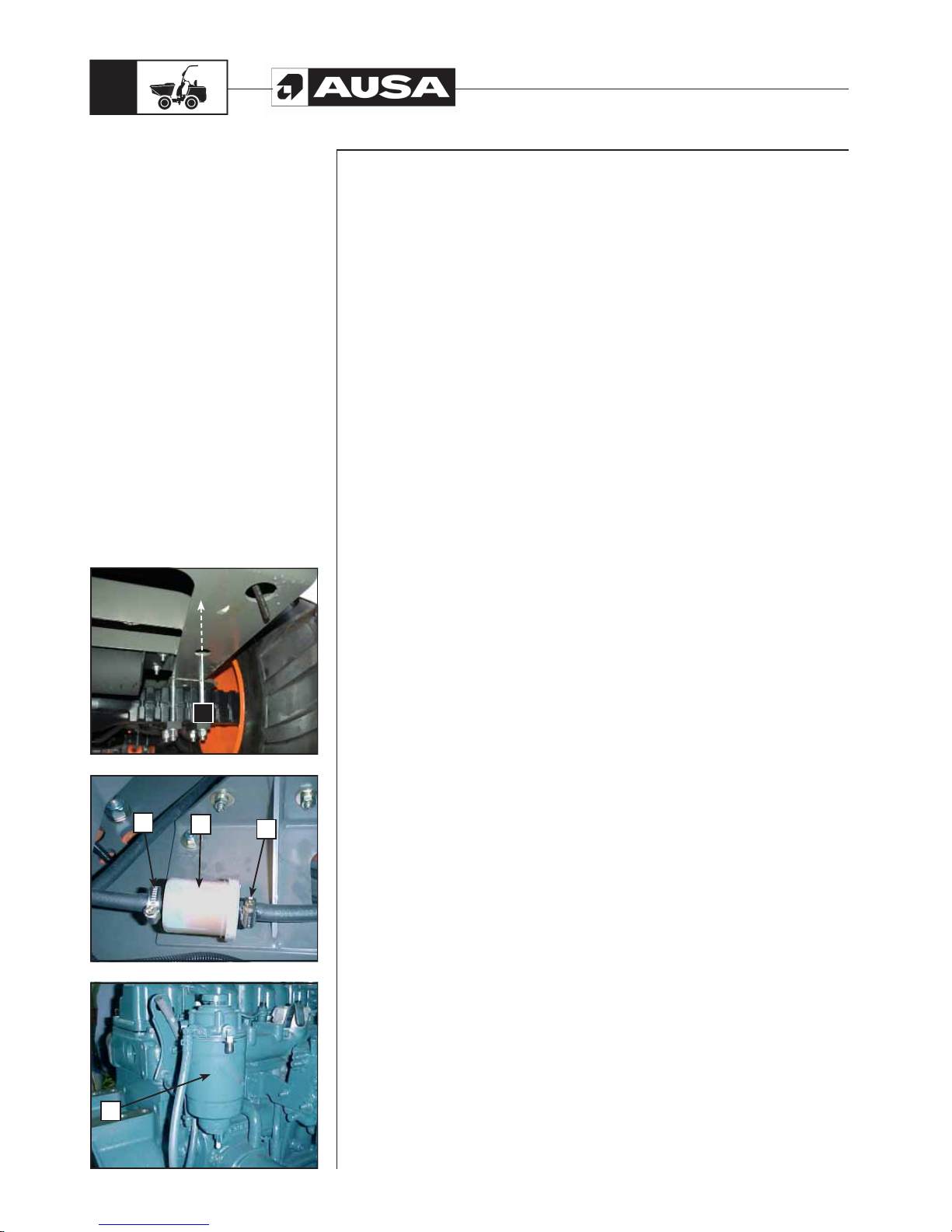
Draining the fuel tank (fig. 1)
d. Fuel tank drainage cap
Draining fuel is done via the cap situated on the lower part of the tank.
- Clean the area around the fuel drainage cap.
- Place a container underneath the fuel drainage cap.
- Unscrew the cap.
- Change the joint in the fuel drainage cap. Clean the tank joint area and the oil
drainage cap and replace the cap.
Ensure that there are no leaks from the fuel drainage cap.
WARNING!!
Clean any fuel spillage.
Changing the fuel pre-filter (fig. 2)
NOTE: Always replace this component. Under no circumstances should you attempt
to clean it.
Access the lower rear of the dumper under the engine counterweight as follows:
e. Pre-filter
f. Flanges
Remove the fixing flanges and the filter . Ensure that the new filter is located in the correct
direction as indicated by the arrow marked on the filter housing.
Changing the fuel filter (fig. 3)
Unscrew the fuel filter cartridge located on the left part of the engine and remove it from
its support.
g. Fuel filter
Clean the base and cover the joint of the new filter with clean oil. Screw in the filter
element once again and tighten, do not use mechanical tools.
Fuel system purge.
If the fuel system has taken in air , purging is not necessary as it has a system for expelling
air from the circuit.
Periodic
maintenance
operations
f
e
f
g
a
Page 43
D 900 AP / D 1000 AP / D 1000 APG
41
(fi g. 3) (fi g. 2) (fi g. 1)
3.- Engine oil
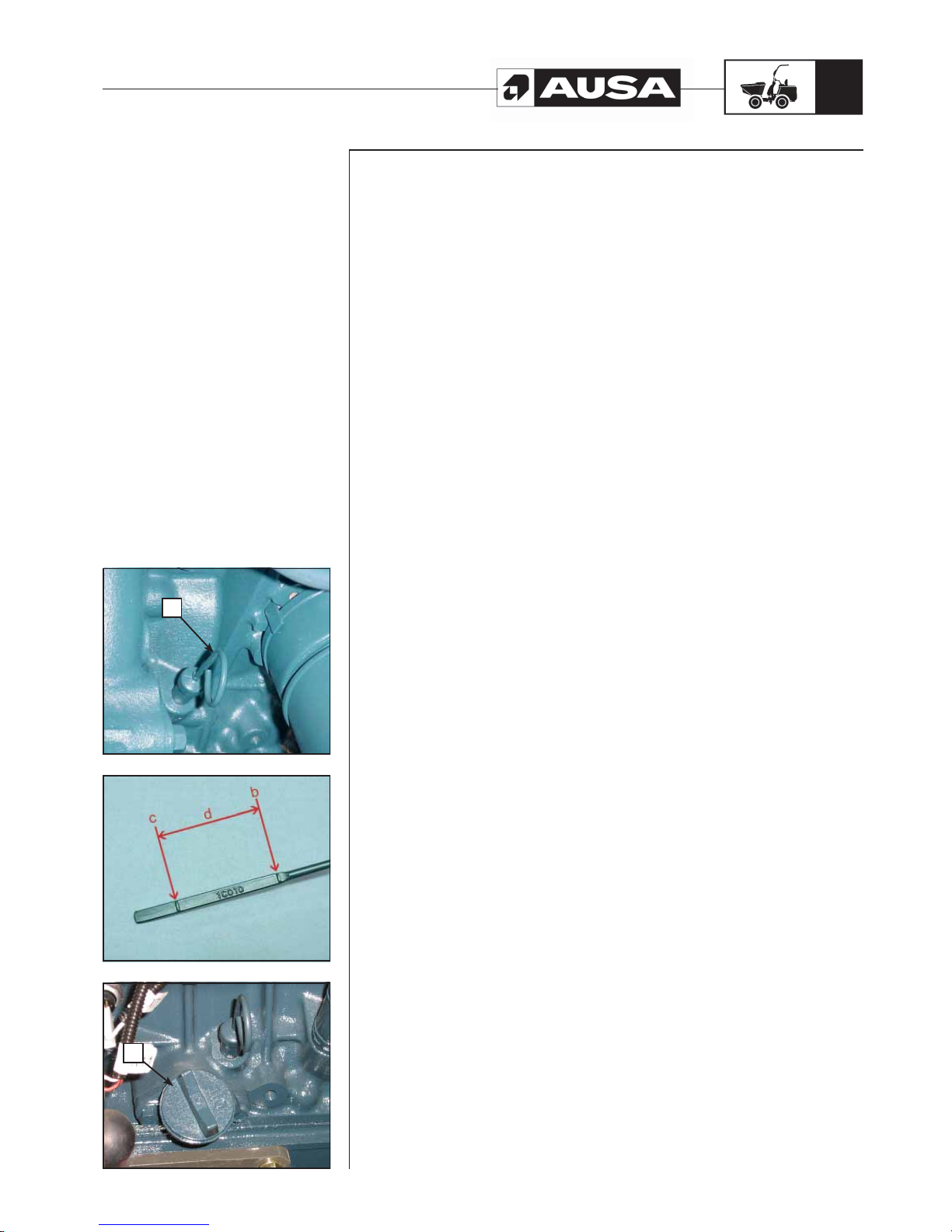
Engine oil level (fig. 1, 2, 3)
CAUTION:
Frequently check the level and refill if necessary. Do not exceed the maximum level.
Operating the engine with an inappropriate oil level could severely damage the engine.
Clean any spills.
With the vehicle on a level surface and the engine stopped and cold, check the oil level
in the following way.
a. Dipstick
- Pull the oil level dipstick (a), remove it from its housing and clean it with a clean
cloth (fig. 1).
- Place the dipstick in its housing.
- Remove it once again from the housing and check the oil level. It must be up to
or equal to the upper level marked (fig. 2).
b. Full
c. Add
d. Operating range
- Add oil up to the upper level mark if required.
- T o add oil, remove the oil level dipstick. Place a funnel in the oil filling hole located
to the right side of the engine.
e. Filling hole (fig. 3)
Do not exceed the maximum level.
- Properly cover the oil filling hole and correctly store the oil level dipstick.
Periodic
maintenance
operations
a
e
Page 44
D 900 AP / D 1000 AP / D 1000 APG
42
(fi g. 1)(fi g. 2)
Periodic
maintenance
operations
Changing the oil and the oil filter (fig.1, 2)
Changing the oil and the oil filter should be carried out at the intervals indicated in the
LUBRICATION AND MAINTENANCE CHART in this Manual.
WARNING!!
The first engine oil change should be carried out at the 50 hour service. Initial maintenance
is very important and must not be neglected.
f. Oil drainage hose (fig. 1)
- Oil changes should be carried out when the oil is warm.
- Secure the dumper on a level surface.
- Remove the dipstick.
- Clean the oil drainage hose area.
- Place a container underneath the oil drainage hose.
- Loosen the cap at the end of the oil drainage hose.
- Allow the oil to drain for a while.
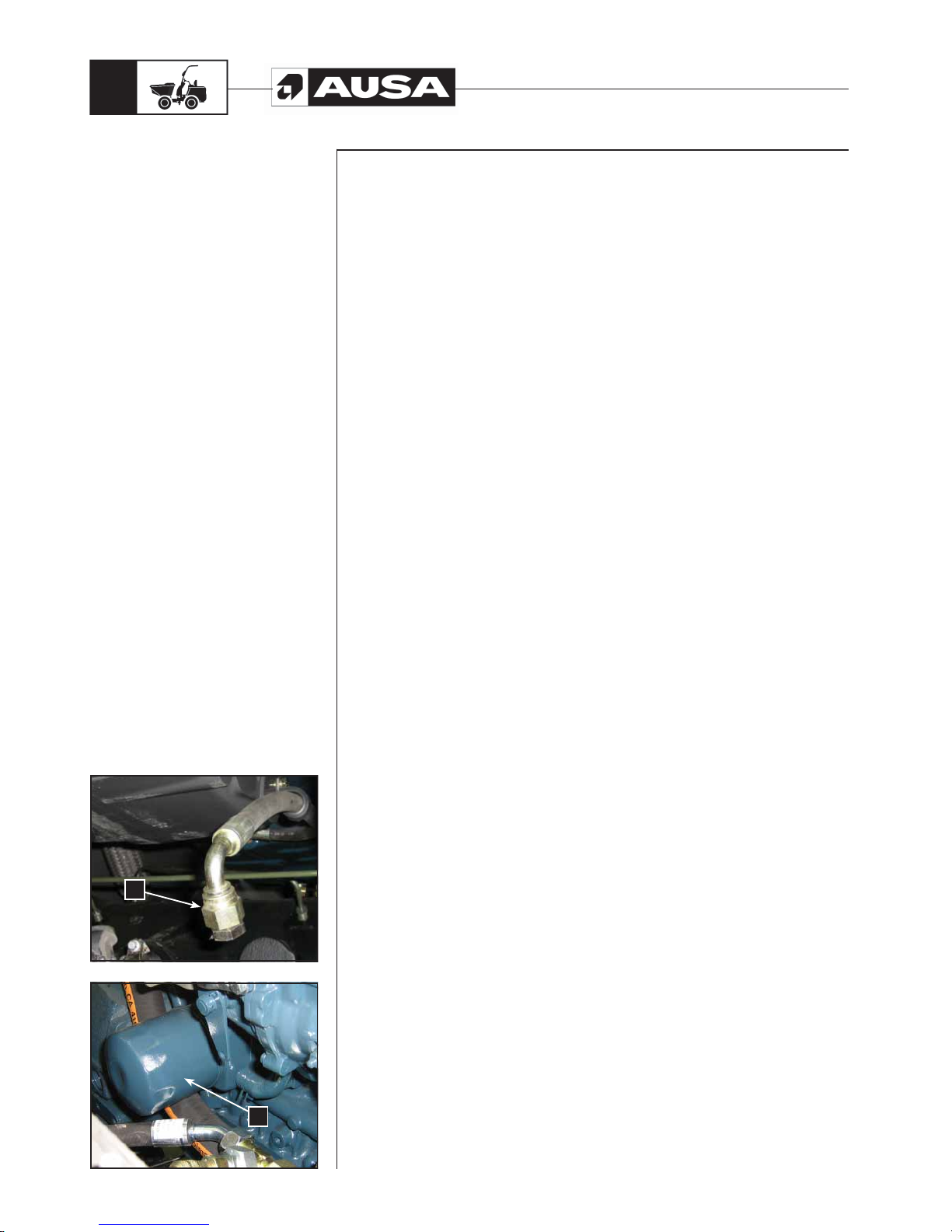
- Unscrew the oil filter cartridge located on the left side and remove it from its
support.
g. Oil filter cartridge (fig. 2)
Clean the base and cover the joint of the new filter element with clean oil.
Screw in the filter element once again and tighten by hand; do not use mechanical tools.
WARNING!!
- Clean any oil spill on the engine.
- Clean the oil drainage hose area.
- Refill the engine as per the recommended oil level.
- See the LIQUIDS AND LUBRICANTS section of the Manual for capacities.
- Start the engine and leave running idle for a few minutes.
- Ensure that there are no leaks in any of the oil filter areas and on the oil drainage
cap.
- Stop the engine.
- Wait a few moments to allow the oil to flow towards the engine crankcase and
then check the oil level.
- Refill if necessary.
- Dispose of the oil in appropriately authorised centres.
f
g
Page 45
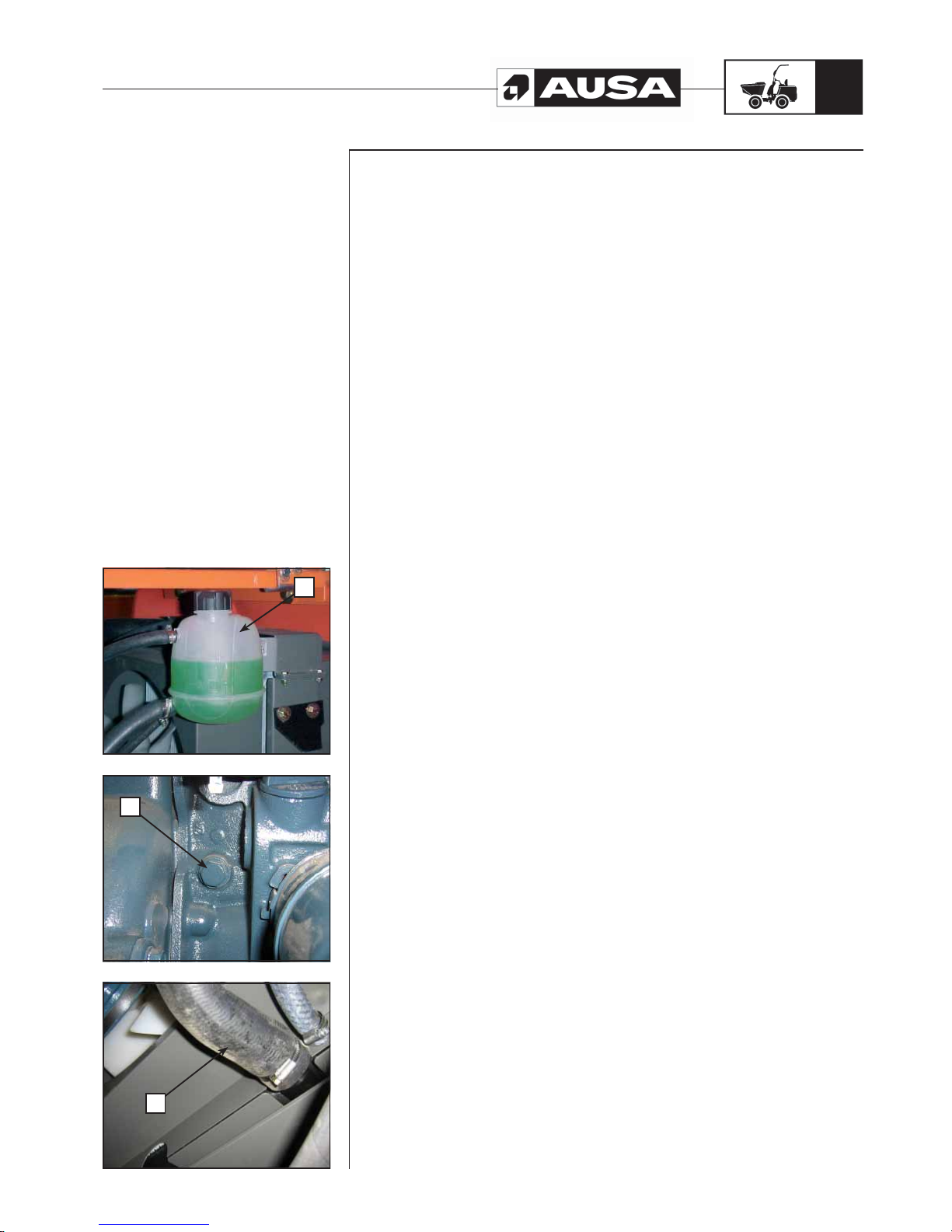
D 900 AP / D 1000 AP / D 1000 APG
43
(fi g. 2)(fi g. 3) (fi g. 1)
4.- Engine cooling system
Consult the LIQUIDS AND LUBRICANTS section of this Manual for the
SPECIFICATIONS of the coolant liquid to be used.
WARNING!!
Never remove the reservoir cap if the engine is hot. Wait until the engine is cold. Wait for
approximately 20 minutes.
Coolant liquid level (fig. 1)
Check the level in the expansion tank.
a. Reservoir
Remove the maintenance access cover located to the side of the operator’s seat.
With the vehicle on a level surface, the liquid must be between the MIN. and MAX. levels
marked on the reservoir.
NOTE: When checking the level at a temperature lower than 20°C (68°F), the level may
be below the MIN mark.
Add coolant up to MAX. mark if required. Never exceed the maximum level.
Use a funnel to avoid spills.
Replace and correctly tighten the filling cap and replace the maintenance access panel.
NOTE: A cooling system which requires coolant frequently indicates that there are leaks
or engine problems. See an authorised AUSA dealer.
Changing the coolant (fig. 2, 3)
b. Cylinder block drainage cap.
c. Lower radiator hose.
This change should be carries out every 1000 hours or when the circuit is emptied for
repair. To do so the following operations are carried out:
- Loosen the cylinder block drainage cap, located on the left side of the engine, to
drain it.
- Disconnect the lower radiator hose in order to empty the radiator at this point.
- Before filling the circuit the engine drainage cap must be tightened and the hose
must be connected again.
- Filling is carried out using the upper radiator cap and the reservoir.
- Start the engine and wait until the thermostat is open.
- Then with the engine cold, check the level in the reservoir.
Check the intervals for replacing the filter in the LUBRICATION AND MAINTENANCE
CHART or replace when the circuit must be drained for repair.
Periodic
maintenance
operations
a
b
c
Page 46
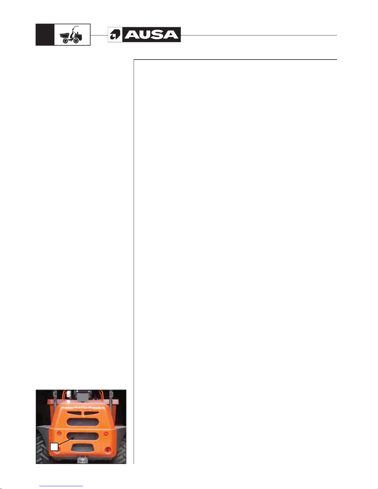
D 900 AP / D 1000 AP / D 1000 APG
44
(fi g. 1)
Radiator (fig. 1)
d. Radiator fins
Periodically check the radiator area to ensure it is clean.
Inspect the radiator fins. They must be clean, free of mud, dirt, leaves or any other
deposit that would prevent the radiator cooling properly. Never clean the radiator with
your bare hands when it is hot. Use gloves to remove external residues from the radiator .
Allow the radiator to cool before cleaning.
If water is available in the proximity, rinse the radiator fins with a hose.
Be careful not to damage the radiator when cleaning the fins. Do not use any object or
tool that could damage the fins. The fins are thin parts which therefore allow the radiator
to cool correctly.
See an authorised AUSA dealer to check the correct performance of the cooling system.
Periodic
maintenance
operations
d
Page 47
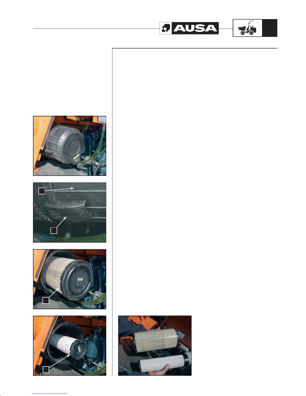
D 900 AP / D 1000 AP / D 1000 APG
45
(fi g. 4) (fi g. 3) (fi g. 2) (fi g. 1)
5.- Air intake system
Cleaning the air filter (fig. 1)
The air intake to the engine is done via a double element dry filter.
The life and performance of the engine largely depends on the correct maintenance of
this filter.
Check the intervals for replacing the filter in the LUBRICATION AND MAINTENANCE
CHART.
The internal element of the filter must be replaced on every second replacement of the
outer element.
NOTE: If the dumper is used in dusty areas, inspect more frequently than specified in
the LUBRICATION AND MAINTENANCE CHART.
NOTE: The air filter incorporates an obstruction indicator (vacumeter). If the control
lamp in the front instrument panel is lit, the filter element must be cleaned or replaced
as soon as possible.
CAUTION:
Do not start the engine when water is found in the air filter box.
When liquids or residues are found, the air filter must be inspected, dried or replaced
independently of the condition in which it is found.
Remove the air filter as explained below.
Removing the air filter (fig. 2, 3, 4, 5)
CAUTION:
Never remove or modify any filter component. Otherwise poor performance or engine
damage could occur.
Access the filter via the left side cover.
a. Clamps
b. Housing
c. Outer filter element
d. Internal filter element
Loosen the clamps of the filter housing and remove the filter elements. Clean the filter
elements of the accumulated dust and dirt, by blowing with pressurised air (maximum 5
bar) from inside out whilst turning.
Also clean inside the filter housing.
Installing the air filter.
Properly install the parts in the reverse order to their removal.
Periodic
maintenance
operations
(fi g. 5)
b
a
c
d
Page 48
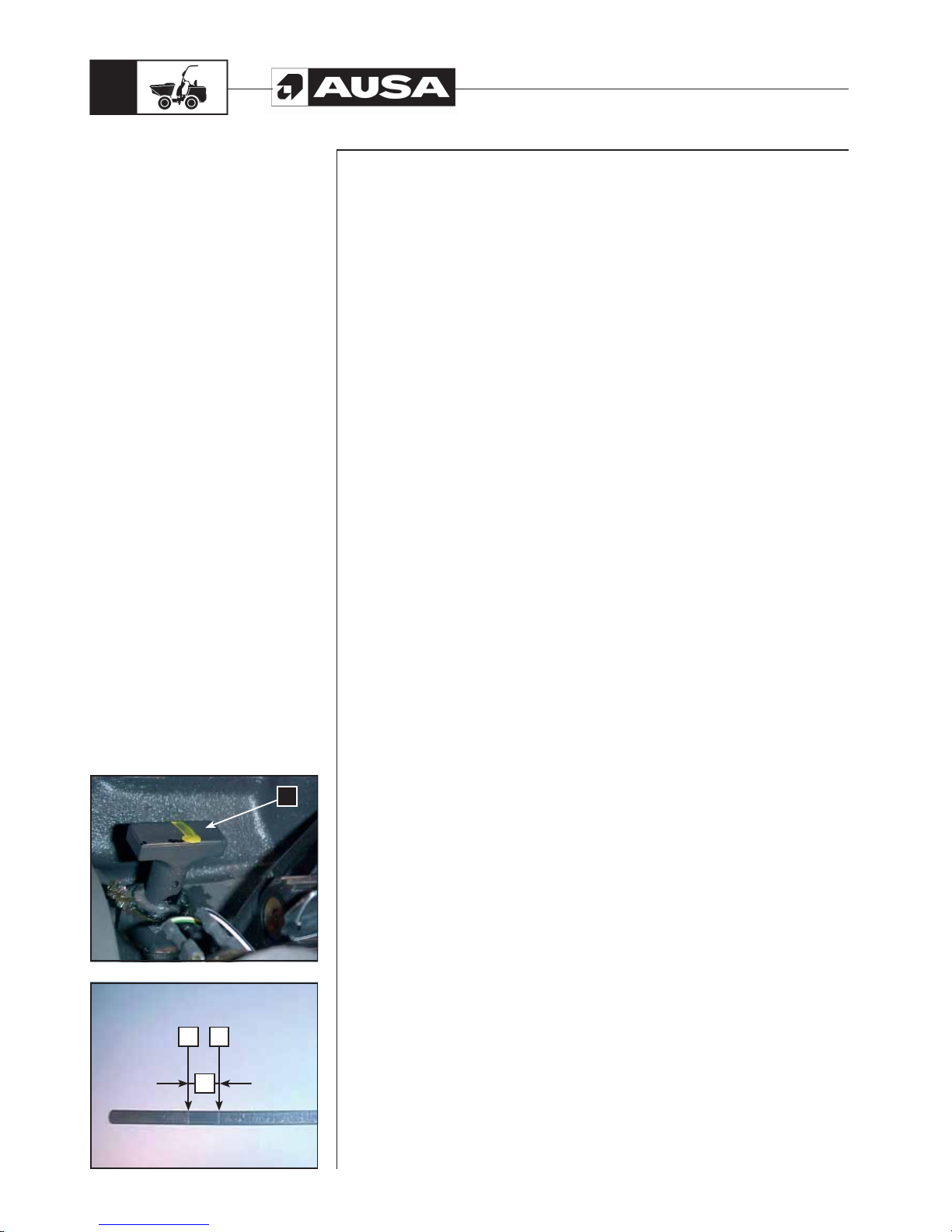
D 900 AP / D 1000 AP / D 1000 APG
46
(fi g. 1)(fi g. 2)
6.- Gearbox and converter
Gearbox and converter oil level (fig.1, 2)
Remove the dumper floor panel and access the upper part of the gearbox and the
converter.
a. Dipstick
Clean any spills.
With the vehicle on a level surface, the engine stopped and the oil cold, check the oil
level in the following way.
- Pull the oil level dipstick (a), remove it from its housing and clean it with a clean
cloth.
- Place the dipstick in its housing.
- Remove it once again from the housing and check the oil level. It must be up to
or equal to the upper level marked (fig. 2).
b. Full
c. Add
d. Operating range
- Add oil up to the upper level mark if required.
- To add oil, remove the dipstick and place a funnel in the same hole.
Do not exceed the maximum level.
- Correctly replace the dipstick.
Periodic
maintenance
operations
a
c
b
d
Page 49
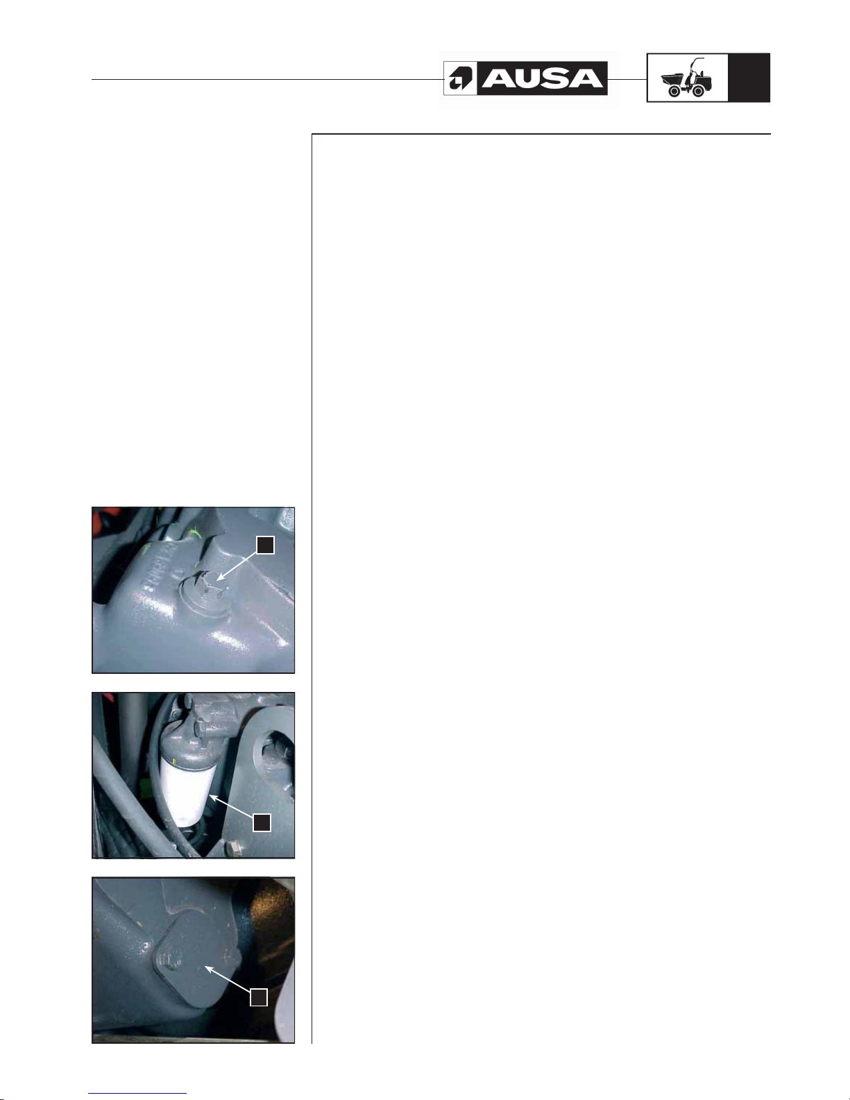
D 900 AP / D 1000 AP / D 1000 APG
47
(fi g. 3) (fi g. 2) (fi g. 1)
Periodic
maintenance
operations
Changing the oil and the filter cartridge of the gearbox and converter.
(fig.1, 2)
WARNING!!
The first replacement of oil and filter cartridge for the gearbox and converter should take
place after 50 hours of service. Initial maintenance is very important and must not be
neglected.
- Oil changes should be carried out when the oil is warm.
- Secure the dumper on a level surface.
- Remove the dipstick.
- Clean the area around the oil drainage cap.
- Place a container underneath the oil drainage cap.
- Unscrew the oil drainage cap.
e. Oil drainage cap
Allow the oil to drain for a while.
Unscrew the filter cartridge located on the right side of the gearbox and converter and
remove it from its support.
f. Oil filter cartridge.
Clean the base and cover the joint of the new filter element with clean oil.
Screw in the filter element once again and tighten by hand; do not use mechanical tools.
WARNING!!
- Clean any oil spillage.
- Change the joint in the oil drainage cap.
- Clean the area around the gearbox and converter, the oil drainage cap and
replace the cap.
- Refill the gearbox and converter as per the recommended oil level.
- See the LIQUIDS AND LUBRICANTS section of the Manual for capacities.
- Ensure that there are no leaks in any of the oil filter areas and on the oil drainage
cap.
Suction filter (fig. 3)
WARNING!!
The first cleaning of the suction filter for the gearbox and converter should take place
after 50 hours of service. Initial maintenance is very important and must not be neglected.
To extract the filter, unscrew the two screws which secure the cover.
Once extracted, it must be thoroughly cleaned and dried.
g. Suction filter
Once clean, place the filter inside its housing once again.
Fix the cover, replacing the seals for new ones.
e
f
g
Page 50
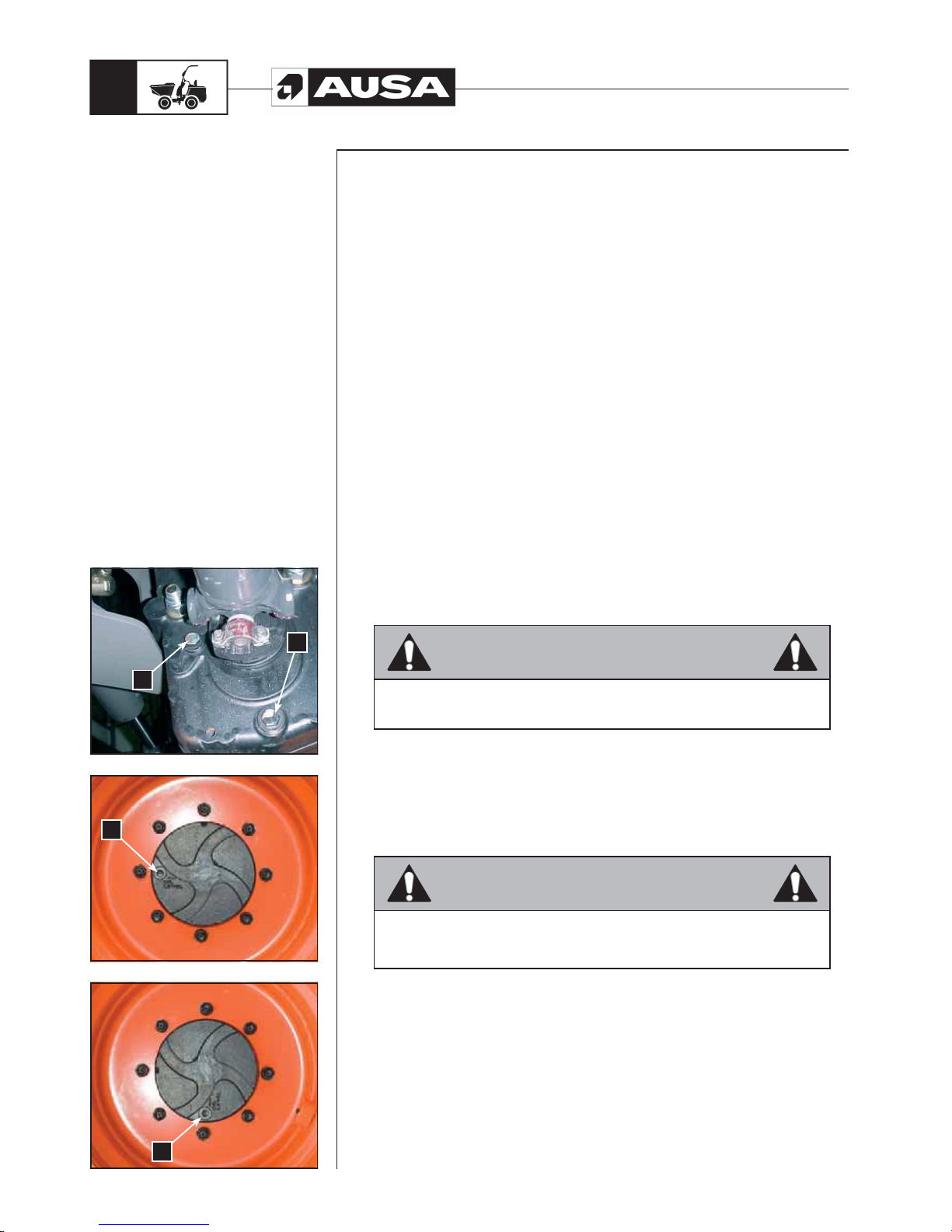
D 900 AP / D 1000 AP / D 1000 APG
48
(fi g. 1)(fi g. 1)(fi g. 1)
Periodic
maintenance
operations
7.- Transfer box
Transfer box oil level (fig. 1)
a. Level cap
With the dumper on a level surface, check the oil level in the following way:
- Unscrew the level cap. The oil should spill out of the hole.
- If necessary, add oil through the same level hole.
Changing the transfer box oil
Oil changes should be carried out when the oil is warm.
- Clean the area around the drainage cap.
- Place a container underneath the oil drainage cap.
- Unscrew the oil drainage cap.
b. Oil drainage cap
- Change the joint in the oil drainage cap.
- Clean the reducer box joint area, the oil drainage cap and replace the cap.
- Refill the reducer box as per the recommended oil level. See the LIQUIDS AND
LUBRICANTS section of the Manual for capacities.
- Ensure that there are no leaks from the oil drainage cap.
WARNING!!
Clean any oil spillage.
Oil level in planetary reductions (fig. 2, 3)
WARNING
Never remove the drain plug of the final reductions when the oil is hot. The
gases formed in the interior may cause injury.
Planetary reduction: Checking the level
- Turn the wheel until the mark “Oil Level” on the reducer is horizontal.
- To check the oil level in the final reductions use the cap (c).
Planetary reductions: Draining
- Remove the wheel.
WARNING
If is necessary to remove the drain plug while the oil is still hot, place it on the
upper part of the wheel hub, and remove the plug carefully covering it with a
cloth or similar.
- To drain the oil, turn the wheel hub until plug (c) is located on the lower part of
the wheel hub.
Planetary reduction: Topping up
- Turn the wheel until the mark “Oil Level” on the reducer is horizontal.
- Fill with the specified oil through the opening of the plug (c).
See the FLUIDS AND LUBRICANTS CHART (references and capacities) in
this Operator’s and Safety Manual for oil specs. and capacity.
a
b
c
c
Page 51
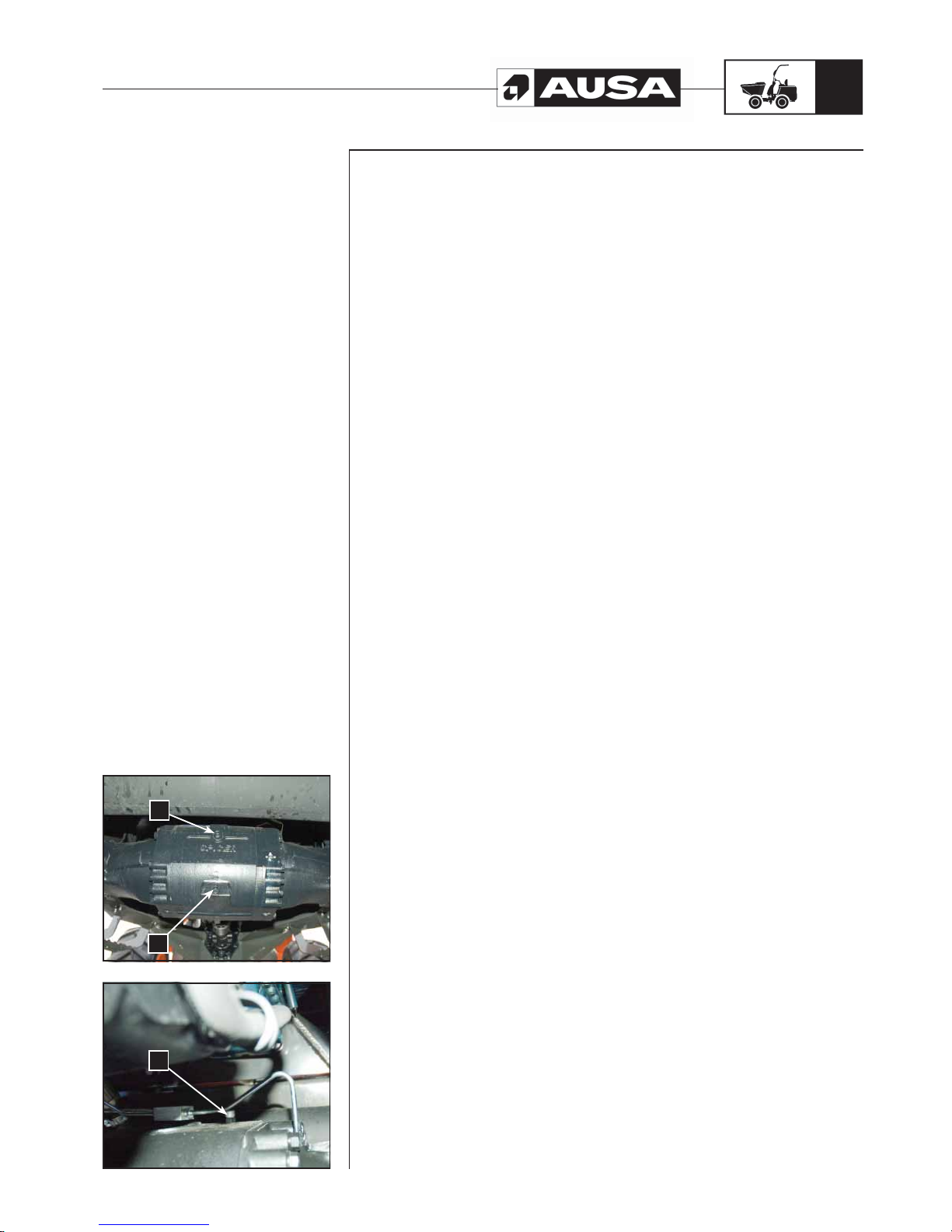
D 900 AP / D 1000 AP / D 1000 APG
49
(fi g. 1)(fi g. 2)
Periodic
maintenance
operations
8.- Differentials (fig.1, 2)
Differential oil level
a. Filling cap and devaporizer
b. Level cap
With the dumper on a level surface, check the oil level in the following way:
- Unscrew the filling cap. The oil should spill out of the hole.
- Check the oil level and add if necessary through the filling cap. The level cap and
devaporizer cap can also be used for filling differential oil.
Changing differential oil
Oil changes should be carried out when the oil is warm.
- Clean the area around the drainage cap.
- Place a container underneath the oil drainage cap.
- Unscrew the oil drainage cap.
c. Oil drainage cap
Change the seal in the oil drainage cap. Clean the shaft seal area and the oil drainage
cap and replace the cap.
Refill the differential shafts as per the recommended oil level. See the LIQUIDS AND
LUBRICANTS section of the Manual for capacities.
Ensure that there are no leaks from the oil drainage cap.
WARNING!!
Clean any oil spillage.
b
c
a
Page 52
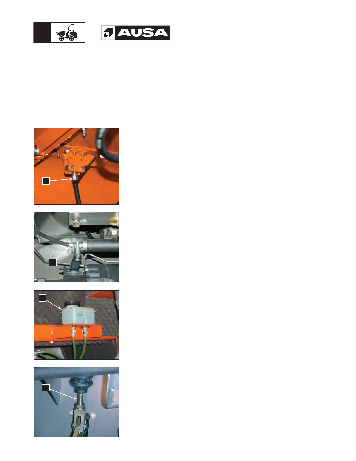
D 900 AP / D 1000 AP / D 1000 APG
50
(fi g. 3)(fi g. 4) (fi g. 2) (fi g. 1)
9.- Service and parking brake
Check the following to keep the brakes in good operating conditions.
- System fluid leaks
- Spongy feel to the pedal and no feeling of tightening
WARNING!!
Brake fluid replacement or any brake system repair should be performed by an
authorised AUSA dealer.
Parking brake (fig. 1,2)
a. Cable cover
If activating the parking brake does not immobilise the dumper, the cables must be
tightened. To do so:
- Can be tightened by both ends of the cable housing.
- Always the maintain the cables free from excessive bends and the joints greased.
Service Brake
The brakes are self-adjusting and therefore require no adjustment.
Brake fluid level (fig. 3)
The tank is located above the brake pump, under the floor panel.
With the dumper on a level surface, the brake liquid must be between the MIN. and MAX.
levels marked.
b. Brake fluid tank
NOTE: Never exceed the maximum level.
Use a funnel to avoid spills.
Place and tighten the filling cap correctly and close the cover.
NOTE: A brake system which frequently required brake fluid indicates that there are
leaks. See an authorised AUSA dealer.
Changing the brake fluid
Check the replacement schedule in the LUBRICATION AND MAINTENANCE
CHART or replace when the circuit is emptied for repairs. T o do so, contact an authorised
AUSA dealer.
Brake pump (fig. 4)
If the pedal has too much play, this can be corrected using the pedal tappet that drives
the brake pump, which has a spring system for moving it.
c. Pump tappet
Allow the pusher to have play of between 1 and 1.5 mm, ensuring that the pump has no
internal pressure.
Periodic
maintenance
operations
a
a
b
c
Page 53
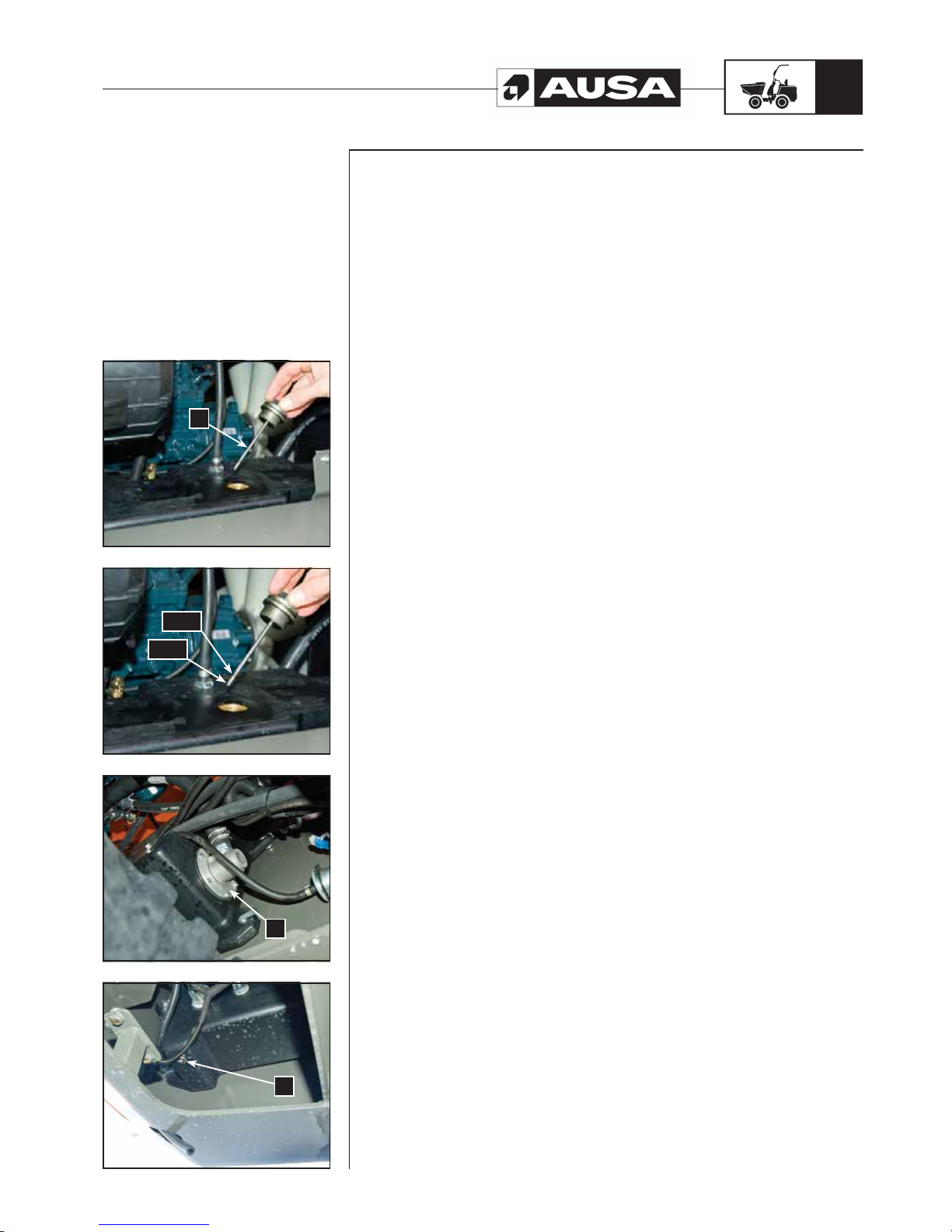
D 900 AP / D 1000 AP / D 1000 APG
51
(fi g. 4) (fi g. 3) (fi g. 2) (fi g. 1)
10.- Hydraulic Circuit
Hydraulic oil level (fig. 1, 2, )
The hydraulic oil tank is located on the left side of the engine compartment.
Place that the dumper is on a level surface.
The oil level must always be checked with the hopper in the lower position and with the
engine stopped.
a. Filling cap and dipstick
Unscrew the filling cap which includes the dipstick. The oil level should be between the
MIN. and MAX. level marks.
If necessary, add oil through the same filling hole. Use a funnel to avoid spills.
Place and tighten the filling cap correctly and close the cover.
NOTE: Never exceed the maximum level.
NOTE: A hydraulic system that requires frequent top ups indicates that there are leaks.
See an authorised AUSA dealer.
Changing the hydraulic oil (fig. 3, 4)
b. Suction filter
c. Tank drainage cap.
Draining fuel is done via the cap situated on the lower part of the tank.
Clean the area around the drainage cap.
Place a container underneath the oil drainage cap.
Unscrew the cap.
In the hydraulic circuit there is a suction filter located inside the tank. It is a metallic filter
which must be cleaned each time the hydraulic oil is replaced.
Change the seal in the oil drainage cap. Clean the tank joint area and the oil drainage
cap and replace the cap.
Refill the tank as per the recommended oil level. See the LIQUIDS AND LUBRICANTS
section of the Manual for capacities.
Ensure that there are no leaks from the oil drainage cap.
WARNING!!
Clean any oil spillage.
Periodic
maintenance
operations
MAX
MIN
a
b
c
Page 54
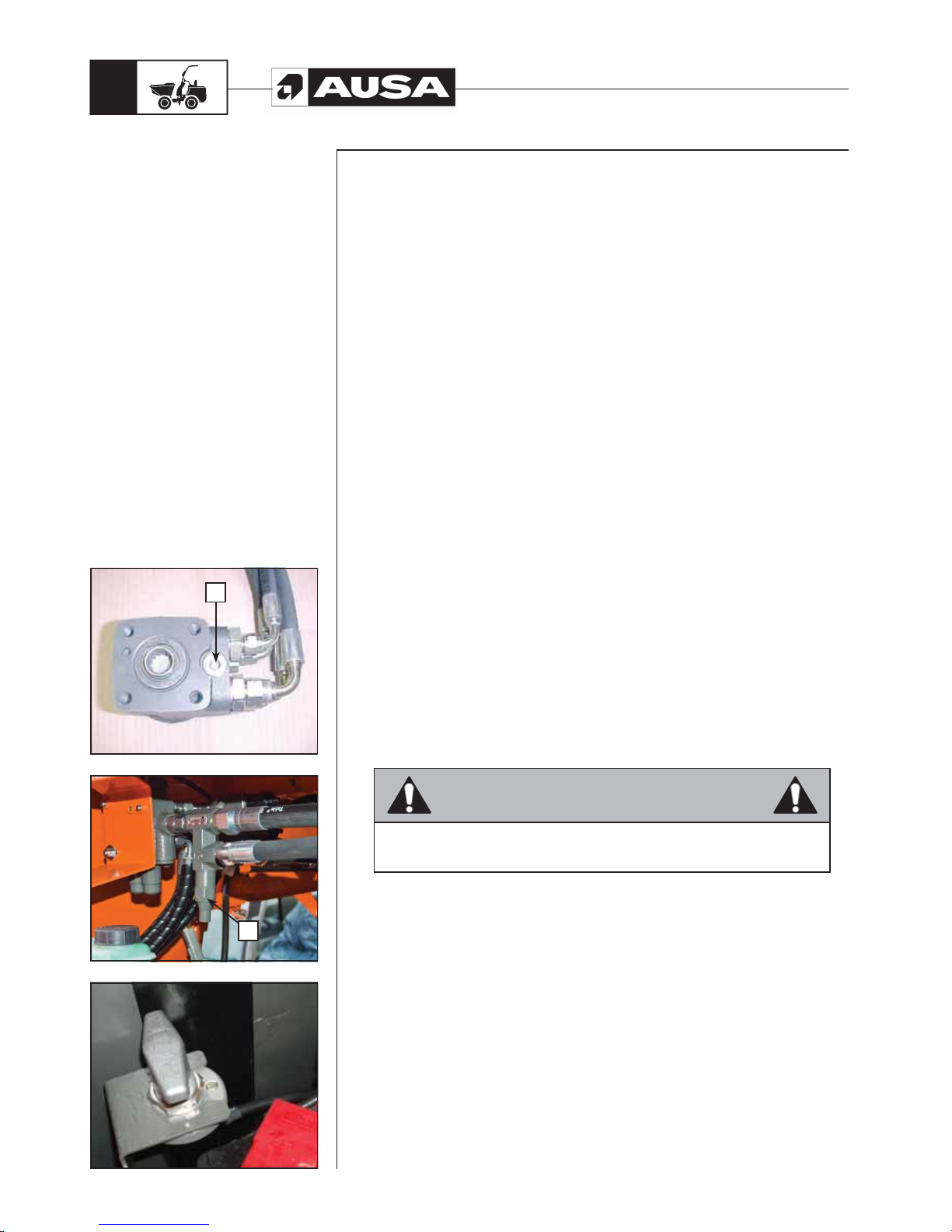
D 900 AP / D 1000 AP / D 1000 APG
52
(fi g. 2)(fi g. 3) (fi g. 1)
Adjusting the safety valves (fig. 1, 2)
There are two safety valves to avoid over pressures in the steering circuit and the load
handling systems.
a. Steering circuit safety valve
b. Load handling system safety valve
The first is located on the hydraulic steering and the second is externally connected to
the distributor.
These valves are set at the correct working pressure in factory, but the settings need to be
checked periodically and adjusted if necessary. This work must only be done by trained
mechanics with knowledge of hydraulics and with the appropriate tools. Pressures must
never exceed the limits indicated in the SPECIFICATIONS section of this manual.
- Hydraulic steering valve: Remove the cap by unscrewing it and turn the internal
screw with a screwdriver in a clockwise direction to increase the hydraulic
pressure and anti-clockwise to reduce it.
- Circuit pressure regulation valve: Remove the plastic cover, then loosen the
counter-but and turn the screw a clockwise direction to increase the hydraulic
pressure and anti-clockwise to reduce it.
Hydraulic hoses
All hydraulic hoses must be changed at least every 6 years.
11.- Electrical circuit
Battery
The battery is located in the engine compartment to the right.
Check that the battery has no external damage, lifted plates or electrolyte leaks.
Check the electrolyte density. It should have a value of between 1.27 and 1.28.
Clean the battery terminals of rust.
Apply dielectric grease or vaseline on the positive terminal to protect it from rust.
Battery disconnector (fig. 3)
There is a battery disconnector on the negative terminal (-).
Disconnection of the battery is recommended during repairs to the electrical installation,
soldering and long storage periods.
WARNING
Never charge the battery when it is mounted on the vehicle.
Periodic
maintenance
operations
a
b
Page 55
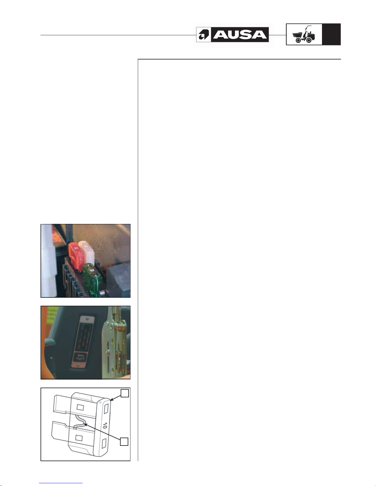
D 900 AP / D 1000 AP / D 1000 APG
53
(fi g. 2)(fi g. 3) (fi g. 1)
Fuses
If a fuse is damaged, replace it with another fuse of the same amps.
CAUTION:
Do not use fuses with higher amps, this may cause important damage. The fuses are
located in a box behind the battery and the instrument and control panel in front of the
operator.
Fuses around the battery. (fig. 1)
FG1: Instrument and control panel supply fuse (50A)
FG2: + starter relay (40A)
FG3: + glow lamps (50A)
Instrument and control panel fuses (fig. 2)
F1: Warning Lamps (7.5A)
F2: Reverse gear acoustic signal / position lights (5A)
F3: Position lights (5A)
F4: Low beam lights (10A)
F5: Road lights (10A)
F6: Joystick power (7.5A)
F7: Front / rear electrovalves + horn (10A)
F8: Starter motor / Stop solenoid (10A)
F9: Instrument and control panel lamps (7.5A)
F10: Rotating beacon (15A)
F11: Optionals fuse (10A)
To remove the fuses from the housing, remove the fuse box cover and extract the fuse.
Checking the fuses (fig. 3)
Check wither the internal filament is fused.
TYPICAL PROCESS
a. Fuse
b. Check if it is fused.
Periodic
maintenance
operations
b
a
Page 56

D 900 AP / D 1000 AP / D 1000 APG
54
12.- Wheels
Unless it is essential for the type of work to be carried out, the use of solid tyres is
not recommended, as this increase the effects of impacts on the transmission and the
operator.
Occasionally, the wheel nuts must me removed in order to apply lubricant.
This operation is very important when the dumper is used in salt water or muddy
environments. Remove the wheel nuts one by one, lubricate each one and screw them
on again.
Retighten the wheels
Weekly or every 50 hours of operation, the wheel nuts should be retightened.
Wheel nut torque loading: 425 Nm.
Tyre pressure:
WARNING!!
Tyre pressure largely effects the steering and stability of the dumper.
A low tyre pressure in the tyres could make them deflate and spin out.
A high pressure in the tyre can make it blow out. Always apply the recommended
pressure. As the tyre pressure is high, do not use a manual pump.
Inflating the wheels could be dangerous if the operation is not carried out with caution. If
possible, it is recommended that this operation be carried out by specialists in the field.
We recommend that the following instructions are followed:
- Park the dumper on flat ground with the engine off.
- Always inflate tyres when they are cold, and to the pressure indicated in the
SPECIFICATIONS section of this manual before beginning work with the
dumper.
- Tyre pressure changes according to the temperature and altitude. Recheck the
pressure if one of these conditions changes.
- Checking the pressure and inflating the tyre, must be carried out with a pressure
meter in good operational condition and equipped with a nozzle which has a
safety clamp, to avoid it slipping from the tyre valve during inflation.
- Use gloves to avoid any injury to the hands by any incorrect function of the air
nozzle.
- If the tyre is being inflated away from the dumper, first protect it with a special
protection cage designed for this purpose.
- We recommend carrying an anti-puncture repair kit with you.
Periodic
maintenance
operations
Page 57
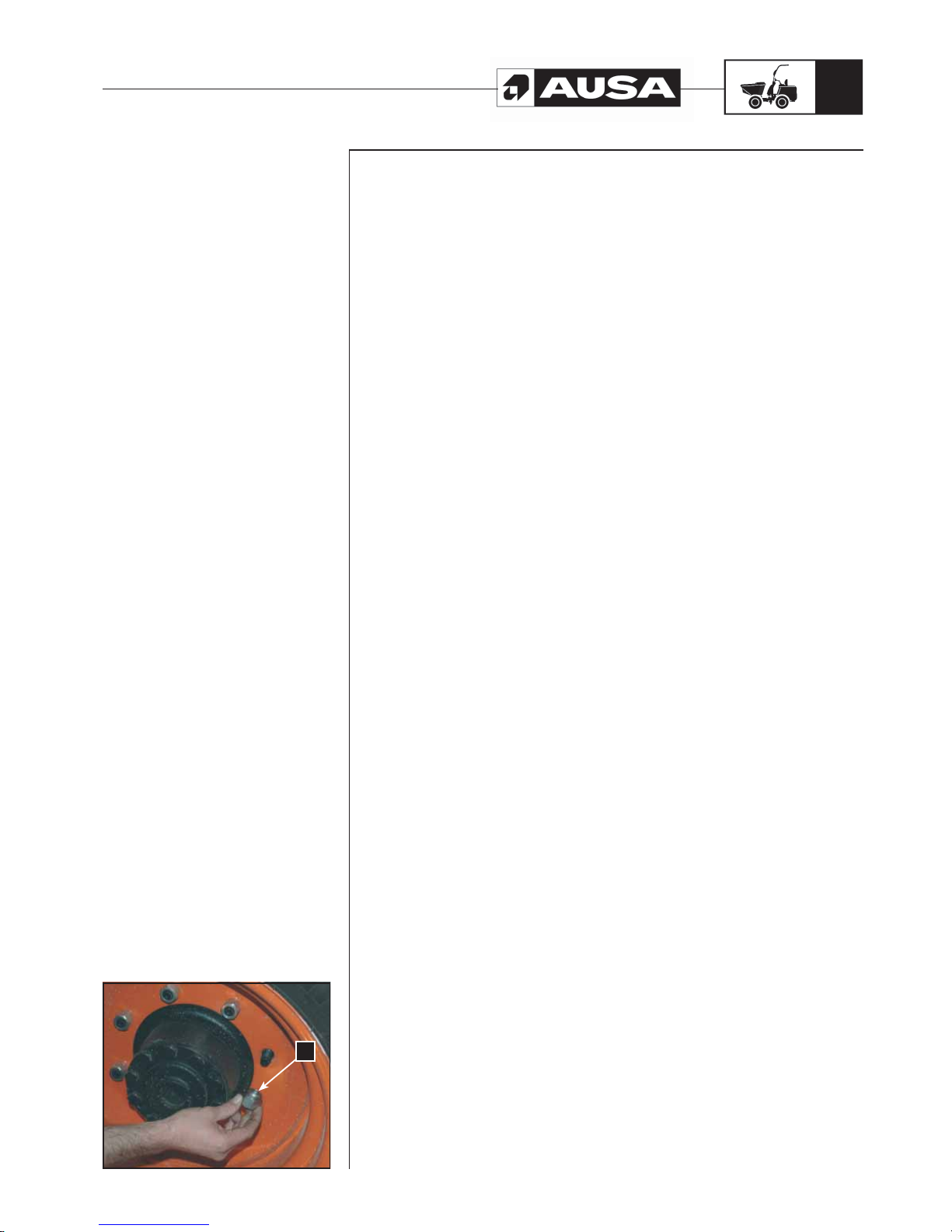
D 900 AP / D 1000 AP / D 1000 APG
55
(fi g. 1)
Wheel/Tyre condition
Check the tyres for possible damage or wear. Replace if necessary.
Do not rotate the tyres if they are directional.
For correct operation their rotation must maintain a specific direction.
Removing the wheel (fig. 1)
Loosen the nuts and raise the dumper . Place a support beneath it. Remove the nuts and
then remove the wheel.
When assembling, apply lubricant to the threads. Slowly tighten the nuts in a criss-cross
sequence, applying a final torque of 425 Nm.
a. Coned part of the wheel nut
WARNING!!
Always use the recommended wheel nuts. If you use different wheel nuts the wheel may
be damaged.
Periodic
maintenance
operations
a
Page 58
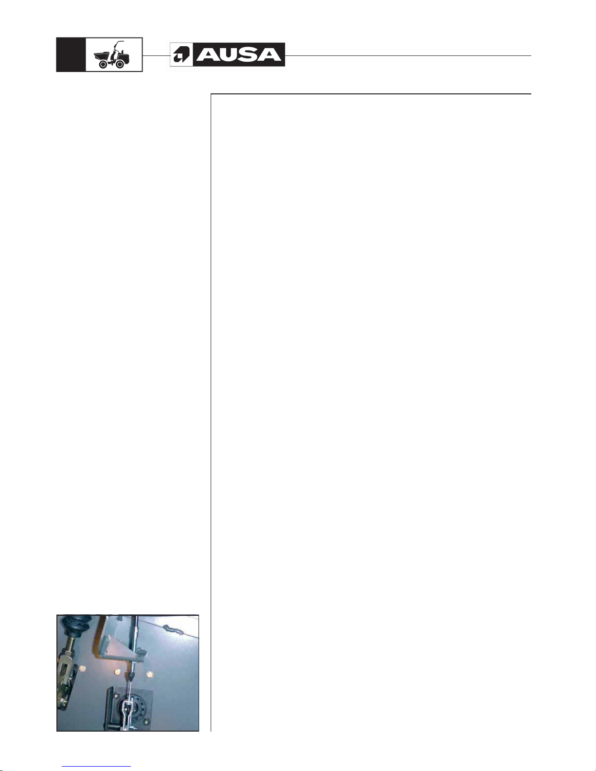
D 900 AP / D 1000 AP / D 1000 APG
56
(fi g. 1)
13.- Cable lubrication (fig. 1)
All cables must be lubricated with cable lubricant.
WARNING!!
Using another lubricant could cause the cable or control to malfunction (accelerator
pedal, etc.). Always wear eye protectors and gloves when lubricating cables.
14.- Body/Chassis
Engine Area
Check the engine compartment to see if there is any damage or leak. Ensure that all
rubber hoses are free from cuts, splits, cracks or damage of any kind and that the fittings
are correctly fitted. Examine the support devices of exhaust, battery and tanks.
Check the electrical connections for corrosion and tension on the cables.
Replace or repair damaged parts.
Chassis supports
Check the condition and tighten all dumper supports. Retighten if necessary.
Seatbelt
Check the fixture and lock of the seatbelt. Before starting the day, carefully inspect this
devices with special attention to:
- Cuts or threading on the belt
- Wear or damage to anchor points
- Poor functioning of the seat belt buckle or the retracting roller
- Loose threads or poor stitching
Consult an authorised AUSA dealer for the replacement of damaged parts.
Dumper cleaning and protection
Never use water at high pressure to clean the dumper. ONLY USE LOW PRESSURE
WATER. High pressure water can cause electrical and mechanical damage.
Damaged painted parts must be repainted to prevent corrosion.
When required, wash the body with soap and water (use only neutral soap) Apply nonabrasive wax.
CAUTION:
Never clean plastic parts with inappropriate detergent, degreasing agents, solvents,
acetone, etc.
Periodic
maintenance
operations
Page 59
D 900 AP / D 1000 AP / D 1000 APG
57
Maintenance chart
EVERY
I: Inspect, verify, clean, lubricate, replace if necessary
Initial Inspection (50 h)
125 h.
500 h.
750 h.
1000 h
1500 h.
3000 h.
Every week
Every month
Every year
Every 2 years
To be performed by
C: Clean
L: Lubricate
R: Replace
ENGINE
Oil (1) R R R USER
Oil filter (1) R R USER
Alternator Belt (1) I I R R DEALER
Valve Clearance I DEALER
Turbo charger (2) I DEALER
FUEL SYSTEM
External air filter element (4) C R(5) R USER
Internal air filter element (4) C R(5) R USER
Intake air line I R USER
Fuel pipes and clamps I I I R(2) USER
Fuel filter cartridge C R USER
Prefiltro combustible (1) R R USER
Water separator I/C USER
Fuel tank C USER
Fuel injection nozzle injection pressure (2) I DEALER
Injection pump (timing) (2) I DEALER
Fuel injection timer (2) I DEALER
COOLING SYSTEM
Radiator hoses and clamps bands I R USER
Radiator C DEALER
Coolant I R USER
POWERSHUTTLE AND TORQUE CONVERTER
Oil and filter (1) R R USER
Oil Strainer (1) C C DEALER
ELECTRICAL SYSTEM
Battery electrolyte I I USER
Battery connections I USER
Dash panel indicators / Warning lights (3) I USER
Battery I I R USER
Electric harness and loose connections I USER
HYDRAULIC CIRCUIT
Oil and strainer (3) R/C R/C I USER
Bucket functions (3) I USER
Pipes, hoses and fittings damages or leaks I USER
Hoses REPLACE EVERY 6 YEARS DEALER
Steering (3) I USER
(1) Initial inspection. The initial maintenance is very important and must not be neglected.
(2) To be performed by an authorized AUSA dealer.
(3) Daily inspection item.
(4) More often under severe use such dusty areas, sand, snow, wet or muddy conditions.
(5) Or after cleaning 6 times.
(6) Replace if it’s necessary.
Page 60
D 900 AP / D 1000 AP / D 1000 APG
58
Maintenance chart
EVERY
I: Inspect, verify, clean, lubricate, replace if necessary
Initial Inspection (50 h)
125 h.
500 h.
750 h.
1000 h
1500 h.
3000 h.
Every week
Every month
Every year
Every 2 years
To be performed by
C: Clean
L: Lubricate
R: Replace
GREASING POINTS
Central pivot L USER
Nipples (see section "Greasing points" in this Manual) L USER
Cables and articulations (throttle, lifting rams...) L USER
TRANSFER BOX
Oil (1) I R I R USER
Oil leaks I USER
Screws and nuts torque I USER
AXLES (FRONT AND REAR)
Oil (1) I R I R USER
Oil leaks I USER
Fixation wheel nuts torque I USER
Chassis fixation screws (torque) I DEALER
Cardan joint fixation screws (torque) I DEALER
Flange fixation nut (torque) I DEALER
Adjust wheel hub bearings I CLIENTE
Condition of tires and pressures I USER
BRAKES
Brake fluid (3) I R DEALER
Handbrake adjustment (3) I I USER
BODY / FRAME
ROPS frame I USER
Seat belt (3) I USER
Foot plate, access steps and handles (3) I/C USER
Guards and covers (3) I USER
Plates and decals (3) I/C USER
Central pivot nut torque I DEALER
Safety systems / articulated blocking linking bar and safety prop I USER
Engine side covers and locks (3) I USER
(1) Initial inspection. The initial maintenance is very important and must not be neglected.
(2) To be performed by an authorized AUSA dealer.
(3) Daily inspection item.
(4) More often under severe use such dusty areas, sand, snow, wet or muddy conditions.
(5) Or after cleaning 6 times.
(6) Replace if it’s necessary.
Page 61
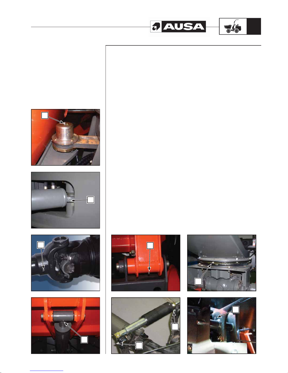
D 900 AP / D 1000 AP / D 1000 APG
59
Greasing points (fig. 1, 2, 3, 4, 5, 6, 7, 8)
6 nipples (a) on the central chassis articulation and on the tipping frame.
2 nipples (b) on the steering cylinder
3 nipples (c) on the universal drive shaft joints, one on each cross and one on the
groove.
2 nipples (d) on each drive cylinder, one on each articulation axle.
1 nipple (e) on each articulation of the cargo box lifting system
2 nipples (f) on the parking brake cable articulation on the front axle.
8 nipples (g) in the swing crown (only in D 1000 APG model)
1 nipple (h) on the brake pedal pin
See the LUBRICATION AND MAINTENANCE CHART for greasing intervals.
See the LIQUIDS AND LUBRICANTS section for the type of grease to be used.
(fi g. 4) (fi g. 3) (fi g. 1)(fi g. 2)
Greasing points
(fi g. 8) (fi g. 7)
(fi g. 6) (fi g. 5)
a
a
a
b
a
c
a
d
a
e
a
f
a
f
a
g
a
h
Page 62
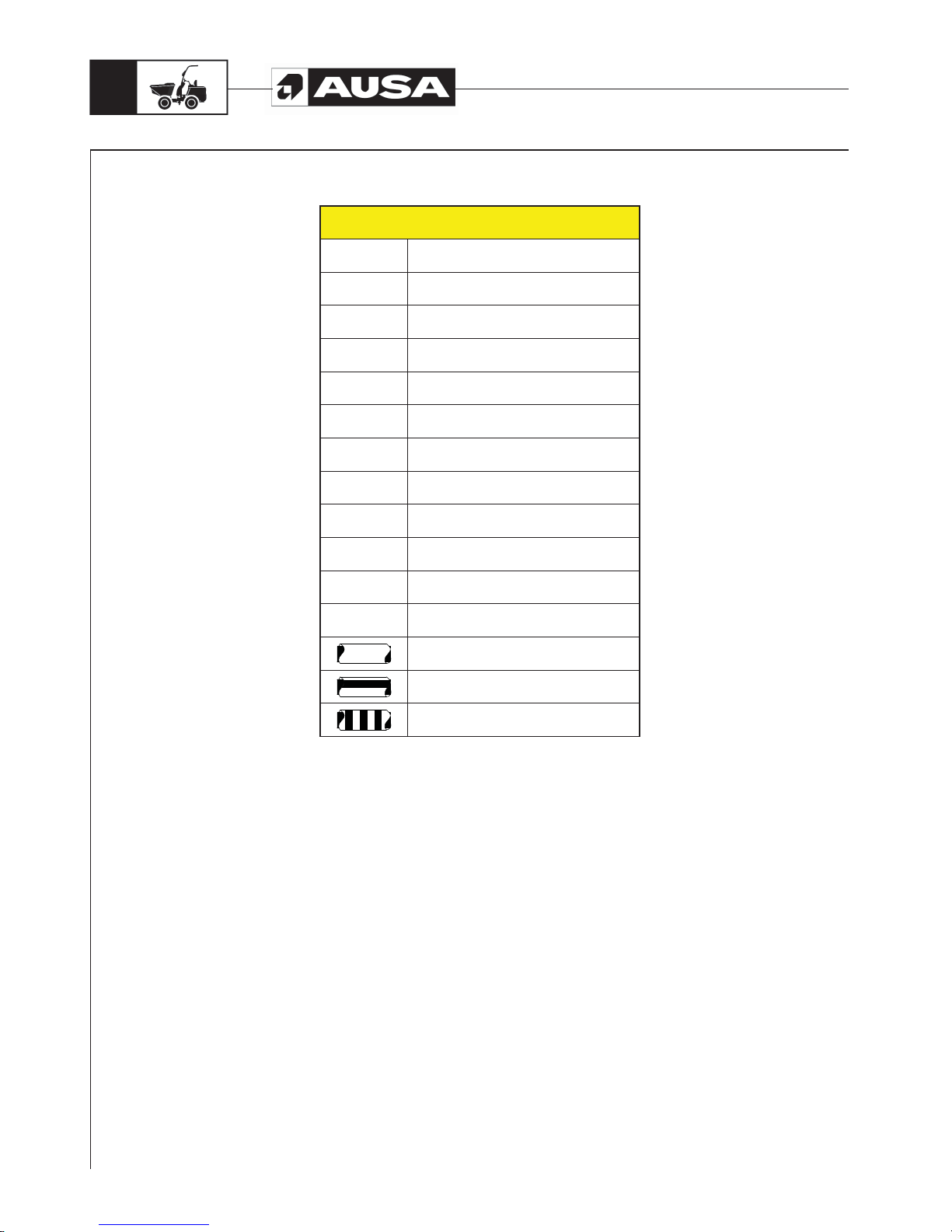
D 900 AP / D 1000 AP / D 1000 APG
60
Electric diagram
WIRE COLOURS
A Light Blue
B Withe
C Orange
G Yellow
H Gray
L Blue
M Brown
N Black
R Red
S Pink
V Green
Z Violet
Single color wire
Two lengthways colors wire
Two crossways colors wire
NOTE: The colour of the two-coloured cables is indicated by the signals painted above them.
For example:
Y/G: Yellow/Green crossways
Y-G: Yellow-Green lengthways
Page 63
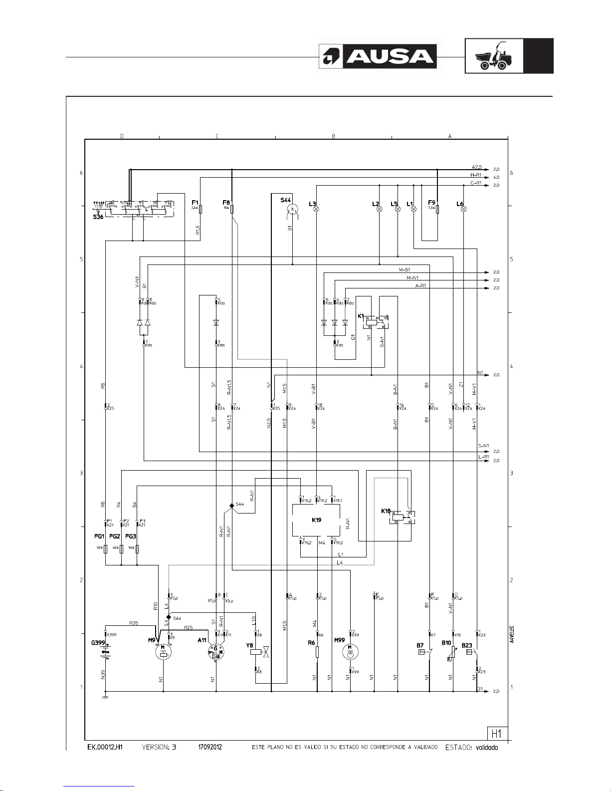
D 900 AP / D 1000 AP / D 1000 APG
61
Electric diagram H1
Page 64
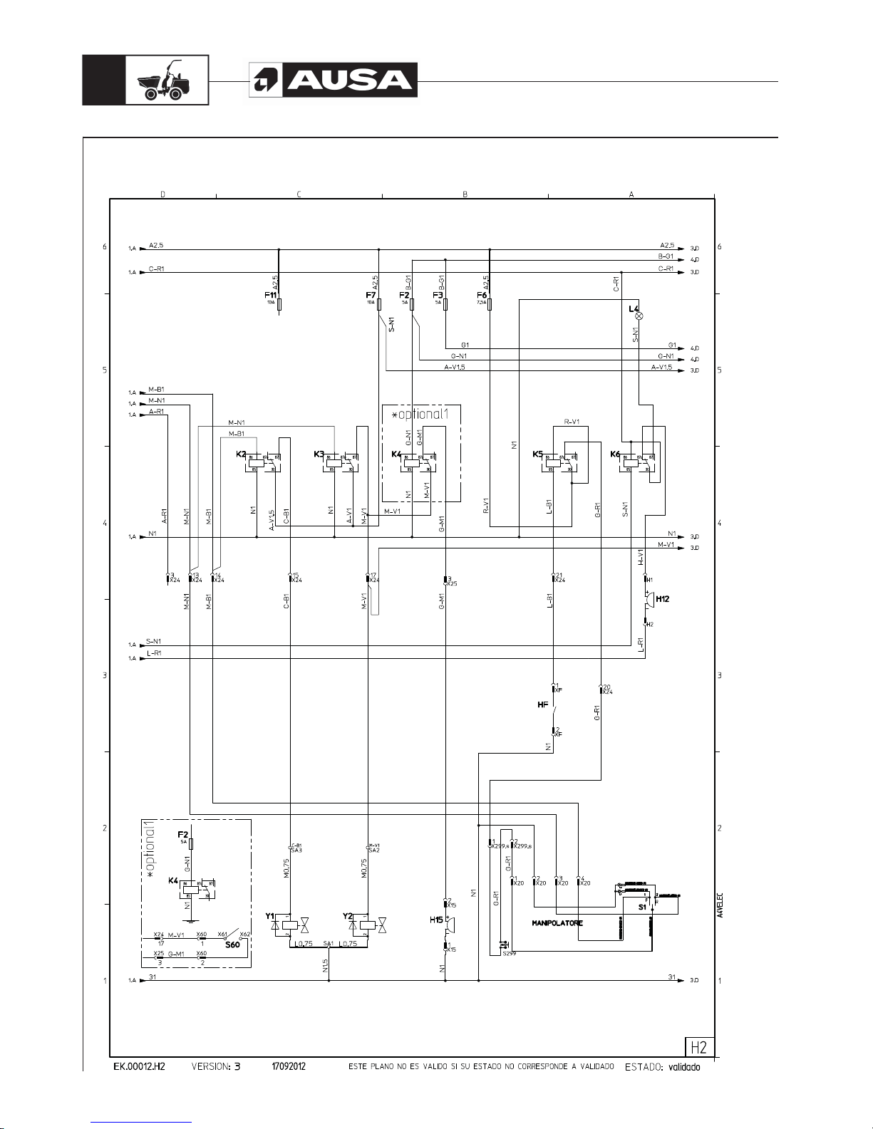
D 900 AP / D 1000 AP / D 1000 APG
62
Electric diagram H2
Page 65
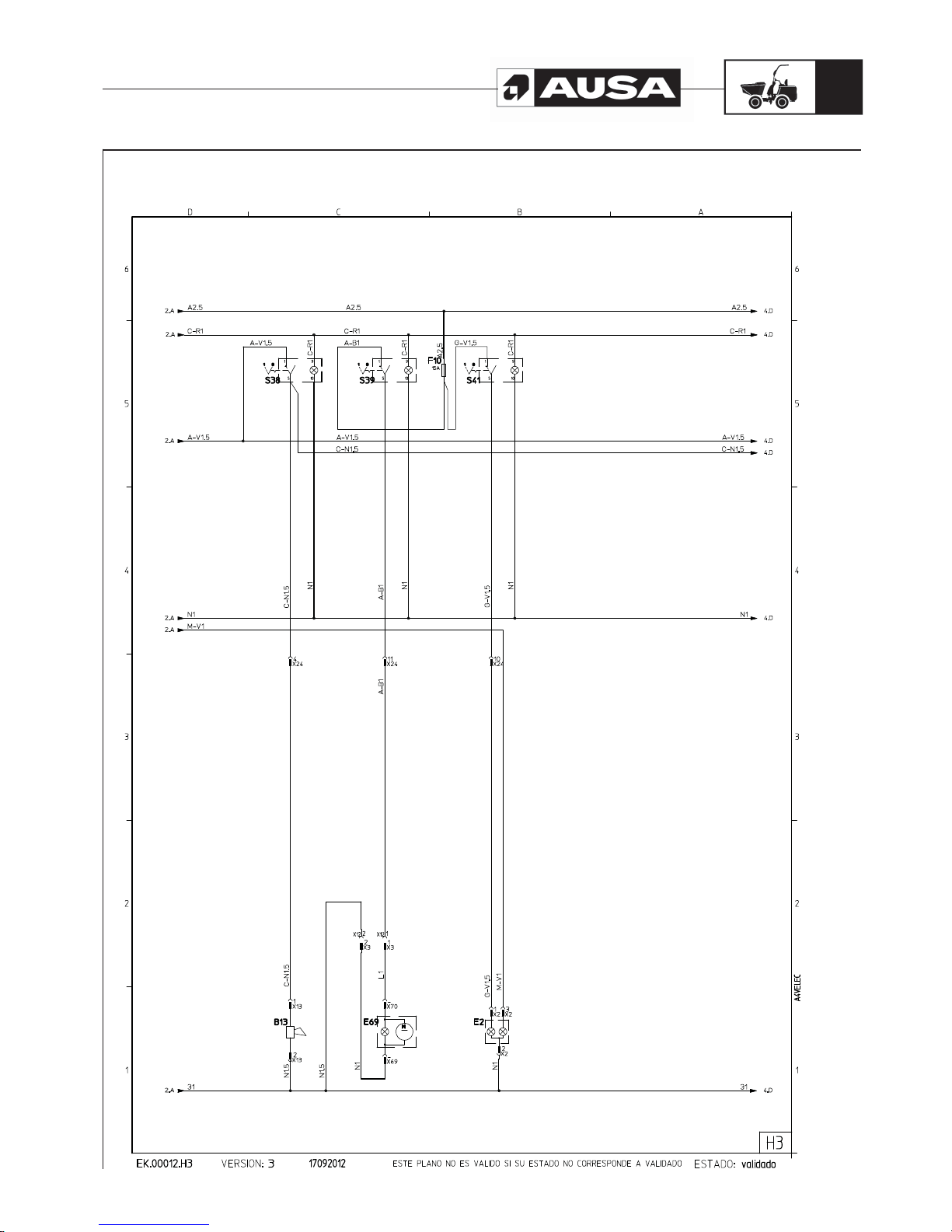
D 900 AP / D 1000 AP / D 1000 APG
63
Electric diagram H3
Page 66
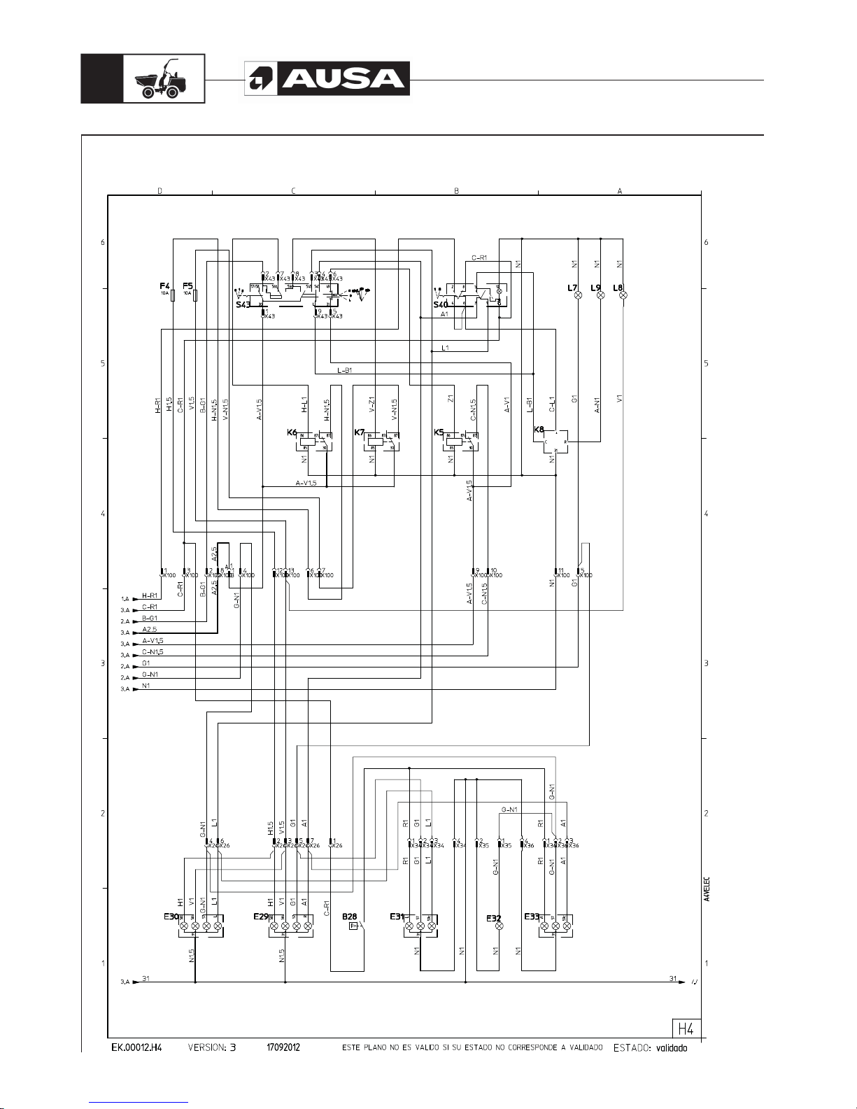
D 900 AP / D 1000 AP / D 1000 APG
64
Electric diagram H4
Page 67
D 900 AP / D 1000 AP / D 1000 APG
65
Electric diagram
Name Description Pag.
A11 Alternator 1
B7 Engine oil minimum pressure switch 1
B10 Coolant temperature warning switch 1
B13 Horn 3
B23 Air filter blockage indicator 1
B28 Brake lights pressure switch 4
E2 Working light 3
E29 Right headlight 4
E30 Left headlight 4
E31 Rear left light 4
E32 Number plate light 4
E33 Rear right light 4
E69 Rotating beacon 3
F1 (+30) warning fuse (7,5A) 1
F2 Reverse speed buzzer/left position light fuse (5A) 2
F3 Position light fuse (5A) 2
F4 Low beam fuse (10A) 4
F5 High beam fuse (10A) 4
F6 (+15) joystick fuse (7,5A) 2
F7 (+15) front and reverse solenoids + horn fuse (10A) 2
F8 (+15) starter/stop engine solenoid fuse (10A) 1
F9 (+15) warning lights fuse (7,5A) 1
F10 (+15) rotating beacon fuse (15A) 3
F11 (+15) optional fuse 10A 2
FG1 (+30) permanent live maxfuse (50A) 1
FG2 (+50) starter motor relay maxfuse (40A) 1
FG3 (+15) pre-heater relay maxfuse (50A) 1
FG4 Optional maxfuse 1
G399 Battery 1
H12 Dashboard buzzer 2
H15 Reverse relay 2
HF Parking brake sensor 2
K1 Permision start relay 1
K2 Forward relay 2
K3 Reverse relay 2
K4 Reverse alarm relay 2
Name Description Pag.
K5 Parking brake relay 2
K5 Horn relay 4
K6 Dashboard buzzer relay 2
K6 Low beam light relay 4
K7 High beam light relay 4
K8 Flasher relay 4
K18 Starter motor relay 1
K19 Pre-heating relay 1
L1 Air filter blockage warning light 1
L2 Engine oil pressure warning light 1
L3 Pre-heating warning light 1
L4 Battery charge warning light 2
L5 Coolant temperature switch warning light 1
L6 Low fuel level warning light 1
L7 Position lights warning light 4
L8 High beam warning light 4
L9 Flasher warning light 4
M9 Starter motor 1
M99 Fuel pump 1
R6 Engine pre-heating resistance 1
S1 Joystick 2
S36 Starting switch 1
S38 Horn switch 3
S39 Rotating beacon switch 3
S40 Warning switch 4
S41 Working light switch 3
S43 Steering column light switch 4
S44 Hour meter 1
S60 Disable rear gear buzzer switch (op.1) 2
S299 Shift gear push button 2
SA? Solder number ? 1/2
X?? Connector number ?? 1/2/3
Y1 Forward electrovalve 2
Y2 Reverse electrovalve 2
Y8 Engine stop solenoid 1
Page 68
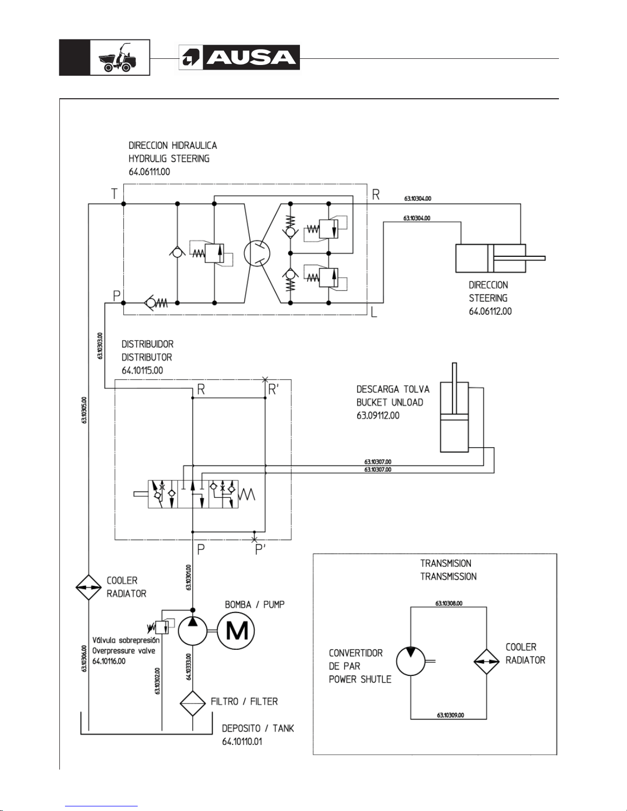
D 900 AP / D 1000 AP / D 1000 APG
66
Hydraulic diagram D 900 AP / D 1000 AP
Page 69
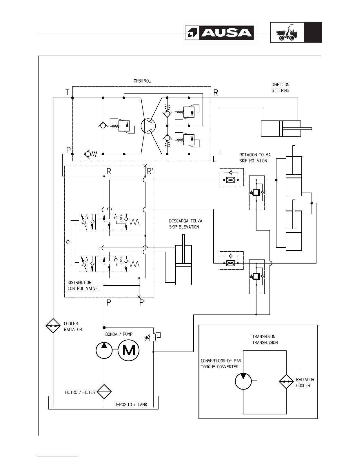
D 900 AP / D 1000 AP / D 1000 APG
67
Hydraulic diagram D 1000 APG
Page 70

AUSA Center, S.L.U. Tel. 34-93 87 47 311
Cra. de Vic, Km. 2,8 - P.O.B. 194 Fax 34-93 874 12 11
08243 MANRESA (Barcelona) España Web: http://www.ausa.com
DECLARACIÓN DE CONFORMIDAD
El fabricante AUSA Center, S.L.U. con dirección en ctra. de Vic, km 2.8, 08243 – Manresa – Barcelona
Declara que la máquina asignada a continuación:
Denominación genérica :
DUMPER
Modelo/Tipo:
D 900 AP – D 1000 AP/G
Número de serie :
XXXXXXXX
cumple todas las disposiciones aplicables de la Directiva de Máquinas, (2006/42/CE), y las reglamentaciones
nacionales que la transponen;
Real Decreto 1644/2008
cumple también con todas las disposiciones aplicables de las siguientes Directivas comunitarias:
Directiva de Compatibilidad Electromagnética, 2004/108/CE
Directivas sobre Nivel Sonoro de Equipos que Trabajan en el exterior, 2000/14/CE y 2005/88/CE
Directiva sobre Emisiones de Escape, 97/68/CE y 2004/26/CE
y las reglamentaciones nacionales que las transponen;
Real Decreto 1580/2006, aplicación de la directiva CE de Compatibilidad Electromagnética
Reales Decretos 212/2002 y 524/2006, directivas de nivel sonoro de máquinas utilizadas en el exterior
El procedimiento de certificación se ha efectuado de acuerdo con lo previsto, para las máquinas no peligrosas en las
citadas directivas.
Los datos de la persona facultada para elaborar/conservar el expediente técnico son:
D.
AUSA Center, S.L.U.
Ctra. de Vic, km 2.8, 08243 – Manresa – Barcelona
Fdo.: D.
Apoderado
Manresa, dd/mm/aaaa
Page 71

Page 72

 Loading...