

Page 1
Reference Manual &
Programming Guide
WACI NX-22
Revision 2009.09.03
Aurora Multimedia
205 Commercial Court
Morganville, NJ 07751
(732) 591-5800
(732) 591-5801 (Fax)
www.auroramultimedia.com
Page 2

© Copyright 2009, Aurora Multimedia Corp.
All rights reserved, including the right to reproduce this guide or parts thereof, in any form without the
express written permission of Aurora Multimedia, Inc.
Trademarks and registered trademarks are the properties of their respective owners. Software and hardware
features and specifications subject to change without notice.
Page 3

I. Quick Contents
3
I. QUICK CONTENTS................................................................................................................................................ 3
II. FULL CONTENTS..................................................................................................................................................4
III. INTRODUCTION..................................................................................................................................................6
IV. BOX CONTENTS.................................................................................................................................................. 7
V. HARDWARE SPECIFICATIONS........................................................................................................................ 8
VI. EXPANSION HARDWARE ..............................................................................................................................17
VII. FACTORY DEFAULT CONFIGURATIONS......................................................................................... 18
VIII. QUICK START.................................................................................................................................................19
IX. USING THE WACI..............................................................................................................................................23
X. WEB SERVER FEATURES.................................................................................................................................26
XI. BOOT MENU REFERENCE..............................................................................................................................27
XII. ADMIN WEB PAGES........................................................................................................................................31
XIII. THE EVENT MANAGER................................................................................................................................54
XIV. REMOTE PROCEDURE CALLS...................................................................................................................87
XV. LIMITED 3 YEAR WARRANTY...................................................................................................................170
XVI. FCC PART 15 STATEMENT........................................................................................................................171
XVII. INDEX.............................................................................................................................................................172
Page 4

II. Full Contents
I. QUICK CONTENTS................................................................................................................................................ 3
II. FULL CONTENTS..................................................................................................................................................4
III. INTRODUCTION..................................................................................................................................................6
IV. BOX CONTENTS.................................................................................................................................................. 7
BOX CONTENTS FOR THE NX-22......................................................................................................................................7
V. HARDWARE SPECIFICATIONS........................................................................................................................ 8
GENERAL SPECIFICATIONS................................................................................................................................................ 8
ABSOLUTE MAXIMUM RATINGS FOR HARDWARE...............................................................................................................10
HARDWARE PARTS OVERVIEW........................................................................................................................................11
DETAILED HARDWARE DESCRIPTIONS.............................................................................................................................. 12
VI. EXPANSION HARDWARE ..............................................................................................................................17
VII. FACTORY DEFAULT CONFIGURATIONS......................................................................................... 18
DEFAULT NETWORK SETTINGS FOR LAN 1 & 2.............................................................................................................. 18
DEFAULT SERIAL SETTINGS............................................................................................................................................18
DEFAULT I/O SETTINGS ................................................................................................................................................18
VIII. QUICK START.................................................................................................................................................19
STEP 1: POWERING UP................................................................................................................................................19
STEP 2: DETERMINING WACI CONNECTION..................................................................................................................20
STEP 3A: CONNECTING THE NX-22 TO A LAN............................................................................................................20
STEP 3B: DIRECT CONNECTION IF STATIC IP IS SET ......................................................................................................21
STEP 3C: DIRECT CONNECTION WITH A SERIAL CABLE................................................................................................... 21
STEP 4: ACCESS THE WACI.......................................................................................................................................21
STEP 5: CONFIGURE WACI USING THE ADMIN WEB PAGES...........................................................................................22
IX. USING THE WACI..............................................................................................................................................23
TESTING HARDWARE..................................................................................................................................................... 23
UPLOADING FIRMWARE UPGRADES..................................................................................................................................23
VIEWING SERVER LOGS.................................................................................................................................................24
AUTOMATING TASKS (THE EVENT MANAGER)..................................................................................................................24
UPLOADING CUSTOM WEB PAGES...................................................................................................................................24
USING REMOTE PROCEDURE CALLS (RPCS)....................................................................................................................25
X. WEB SERVER FEATURES.................................................................................................................................26
XI. BOOT MENU REFERENCE..............................................................................................................................27
ACCESSING THE BOOT MENU WITH A SERIAL CONNECTION.................................................................................................27
0: DISPLAY CURRENT SETTINGS......................................................................................................................................27
1: RESTORE FACTORY DEFAULTS....................................................................................................................................28
2: CONFIGURE IP SETTINGS........................................................................................................................................... 28
3: CHANGE PASSWORD..................................................................................................................................................29
4: SET HOST NAME......................................................................................................................................................29
5: DOWNLOAD NEW FIRMWARE......................................................................................................................................29
6: LAMP TEST..............................................................................................................................................................30
7: MEMORY TEST.........................................................................................................................................................30
8: ERASE FILE SYSTEM..................................................................................................................................................30
9: OEM FUNCTIONS.....................................................................................................................................................30
Page 5

XII. ADMIN WEB PAGES........................................................................................................................................31
SETUP......................................................................................................................................................................... 32
DIAGNOSTICS................................................................................................................................................................38
EVENTS (SEE SECTION: THE EVENT MANAGER)................................................................................................................49
FILES...........................................................................................................................................................................49
XIII. THE EVENT MANAGER................................................................................................................................54
OVERVIEW OF EVENTS, ACTIONS, & VARIABLES...............................................................................................................54
THE EVENT MANAGER WEB PAGE..................................................................................................................................55
EVENTS....................................................................................................................................................................... 57
ACTIONS......................................................................................................................................................................63
VARIABLES...................................................................................................................................................................71
FUNCTIONS...................................................................................................................................................................73
EXPRESSIONS................................................................................................................................................................76
XIV. REMOTE PROCEDURE CALLS...................................................................................................................87
RPC SERVER LOGS......................................................................................................................................................87
SYNTAX FOR HTTP POST..............................................................................................................................................87
FAULT CODES.............................................................................................................................................................. 89
USING MACROMEDIA FLASH...........................................................................................................................................90
VISUAL BASIC SCRIPTING...............................................................................................................................................92
NOTE ON ERROR CHECKING........................................................................................................................................... 92
RPC QUICK REFERENCE............................................................................................................................................... 93
ERROR INFORMATION METHODS....................................................................................................................................100
GENERAL INFORMATION METHODS................................................................................................................................101
NETWORK METHODS...................................................................................................................................................104
TELNET METHODS.......................................................................................................................................................108
LOGGING METHODS.................................................................................................................................................... 109
SERIAL METHODS....................................................................................................................................................... 112
RELAY METHODS........................................................................................................................................................115
DIGITAL I/O METHODS............................................................................................................................................... 117
IR METHODS............................................................................................................................................................. 119
EVENT MANAGER METHODS........................................................................................................................................ 125
EVENT METHODS........................................................................................................................................................127
ACTION METHODS...................................................................................................................................................... 146
VARIABLE METHODS...................................................................................................................................................161
XV. LIMITED 3 YEAR WARRANTY...................................................................................................................170
XVI. FCC PART 15 STATEMENT........................................................................................................................171
XVII. INDEX.............................................................................................................................................................172
Page 6

III. Introduction
Welcome to the WACI world of powerful, non-proprietary, user-friendly control systems!
All puns aside, Aurora Multimedia has changed the way control systems are expected to behave. The
WACI (Web Access Control Interface, pronounced “wacky”) is one of the world's first standards-based,
non-platform-specific control systems. Not only does it work on just about any IP-based system, but it
can be developed on virtually any type of PC as well. The built-in web server, ftp file server, diagnostic
tools, and Event Manager allow the WACI to be free of proprietary tools and languages.
In addition to supporting standard languages such as HTML, DHTML, JAVA, FLASH, ASP, and Visual
Basic for creating control applications, Aurora Multimedia has provided powerful alternatives for the
non-programmer. For one, the built-in Event Manager runs server-side functions from web-based
interface without requiring a single line of code to be written. In addition, creating control interfaces with
Aurora's Flash-based program, called YIPI (Your IP Interface), is as easy as using a drawing program.
Furthermore, since the diagnostics and Event Manager are served up using a standard, non-proprietary
web server, any device equipped with a standard web browser, be it PC, Pocket PC, Palm, or Mac, is now
enabled to access your system.
The WACI does all this with a powerful 32 bit engine with 32 bit pipeline memory in a small box that can
fit just about anywhere. The power guarantees that small or large files can be processed without delay in
a real-time application with network traffic. Systems with less power and less memory bog down quickly
on server requests, but this is no problem for the WACI, which has enough power to support the smooth
performance of attractive, friendly user interfaces as well.
Aurora Multimedia did not stop at the software user interfaces to increase the serviceability and value of
the WACI. Other simple but effective innovations include C Type relays (normally open & closed
physically available), which allow creative use such as a switcher or to expand the amount of discrete
ports; RS-232 transmit from the IR to allow additional control from alternate ports; IR Input for just about
any IR remote to be used with the NX-22; Digital Input, and Digital Output functions from a single port;
Micro SD memory functionality; USB 2.0 port to add additional capabilities such as storage, Bluetooth,
and much more.
With the NX-22, Aurora Multimedia takes the control system industry to a new era of easy-to-use,
powerful, and cost-effective tools, paving the way for new possibilities in the way systems are operated.
Page 7
IV. Box Contents
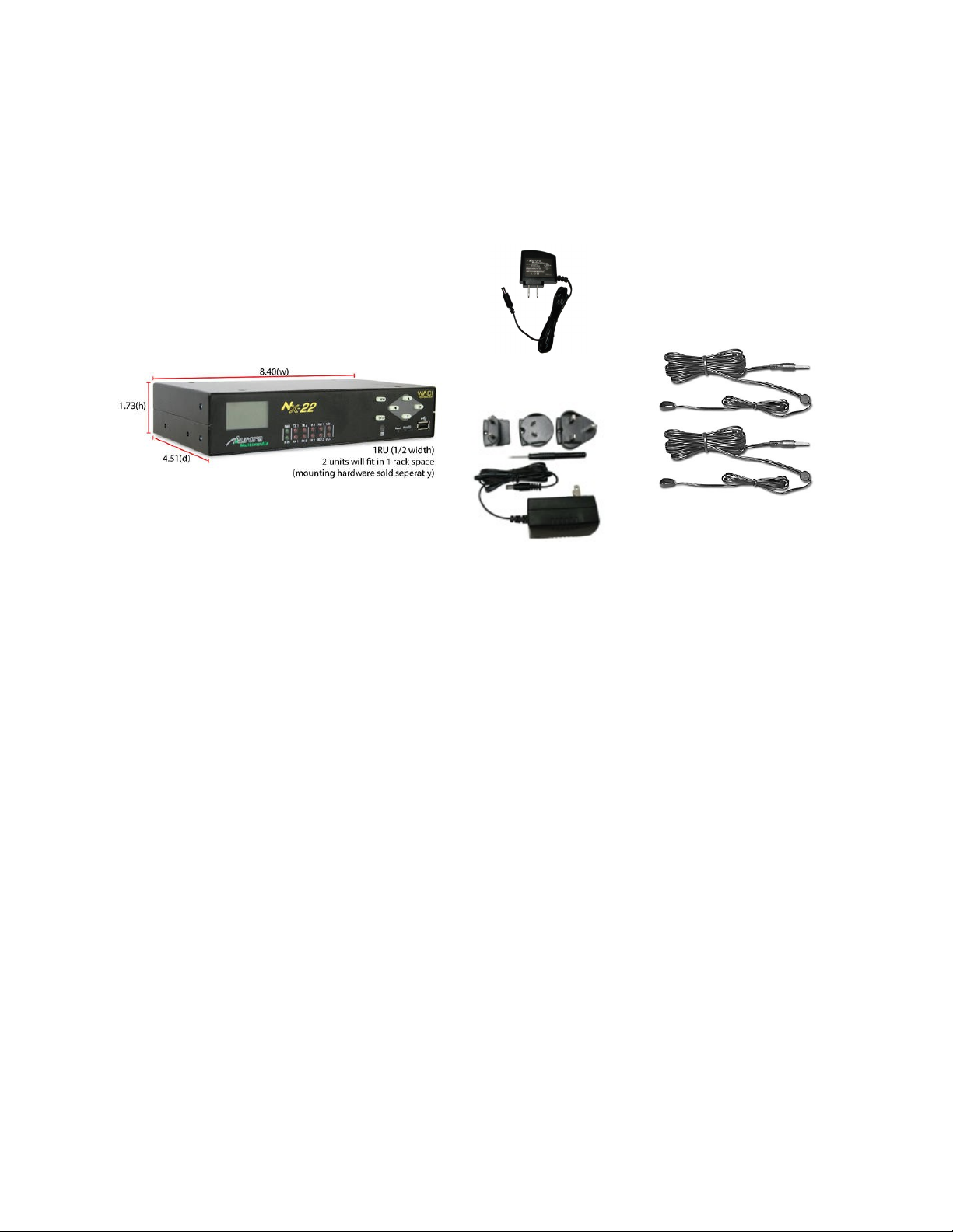
Box Contents for the NX-22
12v 15 Watt Supply
2 IR Port Emitters
International Supply
Kit
NX-22 Device Power Adapters IR Emitters
Page 8

V. Hardware Specifications
General Specifications
NX-22 Notes
Size 1.75” H x 8.4” W x 4.51” D √
Weight 0.8 lbs. √
Power
Adapter
Processor 32-Bit √ 900 MIPS Normal Mode
CoProcessing
12V DC 15watt
√
Cipher √ Supports DES, 3DES,
AES
Implements entire IPsec
packet processing in
hardware – no CPU
burden
True Random Number
Generator (RNG) in
hardware
Robust security is ideal
for most business network
environments – meets
U.S. government and
banking industry
requirements
IR (True Trigger) √ Highly Accurate IR
Capture and reproduction
Memory Total RAM 128M 667DDR2 32 bit wide
Total Flash 256M
Available Flash 220M Available memory may
vary, based on firmware
version.
Display 106 x 56 Pixels Backlit √
Ports LAN Network Adapter (RJ-
45 / Ethernet)
USB OTG (On-The-Go) v2.0 1 400MBits Host or Client
RS-232/422/485 (DB-9) 2 15KV Protection, 115KB
2 10/100MBits Auto MDX
POE on LAN1
Page 9

Infrared Outputs (IR) 2 30KHz – 2MHz
Infrared Input 1 IR input device triggers
Digital Input / Digital Output 2 High Impedance
Relay (SPDT) 2 C-Type (NO, NC, CP)
Audio Unbalance Input 1 20Hz-20Khz
Unbalanced Output 1 20Hz-20Khz
Monitoring 32-Bit Internal Clock/Calendar √
IR Learner √ 30KHz – 2MHz
Expansion Micro SD √ Memory up to 16GB
USB Host 2.0 √ Memory / 802.11b/g/n
Network
Access
Web & FTP √
Specifications subject to change without notice.
Max
RS-232 TX as well
200ma Sink Open Drain
Page 10

Absolute Maximum Ratings for Hardware
Below is a summary of the minimum, maximum, and typical values for the hardware.
These are maximum ratings only. Operation of the device at or above these ratings for extended periods
of time may affect reliability.
Min Typ Max Units Notes
WACI Input Voltage +8 +12 +18 V WACI NX: Min. 15watt supply
Storage Temperature -20 +55 °C
Digital I/O Input 0 12 V Zener protection for higher voltages
Digital I/O Output 0 12 V Can source up to 20mA at 3V and
has open collector mode for higher
voltages.
Relay 0 2 A Max 30V DC
Page 11
Hardware Parts Overview
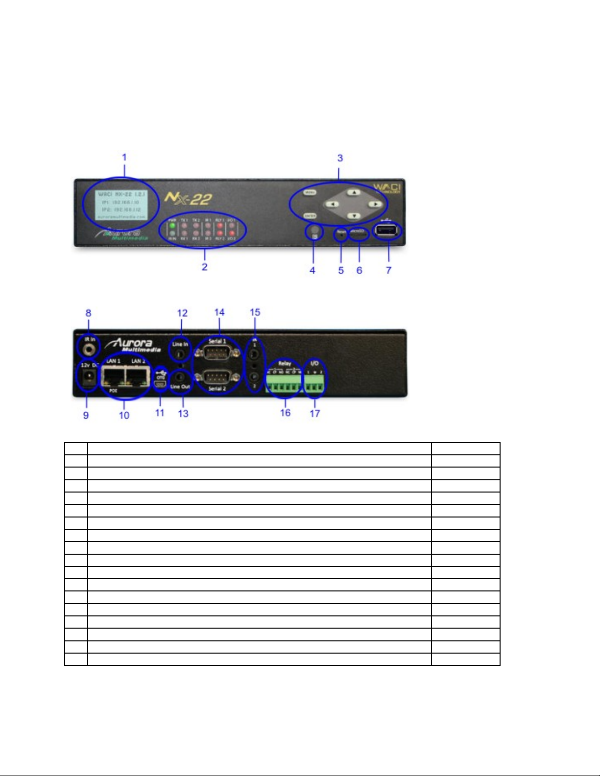
NX-22 Parts Overview
# Short Description More Info
1 Built-in LCD display for setup and diagnostics
2 LED Indicators Power, IR In, Serial, IR, Relays, I/O
3 Six button menu navigation
4 IR Learner Port
5 Reset paperclip button hole
6 Micro SD Memory Expansion
7 USB 2.0 Host
8 IR In Port
9 Power Adapter Port
10 Two 10/100 Auto-MDX LAN Ports (LAN1 has capability POE)
11 USB 2.0 On-The-Go Port
12 Audio Line In
13 Audio Line Out
14 Two RS-232/422/485 Serial Ports
15 IR Ports 1&2
16 Relay Ports 1&2 (Normally Open, Center Pin, Normally Closed)
17 I/O Ports 1&2
Page 12

Detailed Hardware Descriptions
Power Indicator and LCD
A green power indicator is available on both the NX-22. The power indicator is lit whenever power is
applied to the WACI. The LED will stay solid if the system is OK.
Power Adapter
The power adapter is included with the WACI NX. The 15 watts supplied is more then enough to power
the WACI NX as well as certain USB add-on modules
Power Port
The WACI NX is powered using the included Power Adapter. The smaller end of the Power Adapter is
plugged into this port. You should plug the Power Adapter into this port after the network cable has been
attached.
Green Power
The green LED indicates that the WACI is powered and operating.
LCD Display
The 106 x 56 backlit pixel based display helps with the diagnostic and setup of the WACI NX.
Access Boot Menu
Press and hold the any of the 6 buttons for 5 seconds to bring up the Boot Menu while plugging in the
power connector. For more information on the Boot Menu see Boot Menu Reference on page 27. A null
RS-232 cable will be needed for the boot menu to a PC running a terminal program.
Serial Ports
Serial port interfaces are available on both the NX-22.
Serial Ports 1 & 2
The WACI NX has two (2) serial ports that enable RS-232 and RS-422/485 communications, supporting
a wide range of compatible electronics.
The actual connectors on the WACI are DB-9 male ports.
The device or cable you wish to connect to the WACI NX should be a DB-9 female connector.
Page 13

Serial Port Pin-Out Diagram
Pin RS-232 RS-422/485
1 NC RX+
2 RX
3 TX
4 DTR TX5 GND GND
6 DSR
7 RTS TX+
8 CTS
9 NC RX-
LED Indicators for Serial Ports 1 & 2
There are two (2) sets of LEDs, one set for each serial port. Each set consists of two (2) red LEDs that
indicate activity on the pins.
When using RS-232 communications, the two LEDs indicate activity on the TX and RX pins.
When using RS-422/485 communications, the LEDs indicate activity on the corresponding TX+, TX-,
RX+, and RX- pins.
RS-422 Operation:
When using RS-422 operation the RX+ and RX- should have a 120 Ohm resistor across the two pins.
Also, RS-422 operation must be selected in the setup page in order for it to properly work.
RS-485 Operation:
When using the RS-485 operation the RX+ and TX+ should be tied together as well as the RX- and TX-.
There should be a 120 Ohm termination resistor across the two pins. Also, RS-485 operation must be
selected in the setup page in order for it to properly work.
Page 14
Network Interface
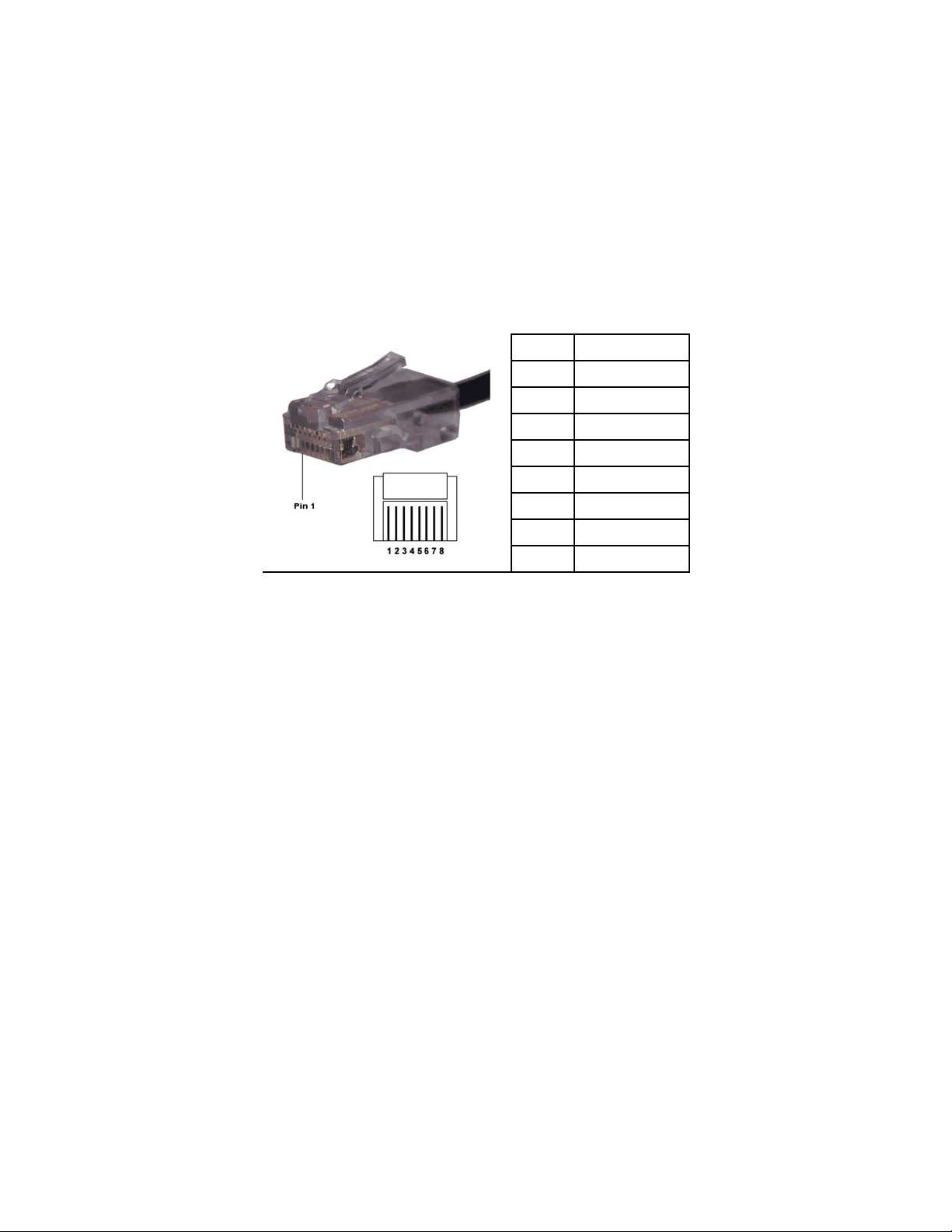
The WACI NX has two 10/100 Auto MDX Ethernet ports. LAN1 is POE (Power Over Ethernet) capable.
The Auto MDX allows the use of null or straight through LAN cables to the ports.
LAN Port
The WACI may be connected to a network using a standard RJ-45 Ethernet cable in this port. Both 10Mb
and 100Mb connections are supported.
Port RJ-45
1 TX+
2 TX3 RX+
4 NC
5 NC
6 RX7 NC
8 NC
LED Indicators
The green LED on the LAN port indicates that a network has been detected.
The yellow LED on the LAN port indicates that data is being transmitted or received through the port.
Relays
The Relays on the NX-22 have two connection types: N.O. = Normally Open and N.C. = Normally
Closed. The “Normal” position is the state of the relay when it is not turned on (not energized). You can
turn the relays on and off using the relay diagnostic page (see Relay Diagnostics, page 45), using an
Event Manager “Relay Action” (see Relay, page 67), or through an RPC method call (see Relay Methods,
page 115).
Relay Ports 1&2
Each port consists of 3 lines: NO (Normally Open), CP (Center Pole), NC (Normally Closed). Connect
the incoming wire to the CP connection, and the outgoing wire to either of the other two ports (NO or
NC). The outgoing port you choose depends on which type of connection you wish to consider “Normal”.
LED Indicators for Relay Ports 1&2
Two red LEDs indicate activity for each Relay Port.
Page 15

Digital I/O 1&2
Each I/O port is capable of being used in one of two different configurations; Digital Input, and Digital
Output. These modes of operation can be configured in the built in setup pages of the WACI NX or via
RPC commands.
Digital Input
The Digital Input is used to read a digital voltage level. It can read 0V (=0) or 3V (=1). Higher voltages
are clamped to 3V. The digital input is perfect for applications requiring simple on/off detection such a
contact switch. By default the port is high impedance for the most flexibility. The setup page can also
allow a pull-up configuration. If the port is left as is then the device connected to the digital input must
supply the high and low voltages.
You can see the state of the Digital Input port using the DIO diagnostic page (see Digital I/O Diagnostics,
page 46) or through an RPC method call (see Digital I/O Methods, page 117).
Digital Output
The Digital Output is used as an open drain and can sink up to 200mA. Setting the port to 0 will leave
sink the input to ground. Setting the port as a 1 will put the port into a high impedance state. The digital
output can be used for triggering relays, LEDs, or any device that will not require more then 200mA of
current.
You can change the state of the Digital Output port using the DIO diagnostic page (see Digital I/O
Diagnostics, page 46) or through an RPC method call (see Digital I/O Methods, page 117).
I/O GROUND Line
To operate properly, the device connected to the input port must be connected to both the GND line of the
connector block as well as one of the two input ports.
LED Indicators for I/O Ports (1&2)
The LEDs indicate that the voltage is on the port. It will be either on (voltage present) or off (no voltage
or less than 1V).
IR Ports
The two (2) IR ports on the NX-22 are used to send infrared commands to devices that can be controlled
using a standard IR remote control. To control a device, connect one of the IR emitters to the IR sensor of
the device to be controlled. In addition the IR port can be used a one way RS-232C (TX only) at rates up
to 115k.
To program the NX-22 to send IR commands, you’ll need to download one of the device appropriate
.WIR files, or use the IR Learner to learn the remote for the device.
Page 16

Use the IR Diagnostics page (see Managing Learned Commands, page 43), an IR Action (see IR Port,
page 67), or an RPC command (see IR_SendCommand ( Port, Group, Command ), page 119) to send IR
commands out the IR ports.
IR Emitters
The IR Emitters are small cables with an IR Emitter at one end and a small audio style plug at the other.
The emitters plug into the IR ports. The emitter end attaches to the device to be controlled. When the
WACI is sending a command to the device through the emitter, the LED on the back of the emitter will
light up.
IR Ports
There are two IR ports on the NX-22. They are located across the Ethernet ports. Plug the IR Emitters
into these ports.
LED Indicators for IR Ports
When an IR command is sent out an IR Port, the LED for that port is lit.
IR Learner
The IR Learner is used to learn the IR codes from a device’s remote control. It can read many different
types of remotes. If it has trouble with your remote, you may need to download from Aurora Multimedia
a .WIR file that is specific to the device.
IR Learner Port
Point your remote at the window on the lower right front of the WACI NX to learn an IR command for
your remote. You’ll need to use the IR diagnostics page to learn the command (see IR Learning, page 41).
IR Learner LED
The LED is lit during the learning process when an IR signal is detected on the IR sensor within the
WACI NX. When the process is first started the LED will glow in and out slowly until a signal is
received. If the remote is too far away it will continue to glow slowly. The correct distance for the
strength of the signal is usually about 6” and will turn the LED solid when the proper distance is
achieved. If the remote is too close then the LED will blink fast.
Page 17

VI. Expansion Hardware
The WACI NX control system has the ability to expand its capabilities using the docking USB 2.0 Host
and USB 2.0 OTG connectors. This expansion bus is capable of high speed connection up to 400Mbps to
pass through small or large amounts of data for additional features like additional ports, Bluetooth Voice
Lift, WIFI, and much more. With the use of a USB Hub even more ports can be added. Always check
with the latest specification of the expansion device to see feature, power and docking requirements.
Specifications are subject to change without notice.
Page 18

VII. Factory Default
Configurations
Default Network Settings for LAN 1 & 2
DHCP Enabled Yes
IP Address From DHCP
Subnet Mask From DHCP
Gateway From DHCP
Host Name WACI
Password admin
Default Serial Settings
Baud rate 9600 baud
Data bits 8
Parity bits None
Stop Bits 1
Signal Level RS232
Handshaking None
Default I/O Settings
I/O Port Digital Input
Page 19

VIII. Quick Start
STEP 1: Powering Up
Locate the power adapter that came with your WACI. Plug the small end into the power supply port
(labeled “Power”) on the lower left side on the back of the WACI, and the large plug into a wall socket or
compatible power supply.
You should observe the following behavior in this order:
• Once power is applied the green Power LED will immediately light as well as the LCD
backlight. It will remain lit while the WACI is plugged in. All other LEDs will be off and the
LCD will have a message “Initializing”.
• The WACI will run through its internal hardware diagnostics.
• After approximately 5-10 seconds (assuming the self-test passes), on the LCD will display
firmware version and current IP addresses for the LAN ports. If a LAN port is set to DHCP it
may take longer as it will try to get an IP address from the DHCP server. Static IP addresses
will allow the WACI NX to boot within 10 sec.
Page 20
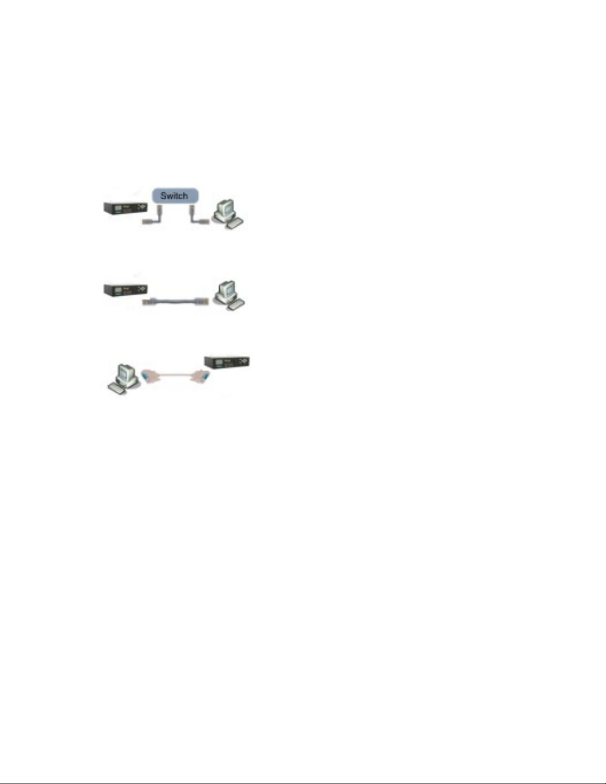
STEP 2: Determining WACI Connection
Decide how you would like to connect to your WACI to configure it:
Connection Type Why use this connection
Connect the WACI NX to a LAN Network and
configure it using a PC on the Network.
Connect the WACI NX directly to a PC using an
Ethernet cable.
Connect the WACI directly to a PC using a
serial data transfer cable (AKA null modem
cable
type?
This is the typical set up for
general WACI NX use.
You do not have a LAN
network, and you need to
access all Admin Web Pages
for configuration.
You do not have a LAN
network, and you only need
to access to the basic setup
configuration found in the
Boot Menu.
or
You need to set up the
manual IP address for a static
LAN network
What do I do next to
connect my WACI
this way?
STEP 3A: Connecting
the NX-22 to a LAN
SKIP to STEP 3B:
Direct Connection if
Static IP is Set
Ignore step 3A.
SKIP to STEP 3C:
Direct Connection with
a Serial Cable
Ignore steps 3A & 3B.
STEP 3A: Connecting the NX-22 to a LAN
The WACI can be configured to use either a static IP, or a dynamically allocated one. By default, the
WACI is set to DHCP for both LAN 1&2. An IP of 0.0.0.0 will be displayed for a LAN port if a DHCP
address is not acquired. (see Default Network Settings, page 18).
If your network is configured to support the default network (IP) settings, you may immediately connect
your hub or router to the WACI using an Ethernet cable with an RJ-45 connector.
If your network is set up to use static IP then you’ll need to change the WACI’s IP address through the
Boot Menu (see Boot Menu Reference, page 27).
Some networks use DHCP to automatically issue IP addresses to machines connected to it. If your
network is setup to use DHCP, then you’ll need to configure the WACI to use DHCP. There are two
Page 21

methods for doing this: 1) press and hold any of the 6 buttons from the front panel for 5 seconds while
plugging in the power for the boot menu 2) go into Setup page of the Admin Web Pages (see Admin Web
Pages, page 31).
Once the WACI is configured correctly for your network, connect a standard Ethernet cable from the
WACI to either a HUB or router.
STEP 3B: Direct Connection if Static IP is Set
If you wish to connect your computer directly to the WACI, you’ll need to use an Ethernet cable (either
null or straight through will work). You’ll also need to set up your computer to use a static IP address.
Set the PC to an IP address in the same range but different from the WACI. A typical configuration is to
manually set the Local Connection on your computer to if the WACI LAN was set to 10.10.10.10:
IP Address 10.10.10.9
Subnet Mask 255.255.255.0
Gateway 10.10.10.1
STEP 3C: Direct Connection with a Serial Cable
You may also configure WACI directly from your computer with a serial connection (see Boot Menu
Reference, page 27).
You’ll need a Null-Modem cable to connect your computer to the WACI. Run a terminal program on
your computer and set the serial communication settings to:
Baud rate 115k baud
Data bits 8
Parity bits None
Stop Bits 1
Flow Control None
Once connected to your computer, press and hold any of the 6 buttons from the front panel for 5 seconds
while inserting the power connector. Configure your network settings as appropriate.
Once the network settings are configured, connect your WACI as described above in step 3A or 3B.
STEP 4: Access the WACI
Once the WACI is physically connected to the network, and the IP address for the appropriate LAN port
is displayed on the front LCD, you may access the WACI through your web browser, FTP client, and
other network clients.
Page 22

The WACI supports the NBNS (NetBIOS Naming Service) for host name resolution. To access the
WACI by its host name, make sure your computer has the appropriate protocols loaded. If you are
running Windows XP, make sure the NWLink NetBIOS protocol is installed. For Windows 9x, the
protocol of interest is NetBEUI. The Apple Macintosh does not ship with NetBIOS support. A third party
driver needs to be installed on the Macintosh computer for it to access the WACI via its host name.
You can use the WACI’s host name or IP address to:
• Upload User-Defined Web pages to:
ftp://[IP Address or Host Name]/wwwpub/
• View User-Defined Web Pages:
http://[IP Address or Host Name]/
• Access Admin Web Pages (Setup, Diagnostics, etc) at:
http://[IP Address or Host Name]/setup/
Some examples are:
http://10.10.10.10/setup/
http://waci/setup/
http://waci/
ftp://user:admin@waci/wwwpub/
STEP 5: Configure WACI Using the Admin Web Pages
Once the WACI is connected to the network, you may configure the device through the admin web pages
at:
http://[IP Address or Host Name]/setup/
Click “Setup“ icon for network and other basic settings. Details describing these options can be found in
the section Admin Web Pages, starting on page 31.
Page 23

IX. Using the WACI
This section summarizes common administrative tasks for running your WACI and refers you to
appropriate sections of this manual for further details.
Testing Hardware
From the Boot Menu (see Boot Menu Reference, page 27), you may:
• Restore Factory Defaults
• Configure IP Settings
• Change Password
• Set Host Name
• Download New Firmware
• Test all the LEDs (see 6: Lamp Test, page 30).
• Check your RAM (see 7: Memory Test).
• Erase the File System
From the Diagnostic web pages, you may check the:
• System Information
• IR Emitter Ports (see, page 39).
• Serial Ports (see Serial Port Diagnostics, page 43).
• Relay Ports (see Relay Diagnostics, page 45).
• DIO Ports (see Digital I/O Diagnostics, page 46).
• System Logs (see Log Files, page 46).
Uploading Firmware Upgrades
Your WACI's firmware may be upgraded by uploading a firmware upgrade file provided by Aurora
Multimedia. Firmware upgrade files will have an extension of .AFW (operating system upgrades) or
.ABT (bootstrap loader upgrades). These files may be uploaded to the WACI after it is set to firmware
upgrade mode. The WACI may be set to firmware upgrade mode through the serial Boot Menu (see 5:
Download New Firmware, page 29) or the Admin Web Pages (see Firmware, page 48).
Page 24

Note: Firmware can be uploaded only one file at a time, and the WACI cannot be used for any other
purpose while in the upgrade mode.
Viewing Server Logs
Logs for the RPC, Web, and FTP servers may be monitored in the Logs section (see Log Files, page 46)
of the Admin Web Pages:
• RPC Server Info (see RPC Server Info, page 47) tells you the version of the RPC server and
the available methods.
• The RPC Server Commands log (see RPC Server Commands, page 47) allows you to see all
HTTP Post calls made to the RPC server. It is typically used for debugging custom
applications and custom web pages.
• The Event Manager Log logs information about the status and execution of Events and
Actions. Errors generated during the execution of the Events and Actions are also written to
this log.
• The log for FTP Server Connections and Commands (see FTP Server Connections &
Commands, page 47) allows you to monitor activity on the WACI's FTP server. It is
typically used to examine user access and determine network needs.
• The log for the Web Server (see Web Server, page 47) allows you to monitor activity on the
WACI's Web server. It is typically used to examine user access, determine network needs,
and debug custom web pages.
Automating Tasks (The Event Manager)
The WACI has built-in, self-monitoring capabilities that will allow you to automate many tasks without
developing web pages or applications. The WACI can be configured to watch for specified states, or
“Events“, such as a time of day or a value on a port. At the time an Event is triggered, the WACI may
then perform some specified tasks, or “Actions”.
The options for these capabilities may be configured through the Event Manager page (see The Event
Manager, page 54), in the Admin Web Pages.
Uploading Custom Web Pages
If you have frequently used tasks or want to facilitate administration of tasks, you may decide to develop
your own custom web pages. Typical reasons for custom web page development:
• Streamlining operations, performing tasks efficiently.
• Custom graphical user interface is required.
Page 25

• Reducing training costs for employees who operate the system controlled by the WACI.
• Easy network access to interfaces is required.
• Facilitation of documentation distribution.
Once your custom web files are created, and your WACI is live on your network, the files may be
uploaded with any standard FTP client to:
ftp://[IP Address or Host Name]/wwwpub/
These custom web pages may be viewed with a web browser at:
http://[IP Address or Host Name]/
For more information about the FTP server and uploading files, see the Files section (page 49) in the
Admin Web Pages documentation.
Using Remote Procedure Calls (RPCs)
In the development of your custom web pages or application, you may wish to get a state from the WACI
or command it to perform some task. The WACI supports many programmable functions through remote
procedure calls (RPCs). For full details, see (see RPC Server Commands, page 47).
Page 26

X. Web Server Features
One of the greatest benefits of the WACI is its ability to serve up custom web pages that you upload to
the device.
The WACI has built-in support for the following web features:
Content Type Notes
Active Server Pages .ASP File Extension
Hyper Text Markup Language .HTML File Extension
Flash Programs .SWF File Extension
Java Script .JS File Extension
Server-Side Includes For example, use <!--#include file=“MyInclude.txt”-->
within your .ASP page or .HTML page.
VB Script Embedded into the .ASP pages
FTP Sever Access using an FTP client
RPC Server Access using HTML post
In addition, the WACI can store virtually any type of file content (see Files, page 49).
Page 27

XI. Boot Menu Reference
Accessing the Boot Menu with a Serial Connection
Connect the Serial 1 Port of the WACI to your computer with an RS-232 Data Transfer Cable (also
known as a Null Modem Cable). Using Hyper Terminal (or similar software), connect to the WACI with
the default Serial Settings: Baud Rate: 115k, Data bits: 8, Parity: None, Stop bits: 1, and Flow control:
None.
Press & hold any of the 6 buttons while inserting the power connector. The WACI Boot Menu will
appear on the terminal screen:
WACI Boot Menu
------------------------------
0 : Display Current Settings
1 : Restore Factory Defaults
2 : Configure IP Settings
3 : Change Password
4 : Set Host Name
5 : Download New Firmware (uses the LAN 1 port)
6 : Lamp Test
7 : Memory Test
8 : Erase File System
9 : OEM Functions
x : Exit menu and boot
Selection:
The boot menu will prompt you through setup and diagnostics.
Details about the options follow in this section.
0: Display Current Settings
Selecting “0” will display the following as an example:
Ethernet Port 1 Settings
MAC address : [00-11-02-02-00-03]
Host Name : [WACINX1]
DHCP Enabled : Yes
Page 28

IP address : [Automatic]
Subnet Mask : [Automatic]
Gateway : [Automatic]
Ethernet Port 2 Settings
MAC address : [00-11-02-01-00-03]
Host Name : [WACINX2]
DHCP Enabled : Yes
IP address : [Automatic]
Subnet Mask : [Automatic]
Gateway : [Automatic]
Password : [admin]
OS Loaded : Yes
OS Filename : nk.bin
<Press Enter>
1: Restore Factory Defaults
This option restores the WACI’s network settings to the factory defaults (see Factory Default
Configurations, page 18).
2: Configure IP Settings
Use to enable DHCP or manually set an IP address, Subnet mask, and Gateway IP address.
Configure which network card (1 or 2)? 1
Enable DHCP (Y/N)?N
Enter new IP address: 192.168.3.165
Enter new Subnet mask: 255.255.0.0
Enter Gateway IP address: 192.168.1.1
Successfully changed IP settings.
<Press Enter>
Configure which network card (1 or 2)? 1
Page 29

Enable DHCP (Y/N)?Y
Successfully changed IP settings.
<Press Enter>
3: Change Password
The maximum length is 8 characters, numbers and letters only. (If you are prompted for a user name as
well as a password, you may use any name or leave it blank.
4: Set Host Name
The maximum length is 16 characters, numbers and letters only. Once set, you will be able to access your
WACI at the URL <http://[Host Name]/>.
5: Download New Firmware
Select “5” to upgrade the OS (*.AFW) or bootstrap loader (*.ABT) file.
The Boot Menu display will first indicate some network initialization, and then the WACI will prompt
you to use a tftp (trivial ftp) client to upload your upgrade file to the WACI at a specific IP address.
At this point, the blue LED will be OFF, and all the Serial LEDs for both ports will be on. You will now
need to upload the OS or boot file using a tfpt client. To use the default Windows tftp client, open a
Command Prompt (or DOS shell) window and execute:
tftp -i [IP Address] put [/File Path/Upgrade File]
Example:
tftp –i 10.10.10.10 put c:\temp\waciplus20.afw
You may only upgrade one file at a time, and you may not do anything else with the WACI in this mode.
During the file transfer, the serial LEDs will blink one at a time, and you will see the status on the boot
menu screen.
The WACI will reset on completion. Continue to use WACI as normal, or press & hold the reset button
for 5 seconds to re-enter boot menu.
Note: The TFTP client is available on Linux, Windows NT, 2000, and XP. Windows 9x, Windows ME,
and the Macintosh O/S’s don’t come with a TFTP client. You’ll need to acquire a third-party client to
upgrade your WACI using these operating systems. Contact Aurora Multimedia for a list of clients that
will work with your O/S.
Page 30

6: Lamp Test
Turns all LEDs on, so you can verify that they are working correctly.
7: Memory Test
Performs a memory scan to validate the integrity of the system RAM.
8: Erase File System
Deletes all files downloaded to the WACI. These are normally the files that have been downloaded using
an FTP client to <ftp://[Host Name]/>.
9: OEM Functions
These are factory options that are configured by the manufacturer, and are not applicable for the end-user.
Page 31
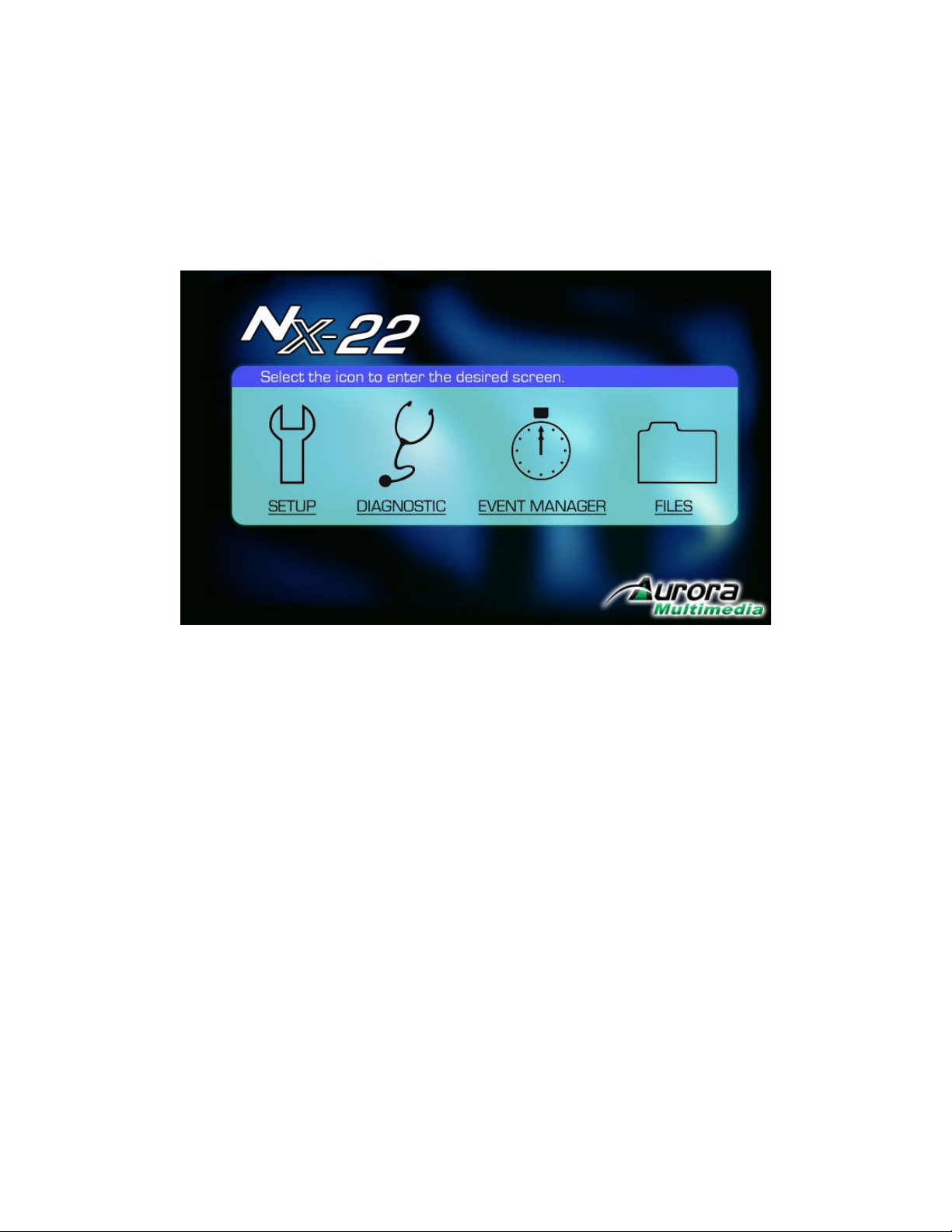
XII. Admin Web Pages
Admin web pages include setup and diagnostic options, and may be accessed at:
http://[IP Address or Host Name]/setup/
From this web page, you may click on:
• SETUP - for firmware version, date/time setting, network settings, and network security
settings.
• DIAGNOSTIC - firmware upgrade instructions, logs, options, and other diagnostic tools for
using and/or monitoring WACI hardware.
• EVENT MANAGER - powerful non-programming tool to automate WACI tasks (see The
Event Manager, page 54).
• FILES - opens an ftp connection to the WACI.
Page 32
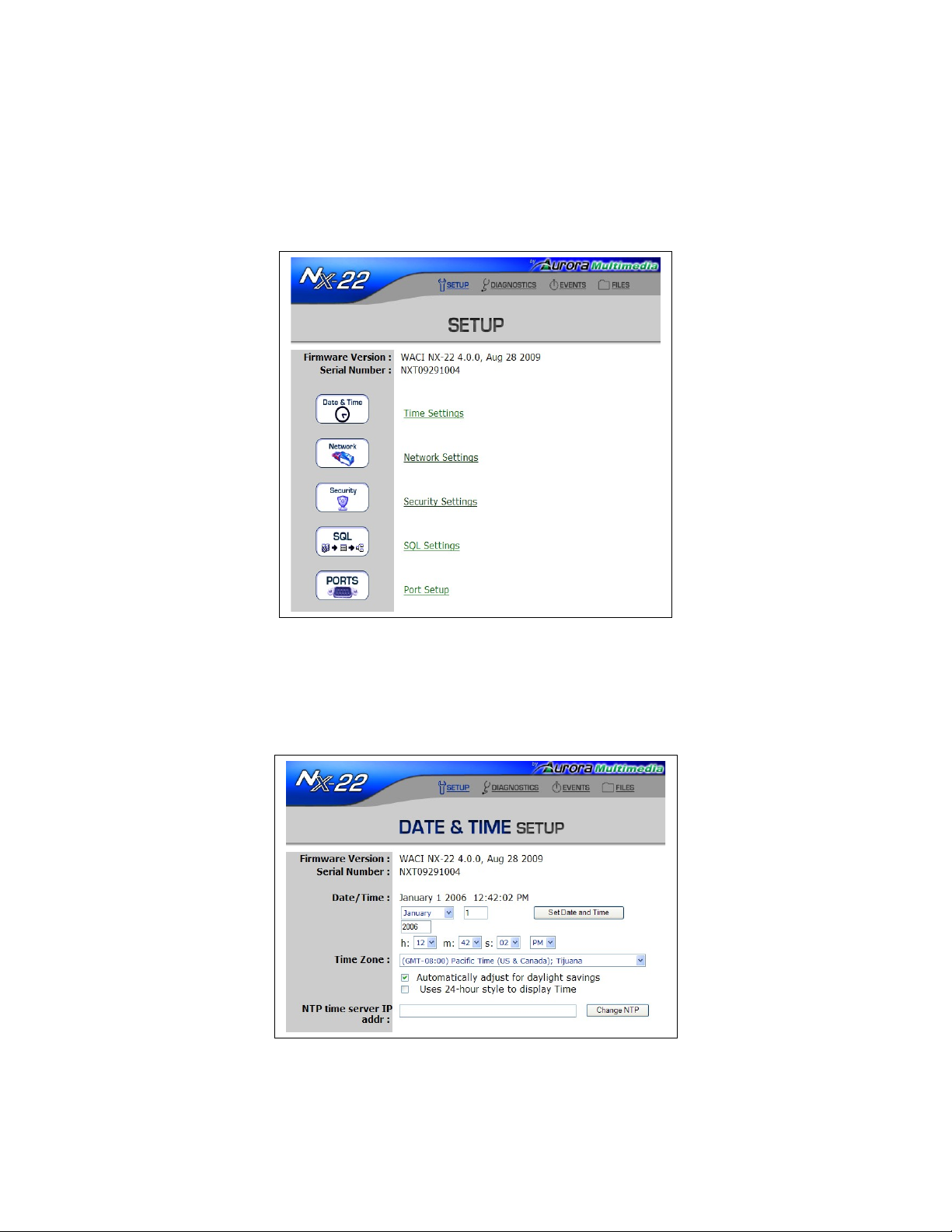
Setup
This web page allows you to set several administrative options. Many of these options are also available
from the Boot Menu.
Firmware Version
The firmware version installed on the WACI is displayed.
Page 33
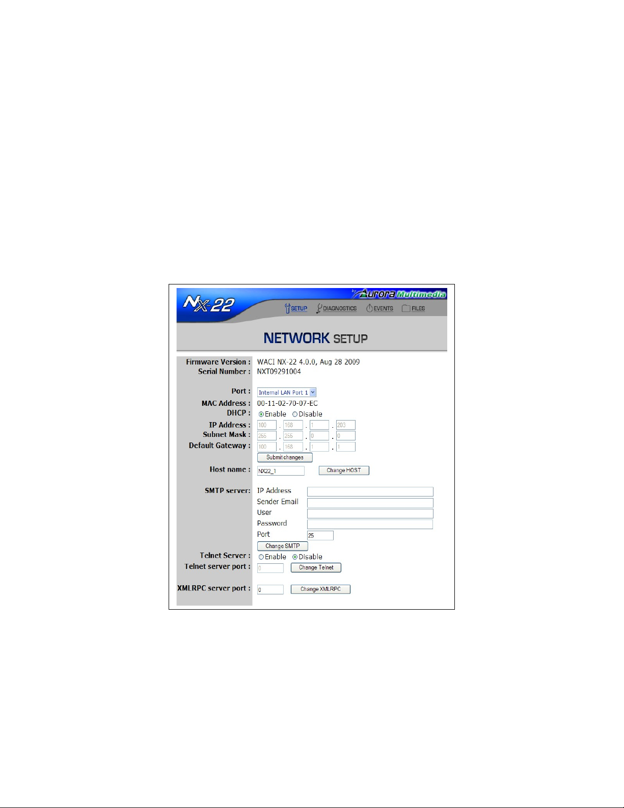
Date / Time
The current date and time is displayed. You may also set the date and time using the pull-down menus.
Once you have made new selections, use the “Set Date and Time” button next to the pull-downs to save
the new date and time.
Time Zone
The time zone setting is used when the WACI communicates with outside computers and servers. Setting
the time zone also allows the WACI to appropriately apply corrections for Daylight Savings Time. You
can set the active time zone by simply choosing one from the list of time zones.
Check the “Automatically adjust for Daylight Savings” check box to have the clock automatically
adjusted when the system enters or leaves Daylight Savings Time.
MAC Address
The WACI Ethernet adapter’s MAC address is displayed to the right of the MAC Address label. You can
use this to validate the IP address assigned in the DHCP server’s address table.
Page 34
Network Settings
If DHCP is enabled for the WACI, the IP Address, Subnet Mask, and Default Gateway are automatically
assigned, and the values will be grey and un-editable.
If the DHCP is disabled, the values for IP Address, Subnet Mask, and Default Gateway will be black and
editable.
Host Name
By setting the host name, your WACI 's web server may be accessed at
http://[Host Name]/
Similarly, the FTP server may be reached at
ftp://[Host Name]/
SMTP Server Address
By setting the SMTP, your WACI 's will be able to send e-mail notifications.
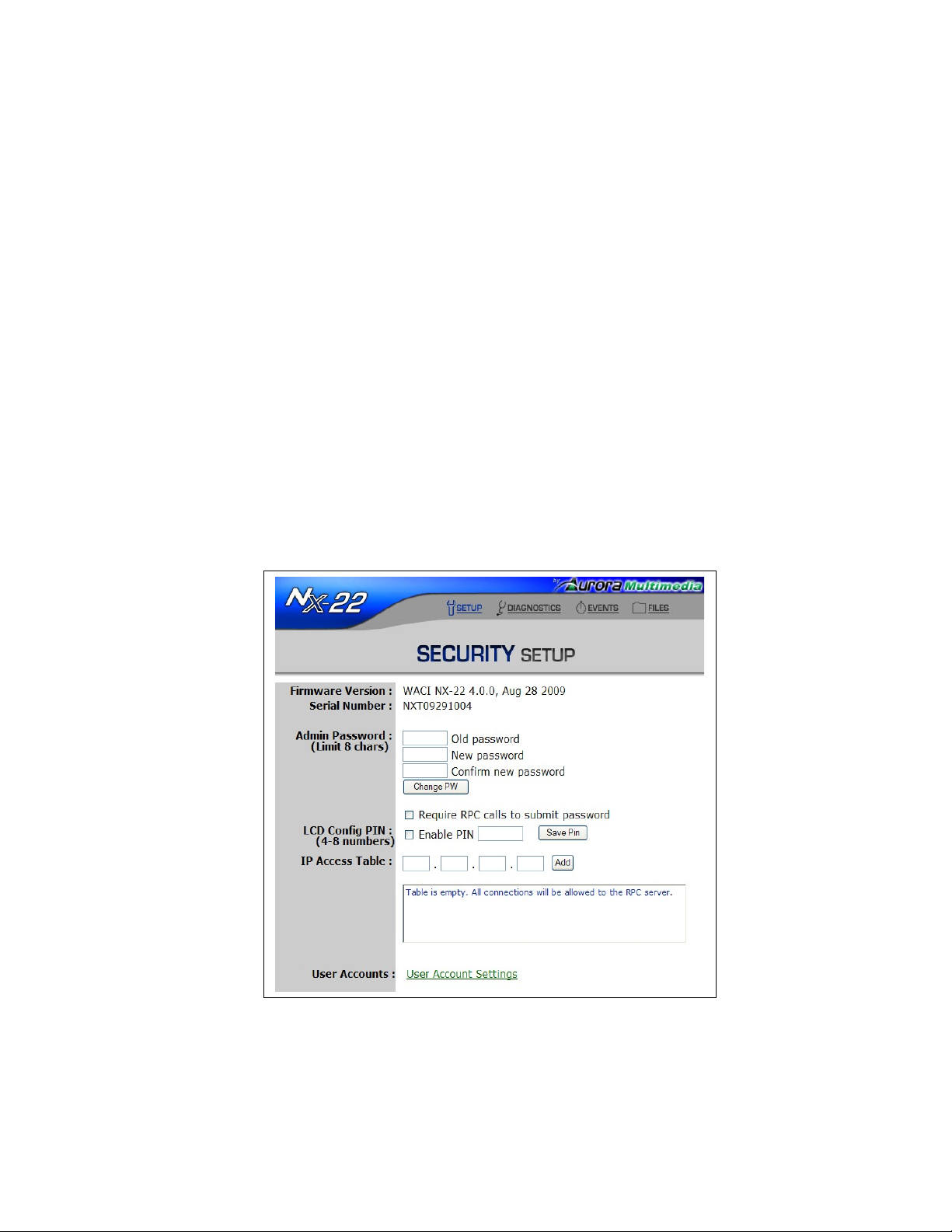
System Password
The password allows you to access the Admin Web Pages and FTP server. No password is required to
access web pages downloaded into the wwwpub directory.
Page 35
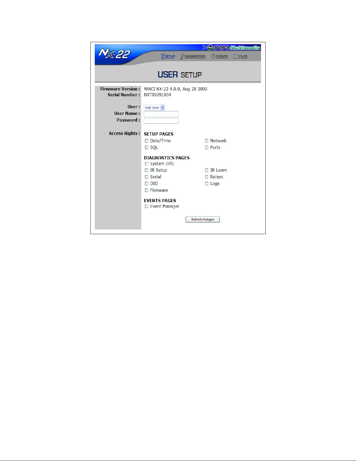
User account settings allows the admin to set up an unlimited amount of accounts for various users and
their required privileges. The URL for user account setup is the IP address of the unit /user (ex.
10.10.10.10/user). Entering this URL address will bring up the user log on access which is limited by the
access granted.
IP Access Table
When specified, your WACI will only accept network requests from computers with these IP addresses.
Page 36
Page 37
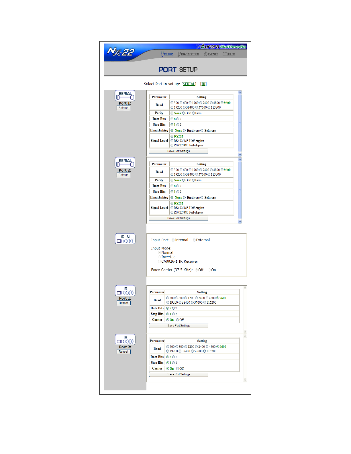
Port Setup
This page allows you to change Serial Port and IR Port settings. NX-22 has 2 Serial ports and 2 IR ports.
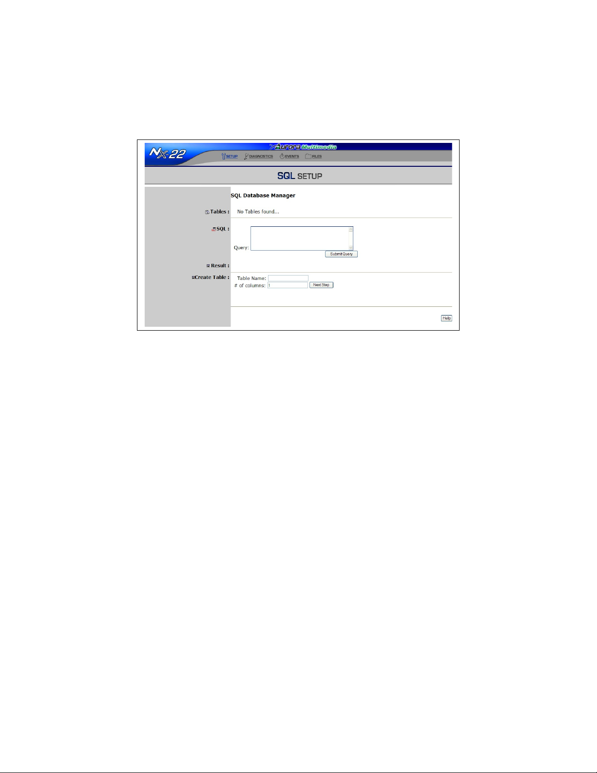
SQL Setup
Using SQL Setup, users are able to create tables, make queries, and store data in a WACI’s database.
Page 38
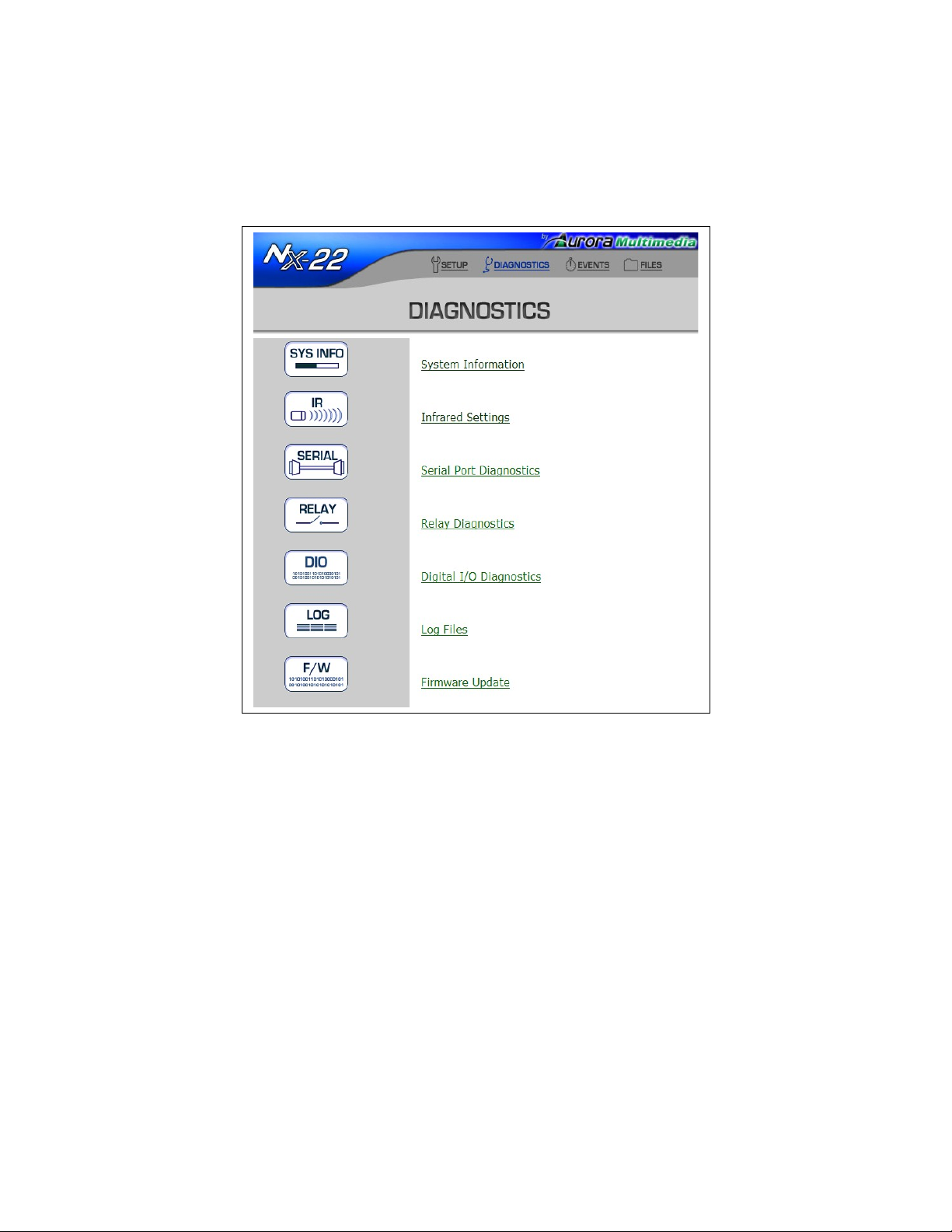
Diagnostics
The Diagnostics web page for the WACI NX-22 reflects its supported diagnostics:
Clicking on either the button or the link on the web page will take you to the available diagnostic tools.
All the diagnostics are presented in this section in the order found on the NX-22 Diagnostics web page.
Page 39
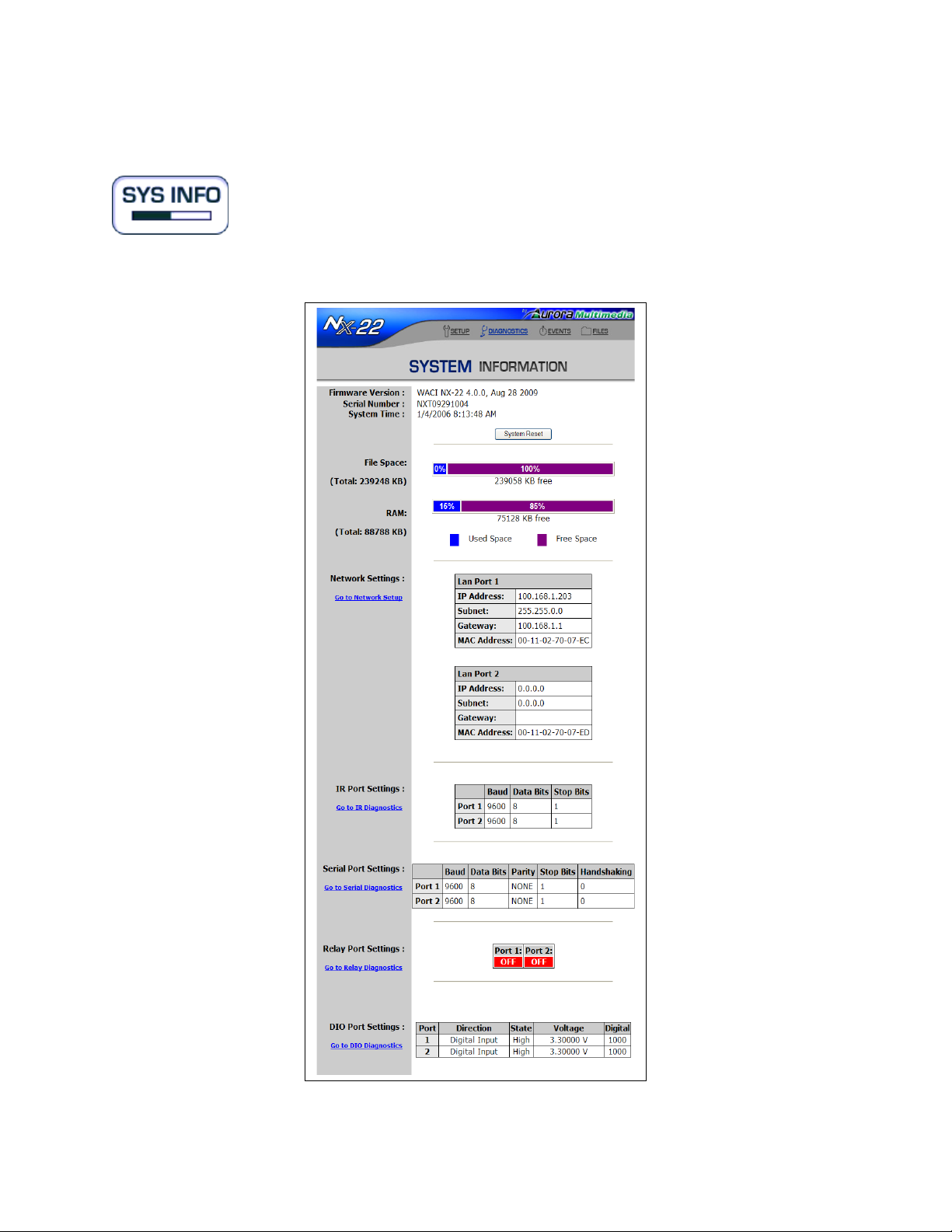
System Information
System information is available for the NX-22. It shows available memory, current network settings, IR
Port, Serial Port, Relay Port, and I/O Port settings.
By clicking “System Reset” button, you can remotely restart WACI. It is useful after making changes to
Page 40
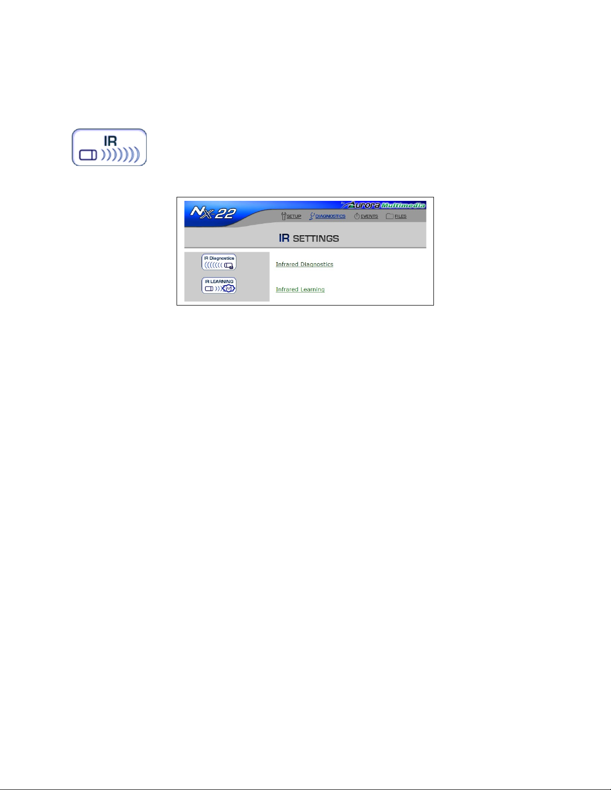
some settings or modifying EventManager file.
IR Settings
When selecting IR Settings a page with 2 choices will appear. One is for IR diagnostics to test already
learned commands or to send RS-232 commands out the IR if used as a serial device. The other selection
is to learn a new remote or to add commands to an existing one.
IR Diagnostics
This page allows you to test various IR commands for a device which has been learned and stored locally
on the WACI. In addition, a user can test an IR port being used as a serial TX only port.
Page 41
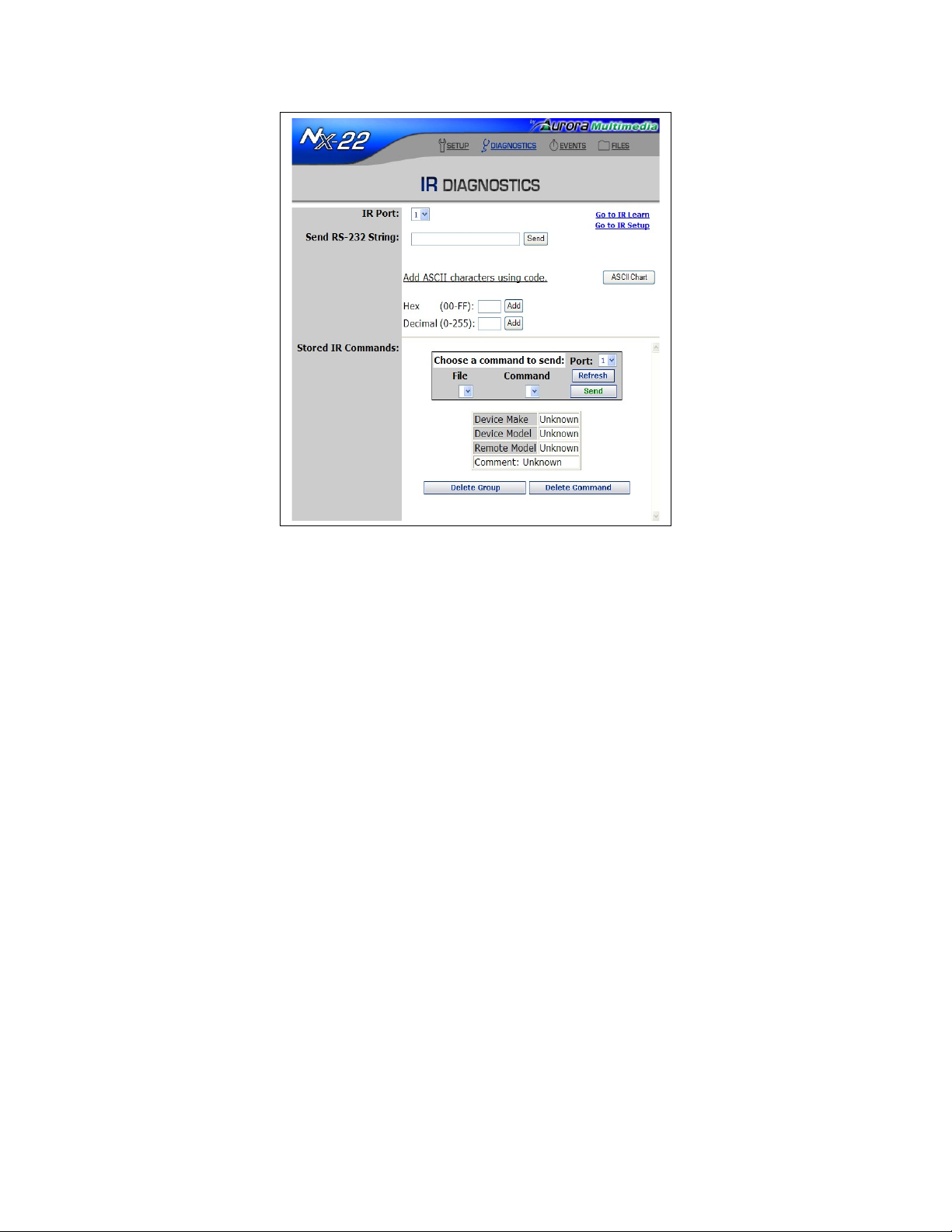
Once a command is selected from the menus of the stored IR commands, you may send the command out
the selected port to the attached IR emitter. When the IR emitter is sending a command, the LED on the
back of the emitter will light up.
You may also refresh the file and command lists by selecting “Refresh Lists”, delete the selected
command by selecting “Delete Command”, or delete the selected group (including all its associated
commands) by selecting “Delete Group”. Depending on your web browser, you may need to scroll down
to view all of these buttons.
IR Learning
This page allows you to “teach” your WACI various IR commands for a device (such as a DVD) using
the remote control for the device. In addition, a complete list of devices and commands may be reviewed,
tested, and/or deleted in the IR Commands section at the bottom of the page.
Page 42
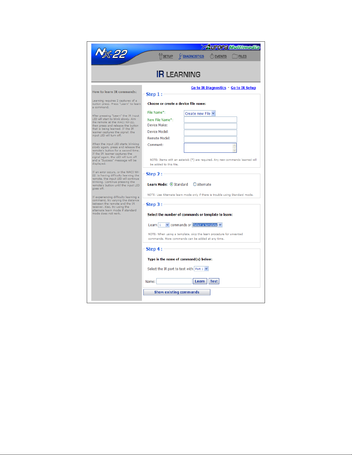
In Step 1, choosing a File Name allows you to “group” all of your IR commands by device. For your
convenience, you may choose a File Name that indicates which device you have chosen to support (such
as “acmeDVD” or “acmeVCR”. You may also enter the Make, Model, Remote Model, and any
Comments about your device (this information is optional). The File Name should contain letters and
numbers only, no spaces.
In Step 2 select the learn mode. Standard is a simple sample of the incoming IR. Try this mode first. If it
does not work then try alternate mode which will do a more intelligent sampling and filtering.
In Step 3, select the number of commands to be learned or from a template of predefined button names.
Templates make learning even quicker. Choose from DVD, Projector, Tuner, DVR, and more.
In Step 4, depending on if you selected template or the amount of learn fields required will determine
Page 43

what is available in this area for learning. If a template was used then fields with predefined names that
can still be edited will appear otherwise you may choose a name for your Command (such as “Play” or
“Eject”). Use letters and numbers only, no spaces should be included in the name. This Command will
be associated with the device / File Name you specified in step 1. There is also a learn x commands
where x is the number of commands to be learned. This allows multiple entries of commands to be
entered before learning which in turn will speed the process.
Finally look for the IR Learner port located on the front of the WACI. Steadily aim your remote's IR
output 6” from the sensors and press the desired remote button you wish the WACI to learn. The IR LED
will glow slowly while the WACI is waiting for an IR signal, and turn solid when it detects a signal. If
the remote is too close the LED will glow fast. The web display will indicate a successfully learned
command or a timeout if nothing was received.
IR Learning Tips
• Hold the remote steady.
• Hold the remote about 6” from learner port.
• Do not confuse the learner port with the emitter or IrDA ports.
• Turn off fluorescent lights.
Managing Learned Commands
You may view all learned commands at the bottom of the page:
Serial Port Diagnostics
The serial port diagnostics are available for the NX-22. From this web page, you may access three
diagnostics for the serial ports.
Serial Send & Receive Histories
First, you may monitor the send and receive histories from either serial port.
Page 44
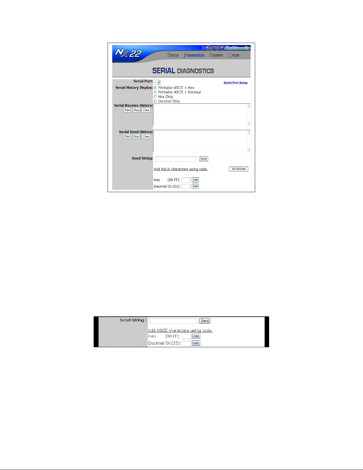
The serial send and receive histories logs the bytes being output or input through the ports. First, select
which port to log (1 or 2), and then specify the display. The bytes passing through the port may be
displayed as printable ASCII characters, hex values, or decimal values.
If you select ASCII characters, you must also choose how you wish to view non-printable characters. The
non-printable characters are denoted by boldface type and “<“ and “>“ parentheses. For example, an
ASCII “space” character, which is non-printable, may be displayed as decimal value <32> or hex value
<20>.
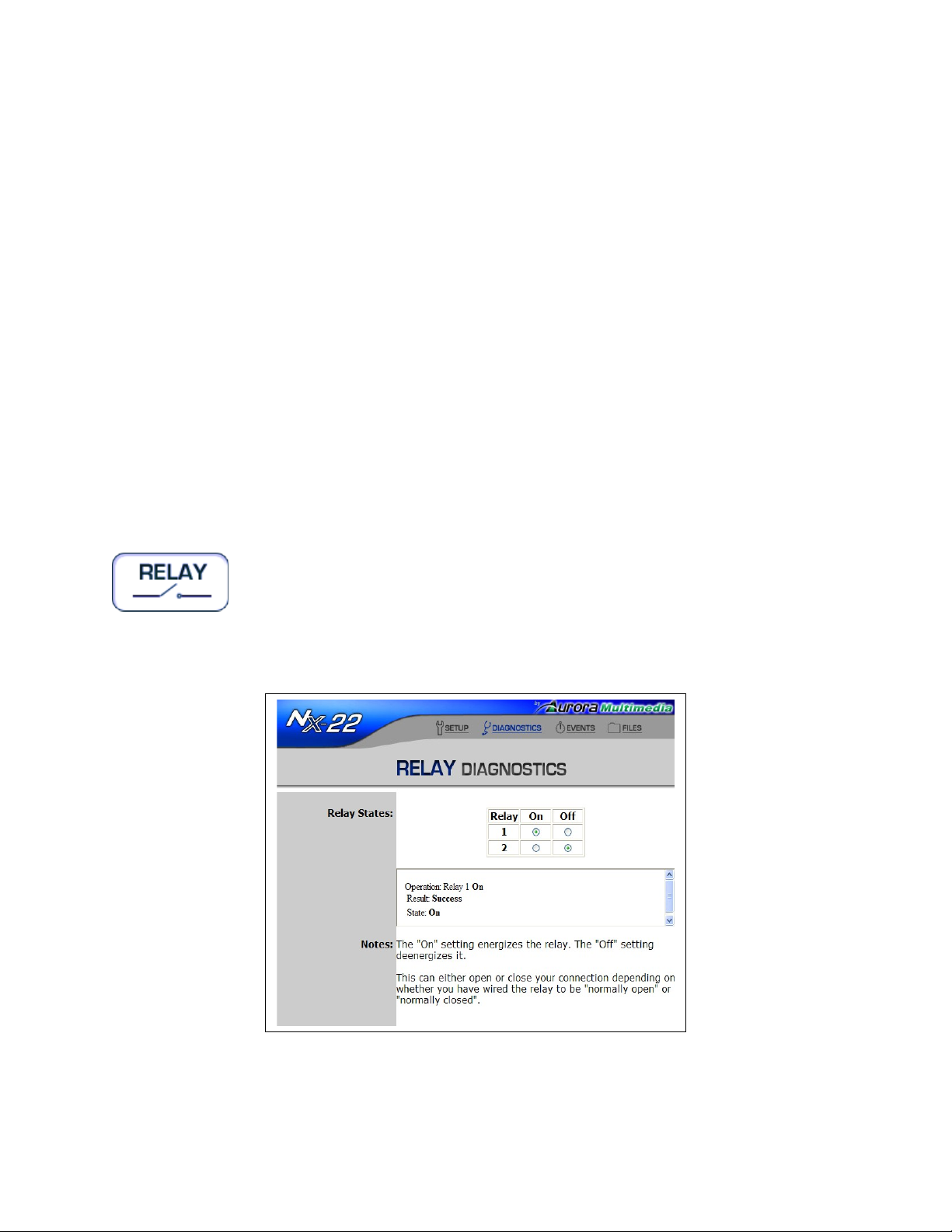
Send String
The second diagnostic allows you to send a byte stream through the port specified at the top of the page.
The byte stream you wish to send must be a URL-encoded send string:
To send a URL-encoded string, follow these three rules for encoding:
1. Enter your byte values as a string of printable ASCII characters and hex values. Spaces and
returns, for example, are non-printable characters and MUST be converted to hex.
2. Any hex value in the send string must be preceded by a “%” symbol.
3. The URL-encoded string does NOT accept decimal values, so if you only know the decimal
value of a byte, you MUST either convert it to a printable ASCII characters or the hex
Page 45
equivalents.
For example, the decimal byte stream “103 111 111 100 32 100 111 103” is equivalent to the hex byte
stream “67 6F 6F 64 20 64 6F 67”. It is also equivalent to the ASCII string “good dog”. However, to
send the string to the serial port, you must use a combination of printable ASCII characters and hex
values only. Therefore, you may send the string as “good%20dog” or “good%20%64%6F%67”, but
not “good%32dog” (where “32” is a decimal value). (You do not need to use quotes in the Send String
text box.)
For your convenience, if you forget URL-encoding rules 2 and 3 above, you may add hex or decimal
values using the hex and decimal fields just below the Send String text box. Adding a hex number to
your Send String with the Add tool simply places the “%” prefix in front of the value you enter, with no
conversions. Adding a decimal number first converts the decimal number to the hex equivalent and
correctly places the “%” prefix in front of it within the send string.
If the Send History log has been started, the send string should appear in that display once the “Send”
button is pressed.
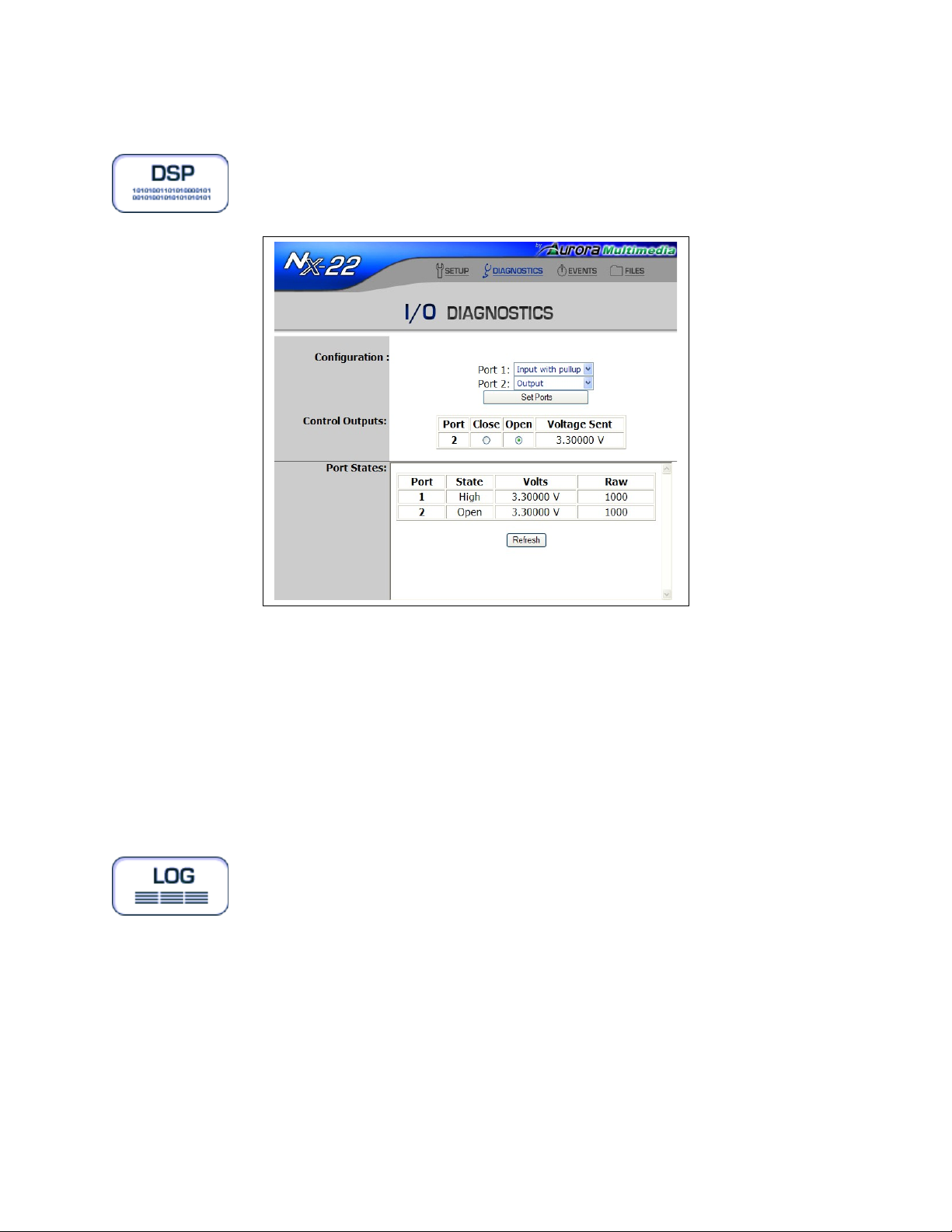
Relay Diagnostics
You may test the relays by clicking the “On” radio button for the port you wish to test. The LED for the
desired relay port should light, indicating the activation of that port.
Page 46
Digital I/O Diagnostics
Each port may be configured and tested as:
• Digital Input (0 to 3V)
• Digital Output (Open Drain sink up to 200mA)
When the state of the port is “High”, the LED light will be on.
Log Files
Log files for the WACI servers are available for the WACI NX-22. An admin may review or clear (reset)
the logs from this page:
Page 47
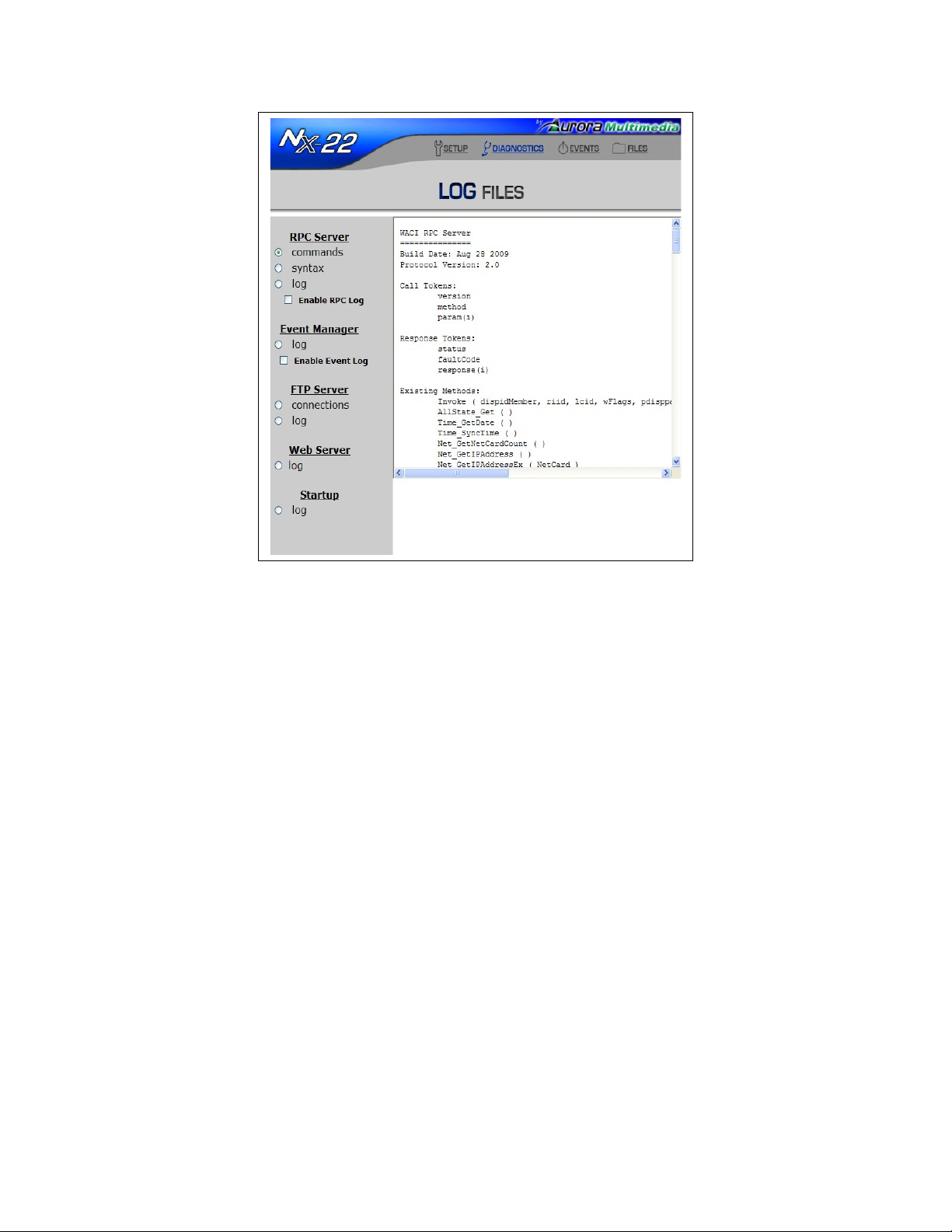
RPC Server Info
Displays the build date and version number of the RPC server. Also displays all tokens and methods
available from the server.
RPC Server Commands
Logs all HTTP Post calls to the server. Active X calls are not logged. Use this log to monitor calls made
to the WACI by your custom web applications. It is quite useful when debugging your application.
Event Manager Log
Logs information about the status and execution of Events and Actions. Errors generated during the
execution of the Events and Actions are also written to this log.
FTP Server Connections & Commands
Logs the FTP activity on the WACI.
Web Server
Logs the HTTP activity on the WACI's web server.
Page 48
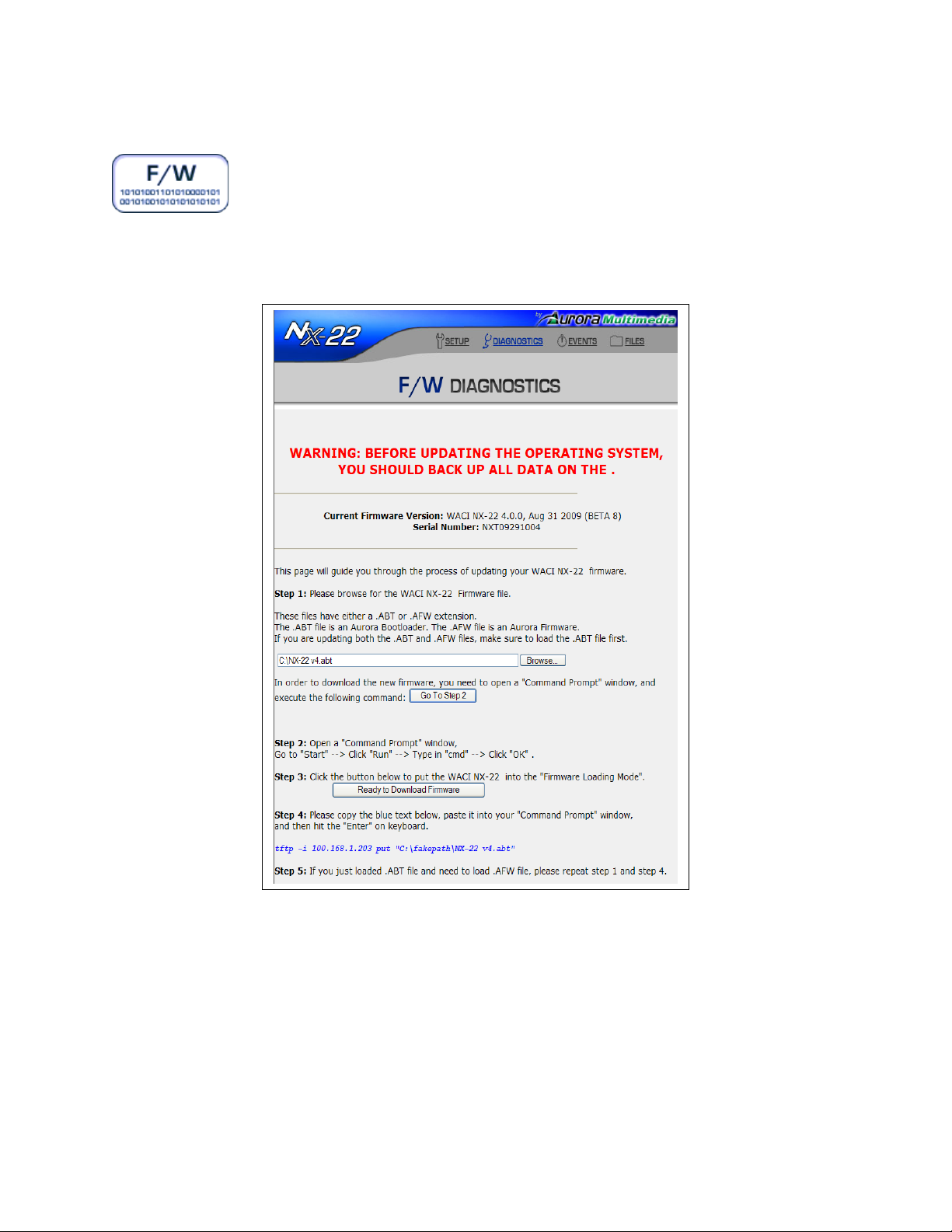
Firmware
The Firmware page, available on the WACI NX-22., will walk you through a WACI firmware update:
First, you will be prompted for the firmware files. Firmware upgrade files will have either the extension
.AFW for operating system upgrades, or .ABT for bootstrap loader upgrades.
Once your upgrade file has been located, the web page will tell you the tftp command line you will need
to execute to upload the file into your WACI. It will look something like:
tftp -i [IP Address] put [Filename with Full Path]
Page 49

If ActiveX is enabled for your web browser, you may also request that the WACI create a batch file
waciload.bat that will execute this command. The batch file will be placed at the root of your local
drive.
To actually upload the file, click the “Ready to Download Firmware“ button. The blue Status LED will
turn OFF, and all the Serial LEDs for both ports will be on. You will now need to upload the OS or boot
file using a tfpt client.
To use the default Windows tftp client, open a Command Line (or DOS Shell) window and execute the
tftp command shown on your web page OR simply execute the batch file. Alternatively, you may doubleclick on the batch file.
While the file is uploading, the serial LEDs will blink one at a time. Once the file is uploaded, the WACI
will reset, and you will be able to access the WACI’s web pages again.
Two important notes:
• You will not be able use the WACI for anything else while it is in the firmware upgrade
mode.
• You may only update one firmware file at a time. If you wish to update both the boot-strap
loader and firmware, you will need to completely upload one first, then repeat the entire
process for the other.
Events (See section: The Event Manager)
Details of the Event Manager are described in the section, The Event Manager (page 54).
Files
Selecting the “Files” link or icon will simply take you to the WACI's ftp server:
ftp://[IP Address or Host Name]/
Typically, selecting this link will display the ftp directory in a browser window, such as Internet Explorer
for Windows XP:
Page 50
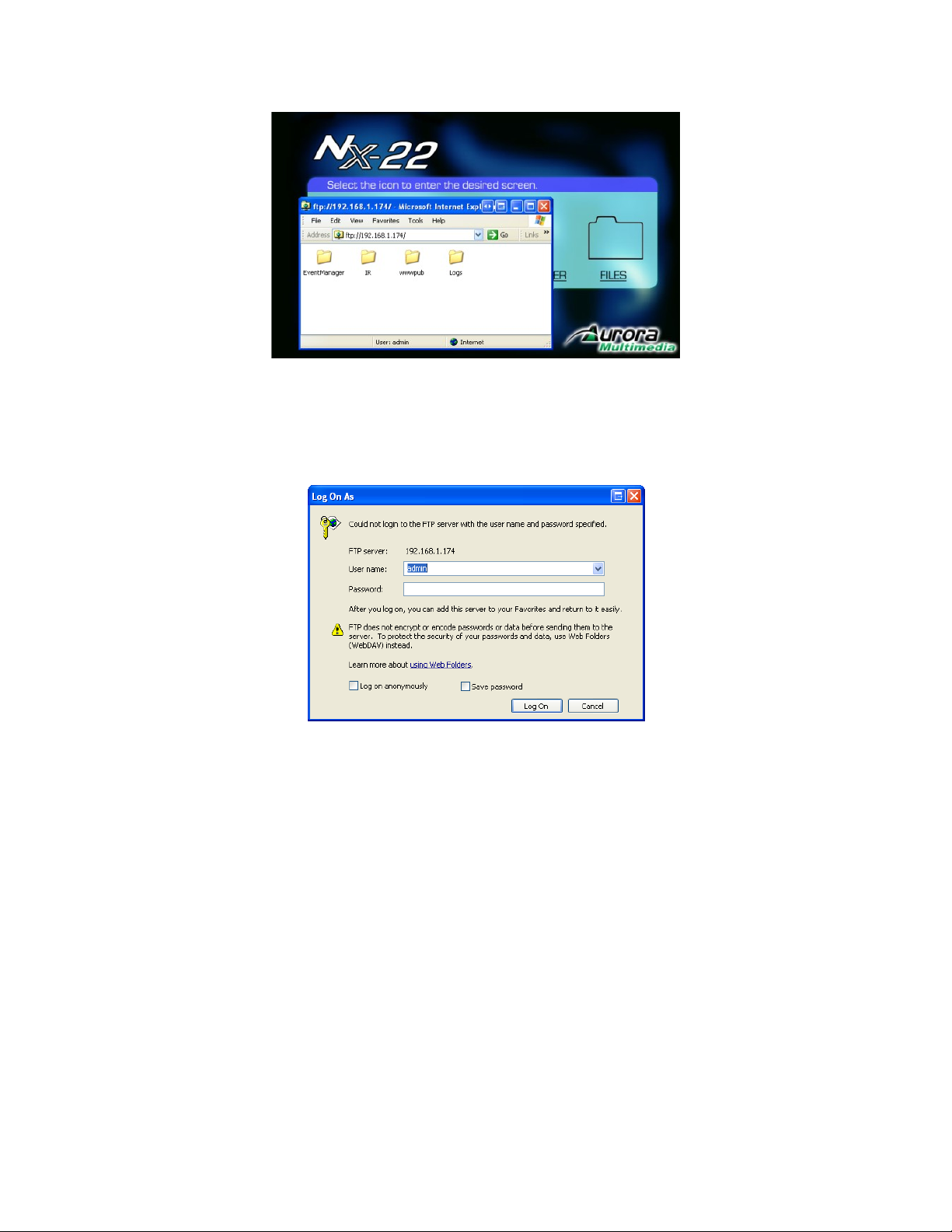
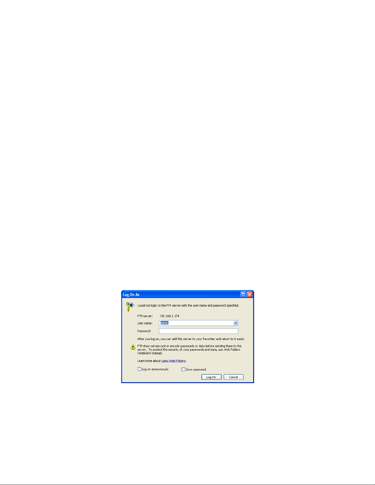
You may be prompted for password, which is the same as the administrative password for the WACI.
Any user name, such as “user”, is valid as long as the password is correct.
NOTE: While this is a convenient way to access the WACI's FTP directories, any standard FTP client
(such WFTP for Windows, Fetch for Macintosh, or “ftp” from a UNIX or DOS command line) may be
used to manage files on the WACI's FTP server.
File Structure
The WACI automatically creates three directories at the root level of its FTP server:
• EventManager - holds data for your custom Events, Actions, and Variables.
• IR - holds IR Learning data for any learned commands.
• wwwpub - holds your custom web pages. Most of your ftp activity will happen in this
directory.
Note that you may not see the EventManager or IR directories until you have started using the Event
Manager and IR Learning features, as explained in the following subsections.
Page 51

EventManager
This directory is created when you create a custom Event, Action, or Variable from the Event Manager
web page (see The Event Manager Web Page, page 55). All Event Manager data is stored in the file
EventManager.wem and backed up in the file EventBackup.wem. Access to these files are
provided for your own convenience, so that you may archive your backups, restore a backup, or create
“frequently-used” sets of Event data that may readily be copied to other WACIs.
Some tips to keep in mind while manipulating the EventManager.wem file:
• This file is read only ONCE, at boot time. The Event Manager may WRITE to the file while
the WACI is operation, but it will not read it again. To reread the file, the WACI must be
reset or powered off and back on.
• Disable the Event Manager before deleting or writing over the EventManager.wem file.
• Reset the WACI (or power off and back on) to read an EventManager.wem file that has
been copied, moved into this directory.
IR
When the WACI learns one or more IR commands for a device (see IR Learning, page 41), all the
commands for that device are saved as a group in one file (you choose a name for this Group/File in Step
1 of the IR learning process). These groups of commands are stored as data files in the IR directory with
the extension .WIR.
For example, if you created an AcmeDVD group of commands and an AcmePlasma group of
commands, you should see the files AcmeDVD.WIR and AcmePlasma.WIR in the IR directory.
Access to these files are provided for your own convenience, so that you may backup your IR commands,
restore a backup, or easily distribute groups of commands to other WACIs. The .WIR files are read by
the WACI as it uses them, so moving or updating a file through the FTP directory does not require that
you restart the WACI. The .WIR file names should contain letters, numbers, and the “_”. No spaces
should be in the name.
wwwpub
In the event that it is convenient to develop custom web pages to monitor and operate your WACI, the
WACI has a built-in web server that will serve up your custom web pages from this directory.
Any custom web pages uploaded to the wwwpub directory may be viewed at:
http://[IP Address or Host Name]/
Allowable File Types
In the EventManager directory, the active Event Manager data file is named EventManager.wem.
This file is read on startup.
Page 52
Command files for IR Learning are stored in the IR directory, and have extension *.WIR.
The WACI's built-in web server supports many Internet standards such as HTML, XML, DHTML, Visual
Basic, Active Server Pages, Java, JavaScript, server-side includes, and Macromedia Flash. All files
supporting these standards (.htm, .html, .gif, .jpg, .asp, .fla, .swf, etc.) may be safely uploaded to the
wwwpub directory.
In addition, files that are supported by client-side applications (such as Adobe Acrobat Reader,
QuickTime, Aladdin Stuffit, etc.) are correctly handled by the WACI's web server. This allows a huge
number of file types such as .pdf, .mov, .wav, .sit, and .zip to be easily accessed from custom web pages.
At this time, the WACI does not support PERL, PHP, or built-in databases.
Uploading Files
You may use any FTP client or web browser to manage the files in the WACI's FTP directories.
For example, using Windows XP, you may drag and drop files from the File Explorer to the FTP
directory in the Internet Explorer window. First open a connection to the FTP server by selecting “Files”
from the Admin Web Page, or by directly navigating to:
ftp://[IP Address or Host Name]/
You may need to specify a username in the URL for direct navigation. Any username, such as “user”,
may be used:
ftp://user@[IP Address or Host Name]/
You will be prompted for password, which is the same as the administrative password for the WACI.
Next, double-click on the directory to which you would like to upload your files.
Page 53
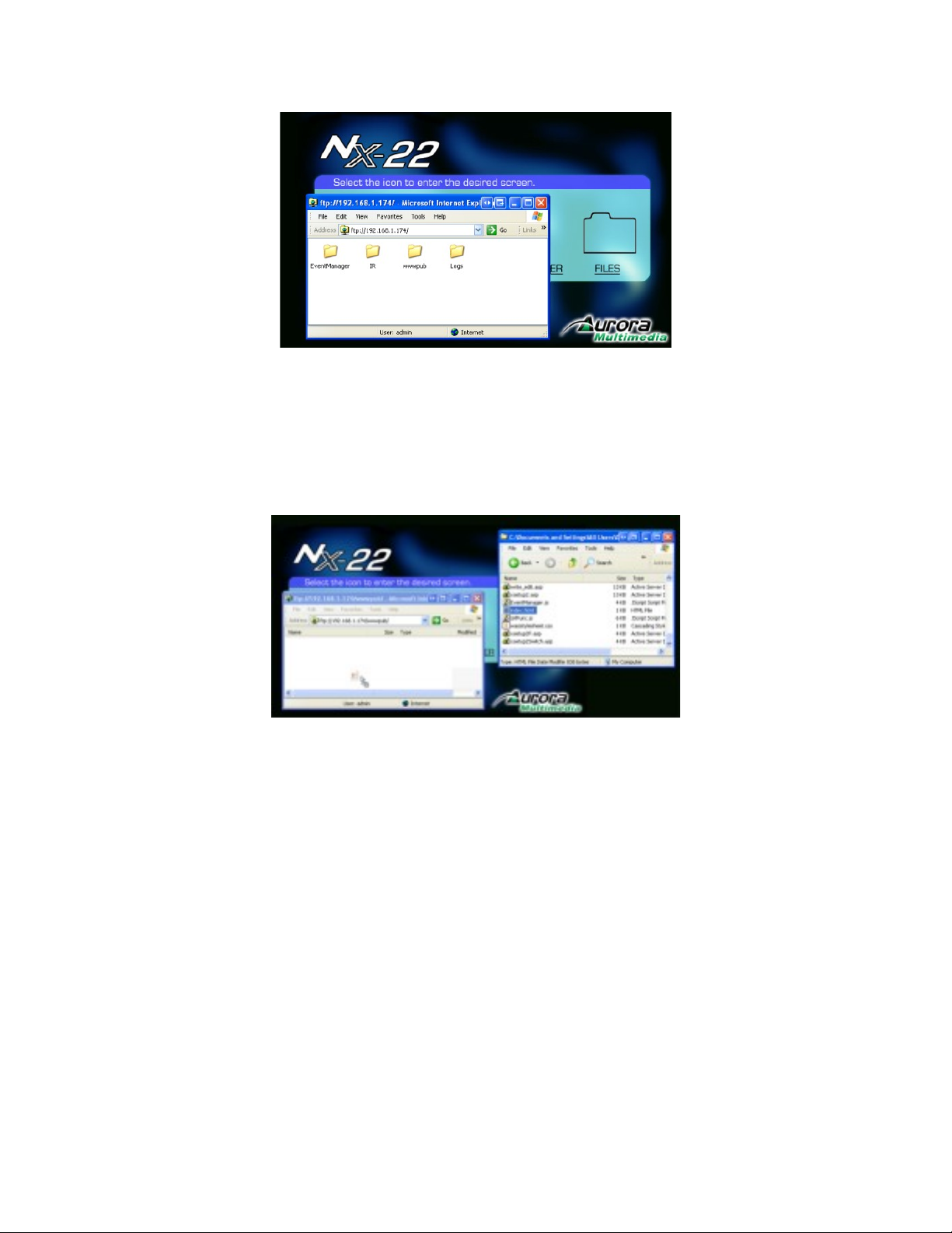
Finally, drag and drop selected files from your File Explorer:
Page 54

XIII. The Event Manager
The Event Manager is a feature of the WACI that allows you to program the WACI to perform operations
autonomously. With the Event Manager, you can associate different hardware or software events with
actions to be performed directly on the WACI. There is then no need to continuously control the WACI
using some client side software. Client side software can then be used to simply check the WACI’s
status.
Overview of Events, Actions, & Variables
In the simplest terms, when certain conditions in hardware or variables are met, the WACI may be
programmed to automatically perform specified tasks. To put this into the context of EVENTS,
ACTIONS, and VARIABLES:
• An EVENT is triggered when conditions in hardware reach a user-defined state, or when a
value of a user-defined VARIABLE matches a user-defined constant or expression.
• Once triggered, the EVENT can fire one or more ACTIONS.
• The conditions in hardware are typically read from one of the ports or the internal clock.
• Under many circumstances, user-defined states and constants can be written as expressions.
Page 55
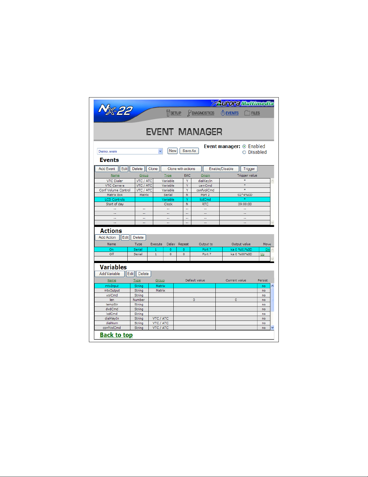
The Event Manager Web Page
The Event Manager page may be accessed by clicking on “Events“ at the top of any page. This page is
organized by Events, Actions, and Variables.
Note that Actions are always associated with its Event. Selecting an Event will highlight the Event and
display all its associated Actions.
Events, Actions, and Variables may be added, edited, and deleted from this page.
Clicking on the heading at the top of the Event or Variable list will sort the respective list. You can use
groups to help organize your Events and Variables.
In addition, you may “Clone” (duplicate) an Event with or without its associated actions.
Disabling the Event Manager renders all triggers inactive without deleting them. This is often useful,
Page 56

sometimes necessary, while:
• Configuring or reconfiguring your WACI with a device.
• Debugging configurations.
• Restoring, copying, or updating an Event Manager file (see EventManager, page 51).
Disable the Event Manager by selecting the Disabled” radio button at the top of the page. Enable the
Event Manager to reactivate all triggers when you are finished with your WACI administration.
Page 57
Events
Creating and Editing Events
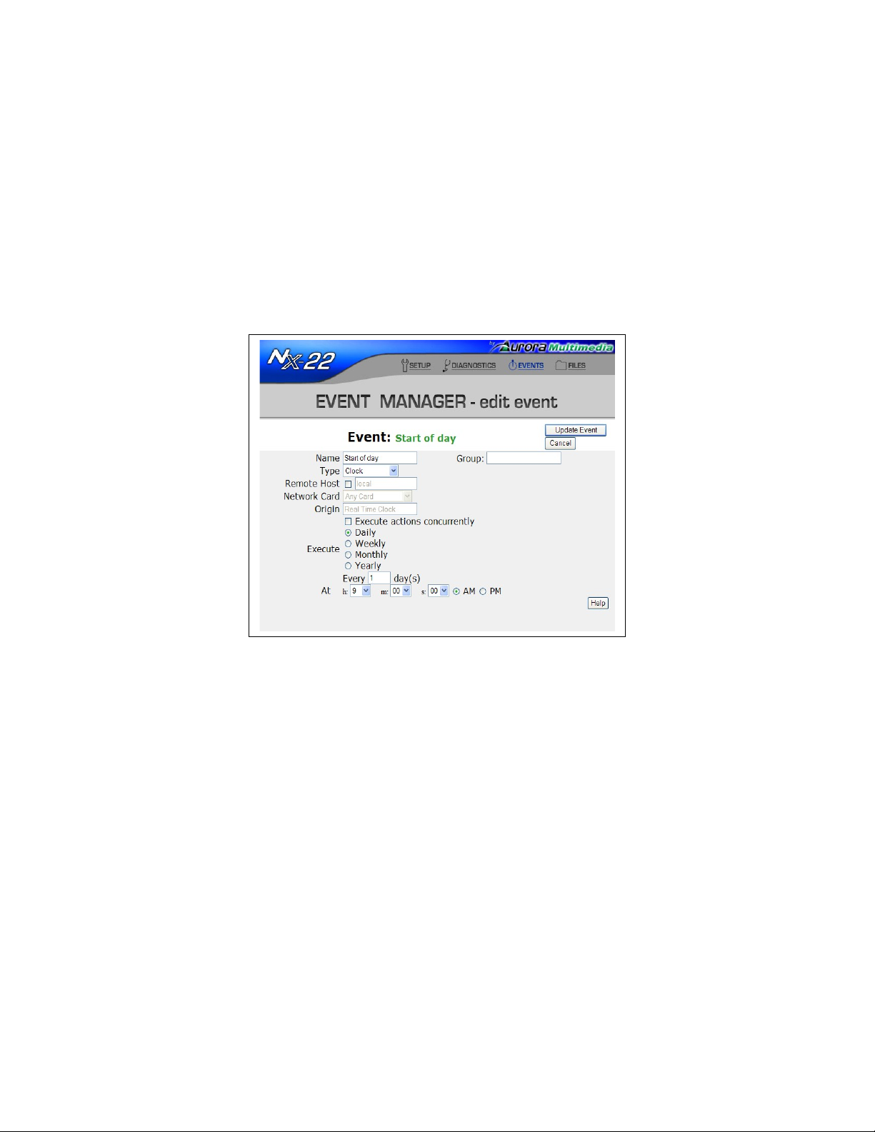
Selecting the “Add event” button from the Event Manager page will create a new Event, while selecting
the “Edit” button above the Event list will allow you to edit whichever Event is highlighted.
You will be prompted for the name of the Event, the type of Event, and any options associated with the
Event, as described in the next two sections.
Types of Events
As mentioned earlier, Events are triggered when a condition is met in the hardware, a Variable matches a
specific value, or an expression evaluates to a non-zero value. The options for triggering an Event depend
on its type. The system recognizes the following types of Events:
Clock
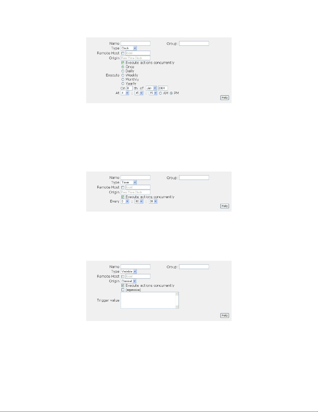
A Clock Event is triggered at a specified time of day on a calendar. Options include the start date and
time, as well as the one-time, daily, weekly, monthly, or yearly recurrence.
Page 58
Timer
The timer operates by counting down from a value specified by hours:minutes:seconds. When the timer
“runs out”, the Timer Event is triggered, and the timer is restarted at the specified value.
While Clock Events allow you to schedule recurring tasks based on fixed, regular calendar periods (daily,
weekly, etc,), Timer Events allow you to schedule recurring tasks based on user-defined time periods.
For example, a Timer Event may be triggered every 27 seconds or 36 hours.
Variable
A Variable Event is triggered when the value of a Variable matches a constant or expression. If the
“(expression)” check box is checked, then the expression defined by “Trigger value” is evaluated
whenever the Variable specified in “Origin” is modified.
Serial
Serial Events are triggered when the INPUT value at a specified port matches a constant or expression. If
the “(expression)” check box is checked, use the “\g” escape character (see Escaping Special
Characters, page 85) to get access to the incoming serial data. Use a “Trigger value” of “*” (see
Wildcard Characters, page 85) to cause any incoming serial data to trigger the Event.
Page 59
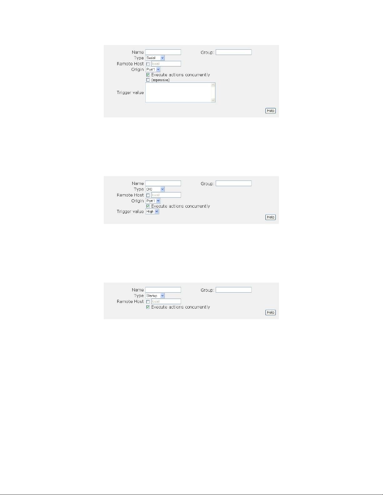
DIO (Digital Input/Output)
A DIO Event is triggered when the INPUT or OUTPUT value at a specified Digital I/O port reaches the
desired state, either low or high. If an expression is defined for a DIO Event, then the expression is
evaluated whenever the state of DIO port changes.
Startup
Startup Events are triggered while the WACI is booting up (typically from reset or power on). These
Events are useful to place the WACI or any devices connected to the WACI into a pre-defined initial
state.
Telnet
The Telnet Event connects via TCP to a Telnet server and monitors any incoming data. The connection to
the Telnet server will be continuously maintained, and if the connection is dropped, the Event will
attempt to reconnect once per minute. The WACI also supports incoming Telnet connections, and will
accept those connections if an Event exists having an “Origin” that matches the incoming connection.
Fill the “Origin” field with the IP address or machine name of the Telnet server. Use the “Trigger Value”
to define the value to match to cause the Event to be executed. The “Trigger value” used by a Telnet
Event is similar in format to a Serial Event’s.
Page 60
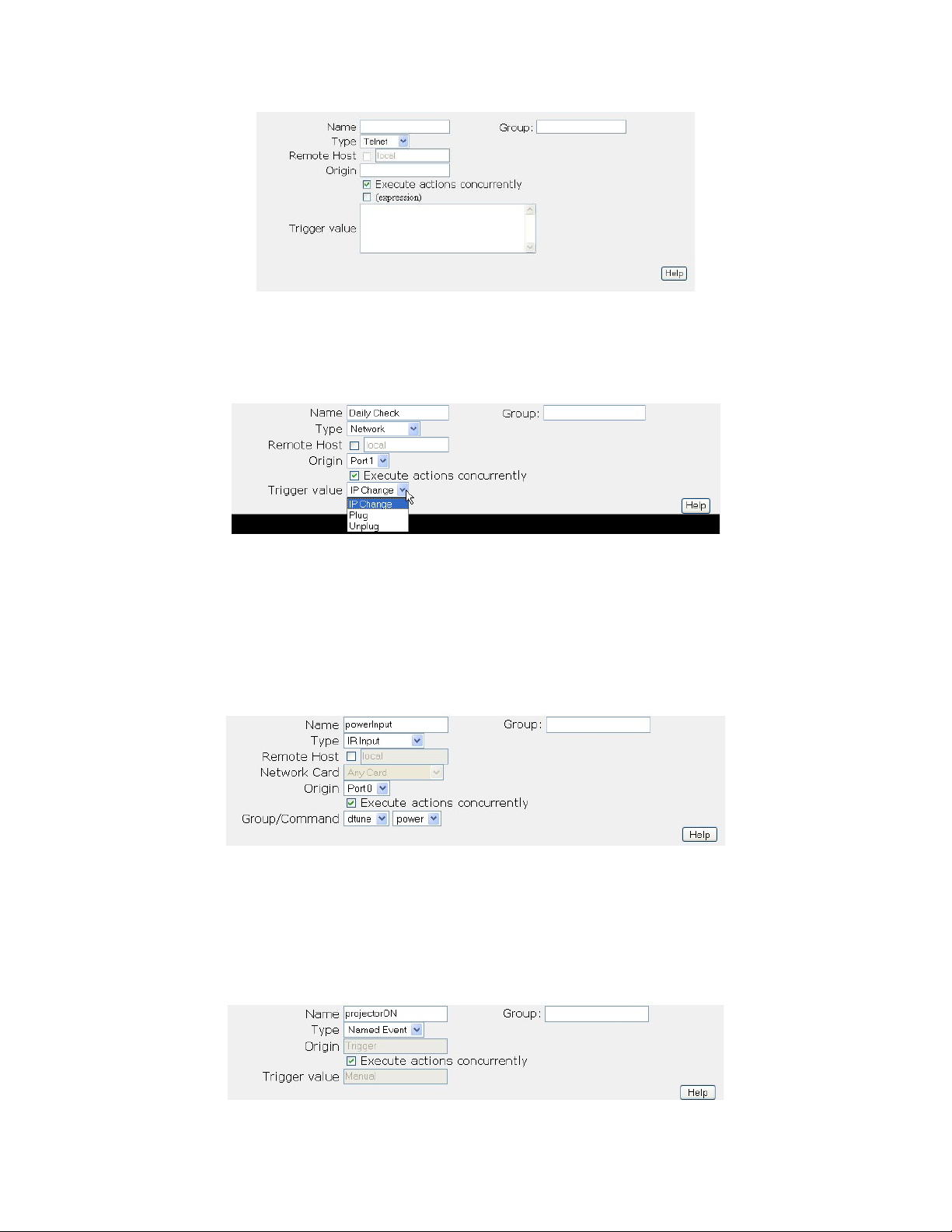
Network
The Network Event allows you to trigger when the status of one of the Ethernet Ports changes.
IR Input
The IR Input Event allows you to trigger events based on the IR command received from
the external device connected to WACI using IR In port.
Named Event
The Named Event is the Event that can be only triggered manually.
Page 61

Other Event Options
Group Name
To help organize Events into meaningful groups, a Group field is available. Enter any text into this field.
On the main Event Manager page, you can click on the Group label at the top of the Event list’s Group
column to sort the Events by their Group name.
Execute Actions Concurrently
When the “Execute actions concurrently” check box is CHECKED, all the actions associated with the
Event will be executed concurrently at the time the Event is triggered. Use the Action’s “Delay By” value
to offset the start time of a particular Action.
If this check box is UNCHECKED when the Event is triggered, its actions will be executed sequentially,
one at a time, and in the order displayed on the Event Manager web page. The next Action in the list will
not start until the previous Action has fully completed. Setting an Action to execute infinitely will prevent
any Actions listed afterward from running.
Expression
When the “(expression)” check box is CHECKED, the value specified in the “Trigger value” text box will
be parsed as an expression (page 73). When the expression evaluates to a value not equal to 0, then the
Event triggers and executes its Actions.
If the “(expression)” check box is UNCHECKED, the value specified in the “Trigger value” text box will
be considered a constant.
Trigger Value
This text box is used for Events that are triggered by matches on a user-defined constant or expression.
Like Variables, constants may be strings, numbers, schedules, or ranges.
To trigger an Event using an expression, the result of the expression must be resolved to an integer value
not equal to 0. An expression that results in a string value will not trigger unless the string can be
converted to an integer value that is not equal to 0, e.g. “Hello” won’t trigger, but “3” will.
Remote Events
When connecting two or more WACIs up to a system, one of the WACIs can be used as a controlling
WACI. The controlling WACI monitors the state of the remote WACI, and triggers the remote Event on a
change in the remote WACI’s hardware or a change in one of the remote WACI’s Variables. To make a
remote Event, check the “Remote” check box and specify the host name or IP address of the remote
WACI. To make setup easier, make sure both the controlling and remote WACIs are connected to the
network and powered up.
Page 62

When a remote Event is created, a copy of the Event is place on the remote WACI. This remote copy
cannot be changed, but can be seen if you open the Event Manager web page on the remote WACI. The
copy will have the IP address of the local WACI appended to the end of the Event’s name.
Page 63
Actions
Creating and Editing Actions
Actions are the tasks performed when an Event is triggered, so they are always associated and displayed
with their Events.
Actions may be created from the main Event Manager web page by first selecting an Event, highlighting
it, and then selecting the “Add action” button.
Similarly, to edit an Action, first select an Event, and then select the associated Action. When the desired
Event and Action are both highlighted, the “Edit” button above the list of Actions may be selected. From
the “edit action” page, you will have several options based on the type of Action.
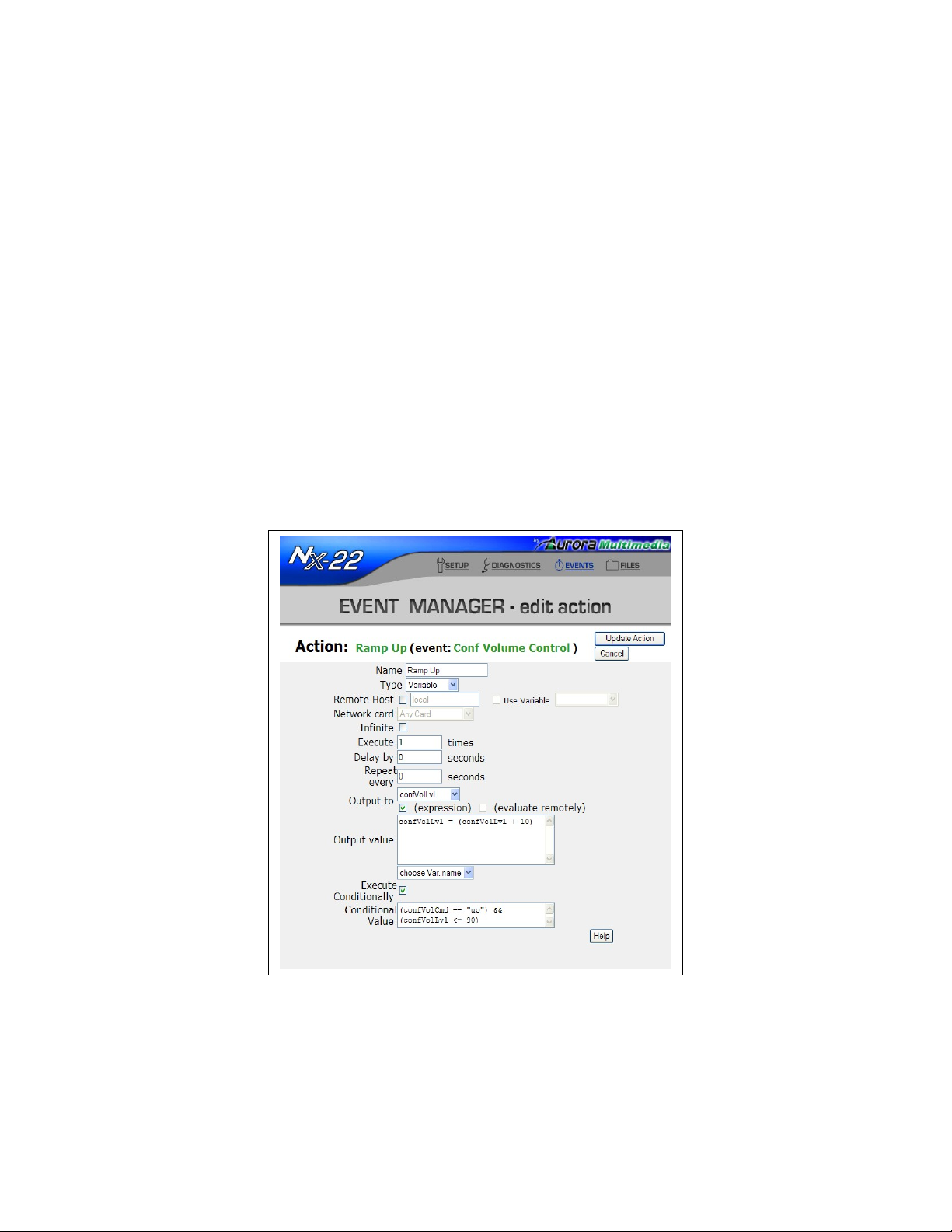
Actions also have the ability to be triggered conditionally. If the Execute Conditionally box is checked
the condition entered into the field must be true in order for the action to trigger. Think of this ability as a
If…Then...Else capability.
Page 64
Types of Actions
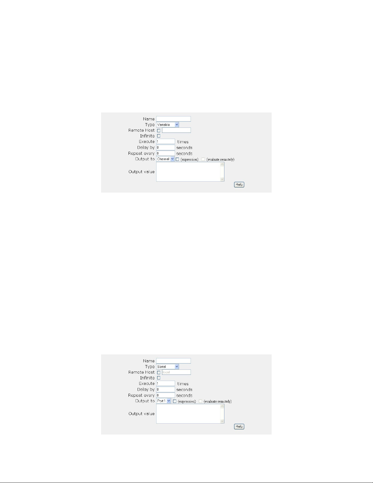
Variable
A Variable Action allows you to change the value of a Variable (see Variables, page 71) once an Event is
triggered. Options that must be defined for the Variable Action are the Output Variable and the Output
Value.
The “Output Value” may be set to a constant, such as Hello or 5, or an expression, such as
Counter+1. If the “(expression)” check box is UNCHECKED, the value will be interpreted as a
constant of the same type as the Variable.
If the “(expression)” check box is CHECKED, the “Output to” Variable will be assigned the value
calculated for the expression in the “Output Value” text box. The Variable’s type is not changed by the
assignment. Prior to assigning the result of the expression to the Variable, the result is converted to the
Variable’s type, e.g. a number. The interpretation and calculation of expressions are detailed in the
Expressions section.
Serial
A Serial Action allows you to send a string to a specified port. If the “(expression)” check box is
UNCHECKED, the value in the “Output Value” text box will be sent as a string to the specified port.
If the “(expression)” check box is CHECKED, the expression in the “Output Value” text box will first be
interpreted as described in the Expressions section and the resulting string value will then be sent to the
specified port. If the result of the expression is a number, then it will be converted to a string prior to
being sent out the serial port.
Page 65
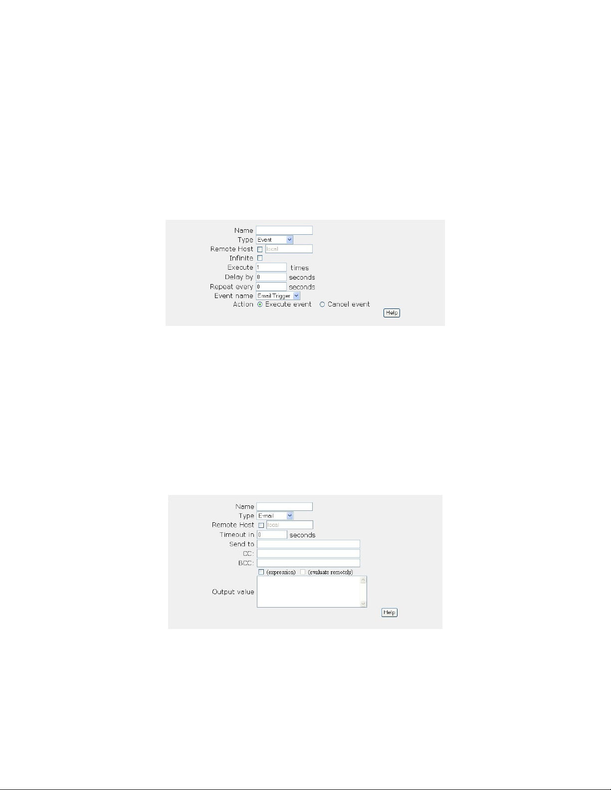
Event
An Event can fire Actions that trigger or cancel other Events. An Event Action allows you to specify the
Events to “execute” or “cancel”. Executing an Event means that if the Action’s Event is not already
running at the time the Event Action is called, the Action’s Event will then be triggered, and any
associated Actions will be fired. Canceling an Event will stop the running of any Actions associated with
the Event, then un-trigger the Event.
NOTE: When an Event is triggered, it remains triggered until all Actions have been completed. Once the
Actions are complete, the Event’s “triggered” flag is reset.
E-Mail
The E-mail Action sends an e-mail to a set of recipients. There are fields for the To, Cc, and Bcc
addresses, as well as, a field for the message body. The message body can be either a simple text string,
or a complex expression. The subject line of the e-mail is created from the name of the Action.
There are no repeat values specified for E-Mail Actions. The Action will execute only once per Event
trigger.
Use the “Timeout in” value to have the Action abort, if it doesn’t complete before the time-out period
expires.
HTTP Post
An HTTP Post Action can be used to post data to a web server. The format of the posted data is
dependent on the capabilities of the server receiving the post. The data returned by the server is discarded.
HTTP Post Actions are useful for commanding a server to perform a particular operation.
Page 66
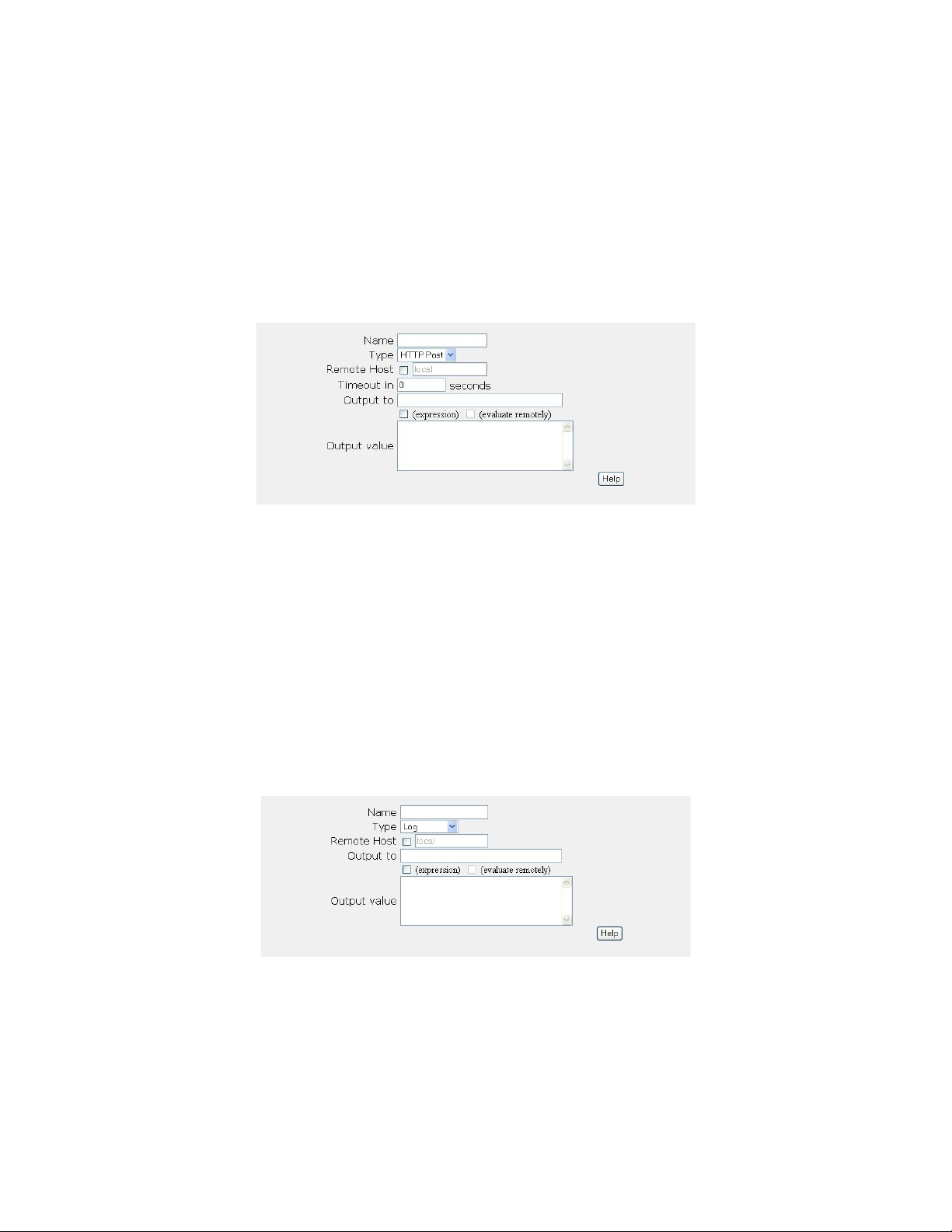
There are no repeat values for HTTP Post Actions. The Action will execute only once each time the
owning Event is triggered.
Use the “Timeout in” value to have the Action abort, if it doesn’t complete before the time-out period
expires.
The HTTP Post Action can be used to make RPC calls to other WACIs. Set the “Output to” field to the
/rpc directory of the other WACI, e.g. 192.168.0.120/rpc. The “Output value” should be the RPC
call (see Syntax for HTTP Post).
Log
Use the Log Action to write information about the status of the system, or about a specific Event to a text
log file. Specify the name of the log file using the “Output to” field. The content of the “Output value”
field is written to the log file. The “Output value” can contain either an expression or a simple piece of
text.
Log files are created in a /logs directory on the WACI. To get access to the file, you can use FTP, or
the Log_ReadFile RPC function.
There are no repeat values for Log Actions. The Action will execute only once each time the owning
Event is triggered.
Telnet
A Telnet Action can be used to send data to a Telnet enabled network server device. The format of the
telnet data is dependent on the capabilities of the server receiving the data. The data returned by the server
can be obtained if a Telnet Event is created for the same server. A Telnet Action will create a temporary
connection to a Telnet server, if no Telnet Event to the same server already exists.
Page 67
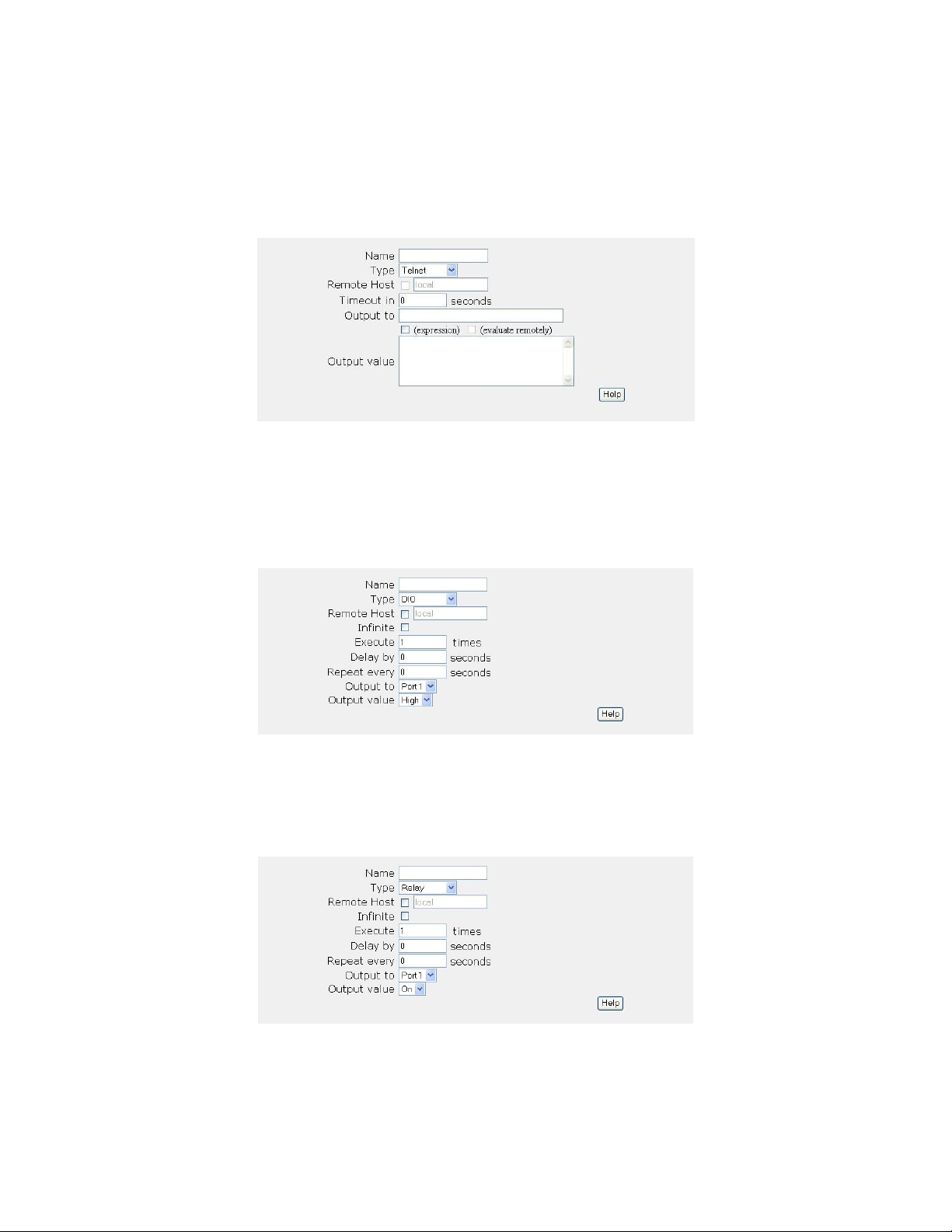
There are no repeat values for Telnet Actions. The Action will execute only once each time the owning
Event is triggered.
Use the “Timeout in” value to have the Action abort, if it doesn’t complete before the time-out period
expires.
DIO
A DIO Action sends an Output Value of “High” or “Low” to the specified port. The state of the DIO port
will change only if the port is set as an output. You can check whether a port is set as an input or output
using the DIO diagnostics (see Digital I/O Diagnostics, page 46).
Relay
A Relay Action turns a relay on or off. Set the “Output value” to the state you want the Action to set the
relay to.
IR Port
IR Port Actions send learned IR Commands (see IR Learning, page 41) to the specified port. The IR
Page 68
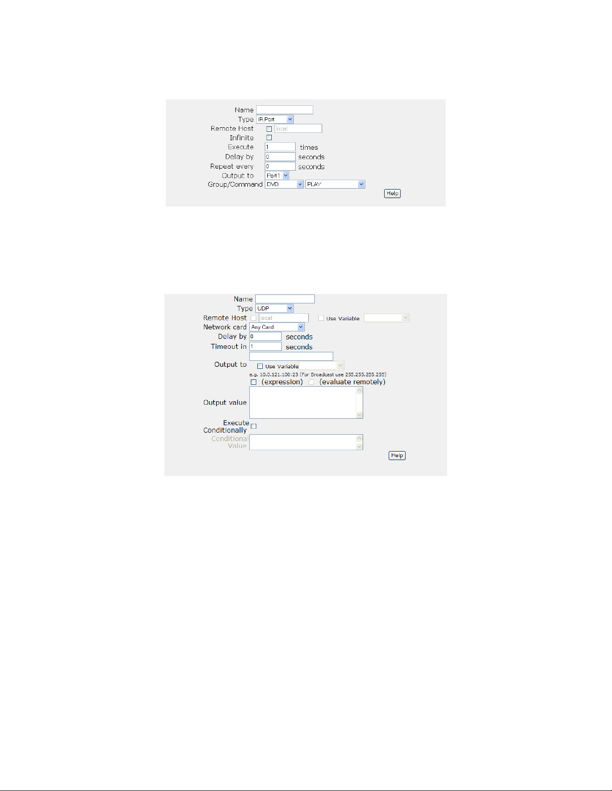
Command to execute must be specified by its Group name and Command name.
UDP
UDP Actions allow information to be sent to a device which use the UDP as its means of communication
via LAN.
PJLink
PJLink action, also known as Projector link, is an action that allows easy communication to a PJLink
device via LAN. Instead of typing in protocols just pick from the pull down list of available commands
and the WACI will do the rest.
Page 69
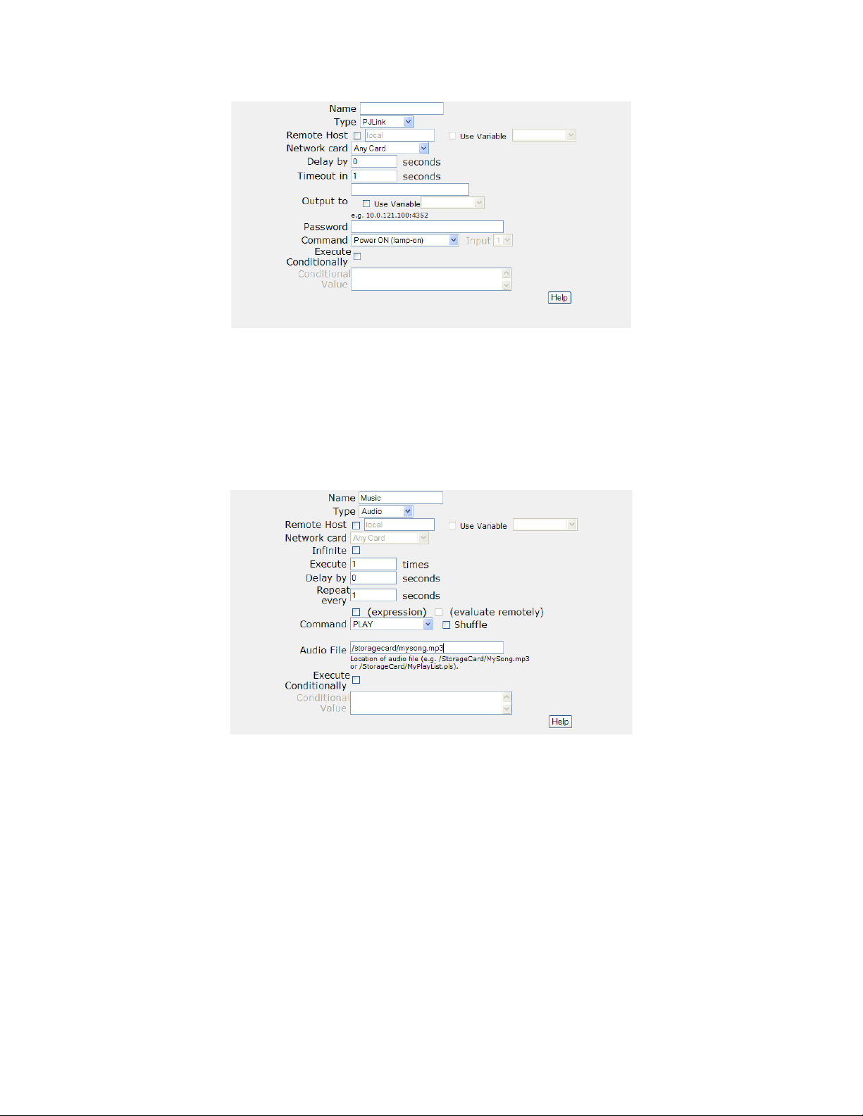
Audio
Audio Actions can play, stop, pause, change rate, skip tracks, change volume, and position. In addition,
the audio action can work off of playlists stored on the WACI to simplify playback sequences.
Action Timing Options
Actions may be:
• Infinite - execute forever, or until another Action cancels the Event. Two notes: first,
checking the “Infinite” checkbox will override the “Execute” number of times field. Second,
the associated Event will remain triggered unless another Action cancels the Event.
• Executed a particular number of times. Actions may be specified to execute as many as 2
times. This field is not used if the “Infinite” check box is CHECKED.
31
Page 70

• Delayed by as many as 228 seconds. The value can be a real number, e.g. 2.5 for 2500
milliseconds. If the Action is repeated any number of times, this delay only applies to the
first run.
• Repeated every N seconds, where N can be a maximum of 228 seconds. The value can be a
real number, as opposed to an integer, e.g. 2.5 for 2500 milliseconds. N applies to the time
period before the second and all subsequent runs. For remote Actions, this value doubles as a
network timeout value as well.
• Aborted if they don’t complete within a defined time-out period. This applies only to HTTP,
Telnet, and E-mail Actions.
Remote Actions
When connecting two or more WACIs up to a system, one of the WACIs can be used to control the other
WACI. The controlling (or local) WACI would then manage the state of the hardware on the remote
(slave) WACI. To set an Action to be performed on the remote WACI, check the “Remote” check box
and specify the host name or IP address of the remote WACI. To make setup easier, make sure that both
the controlling WACI and remote WACI are connected to the network and powered up.
Network Timeouts
By default, Actions that communicate over a network (E-mail, Telnet, HTTP Post, and remote Actions)
timeout after 30 seconds if no connection can be made to the remote server or remote WACI. You can
control the timeout value by entering a non-zero value into the “Repeat every” edit box for remote
Actions or into the “Timeout in” edit box for E-mail, Telnet, and HTTP Post Actions. Setting the
“Execute N times” value to 1 and the “Repeat every” value to 3 for a remote Action would cause the
Action to perform its operation once, but fail if it couldn’t complete it within 3 seconds.
Setting proper timeout values helps reduce the overhead of the Event Manager’s network functions.
Remote Actions running on another WACI on the Local network could use a low time-out value, e.g. 2
seconds; whereas, Actions run on a remote WACI connected through a public network might have a
higher timeout value, e.g. 10 seconds.
Page 71
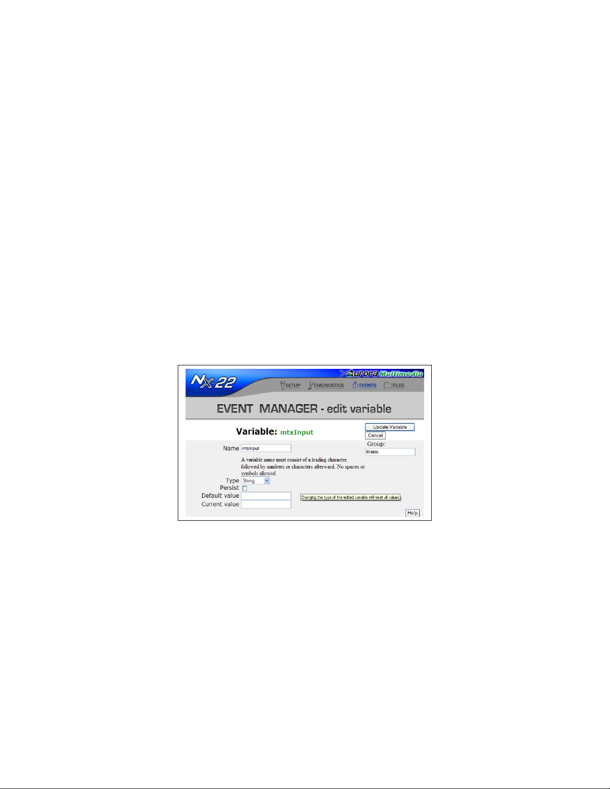
Variables
Variables are used to store information that can be retrieved or acted upon by the Event Manager, or by
calls to RPC functions (see Variable Methods, page 161). You can create Variables that hold temporary
data, or configure them to keep their value even when the WACI is reset. You can also use Variables to
store data to be used by your own Web interface or Flash application stored on the WACI. Use the RPC
calls to access the Variables within Flash, or VB Script to access them within an HTML page.
Variables are created independently of Events or Actions, and any Variable may be used in any Event or
Action; however, a Variable may not be deleted until it is cleared from all the Events or Actions that use
it.
Creating and Editing Variables
Variables may be created from the main Event Manager web page (see The Event Manager Web Page,
page 55) by selecting the “Add variable” button. To edit an existing Variable, first select it so that it is
highlighted, then select the “Edit” button above the list of Variables. The “edit variable” screen allows
you to specify options and values for a Variable.
Some options for Variables will differ by the type of Variable. The options common to all Variables are
Persistence, Default Value, and Current Value.
Group Name
Use the Group field to help organize Variables into meaningful groups. Enter any text into this field. On
the main Event Manager page, click on the Group label at the top of the Variable list to sort the Variables
by their Group name.
Persistence
When the persistence flag (“Persist” check box) is set, the “Current value” of the Variable will be stored
to permanent storage whenever it is changed. This value will persist through a system reset or power
Page 72

failure, so the Default Value is not used when the “Persist” check box is CHECKED.
The storage of the Current Value does take some time, since it is stored into flash. Therefore, if a
Variable is changed often, such as a counter, the WACI will perform more efficiently if you set a Default
Value, and UNCHECK the “Persist” check box.
Default Value
The “Default value” is copied to the “Current value” whenever the system starts up. The start-up
typically occurs from a system reset or a power failure. If a Variable has the persistent flag set, the
“Default value” is not used.
Current Value
The “Current value” is the working value of the Variable. It is the value accessed in all Event and Action
expressions. In addition, Variable Actions (see Variable, page 64) send their outputs to the “Current
value”.
The “Current value” is set to the “Default value” during system start-up, if the Persistent flag is not set.
Types of Variables
Number
A Number Variable can have an integer value between -231 and +231-1.
Schedule
A Schedule Variable can have a time value, specified by [hour]:[minute]:[second] [AM/PM]
fields.
String
A String Variable can be a Unicode string up to 128 characters in length.
Page 73
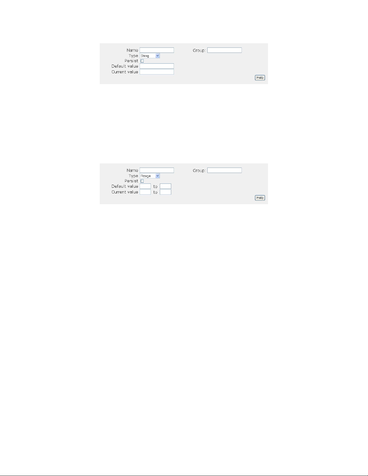
Range
A Range Variable specifies a range of values between a minimum and maximum value. Each value can
be a number between -231 and +231-1. The maximum value should be greater than the minimum.
Range Variables have one other parameter, which is calculated from the minimum and maximum values.
The de-bounce value, displayed after the maximum value, is used to provide a small measure of
hysteresis to prevent flutter.
Functions
Note: ALL FUNCTIONS ARE CASE SENSITIVE!!!
Note: You can utilize decimal, hex, binary, and octal integers for functions as exampled here:
CHAR(66) = CHAR(0x42) = CHAR(0b1000010) = CHAR(0o102) = ‘B’
The following functions are available for use when the expression check box is checked in one of the
supported actions. The following types of actions support expressions: Variable, Serial, IR Serial, HTTP
Post, Email, Log, and Telnet interpreting Values as Expressions
• ASCII (Char) Returns the ASCII numeric value for a character passed in. Example:
ASCII(“A”), ASCII(var_name). Example: varstring = CHAR(66)
• atof(string) Returns floating-point number
Converts a numeric string with floating-point to a floating-point number. Example:
atof(“test”)
• atol(string) or atoi(string) Returns integer
Converts a numeric string to a number. Range of input number: 0 to 2147483647. Example:
atoll(“test”) or atoi(“test”)
• BinToSum(binary Stream) - adds all of the bytes of a binary data stream and returns the sum
Page 74

• bincpy(binary_data, Start, Count) - returns ‘count’ bytes of binary data starting at ‘start’.
• binlen(binary_data) - - returns the number of bytes of binary data
• CHAR(integer) Returns string
Converts a integer to a ASCII character. Range of input number: 0 to 255. Example:
varstring = CHAR(65)
varstring = ‘A’
• ftoa(float) Returns string
Converts an floating-point number to a string representation of the number. Example:
ftoa(3.14)
• GetAudioVolume() Returns integer
Gets the currently set system volume level in a range from 0 - 31 (31 being the loudest and 0
being almost silent).
• GetTrackLength() Returns integer
Gets the total track duration in milliseconds.
• GetTrackPosition() Returns Integer
Gets the current track position in milliseconds.
• GetSystemTime() Returns the current time
If assigned to a Number, then returns the number of milliseconds since the start of the day.
Assigning the return value to a String gives the date and time in text form. Example:
GetSystemTime()
• HEX (Char) Returns a HEX string that represents the character value passed in. Example:
HEX(“A”), HEX(var_name).
• LStr(string, integer) Returns string
Return integer number of characters from the left of string. Example:
LStr(“abcdef”,3) returns “abc”
• ltoa(integer) or itoa(integer) Returns string
Converts an integer to a string representation of the integer. Domain of return number:
-2147483648 to 2147483647. Example:
ltoa(31) or itoa(31)
• Ltrim(string) Returns string
Remove leading spaces from string. Example:
Ltrim(“ test”) returns “test”
• Mod(interger,divisor) Returns remainder of division. Ex: mod(10,3) = 1
• Padl(string, Length) Returns string
Pads a string with spaces on the left to the length specified. Returns a string. If Length
is less than the length of String, then String is returned. Example:
Padl(“ test”, 4)
• Padr(string, Length) Returns string
Pads a string with spaces on the right to the length specified. Returns a string. If Length
is less than the length of String, then String is returned. Example:
Padr(“test “, 6)
• rand(min, max) Returns integer
Page 75

Generates a random number between 0 and 32,767 seeded by the number of milliseconds since
the device boot.
• replace(String, S1, S2) Search string for findstr and replace with newstr. If the string S1
cannot be found inside of String, just return the original string. Example:
replace(“abcdef”,”xyz”,”abc”) returns “abcdef”.
If the string to replace occurs more than once, replace each instance. Example:
replace(“abcabcabc”,”bc”,”Z”) returns “aZaZaZ”.
• RStr(string, integer) Returns string
Return integer number of characters from the right of string. Example:
string=“abcdef”, RStr(string,3)=“def”
• rstrstr(string, string2find) Returns integer
Searching Right to Left, finds string2find inside of string and returns the beginning location
of string2find.
Failure to find returns -1. Example:
string=“abcabc”, string2find=“bc”, returns 4
• Rtrim(string) Returns string
Removes trailing spaces from string. Example:
Rtrim(“ test”) returns “test”
• strlen(string) Returns Integer
Returns the number of characters in the string. Example:
strlen(“test”) returns “4”
• strlwr(string) Returns string
Returns the lower case version of a string. Example:
strlwr(“TEST”) returns “test”
• strstr(string, string2find) Returns integer
Searching Left to Right, finds string2find inside of string and returns the beginning
location of string2find.
Failure to find returns -1. Example:
string=“abcdef” string2find=“bc” = returns 1
• StrToBin(string) - converts a string to a binary data stream, and returns the binary data stream
• strupr(string) Returns string
Returns the upper case version of a string. Example:
strupr(“test”) returns “TEST”
• substr(String, StartChar, NumOfChars) Returns string. Example:
substr(“abcdef”,2) or substr(“abcdef”,2,0) returns “cdef”
• Trim(string) Returns string
Remove leading and trailing spaces from string. Example:
Trim(“ test “) returns “test”
Page 76

Expressions
Trigger Values for Events and Output Values for Actions may be written as expressions (instead
of constant values) by checking the “(expression)” flag. Evaluating expressions is described in
this section.
Interpreting Values as Expressions
If the “(expression)” option is UNCHECKED, the trigger and output values are treated as simple strings,
and no quotation marks are needed. (NOTE: Variable Events and Actions automatically interpret the
value based on its output or input Variable’s type (see Types of Variables, page 72).
On the other hand, if the “(expression)” option is CHECKED, the WACI will treat the values as an
expression and evaluate them before triggering or sending an output.
In an expression, any string values must now be in quotes; otherwise, the token will treated as an
identifier. For example:
• “Hello” (in quotes) is a string value in the expression.
• Hello (without quotes) is an identifier for a Variable.
Special characters inside string values (inside quotes) must be escaped (see Escaping Special Characters,
page 85) or URL encoded (see Send String, page 44).
Evaluation of Expressions
Expressions are evaluated strictly left-to-right. Order of operations is NOT supported; however,
parentheses may be used to prioritize the execution of the expression.
In addition, the type of operation (string, integer, etc) and the final value of the expression are determined
by the first token. If a string cannot be resolved to an integer during an integer operation, it takes on the
value of 0 (zero).
Some examples:
This expression... ... resolves to this
value.
3+4*5 35
3+(4*5) 23
“Hello”*3 “HelloHelloHello”
“Hello”+3 “Hello3”
Notes
No order of operations.
Priority is indicated by
parentheses.
* is a string operator here.
The number 3 becomes
part of the “Hello” string
because the string comes
first.
Page 77

This expression... ... resolves to this
Hello+3 7
3+”6” 9
3+”Hello” 3
Operators
The operators that are supported are:
• Arithmetic operations: +, -, *, /
• Logical comparison operators: ==, != , <, <=, >, >=
Notes
value.
Assuming Hello is a
number Variable holding a
value of 4.
The string “6” is valued as
6, a number, and 3 is a
number.
The string is treated as 0
because “Hello” has no
integer interpretation.
• Logical operators: &&, ||, !
• Bitwise operators: &, | , ~,^
• Range operator: in
• Assignments: =, +=, -=, *=, /=, &=, |=
Addition/Plus (+) Operator
The ‘+’ operator is used to append one string to another, or to add two integer values together.
Adding a number to a string will produce a string with the number (as text) appended to the end. Adding
a string to a number results in just the number (unless the string contains a value that can be converted to
a number).
For example:
This expression... ... resolves to this value.
3+4 7
“Hello”+” “+”There” “Hello There”
“Hello”+3 “Hello3”
3+”Hello” 3
3+”6” 9
Page 78

Subtraction/Minus (-) Operator
The subtraction operator works with both numerical values and strings values. Use this operator with
strings to remove a sub-string from a source string, or use this operator to subtract two integer values.
For example:
This expression... ... resolves to this value.
6-2 4
“Hello”-”ll” “Heo”
10-”3” 7
Multiplication/Times (*) Operator
This operator multiplies two numbers, or can be used for creating a string with a repeating value. The
numbers and strings can be either Variables or literals.
For example:
This expression... ... resolves to this value.
4*5 20
“Hello”*3 “HelloHelloHello”
3*”Hello” 0
Division/Divide (/) Operator
The divide operator is valid only for numerical values and Variables. Use this operator to divide one
numerical value by another. The resultant type is an integer value. If the denominator is 0, then the
operation evaluates to 0.
For example:
This expression... ... resolves to this value.
10/3 3
10/2 5
10/0 0
Equal Comparison (==) Operator
The equal comparison operator will compare two tokens, which can be strings or integers. The
expression will return 1 if the two tokens are equivalent, and 0 if they are not.
String values can be compared against wildcard values, e.g. “Hello*”.
For example, assuming MyNumber has an integer value of 4, and MyName has a string value of
Page 79

“John”:
This expression... ... resolves to this value.
MyNumber==4 1
MyNumber==“4” 1
MyNumber==5 0
MyName==“John” 1
MyName==“J*” 1
0==“John” 1
Not-Equal Comparison (!=) Operator
The not-equal comparison operator will compare two tokens, which can be strings or integers. Exactly
opposite to the equal comparison operator, the expression will return 0 if the two tokens are equivalent,
and 1 if they are NOT equal.
String values can be compared against wildcard values, e.g. “Hello*”.
For example, assuming MyNumber has an integer value of 4, and MyName has a string value of
“John”:
This expression... ... resolves to this value.
MyNumber!=4 0
MyNumber!=“4” 0
MyNumber!=5 1
MyName!=“John” 0
MyName!=“??ul” 1
0!=“John” 0
Greater-Than Comparison (>) Operator
The greater-than comparison operator will compare two tokens, which can be integers or strings
(assuming the string represents an integer value). The expression will return 1 if the first token has a
larger integer value than the second, and 0 if the second value is larger or equal.
For example, assuming MyNumber has an integer value of 4:
This expression... ... resolves to this value.
MyNumber>5 0
MyNumber>4 0
MyNumber>3 1
Page 80

Greater-Than or Equal Comparison (>=) Operator
The greater-than or equal comparison operator will compare two tokens, which can be integers or strings
(assuming the string represents an integer value). The expression will return 1 if the first token has an
integer value larger than or equal to the second, and 0 if the second value is larger.
For example, assuming MyNumber has an integer value of 4:
This expression... ... resolves to this value.
MyNumber>=5 0
MyNumber>=4 1
MyNumber>=3 1
Less Than Comparison (<) Operator
The less-than comparison operator will compare two tokens, which can be integers or strings (assuming
the string represents an integer value). The expression will return 1 if the first token has a smaller value
than the second, and 0 if the second value is smaller or equal.
For example, assuming MyNumber has an integer value of 4:
This expression... ... resolves to this value.
MyNumber<5 1
MyNumber<4 0
MyNumber<3 0
Less Than or Equal Comparison (<=) Operator
The less-than or equal comparison operator will compare two tokens, which can be integers or strings
(assuming the string represents an integer value). The expression will return 1 if the first token has an
integer value smaller than or equal to the second and 0 if the second value is smaller.
For example, assuming MyNumber has an integer value of 4:
This expression... ... resolves to this value.
MyNumber<=5 1
MyNumber<=4 1
MyNumber<=3 0
Logical-And (&&) Operator
Assume you have two Boolean (true/false) expressions, Expression1 and Expression2, each
Page 81

returning true (1) or false (0). The logical-and operator determines the true or false state of the complex
expression Expression1&&Expression2 using the rules applying to a traditional logical AND
statement:
If Expression1
is...
True (1) True (1) True (1)
True (1) False (0) False (0)
False (0) True (1) False (0)
False (0) False (0) False (0)
and
Expression2
is...
Expression1&&Expression2
resolves to...
In other words:
This expression... ... resolves to this value.
(3==3)&&(4==4) 1
1&&(4==5) 0
0&&(4==4) 0
(3==6)&&0 0
Logical-Or (||) Operator
Assume you have two Boolean expressions, Expression1 and Expression2, each returning true
(1) or false (0). The logical-or operator determines the true or false state of the complex expression
Expression1||Expression2 using the rules applying to a traditional logical OR statement:
In other words:
If Expression1
is...
True (1) True (1) True (1)
True (1) False (0) True (1)
False (0) True (1) True (1)
False (0) False (0) False (0)
This expression... ... resolves to this value.
(3==3)||(4==4) 1
1||(4==5) 1
0||(4==4) 1
(3==5)||0 0
and
Expression2
is...
Expression1&&Expression2
resolves to...
Page 82

Logical-Not (!) Operator
The logical-not is a prefix operator that “negates” the Boolean expression that follows it. In other words,
if Expression1 returns true (1), !Expression1 returns false (0).
For example:
This expression... ... resolves to this value.
!0 1
!(4==3) 1
!(“Hello”==“Hello”) 0
Bitwise-And (&) Operator
The bitwise-AND operator performs the logical AND operation bit by bit between two integers. This is
better understood by looking at the example of 12&10. The binary value of 12 is 1100,
and the binary value of 10 is 1010. 12&10 is computed by performing
an AND between each of the corresponding four bits:
12: 1 1 0 0
10: 1 0 1 0
12&10: 1 0 0 0
Therefore: 12&10 = (Binary) 1000 = (Decimal) 8
Bitwise-Or (|) Operator
The bitwise-OR operator performs the logical OR operation bit by bit between two integers. This is
better understood by looking at the example of 12|10. The binary value of 12 is 1100,
and the binary value of 10 is 1010. 12|10 is computed by performing
an OR between each of the corresponding four bits:
12: 1 1 0 0
10: 1 0 1 0
12|10: 1 1 1 0
Therefore: 12|10 = (Binary) 1110 = (Decimal) 14
One's Complement (~) Operator
The one's complement operator is a bitwise-not prefix operator that performs a logical NOT to each bit of
an integer. This is better understood by looking at the example of ~5. The binary value of 5
is 101. ~5 is computed by performing a NOT on each of the three bits:
Page 83

5: 1 0 1
~5: 0 1 0
Therefore: ~5 = (Binary) 010 = (Decimal) 2
Realize that the bitwise not is performed on a 32-bit value, e.g. ~0 converts to a 32-bit value with all bits
in the integer set to 1. To get just the bits you want, you should AND the result with the bits of interest,
e.g. ~5 & 7.
Range (in) Operator
The ‘in’ operator compares a numerical value or Variable against a range Variable. The resultant type is
an integer value of either 0 or 1. If the value is within the range, 1 is returned; otherwise, 0 is returned.
For example, assume Count has a value of 15, Range10 has a value of 1 to 10, and Range20 has a value
of 1 to 20
This expression... ... resolves to this value.
Count in Range10 0
Count in Range20 1
Assignment (=) Operator
The ‘=’ operator stores a value (R-Value) into a Variable (L-Value). The value on the left of the
assignment operator is the L-Value. The result of the assignment is an R-value, and cannot be used in
another assignment, though it can be used as the result of an expression.
For example:
This expression... ... resolves to this value.
3=4 Illegal (L-Value not a
Variable)
MyCounter=1 1 (also stores 1 into
the MyCounter Variable)
5==(MyCounter=1) 0 (stores 1 into
MyCounter as well)
Addition Assignment (+=) Operator
The ‘+=’ operator is used to append one string to another, or to add two integer values together.
Adding a number to a string will produce a string with the number (as text) appended to the end. Adding
a string to a number results in just the number (unless the string contains a value that can be converted to
a number).
For example, assuming MyNumber has an integer value of 4, and MyString has a value of “Hello”:
Page 84

This expression... ... resolves to this value.
MyNumber+=4 7 (MyNumber also
contains 7)
MyString+=3 “Hello3” (MyString also
contains “Hello3”)
3+=“6” Illegal (L-Value not a
Variable)
Subtraction Assignment (-=) Operator
The subtraction assignment operator works with both numerical values and strings values. Use this
operator with strings to remove a sub-string from a string Variable, or use this operator to subtract an
integer value from a numeric Variable.
For example, assuming MyNumber has an integer value of 4, and MyString has a value of “Hello”:
This expression... ... resolves to this value.
MyNumber-=1 3 (MyNumber also
contains 3)
MyString-=“ll” “Heo” (MyString also
contains “Heo”)
10-=“3” Illegal (L-Value not a
Variable)
Multiplication Assignment (*=) Operator
This operator multiplies two numbers, or can be used for creating a string with a repeating value. The
numbers and strings can be either Variables or literals.
For example, assuming MyNumber has an integer value of 4, and MyString has a value of “Hello”:
This expression... ... resolves to this value.
MyNumber*=5 20 (MyNumber set to 20)
MyString*=3 “HelloHelloHello”
(MyString same as
result)
3*=5 Illegal (L-Value not a
Variable)
Division Assignment (/=) Operator
The divide operator is valid only for numerical values and Variables. Use this operator to divide one
numerical value by another. The resultant type is an integer value. Division by 0 results in a return value
of 0.
Page 85

For example, assuming MyNumber has an integer value of 4:
This expression... ... resolves to this value.
MyNumber/=3 1 (MyNumber is also 1)
MyNumber/=0 0 (MyNumber is also 0)
Bitwise-And Assignment (&=) Operator
The bitwise-and assignment operator performs the logical AND operation bit by bit between an integer
Variable and another integer. The result of the operation is stored in the L-Value of the operator. Refer to
the Bitwise-And operator for an example of the bitwise AND.
Bitwise-Or Assignment (|=) Operator
The bitwise-or assignment operator performs the logical OR operation bit by bit between an integer
Variable and another integer. The result of the operation is stored in the L-Value of the operator. Refer to
the Bitwise-Or operator for an example of the bitwise OR.
Wildcard Characters
There are two special characters used to match one or more characters in a comparison string:
‘*’ Matches one or more characters
‘?’ Matches any single character
Either character can be used anywhere within a string constant. When used with a comparison operator,
“he*”, “*llo”, “he*o”, and “he??o” will all match the string “hello”.
When used to compare “\g” data within a serial or Telnet stream, the use of ‘?’ is more efficient, since the
total number of comparison characters can be known. Use of the ‘*’ could require buffering large
amounts of the incoming data.
Wildcard characters are not limited to expressions only. They can be used within simple text values
(values where the expression check-box is not checked).
Escaping Special Characters
Escape characters can be placed anywhere in an expression, though the expression will fail to evaluate if
the escape character causes an invalid expression. The escape character should be placed within quotes
when defining an expression, e.g. “\m”. Quotes are not needed if the “(expression)” check box is
UNCHECKED for the Event or Action. Valid escape codes are:
Code Name Description
\a bell alert Character code: 0x07
\b Backspace Character code: 0x08
Page 86

Code Name Description
\d Date Represents the date as a string:
MM/DD/YYYY
\f Form feed Character code: 0x0C
\g Trigger data Data that triggered the current Event
\m Time Time that the current Event was triggered
at: HH:MM:SS in 24hr format
\n New line or linefeed Character code: 0x0D
\o Origin that triggered
Event
\r Carriage return Character code: 0x0A
\t Horizontal tab Character code: 0x09
\v Vertical tab Character code: 0x0B
\' Single quote Character code: 0x27
\” Double quote Character code: 0x22
\\ Backslash Character code: 0x5C
\? Question mark this is needed, because wild cards will be
\* Asterisk Character code: 0x2A
Port number, Variable name, etc. The
value depends on the type of Event.
identified by * and ? within the string.
Page 87

XIV. Remote Procedure Calls
Remote procedure calls (RPCs) are used to control a WACI using another WACI, or using a client
computer. You can turn on and off the relays, send e-mail, add Events and Actions, etc. Anything the
WACI can do can be configured or controlled through the RPC interface.
The WACI supports RPCs for most web interfaces, including HTML, Flash (.fla), and Active Server
Pages (.asp). Methods are typically called using the HTTP Post syntax for HTML and Flash, and
Visual Basic scripting for Active Server Pages.
Calls to the RPC server using HTTP post are done through the /rpc virtual directory, e.g.
http://waci/rpc. Use this directory as part of the URL when creating the address for the HTTP post
transaction.
This RPC reference covers:
• RPC Server Logs
• Syntax for HTTP Post
• Fault Codes
• Flash Example
• Visual Basic Scripting
• Note on Error Checking
• RPC Quick Reference to Methods
• Detailed List of All Methods
RPC Server Logs
As noted in Diagnostics web pages section, key information regarding the RPC server can be retrieved
from the Log Files web page. This information includes the RPC server version and a list of available
methods. The Log Files web page also allows you to enable logging for the RPC commands.
Syntax for HTTP Post
Call Tokens
Methods may be called using HTTP Post using the following call tokens:
• version - The RPC server version may be obtained through the Log pages in the Admin Web
Pages. This token is entirely optional and may be safely omitted from the call.
• encoding - Number of times that the parameters (param1..paramN values) have been URL
encoded. Some web applications URL encode the parameters more than one time. Use this
optional parameter to define the number of times that the RPC server should decode the
parameters. By default, this value is set to 1.
• method - Name of the method to call.
• param[i] - Value for parameter #i, where i is an integer.
Page 88

General format for a call using HTTP Post:
[version=[ RPC Server Version ]&]method=[ Method to Call ]
[&encoding=[ Count ]][¶m1=[ Value for Parameter 1 ]¶m2=[ Value for
Parameter 2 ]¶m3=[ Value for Parameter 3, etc...]]
See the detailed list of methods at the end of this reference for the method name and the values for
param1, param2, etc. These parameter values are denoted by the text “[in]” in the Syntax and
Parameters sections.
Response Tokens
The response tokens are:
• status - 0 for Failure, 1 for Success
• faultCode - If status is 0 (failure). faultCode will be an integer representing a specific error
(see Fault Codes). This token is NOT returned if status is 1 (success).
• response[i] - Returned value #i, where i is an integer. If status is 0 (fail), the value for
response1 will be a string describing the failure, and the value for response2 will be a debug
string giving more information about the failure.
Returned values are strings, integers, or Booleans, depending on the method. See the detailed list of
methods at the end of this reference for details about the returned values for any given method. These
returned values are denoted by the text “[out, retval]” in the Syntax and Parameters sections.
The response to the HTTP Post will be a string in the format:
status=[ 0 or 1 ][&faultCode=[Fault Code]] [&response1=[ Value for
Response 1 ] &response2=[ Value for Response 2 ] &response3=[ Value for
Response 3, etc...]]
EXAMPLE #1: Serial_GetSettings
Let us look at the method Serial_GetSettings (defined on page 112). From the Syntax and
Parameter sections, we can tell that param1 is a long integer that specifies either serial port #1 or #2.
We can also see that response1 (retval, or return value) is a string describing the settings for the given
port.
Using the HTTP Post format, the call to obtain settings from serial port #2 is:
version=2.0&method=Serial_GetSettings¶m1=2
Since the version token is optional, this call may be simplified:
method=Serial_GetSettings¶m1=2
A sample response for this call:
status=1&response1=9600,8,ODD,2,1,SOFTWARE
Responses are not usually used in its raw string format. A web programmer will typically parse the
response before displaying or otherwise making use of the information received.
Page 89

EXAMPLE #2: Net_GetSubnetMask
The call for the Net_GetSubnetMask method:
method=Net_GetSubnetMask
Sample response:
status=1&response1=255.255.255.0
Fault Codes
Fault Code Fault Description
1 Function parameter out of range / item specified does not
exist
2 Timed out waiting for a mutex or shared resource
3 Memory allocation failure
4 Configuration does not support action (i.e. setting a Digital
I/O output when it is configured as an input)
5 Failed to find entry in database (registry or FRAM)
6 Failed to store persistent database (registry or FRAM),
settings might not be saved
7 Some internal error occurred that does not fit another
category. Must use extended error information to
diagnose.
8 An expected file format was invalid
9 IR signal too strong, receiver is overloaded
10 IR signal too weak
11 Other IR capture error
Page 90

Using Macromedia Flash
You may access all WACP RPCs using HTTP post. In Flash, you may accomplish this using LoadVars{}
and sendAndLoad(). An example for making these calls follows.
STEP 1: Pass WACI IP Address to Flash
To begin, you must pass the IP address of WACI to your Flash file. There is more than one way to do
this, but below, we describe one sample method using JavaScript. NOTE: In this script, the .html and
.swf files must reside on the WACI to determine the IP address.
First, at the top of the .html file in which you are embedding your flash file (here, the name of the file is
“MyWACIShockWaveFlashFile.swf”), insert this bit of script:
<script type=“text/javascript” language=“JavaScript”>
thispage = location.href;
URLarr = thispage.split(“/”);
theIP = URLarr[2];
theFILE = “MyWACIShockWaveFlashFile.swf”;
</script>
Next, use this bit of script to embed the flash file in the desired area of the web page:
<script type=“text/javascript” language=“JavaScript”>
document.write('<object id=“WACI” classid=“clsid:D27CDB6EAE6D-11cf-96B8-444553540000”
codebase=“http://download.macromedia.com/pub/shockwave/cabs/flash/swflash.
cab#version=6,0,29,0” width=“100%” height=“100%”>');
document.write('<param name=“movie” value=“'+theFILE+'“
/>');
document.write('<param name=“quality” value=“high” />');
document.write('<param name=“FlashVars”
value=“callerID='+theIP+'“ />');
document.write('<embed name=“flashMovie” src=“'+theFILE+'“
FlashVars=“callerID='+theIP+'“ quality=“high”
pluginspage=“http://www.macromedia.com/go/getflashplayer”
type=“application/x-shockwave-flash” width=“100%” height=“100%”></embed>');
document.write('</object>');
</script>
The IP Address may now be accessed from your Flash action scripts in the Variable “callerID”.
Page 91

STEP 2: Call RPC with HTTP Post
Once you have the IP address, you are able to access the RPC server. Load the method and it's
parameters into a LoadVars() object as shown below, then make the call with sendAndLoad().
// Get WACI IP
RPCServerIP = [callerID, or whatever you used to get the IP address of the
WACI];
// Initialize Call & Response Tokens
WACI_Call = new LoadVars()
WACI_Response = new LoadVars()
// Set up RPC method and parameters you desire to call.
// Note that these are all URL-encoded strings.
// You may assign values based on buttons, text fields, constants, or
whatever else is appropriate for your page.
WACI_Call.method = “[Desired RPC Method]”;
WACI_Call.param1 = “[Parameter 1 for the Method]”;
WACI_Call.param2 = “[Parameter 2 for the Method]”;
WACI_Call.param3 = “[Parameter 3 for the Method]”;
[etc.]
// Call the RPC using HTTP Post
WACI_Call.sendAndLoad(“http://”+RPCServerIP+”/RPC”, WACI_Response, POST);
STEP 3: Response Tokens
At this point, if you used the script template above, you may now examine, use, and/or display the
contents of:
WACI_Response.status
WACI_Response.faultCode
WACI_Response.response1
WACI_Response.response2
WACI_Response.response3
[etc.]
The response tokens, like methods and call tokens are all in the form of URL-encoded strings.
Page 92

Visual Basic Scripting
To access an RPC using Visual Basic, first create a WACI object of type “WACI.UserAPI.1”. Then, call
the method with the object, specifying any parameters in parentheses. For example, this script in an
Active Server Page retrieves the IP address of the WACI and the settings for serial ports 1 and 2.
Dim waciUser
Dim strIP, strErr
Dim strPort1, strPort2
set waciUser = CreateObject(“WACI.UserAPI.1”)
strIP = waciUser.Net_GetIPAddress
if(strIP = ““) then
strErr = waciUser.GetLastErrorString
end if
strPort1 = waciUser.Serial_GetSettings(1)
strPort2 = waciUser.Serial_GetSettings(2)
Some notes:
• Parameters and returned values are strings, integers, or Booleans, depending on the method.
• The above example includes error checking for Net_GetIPAddress. Methods will report
errors based on the type of its return value. Strings will return the null string, integers will
return -1, and Booleans will return FALSE.
• See the detailed list of methods at the end of this reference for details about the parameters
and return values for any given method. Parameter values are denoted by the text “[in]” in
the Syntax and Parameters sections. Similarly, the return value is denoted by the text
“[out, retval]”.
• String values should be passed in as URL encoded values. Returned strings are also URL
encoded.
Note on Error Checking
The HRESULT, referred to in the Syntax of each method, ALWAYS returns “S_OK”, so it is not useful
in error checking.
Instead, use the error checking values described in the HTTP Post and Visual Basic above, and the Error
Information Methods below (see Error Information Methods, page 100) to perform meaningful error
checks.
Errors are based on the type of a function’s out/retval value. On error, a string retval is returned
as a NULL string, an integer retval returns -1, and Booleans will return FALSE.
Page 93

RPC Quick Reference
I. QUICK CONTENTS................................................................................................................................................ 3
II. FULL CONTENTS..................................................................................................................................................4
III. INTRODUCTION..................................................................................................................................................6
IV. BOX CONTENTS.................................................................................................................................................. 7
BOX CONTENTS FOR THE NX-22......................................................................................................................................7
V. HARDWARE SPECIFICATIONS........................................................................................................................ 8
GENERAL SPECIFICATIONS................................................................................................................................................ 8
ABSOLUTE MAXIMUM RATINGS FOR HARDWARE...............................................................................................................10
HARDWARE PARTS OVERVIEW........................................................................................................................................11
NX-22 Parts Overview.........................................................................................................................................11
DETAILED HARDWARE DESCRIPTIONS.............................................................................................................................. 12
Power Indicator and LCD................................................................................................................................... 12
Power Adapter..................................................................................................................................................................... 12
Power Port........................................................................................................................................................................... 12
Green Power........................................................................................................................................................................ 12
LCD Display....................................................................................................................................................................... 12
Access Boot Menu.............................................................................................................................................................. 12
Serial Ports.......................................................................................................................................................... 12
Serial Ports 1 & 2................................................................................................................................................................ 12
Serial Port Pin-Out Diagram............................................................................................................................................... 13
LED Indicators for Serial Ports 1 & 2................................................................................................................................. 13
RS-422 Operation:............................................................................................................................................................... 13
RS-485 Operation:............................................................................................................................................................... 13
Network Interface.................................................................................................................................................14
LAN Port............................................................................................................................................................................. 14
LED Indicators.................................................................................................................................................................... 14
Relays ..................................................................................................................................................................14
Relay Ports 1&2.................................................................................................................................................................. 14
LED Indicators for Relay Ports 1&2................................................................................................................................... 14
Digital I/O 1&2....................................................................................................................................................15
Digital Input........................................................................................................................................................................ 15
Digital Output...................................................................................................................................................................... 15
I/O GROUND Line............................................................................................................................................................. 15
LED Indicators for I/O Ports (1&2).................................................................................................................................... 15
IR Ports................................................................................................................................................................15
IR Emitters.......................................................................................................................................................................... 16
IR Ports................................................................................................................................................................................ 16
LED Indicators for IR Ports ............................................................................................................................................... 16
IR Learner............................................................................................................................................................16
IR Learner Port.................................................................................................................................................................... 16
IR Learner LED................................................................................................................................................................... 16
VI. EXPANSION HARDWARE ..............................................................................................................................17
VII. FACTORY DEFAULT CONFIGURATIONS......................................................................................... 18
DEFAULT NETWORK SETTINGS FOR LAN 1 & 2.............................................................................................................. 18
DEFAULT SERIAL SETTINGS............................................................................................................................................18
DEFAULT I/O SETTINGS ................................................................................................................................................18
VIII. QUICK START.................................................................................................................................................19
Page 94

STEP 1: POWERING UP................................................................................................................................................19
STEP 2: DETERMINING WACI CONNECTION..................................................................................................................20
STEP 3A: CONNECTING THE NX-22 TO A LAN............................................................................................................20
STEP 3B: DIRECT CONNECTION IF STATIC IP IS SET ......................................................................................................21
STEP 3C: DIRECT CONNECTION WITH A SERIAL CABLE................................................................................................... 21
STEP 4: ACCESS THE WACI.......................................................................................................................................21
STEP 5: CONFIGURE WACI USING THE ADMIN WEB PAGES...........................................................................................22
IX. USING THE WACI..............................................................................................................................................23
TESTING HARDWARE..................................................................................................................................................... 23
UPLOADING FIRMWARE UPGRADES..................................................................................................................................23
VIEWING SERVER LOGS.................................................................................................................................................24
AUTOMATING TASKS (THE EVENT MANAGER)..................................................................................................................24
UPLOADING CUSTOM WEB PAGES...................................................................................................................................24
USING REMOTE PROCEDURE CALLS (RPCS)....................................................................................................................25
X. WEB SERVER FEATURES.................................................................................................................................26
XI. BOOT MENU REFERENCE..............................................................................................................................27
ACCESSING THE BOOT MENU WITH A SERIAL CONNECTION.................................................................................................27
0: DISPLAY CURRENT SETTINGS......................................................................................................................................27
1: RESTORE FACTORY DEFAULTS....................................................................................................................................28
2: CONFIGURE IP SETTINGS........................................................................................................................................... 28
3: CHANGE PASSWORD..................................................................................................................................................29
4: SET HOST NAME......................................................................................................................................................29
5: DOWNLOAD NEW FIRMWARE......................................................................................................................................29
6: LAMP TEST..............................................................................................................................................................30
7: MEMORY TEST.........................................................................................................................................................30
8: ERASE FILE SYSTEM..................................................................................................................................................30
9: OEM FUNCTIONS.....................................................................................................................................................30
XII. ADMIN WEB PAGES........................................................................................................................................31
SETUP......................................................................................................................................................................... 32
Firmware Version................................................................................................................................................32
Date / Time...........................................................................................................................................................33
Time Zone.............................................................................................................................................................33
MAC Address.......................................................................................................................................................33
Network Settings.................................................................................................................................................. 34
SMTP Server Address..........................................................................................................................................34
System Password..................................................................................................................................................34
IP Access Table....................................................................................................................................................35
Port Setup.............................................................................................................................................................37
SQL Setup.............................................................................................................................................................37
DIAGNOSTICS................................................................................................................................................................38
System Information.............................................................................................................................................. 39
IR Settings............................................................................................................................................................40
IR Diagnostics..................................................................................................................................................................... 40
IR Learning......................................................................................................................................................................... 41
IR Learning Tips................................................................................................................................................................. 43
Managing Learned Commands........................................................................................................................................... 43
Serial Port Diagnostics........................................................................................................................................43
Serial Send & Receive Histories......................................................................................................................................... 43
Send String.......................................................................................................................................................................... 44
Relay Diagnostics................................................................................................................................................ 45
Digital I/O Diagnostics........................................................................................................................................46
Log Files.............................................................................................................................................................. 46
RPC Server Info.................................................................................................................................................................. 47
Page 95

RPC Server Commands....................................................................................................................................................... 47
Event Manager Log............................................................................................................................................................. 47
FTP Server Connections & Commands.............................................................................................................................. 47
Web Server.......................................................................................................................................................................... 47
Firmware..............................................................................................................................................................48
EVENTS (SEE SECTION: THE EVENT MANAGER)................................................................................................................49
FILES...........................................................................................................................................................................49
File Structure.......................................................................................................................................................50
EventManager..................................................................................................................................................................... 51
IR......................................................................................................................................................................................... 51
wwwpub.............................................................................................................................................................................. 51
Allowable File Types............................................................................................................................................51
Uploading Files................................................................................................................................................... 52
XIII. THE EVENT MANAGER................................................................................................................................54
OVERVIEW OF EVENTS, ACTIONS, & VARIABLES...............................................................................................................54
THE EVENT MANAGER WEB PAGE..................................................................................................................................55
EVENTS....................................................................................................................................................................... 57
Creating and Editing Events................................................................................................................................57
Types of Events.................................................................................................................................................... 57
Clock................................................................................................................................................................................... 57
Timer................................................................................................................................................................................... 58
Variable............................................................................................................................................................................... 58
Serial.................................................................................................................................................................................... 58
DIO (Digital Input/Output)................................................................................................................................................. 59
Startup................................................................................................................................................................................. 59
Telnet................................................................................................................................................................................... 59
Network............................................................................................................................................................................... 60
IR Input............................................................................................................................................................................... 60
Named Event....................................................................................................................................................................... 60
Other Event Options............................................................................................................................................ 61
Group Name........................................................................................................................................................................ 61
Execute Actions Concurrently............................................................................................................................................ 61
Expression........................................................................................................................................................................... 61
Trigger Value...................................................................................................................................................................... 61
Remote Events..................................................................................................................................................................... 61
ACTIONS......................................................................................................................................................................63
Creating and Editing Actions...............................................................................................................................63
Types of Actions...................................................................................................................................................64
Variable............................................................................................................................................................................... 64
Serial.................................................................................................................................................................................... 64
Event.................................................................................................................................................................................... 65
E-Mail.................................................................................................................................................................................. 65
HTTP Post........................................................................................................................................................................... 65
Log...................................................................................................................................................................................... 66
Telnet................................................................................................................................................................................... 66
DIO...................................................................................................................................................................................... 67
Relay.................................................................................................................................................................................... 67
IR Port................................................................................................................................................................................. 67
UDP..................................................................................................................................................................................... 68
PJLink.................................................................................................................................................................................. 68
Audio................................................................................................................................................................................... 69
Action Timing Options.........................................................................................................................................69
Remote Actions.....................................................................................................................................................70
Network Timeouts................................................................................................................................................ 70
VARIABLES...................................................................................................................................................................71
Creating and Editing Variables...........................................................................................................................71
Group Name........................................................................................................................................................................ 71
Persistence........................................................................................................................................................................... 71
Default Value...................................................................................................................................................................... 72
Page 96

Current Value...................................................................................................................................................................... 72
Types of Variables................................................................................................................................................72
Number................................................................................................................................................................................ 72
Schedule.............................................................................................................................................................................. 72
String................................................................................................................................................................................... 72
Range................................................................................................................................................................................... 73
FUNCTIONS...................................................................................................................................................................73
Note: ALL FUNCTIONS ARE CASE SENSITIVE!!!...........................................................................................73
Note: You can utilize decimal, hex, binary, and octal integers for functions as exampled here:.......................73
The following functions are available for use when the expression check box is checked in one of the supported
actions. The following types of actions support expressions: Variable, Serial, IR Serial, HTTP Post, Email,
Log, and Telnet interpreting Values as Expressions........................................................................................... 73
EXPRESSIONS................................................................................................................................................................76
Interpreting Values as Expressions..................................................................................................................... 76
Evaluation of Expressions....................................................................................................................................76
Operators.............................................................................................................................................................77
Addition/Plus (+) Operator................................................................................................................................................. 77
Subtraction/Minus (-) Operator........................................................................................................................................... 78
Multiplication/Times (*) Operator...................................................................................................................................... 78
Division/Divide (/) Operator............................................................................................................................................... 78
Equal Comparison (==) Operator........................................................................................................................................ 78
Not-Equal Comparison (!=) Operator................................................................................................................................. 79
Greater-Than Comparison (>) Operator.............................................................................................................................. 79
Greater-Than or Equal Comparison (>=) Operator............................................................................................................. 80
Less Than Comparison (<) Operator................................................................................................................................... 80
Less Than or Equal Comparison (<=) Operator.................................................................................................................. 80
Logical-And (&&) Operator............................................................................................................................................... 80
Logical-Or (||) Operator....................................................................................................................................................... 81
Logical-Not (!) Operator..................................................................................................................................................... 82
Bitwise-And (&) Operator.................................................................................................................................................. 82
Bitwise-Or (|) Operator....................................................................................................................................................... 82
One's Complement (~) Operator......................................................................................................................................... 82
Range (in) Operator............................................................................................................................................................. 83
Assignment (=) Operator..................................................................................................................................................... 83
Addition Assignment (+=) Operator................................................................................................................................... 83
Subtraction Assignment (-=) Operator................................................................................................................................ 84
Multiplication Assignment (*=) Operator........................................................................................................................... 84
Division Assignment (/=) Operator..................................................................................................................................... 84
Bitwise-And Assignment (&=) Operator............................................................................................................................ 85
Bitwise-Or Assignment (|=) Operator................................................................................................................................. 85
Wildcard Characters............................................................................................................................................85
Escaping Special Characters...............................................................................................................................85
XIV. REMOTE PROCEDURE CALLS...................................................................................................................87
RPC SERVER LOGS......................................................................................................................................................87
SYNTAX FOR HTTP POST..............................................................................................................................................87
Call Tokens.......................................................................................................................................................... 87
Response Tokens..................................................................................................................................................88
EXAMPLE #1: Serial_GetSettings...................................................................................................................... 88
EXAMPLE #2: Net_GetSubnetMask....................................................................................................................89
FAULT CODES.............................................................................................................................................................. 89
USING MACROMEDIA FLASH...........................................................................................................................................90
STEP 1: Pass WACI IP Address to Flash............................................................................................................90
STEP 2: Call RPC with HTTP Post.....................................................................................................................91
STEP 3: Response Tokens....................................................................................................................................91
VISUAL BASIC SCRIPTING...............................................................................................................................................92
NOTE ON ERROR CHECKING........................................................................................................................................... 92
RPC QUICK REFERENCE............................................................................................................................................... 93
ERROR INFORMATION METHODS....................................................................................................................................100
Page 97

GetLastErrorCode ( ).........................................................................................................................................100
GetLastErrorString ( )....................................................................................................................................... 100
GetLastExtendedErrorString ( )........................................................................................................................ 100
GENERAL INFORMATION METHODS................................................................................................................................101
AllState_Get ( ).................................................................................................................................................. 101
GetMachineType ( )........................................................................................................................................... 101
GetFirmwareVersion ( ).....................................................................................................................................101
ValidatePassword ( Password ).........................................................................................................................102
Time_GetDate ( )............................................................................................................................................... 102
Time_Sleep ( Milliseconds )...............................................................................................................................103
NETWORK METHODS...................................................................................................................................................104
Net_GetNetCardCount ( )..................................................................................................................................104
Net_GetIPAddress ( ).........................................................................................................................................104
Net_GetIPAddressEx ( NetCard )......................................................................................................................104
Net_GetSubnetMask ( )......................................................................................................................................104
Net_GetSubnetMaskEx ( NetCard )...................................................................................................................105
Net_PostHtmlData ( Url, PostData ).................................................................................................................105
Net_PostHtmlDataEx ( NetCard, Url, IsExpression, PostData, Timeout ).......................................................105
Net_SendMail( SenderId, ToIds, CcIds, BccIds, Subject, MessageBody )........................................................106
Net_SendMailEx ( NetCard, SenderId, ToIds, CcIds, BccIds, ReturnPathId,
ReturnRcpId, MsgComment, Subject, IsExpression, MessageBody )................................................................106
TELNET METHODS.......................................................................................................................................................108
Telnet_Send ( NetCard, Msg, MaxWaitMS )..................................................................................................... 108
Telnet_SendExpression ( NetCard, Expression, MaxWaitMS ).........................................................................108
Telnet_Read ( NetCard )....................................................................................................................................108
Telnet_ClearReadBuffer ( NetCard ).................................................................................................................109
Telnet_ReadBufferCount ( NetCard )................................................................................................................109
LOGGING METHODS.................................................................................................................................................... 109
Log_Write ( FileName, IsExpression, Buffer, MaxSize )...................................................................................109
Log_ReadFile ( FileName, MaxLength )...........................................................................................................110
Log_ClearFile ( FileName ).............................................................................................................................. 110
Log_FirstFile ( Wildcard ).................................................................................................................................110
Log_NextFile ( Wildcard ).................................................................................................................................111
SERIAL METHODS....................................................................................................................................................... 112
Serial_GetSettings ( Port ).................................................................................................................................112
Serial_Send ( Port, Msg, MaxWaitMS ).............................................................................................................112
Serial_SendExpression ( Port, Expression, Data )............................................................................................113
Serial_Read ( Port )...........................................................................................................................................113
Serial_ClearReadBuffer ( Port )........................................................................................................................113
Serial_ReadBufferCount ( Port ).......................................................................................................................114
Serial_GetPortCount ( ).....................................................................................................................................114
RELAY METHODS........................................................................................................................................................115
Relay_On ( Port )...............................................................................................................................................115
Relay_Off ( Port )...............................................................................................................................................115
Relay_GetState ( Port )......................................................................................................................................115
Relay_GetPortCount ( ).....................................................................................................................................116
DIGITAL I/O METHODS............................................................................................................................................... 117
DIO_Read ( Port )............................................................................................................................................. 117
DIO_OutputMode_Close ( Port )...................................................................................................................... 117
DIO_OutputMode_Open ( Port ).......................................................................................................................117
DIO_IsOutput ( Port )........................................................................................................................................118
DIO_IsPulledUp ( Port )................................................................................................................................... 118
DIO_GetPortCount ( ).......................................................................................................................................118
IR METHODS............................................................................................................................................................. 119
IR_SendCommand ( Port, Group, Command )..................................................................................................119
IR_SendCommandEx ( Port, Group, Command, Sequence, Repeat )............................................................... 119
Page 98

IR_SendData ( Port, Sequence, Data )..............................................................................................................120
IR_ListAllGroups ( ).......................................................................................................................................... 121
IR_ListAllCommandsInGroup ( Group )...........................................................................................................122
IR_ListAllCommands ( ).................................................................................................................................... 122
IR_GetGroupMake ( Group ).............................................................................................................................122
IR_GetGroupModel ( Group )...........................................................................................................................123
IR_GetGroupRemote ( Group )......................................................................................................................... 123
IR_GetGroupComment ( Group )......................................................................................................................124
IR_GetPortCount ( ).......................................................................................................................................... 124
EVENT MANAGER METHODS........................................................................................................................................ 125
IsEventManagerEnabled ( )...............................................................................................................................125
EnableEventManager ( Enable )....................................................................................................................... 125
WaitOnChangeEvent ( ChangeMask, TimeOut )...............................................................................................125
EVENT METHODS........................................................................................................................................................127
AddEvent ( Name, Type, Concurrent, Source, Match )..................................................................................... 127
AddRemoteEvent ( Client, EventRecord )..........................................................................................................127
CloneEventById ( EventId, CloneActions, NewName ).....................................................................................128
DeleteEventById ( EventId ).............................................................................................................................. 128
DeleteEventByName ( Name )........................................................................................................................... 129
GetEventByIdx ( Idx ).........................................................................................................................................129
GetEventByName ( Name )................................................................................................................................129
GetEventConcurrent ( EventId )........................................................................................................................130
GetEventCount ( )..............................................................................................................................................130
GetEventGroup ( EventId )................................................................................................................................131
GetEventNetCard ( EventId ).............................................................................................................................131
GetEventHost ( EventId )...................................................................................................................................131
GetEventIds ( )...................................................................................................................................................132
GetEventIdxById ( EventId )..............................................................................................................................132
GetEventInfo ( EventId )....................................................................................................................................132
GetEventMatch ( EventId )................................................................................................................................ 133
GetEventName ( EventId ).................................................................................................................................134
GetEventOption ( EventId, OptionType )...........................................................................................................134
GetEventSchClockType ( EventId )....................................................................................................................134
GetEventSchRecurType ( EventId )................................................................................................................... 135
GetEventSchMaskOrDay ( EventId ).................................................................................................................135
GetEventSchMonth ( EventId ).......................................................................................................................... 136
GetEventSchYear ( EventId ).............................................................................................................................136
GetEventSchRecurEveryN ( EventId )...............................................................................................................137
GetEventSchHour ( EventId )............................................................................................................................ 137
GetEventSchMinute ( EventId )......................................................................................................................... 138
GetEventSchSecond ( EventId ).........................................................................................................................138
GetEventSource ( EventId )............................................................................................................................... 138
GetEventType ( EventId )...................................................................................................................................139
SetEventById ( EventId, Name, Type, Concurrent, Source, Match ).................................................................139
SetEventByName ( Name, Type, Concurrent, Source, Match )......................................................................... 140
SetEventNetCard ( EventId, NetCard )..............................................................................................................141
SetEventOption ( EventId, OptionType, OptionVal ).........................................................................................141
SetEventSchedule ( EventId, Recur, MaskOrDay, Month, Year, RecurEveryN, Hour, Minute, Second ).........143
SortEvents ( SortType, Direction ).....................................................................................................................144
TriggerEventByName ( Name, Time, Source, Data ).........................................................................................144
ACTION METHODS...................................................................................................................................................... 146
AddActionByEvId ( EventId, Name, Type, Delay, DutyCycle, StopAfter, Port, Output )..................................146
AddActionByEvName ( EventName, Name, Type, Delay, DutyCycle, StopAfter, Port, Output )......................147
DeleteActionById ( ActionId )............................................................................................................................147
DeleteActionByIdx ( EventId, Idx )....................................................................................................................148
DeleteActionByName ( EventId, Name )............................................................................................................148
Page 99

GetActionByIdx ( EventId, Idx ).........................................................................................................................149
GetActionByName ( EventId, Name )................................................................................................................ 149
GetActionCount ( EventId )............................................................................................................................... 149
GetActionDelay ( ActionId ).............................................................................................................................. 150
GetActionDutyCycle ( ActionId ).......................................................................................................................150
GetActionHost ( ActionId )................................................................................................................................ 150
GetActionIds ( EventId ).................................................................................................................................... 151
GetActionInfo ( ActionId )................................................................................................................................. 151
GetActionName ( ActionId )...............................................................................................................................152
GetActionOption ( ActionId, OptionType )........................................................................................................152
GetActionOutput ( ActionId ).............................................................................................................................152
GetActionPort ( ActionId ).................................................................................................................................153
GetActionStopAfter ( ActionId ).........................................................................................................................154
GetActionType ( ActionId )................................................................................................................................154
MoveActionByIdx ( EventId, Idx, Where )......................................................................................................... 155
SetActionById ( ActionId, Name, Type, Delay, DutyCycle, StopAfter, Port, Output )...................................... 156
SetActionByIdx ( EventId, Idx, Name, Type, Delay, DutyCycle, StopAfter, Port, Output )...............................157
SetActionByName ( EventId, Name, Type, Delay, DutyCycle, StopAfter, Port, Output )..................................157
SetActionHost ( ActionId ).................................................................................................................................158
SetActionOption ( ActionId, OptionType, OptionVal )......................................................................................159
SortActions ( SortType, Direction )................................................................................................................... 159
VARIABLE METHODS...................................................................................................................................................161
AddVariable ( Name, Type, Default, Value, Persist )........................................................................................161
AssignVariable ( VarName, IsExpression, Value )............................................................................................162
DeleteVariableById ( VarId ).............................................................................................................................162
DeleteVariableByName ( Name ).......................................................................................................................162
GetVariableByIdx ( Idx )....................................................................................................................................163
GetVariableByName ( Name )...........................................................................................................................163
GetVariableCount ( )......................................................................................................................................... 163
GetVariableDefault ( VarId ).............................................................................................................................164
GetVariableGroup ( VarId ).............................................................................................................................. 164
GetVariableName ( VarId )............................................................................................................................... 164
GetVariablePersist ( VarId )..............................................................................................................................165
GetVariableType ( VarId ).................................................................................................................................165
GetVariableValue ( VarId )............................................................................................................................... 166
SetVariableById ( VarId, Name, Type, Default, Value, Persist ).......................................................................167
SetVariableByName ( Name, Type, Default, Value, Persist )............................................................................167
SetVariableGroup ( VarId, Group )...................................................................................................................168
SortVariables ( SortType, Direction )................................................................................................................169
XV. LIMITED 3 YEAR WARRANTY...................................................................................................................170
XVI. FCC PART 15 STATEMENT........................................................................................................................171
XVII. INDEX.............................................................................................................................................................172
Page 100

Error Information Methods
GetLastErrorCode ( )
Returns the fault code from the last failed method call.
Syntax
HRESULT GetLastErrorCode(
[out, retval] long* Code
);
Parameters
Code [out, retval] Integer representing fault code.
Remarks
The value of Code corresponds to faultCode of an HTTP Post response when status is 0 (failure).
See {see Error: Reference source not found, page Error: Reference source not found} for a list of defined codes.
GetLastErrorString ( )
Returns the description of the error from the last failed method call.
Syntax
HRESULT GetLastErrorString(
[out, retval] BSTR* ErrorString
);
Parameters
ErrorString [out, retval] String describing an error.
Remarks
ErrorString corresponds to response1 of an HTTP Post response when status is 0 (failure).
GetLastExtendedErrorString ( )
Returns an extended description of the error from the last failed method call.
Syntax
HRESULT GetLastExtendedErrorString(
[out, retval] BSTR* ExtErrorString
);
Parameters
ExtErrorString [out, retval] String giving more information about an error.
Remarks
Corresponds to response2 of an HTTP Post response when status is 0 (failure).
 Loading...