

Aurora Audio GTQ2 MKIII, GTQ2 Mark 3 Instruction Sheet
AURORA AUDIO INTERNATIONAL
1520 NORTH CAHUENGA BOULEVARD
HOLLYWOOD, CA90028
EMAIL: Info@auroraaudio.net Telephone: 323 462 6136
Web Site: http://www.auroraaudio.net Fax : 323 462 6137
GTQ2 Mark 3 Instruction Sheet
Introduction:
Well done for purchasing a hand-built, all discrete class A circuitry GTQ2 stereo microphone preamplifier! It is designed to give you years of superb sounds and service. Improvements on the Mark 3
include an extra mid frequency (1600Hz) to provide choices of 400, 1600 and 3200Hz, and impedance
switching (300Ω and 1200Ω) on the XLR inputs.
Unpacking Instructions:
Carefully remove the unit from the custom foam packing and fit the fuse into the fuse-holder. The
GTQ2 uses a power supply that automatically senses the local voltage so no setting is required. For best
noise performance always use a grounded 3 core / 3 pin a.c. cord. If you connect the GTQ2 to an
unbalanced destination, either use the ¼” rear jack or wire to the XLR pins 2 and 3 only. Leave pin 1
high. This will help prevent ground loops.
The rear jack sockets are mono and should be connected with a mono jack. If a balanced TRS jack is
plugged in, there will be a 6dB loss as there would be no signal on the ring contact.
Operating Guide:
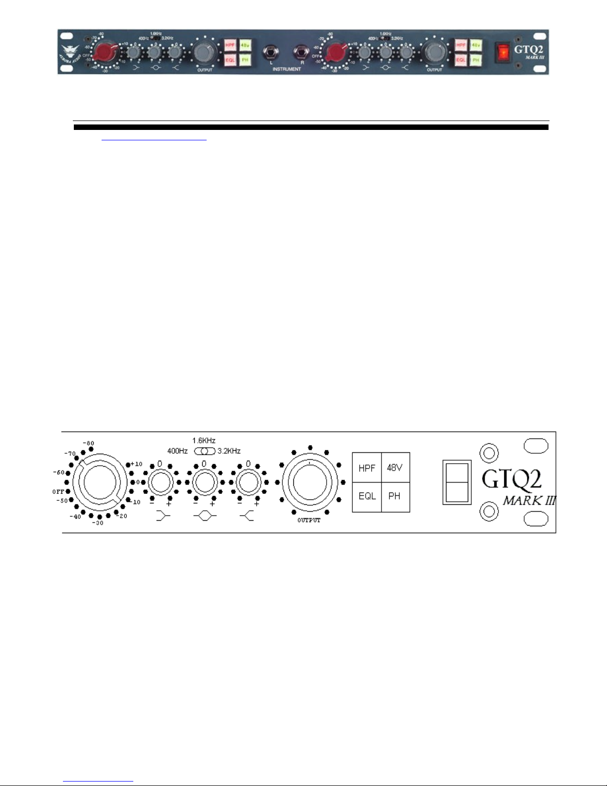
The GTQ2 front panel is shown above. In order for the equalizer to work, the “EQL” button must be
selected and the high pass filter, which rolls off frequencies below 80Hz, is selected when both “EQL”
and “HPF” buttons are pressed.
The “48v” button applies 48 volts dc to the mic input XLR in order to power condenser microphones.
Despite urban legends to the contrary, 48v does not harm ribbon or dynamic microphones but damaged
microphone cables might... so always check that your cables are in good condition!
The “PH” button inverts the phase 180 degrees and should be used to correct any phase issues created
by the mic position or any outboard equipment. Press the button and, if the stereo image sounds weird
with it pressed, you know the phasing is OK and to leave the switch off!

The GTQ2 can accommodate any signal you care to throw at it, including high-level line inputs. The
sensitivity switch provides gain adjustment from +80dB to –10dB and the level pot allows for fine
adjustments. The level pot has an audio taper and is –20dB at half rotation. I would recommend using
the level pot between ¾ and full rotation and never below ½ rotation unless part of a deliberate fade. If
you have to turn the pot below ½ way, the sensitivity switch can be adjusted at least 4 clicks less!
Operating the unit in this fashion ensures that you keep the headroom in the designed 26dB region.
The D.I. input has 10 Megohm input impedance and around 10dB gain. It can be used (to great effect)
with musical instrument pickups, but works equally well with high-level signals like a D.A.T. or CD
player. The same gain structure rules apply.
If a keyboard or similar ac powered device is connected to the DI input and causes a ground loop, make
a cable with a male XLR connector such that signal goes to pin 2, shield to pin 3 and no connection to
pin 1. The GTQ2's transformer balanced input will resolve the ground loop issue.
The impedance switch on the rear panel selects either 300Ω or 1,200Ω input impedances. Most of the
time you will find that the 1,200Ω input works best with dynamic and condenser microphones but very
low impedance microphones (e.g. ribbon type) may work better with the 300Ω input. The 300Ω input
provides 6dB additional gain if sourced from a low impedance, but if a higher impedance microphone
is used (e.g. close to 300Ω), the series impedance will create a 6dB attenuator that negates the 6dB
gain. The switch enables the user to experiment with which input impedance best matches the
microphone.
Using analogue equipment in a digital world!
E.G. Analogue versus Digital levels
In my technical/design background in analogue circuitry, spanning over 30 years, the levels of audio
were calibrated in dBm, a throwback from the telephone and communications era where 0dBm was
1mW dissipated into a 600 ohm load = 0.775 volts. 0dBm was later changed for the more convenient
0dBu which is a voltage into any specified impedance.
In a broadcast studio, Peak Program Meters were used that were calibrated from 2 to 7. Mark #4
equated to 0dBu and Mark #6 equated to +4dBu.
The level +4dBu is 1.228 volts a.c. and also the 0VU reference point on a VU meter. This is,
coincidentally, #6 on the PPM meter and a typical line up level for an analogue tape machine.
Most consoles and pre-amplifiers have a maximum output level before clipping of around 26dBu. This
gives them 22dB headroom above 0VU = +4dBu. Driving the console and pre-amplifier “hotter” than
+4dBu output reduces the headroom proportionately.
At the other end of the scale, the consoles/pre-amplifiers usually have +80dB gain and produce noise
figures in the –45 to –48dBu region and an Equivalent Input Noise of -125 to -128dBu. The noise floor
from a 200 ohm source at 20 degrees C is –129dBu so the amplifier is adding 1dB of noise to the
absolute noise floor. As the gain is reduced, the difference between the signal and the noise floor
widens as the noise is pushed further down.
Reminder:- Increasing the gain amplifies the signal AND raises the noise floor.
Running the device at hotter levels than usual reduces the headroom.
 Loading...