

Page 1
AURORA AUDIO INTERNATIONAL
1520 NORTH CAHUENGA BOULEVARD
HOLLYWOOD, CA90028
EMAIL: [email protected] Telephone: 323 462 6136
Web Site: http://www.auroraaudio.net Fax : 323 462 6137
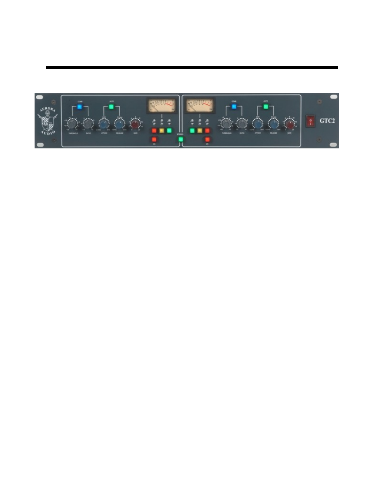
Aurora Audio GTC2 Dual Compressor
Owner's Manual
Table of contents :-
1. Introduction
2. Rear panel connections, audio and power connections
3. Front panel controls
4. Specifications
5. Tips for user
6. Warranty and ROHS directives
1. Introduction
Congratulations on your purchase of this hand-built, all class A circuitry, dual
compressor. It has been designed to be a very comprehensively equipped tool in the
quest for great sounding audio production.
Care has been taken to make the unit very easy to use with detented and color coded
control knobs/potentiometers, illuminated pushbuttons for all mode switching, and big,
illuminated, Sifam VU meters to provide indication of output level and gain reduction.
The unit is built in a robust, all steel, 19” x 2U case and has custom transformer floating
and balanced audio interfaces via XLR connectors. Each channel has its own fully
regulated, voltage, current and temperature protected, power supplies and low noise is
1
Page 2

facilitated by the use of Mu-metal encased input transformers and a custom, low emf
radiation, toroidal ac power transformer.
The unit is designed to give years of reliable service.
2. Rear Panel Connections
Power is supplied via an industry standard IEC power connector.
The GTC2 power supply automatically senses the voltage of the ac current you connect
it to.
The fuse is a 1 amp anti-surge (slow blow) 20mm x 5mm. Anti-surge fuses must be used
due to the momentary inrush current to the toroidal power transformer.
The GTC2 MUST be connected to a grounded 3 pin power source.
Audio connections are made via 3 pin XLR connectors, wired pin 2 = hot, pin 3 = cold,
and pin 1 = ground.
In the center of the panel is a 1/4” T.R.S. Jack socket. This is the side chain linking
connector to enable the GTC2 to link to other GTC2 compressors and link their side
chains together for multi-channel compression.
Wiring of the connector is tip = Control dc, and sleeve = 0v (ground) common.
2
Page 3
3. Front Panel Controls
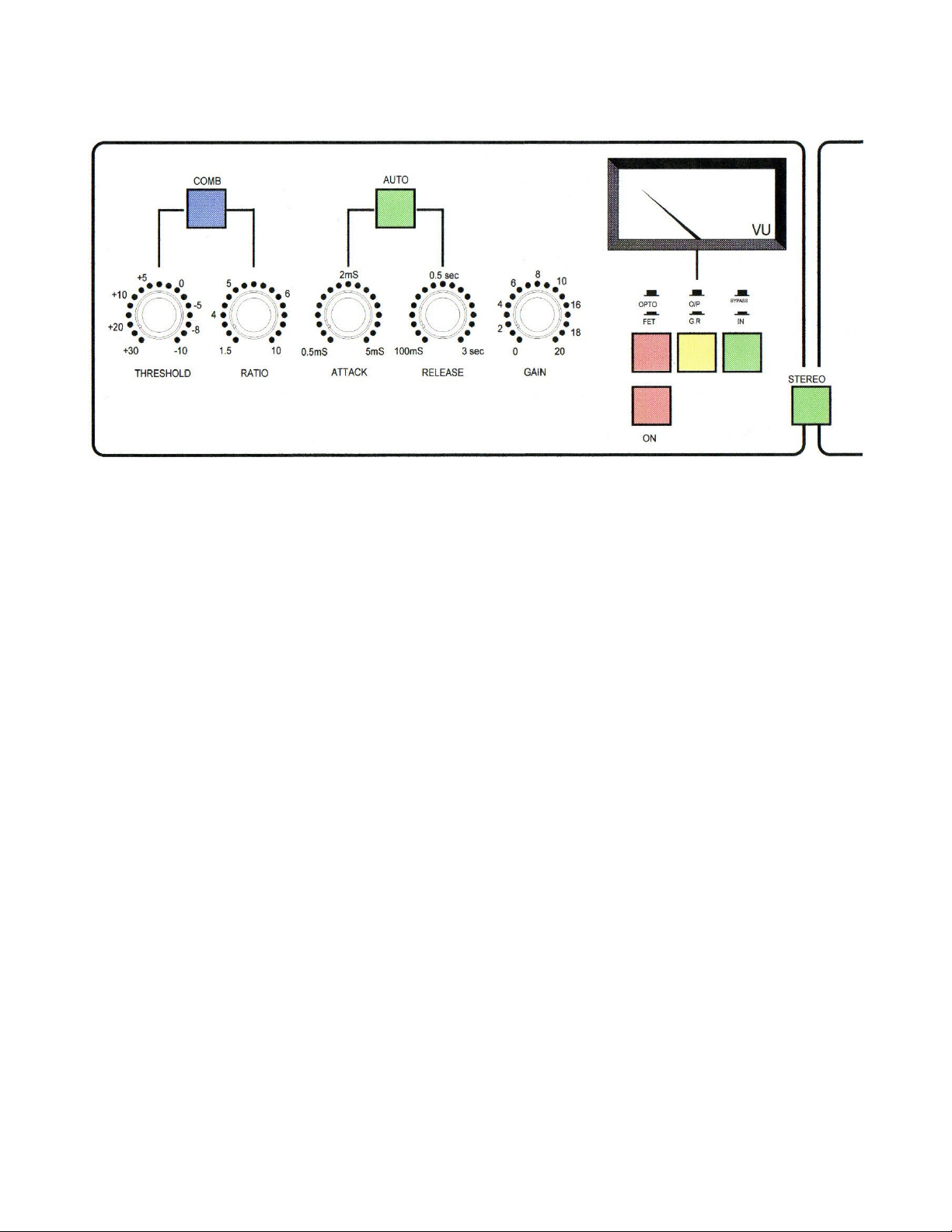
The drawing above shows the left hand channel, the right channel is similar.
The five control potentiometers function as follows :-
NB There is one further small detent at either end of the pot rotation.
Threshold (Grey knob) :- A 17 detented potentiometer with a total range of 40dB, i.e
from -10dBu to +30dBu.
Ratio (Grey knob) :- A 17 detented potentiometer covering a range of ratios from 1.5:1
to 10:1.
Attack (Blue knob) :- A 17 detented potentiometer covering attack times from 500
microseconds to 5 milliseconds.
Release (Blue knob) :- A 17 detented potentiometer covering release times from 100
milliseconds to 3 seconds.
Gain (Red knob) :- A non-detented potentiometer covering gains from 0dB to +20dB.
The silk screened dB incremented scale is accurate and allows for fine level
adjustments.
3
Page 4

The seven illuminated switches are as follows :-
NB. The first item is with the switch off, the second with the switch on.
Bypass/In (Green switch) :- With the switch deselected, there is a hard (relay switched)
connection between the input and output XLRs. This also applies when the unit is
switched off/powered down and means that it could be left in a circuit path without
disturbing continuity.
When bypassed and the power is on, the VU meter and side chains are disabled to
prevent confusing meter information as the audio circuits would be all powered up.
When the button is pressed in, the hard bypass is released and the audio passes through
the unit. The VU meter should indicate the output level where 0VU = +4dBu = 1.228v
ac.
Side Chain Off/On (Red Switch) :- With the switch deselected the side chain is
disconnected from the audio path so that no compression takes place and all the audio
paths work at unity gain. As there are three alternative paths (described in detail later)
this offers ample opportunity to use their different sounding configurations to “sweeten”
or “modify” the sound passing through the compressor.
When the button is pressed in the side chain is activated and the degree of compression
will depend on the relationship between the input signal level, the value of the threshold
and ratio settings, and the mode of compression selected.
Opto/FET (Red Switch) :- The default control element is a photo-resistive opto
coupler whose degree of attenuation is controlled by a d.c. voltage generated by the side
chain. When the button is pressed, the opto path is switched out of circuit and replaced
by one using a FET (Field Effect Transistor) as the control element. Each element has a
particular sound footprint especially when compressing hard.
Output Level/Gain reduction (Yellow Switch) :- The VU meter default mode (switch
deselected) is the output level from the compressor. If the side chain is switched off and
the gain control set to 0dB this reading is also the input level to the compressor.
When the switch is pressed, the VU meter needle will rise to the 0VU point and will
then move backwards, towards the -20VU section of the dial, to indicate the dB's of gain
reduction being applied. As the opto compressor has a different attenuator characteristic
to the FET, you will notice a difference in gain reduction reading when switching from
opto to FET. This is to be expected.
4
Page 5

Auto Release Off/On (Green Switch) :- If the switch is deselected the attack and
release times are set by the two blue potentiometers. The user should always experiment
with the settings of these controls to see how they affect the sound.
When the Auto button is pressed the release time is dependent on the nature of the
program material passing through the compressor. Generally the release times are longer
but, if the material is short bursts of sound, the auto timing capacitor will have less
stored energy and will produce shorter release times. If the material is long, flowing,
rifts then the capacitor will charge up more and produce longer release times. The actual
timing value changing constantly with the nature of the material passing through the
compressor.
Combined Off/On (Blue Switch) :- When deselected the control element is either the
opto or FET path depending on whether the red FET switch is selected.
If the Combined switch is pressed, relays reconfigure the internal circuit paths so that
both control elements are in circuit. The signal passes first through the opto path and is
then applied to the FET path for additional control. As both paths are unity gain before
compression, there will be little difference in compression until both sections start
working hard and then it will be seen to compress as much as another 6dB. In Combined
mode the meter will read gain reduction automatically with no option for O/P level.
The Combined mode's main function is not just to squash the living daylights out of a
signal but rather to provide the user with a third option of sound signature. When the
Combined switch is used, try having the Threshold and Ratio controls at minimum and
then gently rotating the Threshold until the gain reduction meter indicates that the side
chain is beginning to work. Listen to the color of the sound at this point and the effect
on that sound by adjusting the other controls. It's a very useful feature!
Stereo Link Off/On (Green Switch) :- If not selected the two compressor channels
work completely independently and can be assigned to different circuit paths with
different degrees of compression.
If the Stereo button is pressed the compressors will work together as a stereo unit (i.e. as
a stereo bus compressor) with whichever channel has the most side chain voltage (i.e the
most compression at that instant in time) taking control over both channels and
providing identical amounts of compression.
The control will pass seamlessly from one channel to the next depending on which of
the two is working hardest and, as a consequence, the stereo image should not drift from
center.
5
Page 6

NB. For the stereo link to function properly, both channels should have the same
control element selected (i.e opto/FET/combined) and the bypass and sidechains
should both be switched to the “on” position.
This can be easily ascertained by comparing the lighted buttons on one channel with the
other.
5. Specifications
Input Impedance = 10Kohm balanced and floating, transformer coupled.
Output Impedance = <75ohm balanced and floating, transformer coupled
Output drive capability = +26dBu into any load of 600 ohms and above
Frequency response = 20Hz to 20KHz ± 1dB
Total Harmonic Distortion = < 0.1% @ +20dBu O/P @ 1KHz
Noise = < -75dB filtered 20Hz to 20KHz
Side chain voltage = Typically between 0v minimum and +10v maximum
(Greater d.c. voltages provide greater compression.)
6. Tips for users :-
Ah, what to expect here?!!! I'm only the designer and feel sure sure that, with minimal
practice, you will be able to email me with tips on good settings for particular
instruments or vocals! I look on the unit as a tool with which I have provided more than
adequate variations for you to sculpt the sound you desire!
As a very general guide/starting point, I suggest the following :-
Threshold = minimum (fully counter clockwise)
Ratio = minimum (fully counter clockwise)
Attack = maximum (fully clockwise)
Release = minimum (fully counter clockwise)
Gain = 0dB (fully counter clockwise)
6
Page 7

Bypass = pressed in
VU = selected to gain reduction (pressed in)
Sidechain = selected to ON (pressed in)
Then, with whatever program material you have, gently rotate the Threshold control
clockwise until you see the VU meter just start to indicate gain reduction. Leave the
Threshold control there and adjust the Ratio, Attack and Release controls for the sound
and compression you want. There's lots of scope for experimentation!
As the degree of compression increases and the signal gets smaller, use the gain control
to restore the level back to the OVU region (with the meter set to output level).
7. Warranty
This unit is guaranteed for a period of 12 months parts and labor from receipt of delivery
of the unit. This is a conditional warranty and does not cover accidental damage from
connecting it to the wrong ac power voltage or from dropping it or other event outside
our control or responsibility. There are no user serviceable components inside the unit
and any attempts at repair are easily detected and void the warranty.
The unit must be returned to us or your local distributor for repair and/or calibration.
ROHS Directives
The RoHS Directive stands for "the restriction of the use of certain
hazardous substances in electrical and electronic equipment". This
Directive bans the placing on the EU market of new electrical and
electronic equipment containing more than agreed levels of lead,
cadmium, mercury, hexavalent chromium, polybrominated biphenyl
(PBB) and polybrominated diphenyl ether (PBDE) flame retardants.
The restrictions took effect in the E.U from 1st July 2006.
It is very important that the owner of any piece of equipment that contains even
microscopic amounts of the listed hazardous substances (in relation to the weight of
the unit) realize that the responsibility of its disposal rests with them. The unit
should not just be thrown away at the end of its lifetime, whether that's 10, 20 or 30
years hence.
7
Page 8

Please contact us at the address below and we will provide you with the necessary
information for proper disposal.
Aurora Audio, 1520 North Cahuenga Boulevard, Hollywood CA90028
Phone +1 323 462 6136 Fax +1 323 462 6137
Email [email protected] Web URL www.auroraaudio.net
8
 Loading...