

Aurora Audio GTP8 User Manual
AURORA AUDIO INTERNATIONAL
1520 NORTH CAHUENGA BOULEVARD
HOLLYWOOD, CA90028
EMAIL: Info@auroraaudio.net Telephone: 323 462 6136
Web Site: http://www.auroraaudio.net Fax : 323 462 6137
GTP8 Instruction Sheet
Introduction:
Well done for purchasing a hand-built, all discrete class A circuitry GTP8 eight channel microphone
pre-amplifier! It is designed to give you years of superb sounds and service.
Unpacking Instructions:
Carefully remove the unit and power supply from the custom foam packing. The power supply
automatically senses your local power voltage and can work between 85v and 265v. For best noise
performance always use a grounded 3 core / 3 pin a.c. cord.
If you connect the GTP8 to an unbalanced destination, wire to the XLR pins 2 and 3 only. Leave pin 1
high. This will help prevent ground loops.
The rear jack sockets are an unbalanced insertion at around -15dBu level.
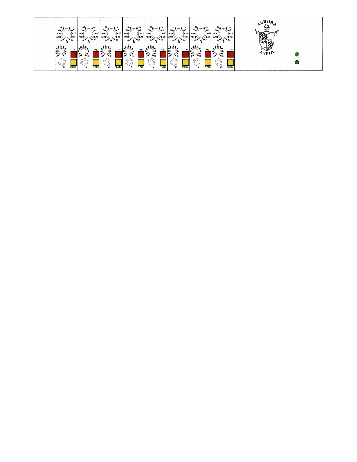
Operating Guide:
The GTP8 can accommodate any signal you care to throw at it, including high-level line inputs. The
sensitivity switch provides gain adjustment in 10dB steps from +80dB to –10dB and the +/- 5dB level
pot allows for fine adjustments of level and also extends the gain range from +85dB down to -15dB.
The GTP8 does not have an output fader as it is anticipated to be used with the channel fader either in
the GTM822 console or the digital workstation the unit is connected to.
It is possible to fit an external fader to the GTP8 by using the rear panel channel insertion jacks. A
10Kohm audio taper fader could be connected as follows :-
Fader top = tip
Fader wiper = ring
Fader bottom = sleeve
The channel insertion jacks are intended to be used with our 8 channel 4 band Equalizer and is not
suitable for connecting to an external patch bay.

The D.I. input has 10 Megohm input impedance and around 10dB gain. It can be used (to great effect)
with musical instrument pickups, but works equally well with high-level signals like a D.A.T. or CD
player. If you insert a jack into the front jack socket it will automatically disable the signal from the rear
panel XLR.
Illuminated switches are fitted to select phase reverse and 48v phantom power.
Using analogue equipment in a digital world!
E.G. Analogue versus Digital levels
In my technical/design background in analogue circuitry, spanning over 30 years, the levels of audio
were calibrated in dBm, a throwback from the telephone and communications era where 0dBm was
1mW dissipated into a 600 ohm load = 0.775 volts. 0dBm was later changed for the more convenient
0dBu which is a voltage into any specified impedance.
In a broadcast studio, Peak Program Meters were used that were calibrated from 2 to 7. Mark #4
equated to 0dBu and Mark #6 equated to +4dBu.The level +4dBu is 1.228 volts a.c. and also the 0VU
reference point on a VU meter. This is, coincidentally, #6 on the PPM meter and a typical line up level
for an analogue tape machine.
Most consoles and pre-amplifiers have a maximum output level before clipping of around 26dBu. This
gives them 22dB headroom above 0VU = +4dBu. Driving the console and pre-amplifier “hotter” than
+4dBu output reduces the headroom proportionately.
At the other end of the scale, the consoles/pre-amplifiers usually have +80dB gain and produce noise
figures in the –45 to –48dBu region and an Equivalent Input Noise of -125 to -128dBu. The noise floor
from a 200 ohm source at 20 degrees C is –129dBu so the amplifier is adding 1dB of noise to the
absolute noise floor. As the gain is reduced, the difference between the signal and the noise floor
widens as the noise is pushed further down.
Reminder:- Increasing the gain amplifies the signal AND raises the noise floor.
Running the device at hotter levels than usual reduces the headroom.
In the digital world measurement criteria differ. Instead of using a reference level that relates to a
particular power or voltage (like 0dBm) the 0dBf reference is the maximum signal that the analogue to
digital converter can accept before the onset of clipping.
The 0dBf level is usually somewhere in the region of +18dBu to +24dBu in the analogue world…. It is
NOT the same as 0VU (+4dBu) on an analogue VU meter.
It’s very important to use an A to D input level that maximizes the headroom and minimizes the noise
in the analogue world.
E.G. If an attempt was made to drive the console or preamplifier high enough to hit the 0dBf
(+24dBu) reference level on the A to D, the amplifier would be running at over 20dB greater than
it’s normal operating level. This raises the noise floor by 20dB (ten times louder) and reduces the
analogue headroom to around 2dB. A microphone normally needing 40dB gain would need 60dB
gain and any peaks would drive both the pre-amplifier and the A to D into clipping. Not good!
 Loading...