

Aurora Audio GTM822-2GN User Manual

GTM 822 Handbook
Congratulations on your purchase of a GTM 822 console. I feel confident that you
will find that its many features and great “vintage” sound will help you to make
great mixes and recordings.
Please read through this handbook first to familiarize yourself with the controls
and optimal operating procedures.
1. Connecting the unit to your power source
The GTM has a remote linear power supply set at 120v. If it is to be used on
240v, select this value on the switch on the power supply rear panel.
The ”power on” switch is also mounted on the power supply. It does the unit no
harm to be left on continuously, in much the same fashion as a vintage Neve
tm
console. The VU and phase meters will light up when the unit is powered on.
2. Connecting the unit to your equipment
There are two sets of channel inputs to the unit…
a) The Channel XLR input connectors and
b) The 25 pin “D” style female connector
On each channel and on the monitor section is an illuminated blue push button
marked “TRACK”. When this switch is selected, the channels will be sourced
from the Channel XLR’s and it’s anticipated that these will be used with
microphone pre amplifiers and other sources used for the “tracking” mode of
recording, sending to the DAW/MT tape m/c via the channel output XLR’s or the
25 pin “D” output connector. Channels can be switched individually or globally.
If the “TRACK” switch is deselected then the channels are in default mix mode
and receive their input signals from the 25 pin “D” connector.
These D connectors are wired to standard workstation practice (see addendum
sheet #1) and are anticipated to be connected to a digital workstation or multitrack recording system.
This represents the “mix” mode of recording where multiple channels are
mixed down to stereo. In both modes the mix and cue/aux busses are accessible
and can be used to send signals to effects paths or cue headphones.
Page 1 of 18
All signal paths on the GTM (except the headphone jack socket on the front
panel) are balanced line level (0VU = +4dBu = 1.228 volts ac). The XLR’s are
pin 2 hot and the jack sockets are all 0.25” stereo tip/ring/sleeve type. Phone
type jack plugs should not be used, as the smaller diameter tip will not connect
properly with the TRS jack sockets.
Besides the standard channel inputs and mix outputs, there are pre-fade
insertions for the channels and stereo output, inputs for the Stereo effects return
path (which also constitute Channels 9 and 10) and Stereo playback to monitor.
The latter input allows for a quick A – B comparison of the recorded stereo
image to the original.
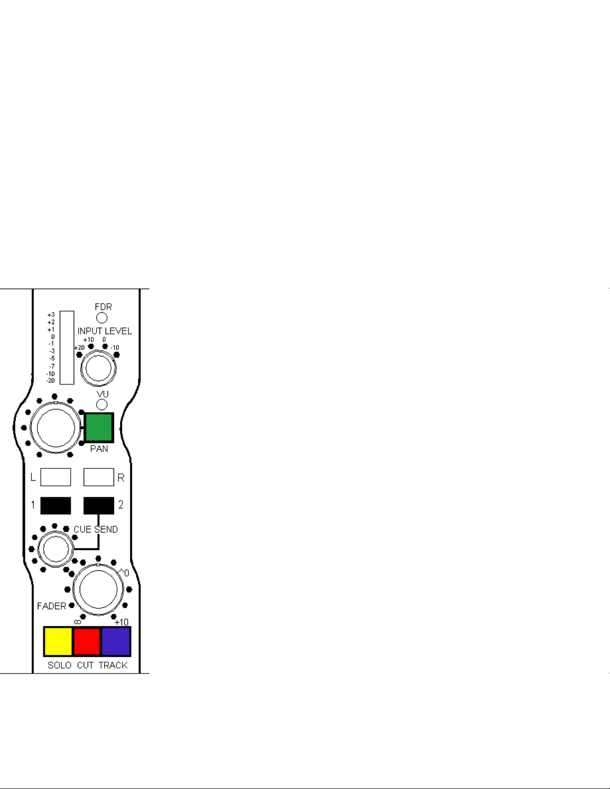
3. Channel functions
The GTM has 8 identical channel paths and can be extended by 8
channels at a time by plugging in additional 8 channel add-on
units.
It was always a feature of the design concepts of the GTM that it
should be easy to use and provide comprehensive information
about the signal. The channel has a stepped gain control with a
30dB range and steps of 10dB. Beside it is a fast acting LED VU
meter with a >23dB range. The LED's are three colors with –
20VU to –1VU in green, 0VU to +2VU in yellow, and +3VU in
red.
To select the appropriate channel sensitivity and maintain the best
headroom and noise figures, just rotate the input gain control
until the VU lights most LED’s but the red +3VU LED is only lit
occasionally (i.e. flashes momentarily) rather than on constantly.
If the red LED is on constantly, rotate the gain switch one click
anti-clockwise.
NB. A further 10dB gain is available at the fader.
The input channel has at least 20dB of headroom above the +3VU
(+7dBu) red LED so, provided the input gain is set at the optimal
position, the channel can accept signal levels of > +47dBu = over 55
volts of audio.
Page 2 of 18

The VU meter measures the signal level at the pre-fade insertion return point. This
means that, with nothing plugged into the insertion, it will measure input level and
with a device plugged into the insertion, it will measure the output level of that
device. Thus, in the event of the device being a equalizer with boost or compressor
with gain make up, the level can be adjusted either by the stepped gain control
(device input) or the fader (device output) and this will provide the user with a
convenient way of adjusting the channel level for the best and/or desired sound.
The channel can be assigned to four busses: - Post fade signals to the stereo output
busses (via a pan pot, if required) and a pre fade signal to the Cue/Aux busses via
a separate level control.
The ouput bus assign path now has a pan switch which, if not selected, allows
identical level signals to be sent to either or both output busses. When the pan
switch is selected, the zero insertion loss panpot is selected and the channel signal
can be positioned anywhere between full left and full right pan.
The Cue/Aux bus sends are pre fade and not affected by the pan pot. In the event
that the busses are used as an effects send, there is a stereo effects return path to
busses left and right in the GTM monitor section complete with a stereo level
control and mute switch.
At the bottom of each channel are three switches; the yellow switch is solo-inplace while the red switch is channel cut. Silent opto-isolator switching controls
all solo and muting functions. The blue button is the source selection switch
mentioned in section #2.
Pressing a channel solo button will mute all the other channels, lighting their red
mute switches to confirm this. Any channel can be released from muting by
pressing the associated solo switch and all solo switches need to be released for all
channels to function without muting.
There is a post fade channel output available at the male XLR on each channel as
well as simultaneously at the 25 pin “D” connector. As each channel has a
maximum gain of 20dB they can also be used as an interface with –10dBV
consumer equipment, bringing their signals up to pro-audio +4dBu levels.
Page 3 of 18
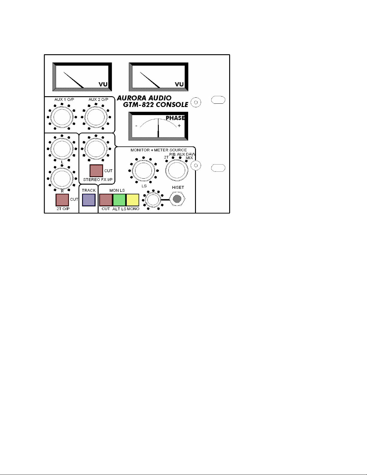
4. The Monitor/Meter section
The VU meters, phase
meter, monitor output and
headphone output all
follow the monitor source
selection switch.
The source switch selects
between 2T output (the
stereo mix), 2T playback
(the recorded mix), the
Aux outputs and the PT
Mix (that assumes that the
digital mix output is
assigned to channels #1 &
2).
By having the 2T output next to the 2T playback the user can switch between the
two for A – B comparisons.
There are two separate stereo monitor outputs (enabling the use of two pairs of
amplifiers and speakers) and the “ALT LS” switch toggles between the two
outputs.
A monitor “CUT” switch is also provided and also a “Mono” monitor switch that
puts the entire monitor (Monitor Speakers, Meters and Headphones) into mono
mode. It does not affect the stereo busses, only the monitor path.
The headphone output is independent of the monitor system and does not cut the
monitor outputs when a headphone is connected. As both monitor speakers and
headphones have independent level controls, the user can select the arrangement
best suited to them.
The headphone output socket is capable of driving any impedance from zero ohms
to infinity although impedances of less than around 22 ohms will be progressively
attenuated by the headphone protection resistors.
Page 4 of 18
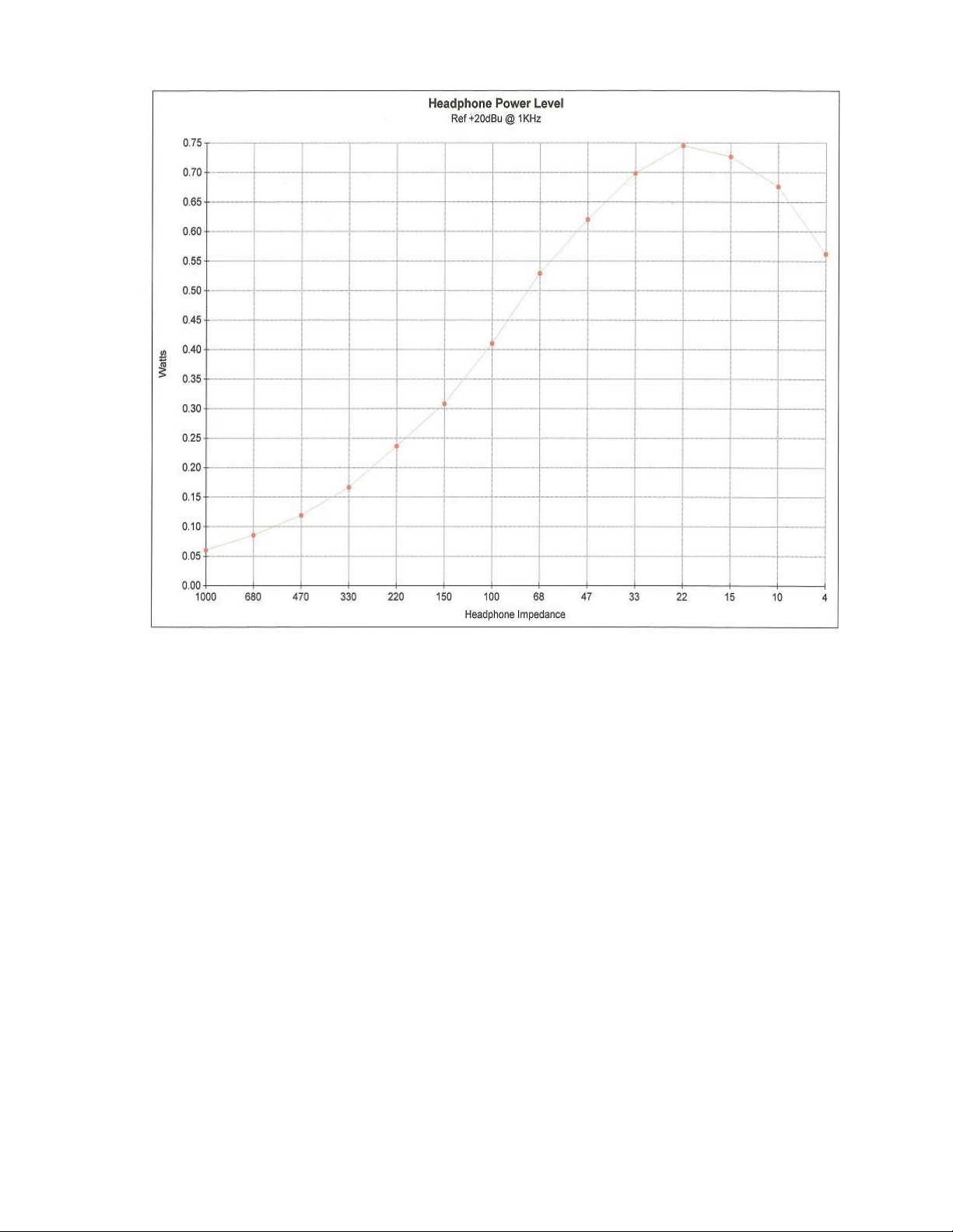
As can be seen in the chart above, the power dissipated into headphones depends
on their impedance.
For a given output voltage… in this case +20dBu = 7.75 volts at 1KHz… the
power is given by Voltage (squared) / load impedance. Thus 600 ohms headphones
will produce around 0.08 watts while 150 ohm headphones will produce 0.30
watts. The power available increases up to 0.75 watts at 22 ohms but then
diminishes to around 0.65 watt with consumer 8 ohm headphones and down to 0
(no output) at a zero ohm short circuit.
Even around 0.1 watt is pretty loud a signal with a pair of headphones clamped to
your ears but, in the case of drummers or musicians in a noisy environment, I’d
recommend using lower impedance headphones…
e.g. Sony MDR-7509 and MDR-V300 are 24 ohms
Fostex T40RP are 50 ohms
AKG K240 are 55 ohms
Sennheiser HD280 are 64 ohms
Page 5 of 18

In every case, the headphone level control should be set to zero before the
headphones are plugged in and then gradually increased to a
comfortable listening level. High levels can permanently damage your
hearing (and wreck your headphones)!
The Sifam VU meters are electronically buffered so that their internal rectifiers
do not affect the distortion specification of the GTM. The 0VU is +4dBu =
1.228 volts ac. All three analogue meters have internal LED illumination so no
bulb changing is required.
The phase meter provides constant confirmation of the mono compatibility of
the stereo mix signals. Out of phase components in the mix signal can spoil the
sound of the stereo image as well as causing cancellations in the mono
derivatives. In practice the meter will normally swing from center to about two
thirds full-scale deflection on the right. The deflection is proportional to the
phase difference between the two outputs. A hard left deflection indicates a
signal 180 degrees out of phase.
The phase meter circuit comprises of two very high gain pre-amplifiers that
“square” the input signal and drive a sum and difference network. Individual
output amplifiers buffer the two mixes and propel the center zero needle to left
or right of center depending on which amplifier has the stronger signal. If the
signal is comprised substantially of in-phase components the indicating needle
will be driven to the right (“+” region) and will ride on top of the signal,
fluctuating constantly as it checks phase at the varying input levels.
The phase meter will only measure the phase integrity of a stereo signal.
If one or both signal paths are not present the meter may indicate either
in or out of phase depending on whether the sum or difference meter
amplifier is the one fed with the arbitrary signal. Generally, unless there
is a signal on both outputs, one should not be concerned if the meter
reads a small degree of “―” reading or full “+” reading.
In the event that the phase meter indicates a significant anti-phase reading
(substantially to the left of center) then the user should use the channel solo and
mute buttons to locate which channel is carrying the error signal.
Try either muting individual channels or soloing pairs of channels until the
“bad phase” channel is identified.
Page 6 of 18
 Loading...