

Page 1
USERS GUIDE
Manual Number: 191125 | Firmware Rev: 1.6.0
www.auroramm.com
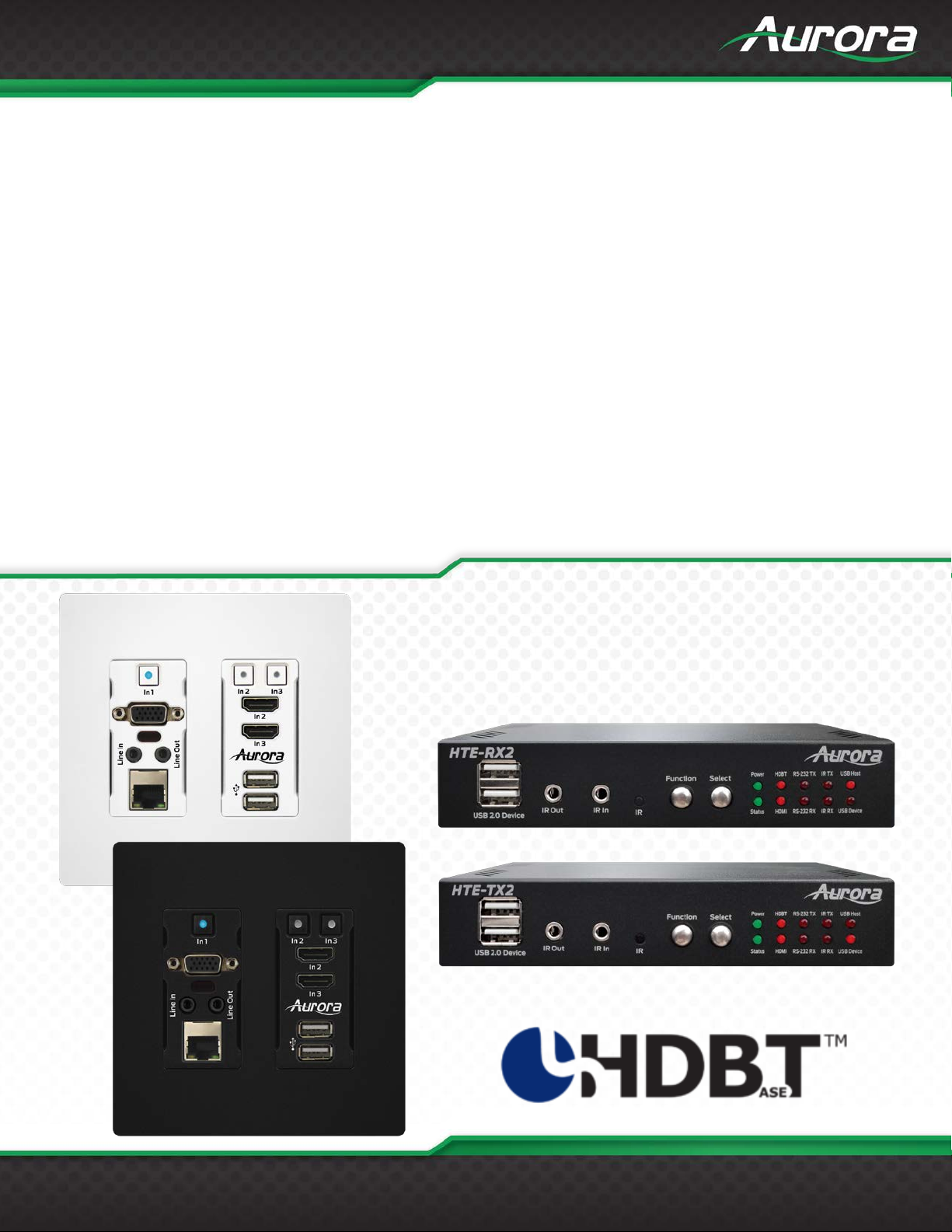
HT Series
HDBaseT Supercharged
HDMI 4K60 4:4:4 HDBaseT CAT Extenders
Page 2
USERS GUIDE
www.auroramm.com
ii
The lightning symb ol in the tr iangle is used to a lert you t o the presence of dan gerous voltag e inside the product
equipment attached to the product.
The exclamation po int in the triangle is use d to alert you to important operating and maintena nce instructions.
Be careful with electricity:
To prevent electric shock, be sure the electrical plug used on the product power cord
it from the power source.
Also follow these precautions:
ESD: Handle this unit with proper ESC care. Failure to do so can result in failure.
SAFETY INSTRUCTIONS
Please review the following safety precautions. If this is the first time using this model, then read this manual before
installing or using the prod uct. If the product is not functioning proper ly, please contact your local dealer or Aurora for
further instructions.
that may be sufficient to co nstitut e a ris k of elec tric s hock to anyo ne open ing th e c ase. It is also used t o indi cate
improper installation or handling of t he product th at could d amage the e lectrica l system in th e product or in o ther
Failure to follow these instructions could result in injury to you or damage to the product.
Power Outlet:
matches the electr ical o utle t used to s upply p ower to t he Aur ora pr oduc t. Us e th e power ada pter and p ower
connection cables designed for this unit.
Power Cord: Be sure the power cord is routed so that it will not be stepped on or pinched by heavy items.
Lightning: For protection from lig htning or w hen th e pr oduct is left u nattend ed for a long p eriod, disc onnec t
Ventilation: Do not block ventilation slots , if applic able, on t he product, or place any heavy object on t op of
FCC
This device complies with Part 15 of the FCC Rules. Operation is subject to the following two (2) conditions:
1. This device may not cause harmful interference.
2. This device must accept any interference received, including interference that may cause undesired operation.
Trademarks
All trademarks in this document are the properties of their respective owners.
it. Blocking airflow c ould c ause d amage. Arrang e co mponents so t hat air c an fl ow free ly. Ens ure that t her e
is adequate ventilat ion if th e product is placed i n a stand or c abinet. Put the pr oduct in a pr operly v entilated
area, away from direct sunlight or any source of heat.
Overheating: Avoid stacking the Aurora product on top of a hot component, such as a power amplifier.
Risk of Fire: Do not place unit on top of any easily combustible material, such as carpet or fabric.
Proper Connections: Be sure all cables and equipment are connected to the unit as described in this
manual.
Object Entry: To avoid electric shock, never stick anything in the slots on the case, or remove the cover.
Water Exposure: To reduce the risk of fire or electric shock, do not expose to rain or moisture.
Cleaning: Do not use liquid or aeroso l cleaners to clean t his unit. Always unplug the power to th e device
before cleaning.
Page 3

USERS GUIDE
www.auroramm.com
ii
TABLE OF CONTENTS
PACKAGE CONTENTS ......................................................................................................................................................... 4
OPTIONAL ACCESSORIES .................................................................................................................................................. 5
INTRODUCTION ..................................................................................................................................................................... 6
About ................................................................................................................................................................................... 6
Features .............................................................................................................................................................................. 6
HTE-TX2 Front & Rear ........................................................................................................................................................ 7
HTE-RX2 Front & Rear ....................................................................................................................................................... 9
HTW-2 Front & Rear ......................................................................................................................................................... 11
OPERATION ......................................................................................................................................................................... 13
Source Selection ............................................................................................................................................................... 13
Auto Sense ........................................................................................................................................................................ 13
EDID Handling................................................................................................................................................................... 13
Factory Reset .................................................................................................................................................................... 13
APPLICATIONS.................................................................................................................................................................... 14
Example 1 Typical HTW-2 Transmitter to HTE-RX2 Receiver ......................................................................................... 14
Example 2 DXB-8 Button Wall Control to HTW-2 ............................................................................................................. 15
Control Protocols ................................................................................................................................................................ 16
RS-232 Commands ........................................................................................................................................................... 16
Audio Command Usage Detail .......................................................................................................................................... 21
Serial Query Commands ................................................................................................................................................... 25
RPC Commands ............................................................................................................................................................... 28
ReAX TCP Commands ..................................................................................................................................................... 36
IR EXTENDERS .................................................................................................................................................................... 45
IR Connections .................................................................................................................................................................. 45
IR Jack Pinout ................................................................................................................................................................... 45
CONNECTOR PIN DEFINITION ........................................................................................................................................... 46
HDMI ................................................................................................................................................................................. 46
VGA ................................................................................................................................................................................... 46
CAT5e/6/7 ......................................................................................................................................................................... 47
APPENDIX 1 ......................................................................................................................................................................... 48
Troubleshooting ................................................................................................................................................................ 48
APPENDIX 2 Firmware Update......................................................................................................................................... 49
APPENDIX 3 VGA Supported Timing .............................................................................................................................. 51
APPENDIX 4 ......................................................................................................................................................................... 52
Page 4

USERS GUIDE
www.auroramm.com
iii
Technical Specifications .................................................................................................................................................... 52
APPENDIX 5 ......................................................................................................................................................................... 56
Cabling .............................................................................................................................................................................. 56
APPENDIX 6 ......................................................................................................................................................................... 57
Warranty ............................................................................................................................................................................ 57
Page 5
USERS GUIDE
www.auroramm.com
4
PACKAGE CONTENTS
Please make sure the following items are included within your package. Contact your dealer if any items are
missing or damaged.
HTE-RX2
HTE-RX2 x 1
Wall/Desk Mount Ears with Screws x 4
HTE-TX2
HTE-TX2 x 1
Wall/Desk Mount Ears with Screws x 4
HTW-2
HTW-2 x 1 (-W for white, -B for black)
Note: Some 2 gang electrical boxes or mud rings have curved or beveled corners that may prevent the
HTW-2from properly fitting. Make certain to use a brand that fits the full dimensions listed in the
specification section.
Optional Accessories
PS0094-2 48V DC Wall Power Supply
PS0081-1 48v DC Desktop PoE+ Injector
*Note: Go to www.auroramm.com
for latest manual and firmware.
Page 6
USERS GUIDE
www.auroramm.com
5
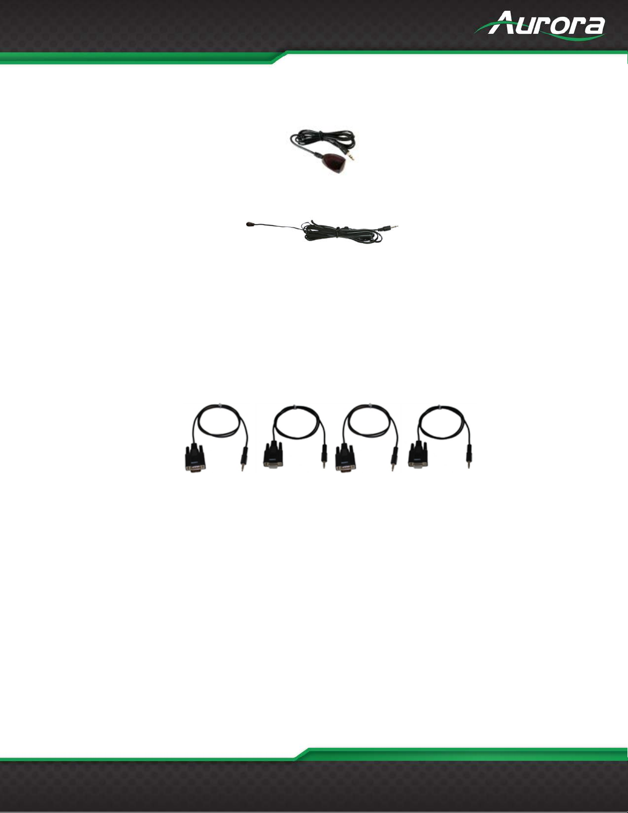
OPTIONAL ACCESSORIES
IR Receiver CA0026-1
IR Emitter CA0061-1
RS-232 Adaptor CA0052-F2T3R
(3.5mm TRS to FEMALE DB89 2-TX 3-RX)
RS-232 Adaptor CA0052-F3T2R
(3.5mm TRS to FEMALE DB89 3-TX 3-RX)
RS-232 Adaptor CA0052-M2T3R
(3.5mm TRS to MALE DB9 2-TX 3-RX)
RS-232 Adaptor CA0052-M3T2R
(3.5mm TRS to MALE DB9 3-TX 2-RX)
Page 7

USERS GUIDE
www.auroramm.com
6
• 4K60 4:4:4 18Gbps
• HDCP 1.4/2.2
• 100m (330ft) with Unshielded Cable
• HDMI® 2.0/HDCP 2.2
• Audio DSP & Dante™/AES67 Options 2 or 8 Channel
• ARC Audio Return Channel and ARC into Dante/AES67 Industry First!
• Operate & Power both TX & RX from a single PoE Switch Port
• Auto Switching
• Two HDMI® Inputs & One VGA Input (HTW-2)
• Two HDMI® Outputs (HTE-RX2)
• 1G Local LAN Ports, 10/100 over the HDBaseT Connection
• USB 2.0 Device/Host with Selectable Direction
• IP Port Expansion Control, RS-232 & IR Control
• ReAX Control Option
INTRODUCTION
About
The HTW-2 transmitter wall plate, HTE-TX2 transmitter, and HTE-RX2 HDBaseT 2.0 products are part of
Aurora’s HT Series capable extending 4K60 4:4:4 & HDR (18Gbps) 100m (330′) with unshielded cable. The 2gang low depth Decora™ wall plate is not only stylish but extremely functional with 3 inputs (1 VGA & 2 HDMI).
All units have directional USB to allow a user to choose which side the host (PC) vs the device (peripheral) will
be located. Built in IP port expansion allows any 3rd party control system to send commands directly to the unit
for source switching, RS-232, and IR control. Aurora is the only product to allow a single PoE port power both
the TX and RX at the same time with no wall supplies required for a very clean installation. For easier
integration into an audio system, the HT Series is the only HDBaseT product to have optional Dante/AES67 up
to 8 channels for surround sound. The Aurora HT Series re-invents the capabilities of HDBaseT beyond the
typical point to point making it the ultimate HDBaseT integrator solution.
Features
• HDR (high Dynamic Range)
• Two HDMI® Inputs (HTE-TX2)
*Note: Refer to Technical Specifications section.
Warning: Do not plug RJ-45 HDBaseT output to non-HDBaseT complaint devices or damage may occur
to either product.
Page 8
USERS GUIDE
www.auroramm.com
7
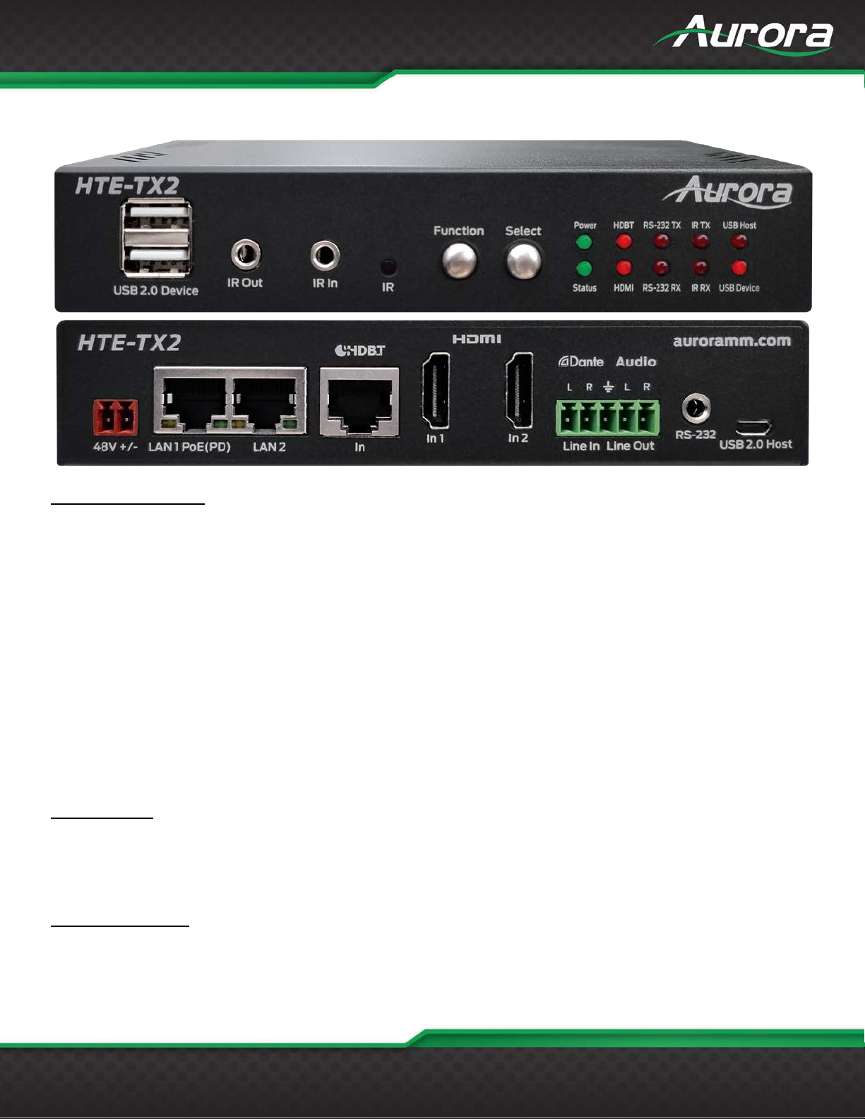
HTE-TX2 Front & Rear
Front LED Indicators
• POWER: Lights green when power is present.
• STATUS: Will blink s teady if unit is working properly.
• HDBT: Lights when HDBaseT RJ-45 has proper connection between an RX/TX pair. Blinks when in
sleep mode.
• HDMI: Will light solid if HDMI is plugged in on both RX/TX and HDCP is present. If no HDCP, LED will
blink.
• TX: RS-232 Transmit. Blinking rate and intensity will vary with baud rate.
• RX: RS-232 Receive. Blinking rate and intensity will vary with baud rate.
• IR TX: Blinks when emitting IR to device from IR Out Port.
• IR RX: Blinks when receiving IR from IR RX port.
• USB Host: When lit the rear micro USB port should be used and connected to the PC.
• USB Device: When lit the Front Dual USB ports should be used and connected to the peripherals like
keyboard, mouse, memory stick, camera, etc.
Front Buttons
• Function: Press to scroll between various capabilities that can be modified with the select button.
• Select: Allows the changing of features based on the function mode selected.
Front Connections
• Dual USB 2.0: USB 2.0 connectors. Units USB Device LED must be lit for it to function properly with
remote end. Can also be used to charge devices.
Page 9
USERS GUIDE
www.auroramm.com
8
• IR OUT: Plug the IR emitter into this port and affix onto the device where its IR window is located.
• IR IN: Plug the IR receiver into this port. The front built in IR receiver will no longer work once the
external receiver is plugged in. Note this port should be used with Aurora IR receiver model as other
brands may not follow the correct pinout or voltage.
• IR: IR receiver capable of 32KHz to 60KHz range.
Rear Connections
• 48V DC: Power connector for 25-watt 48VDC power su p ply (PS0094-2-S).
Note: Only 1 supply is required to power both units. Either side can send power to the other unit.
Note: If LAN PoE is utilized the 48VDC supply is not required.
• RS-232: Connect RS-232 device up to 115k baud.
• LAN1/2: 1Gbps LAN connection. LAN1 can use PoE or PoE+ from a PoE switch to power both the RX
and TX units.
• HDBaseT: Connect CAT 5e/6/7 cable. Shielded cable is not necessary unless the environment has a
lot of electrically noise.
• HDMI Input 1/2: Plug HDMI cable f rom source device like a Blu-ray player. Sour ce can be selected
from RS-232, Ethernet, Auto Sense Mode, or front buttons.
Note: The HDMI cable should be rated for the bandwidth you are using.
• Audio Line In/Out: Euro Style connector for stereo line in and line out.
• USB 2.0 Host: Micro USB 2.0 Connector for connection to PC. Unit must be set for Host mode for it to
properly operate.
*Note: Some POE switches do not supply the full 15.4watts per port. Verify the total power rating of the
switch. It should be at least 15.4W x (number of ports) and ideally 25.4W (PoE+) per port if USB
peripherals are to be utilized.
Option Port
Inside the unit there is an option card connector for the Dante 2ch or 8ch option or the ReAX control system
option. Only one of the cards can be installed into a unit. To access the port, power off unit and the 4 screws (2
on each side) must be removed. Take the cover off and insert the card in the proper orientation as indicated on
the circuit board. Put cover back on and apply power. Don’t forget to note the MAC address of the card to
identify which unit it is in.
Page 10
USERS GUIDE
www.auroramm.com
9
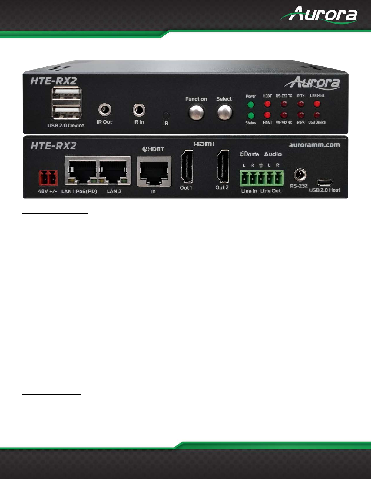
HTE-RX2 Front & Rear
Front LED Indicators
• POWER: Lights green when power is present.
• STATUS: Will blink s teady if unit is working properly.
• HDBT: Lights when HDBaseT RJ-45 has proper connection between an RX/TX pair. Blinks when in
sleep mode.
• HDMI: Will light solid if HDM I is plugg ed in on both RX/ TX and HDCP is pre sent. If no HDCP, LED will
blink.
• TX: RS-232 Transmit. Blinking rate and intensity will vary with baud rate.
• RX: RS-232 Receive. Blinking rate and intensity will vary with baud rate.
• IR TX: Blinks when emitting IR to device from IR Out Port.
• IR RX: Blinks when receiving IR from IR RX port.
• USB Host: When lit the rear micro USB port should be used and connected to the PC.
• USB Device: When lit the Front Dual USB ports should be used and connected to the peripherals like
keyboard, mouse, memory stick, camera, etc.
Front Buttons
• Function: Press to scroll between various capabilities that can be modified with the select button.
• Select: Allows the changing of features based on the function mode selected.
Front Connections
• Dual USB 2.0: USB 2.0 connectors. Units USB Device LED must be lit for it to function properly with
remote end. Can also be used to charge devices.
Page 11
USERS GUIDE
www.auroramm.com
10
• IR OUT: Plug the IR emitter into this port and affix onto the device where its IR window is located.
• IR IN: Plug the IR receiver into this port. The front built in IR receiver will no longer work once the
external receiver is plugged in. Note this port should be used with Aurora IR receiver model as other
brands may not follow the correct pinout or voltage.
• IR: IR receiver capable of 32KHz to 60KHz range.
Rear Connections
• 48V DC: Power connector for 25-watt 48VDC power supply (PS0094-2-S).
Note: Only 1 supply is required to power both units. Either side can send power to the other unit.
Note: If LAN PoE is utilized the 48VDC supply is not required.
• RS-232: Connect RS-232 device up to 115k baud.
• LAN1/2: 1Gbps LAN connection. LAN1 can use PoE or PoE+ from a PoE switch to power both the RX
and TX units.
• HDBaseT: Connect CAT 5e/6/7 cable. Shielded cable is not necessary unless the environment has a
lot of electrically noise.
• HDMI Output 1/2: Plug HDMI cable from device like a LCD monitor. Both outputs will show the same
signal. It is designed for loop through. Note: The HDMI cable should be rated for the bandwidth you
are using.
• Audio Line In/Out: Euro Style connector for stereo line in and line out.
• USB 2.0 Host: Micro USB 2.0 Connector for connection to PC. Unit must be set for Host mode for it to
properly operate.
*Note: Some POE switches do not supply the full 15.4watts per port. Verify the total power rating of the
switch. It should be at least 15.4W x (number of ports) and ideally 25.4W (PoE+) per port if USB
peripherals are to be utilized.
Option Port
Inside the unit there is an option card connector for the Dante/AES67 2ch or 8ch option or the ReAX control
system option. Only one of the cards can be installed into a unit. To access the port, power off unit and the 4
screws (2 on each side) must be removed. Take the cover off and insert the card in the proper orientation as
indicated on the circuit board. Put cover back on and apply power. Don’t forget to note the MAC address of the
card to identify which unit it is in.
Page 12
USERS GUIDE
www.auroramm.com
11
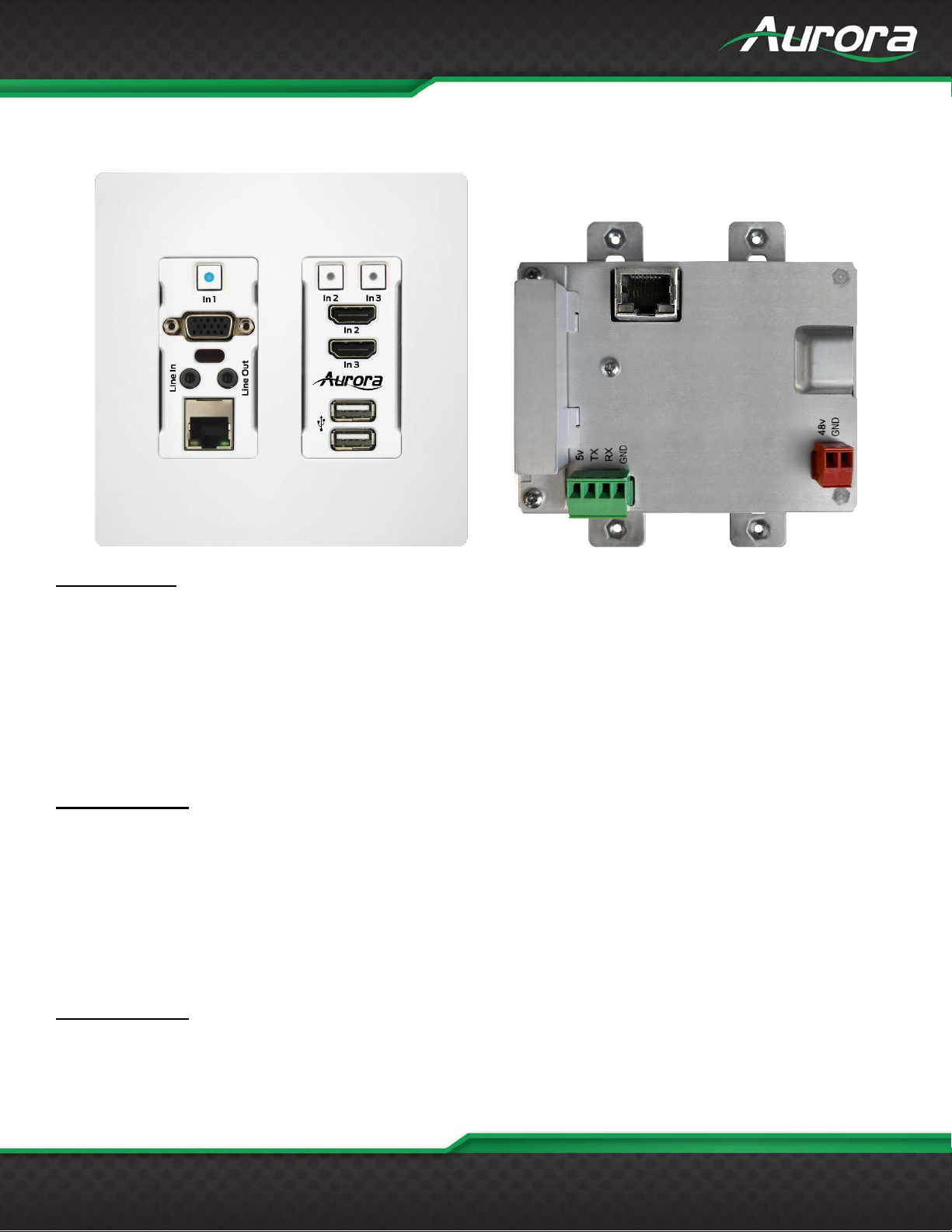
HTW-2 Front & Rear
Front Left Side
• In1 Button: The blue backlit button will select the VGA.
• DB15 VGA Connector: VGA up to 1080p can be input. The VGA will be converted to HDMI and sent
HDBaseT to the receiver unit. Note: See appendix for pin out information.
• Line In: Audio input for the VGA connector sources to be embedded in HDMI
• Line Out: Audio output for ARC, Loop out, or Dante option.
• RJ-45 LAN Connector: 1Gbps locally and 10/100 LAN via HDBaseT receiver unit.
• IR Window: Receiver for IR signals from remote ranging between 32KHz to 60KHz.
Front Right Side
• In2 and In3 Buttons: The buttons will select between HDMI In2 or HDMI In3 and will light accordingly.
• HDMI Connectors: Use with HDMI 2.0 or DVI sources like Blu-ray players, laptops, etc.
• Dual USB 2.0 Connectors: USB 2.0 480Mbps and supplies up to 1A of power between both ports.
Great for charging port of USB devices like phones and certain tablets. When in USB Host Mode the
bottom port is for PC (Type A to Type A cable is supplied) and upper port is charging only. When in
Device mode both ports work on a hub for mouse, keyboard, camera, memory stick, etc.
Rear Connections
• 48V DC: Power connector for 48V DC power supply. If remote device can supply power over HDBaseT
then the local power is not required. Currently all receiver types from Aurora supply power over the
Page 13
USERS GUIDE
www.auroramm.com
12
HDBaseT.
• HDBaseT: Connect CAT 5e/6/7 cable. Shielded cable is not necessary unless the environment has a lot of
electrically nois e.
• RS-232: Connect RS-232 device up to 115k baud. Note there is a 5v line as it is designed to power the
DXB-8 8 button wall plate.
Note: Some 2 gang electrical boxes or mud rings have curved or beveled corners that may
prevent the HTW-2 from properly fitting. Make certain to use a brand that fits the full
dimensions listed in the specification section.
Note: Only 1 supply or PoE is required to power both units from RX which can send power to the wall
unit.
Note: If LAN POE is utilized at the RX the 48VDC supply is not required.
Option Port
On the rear of the unit there is an option card connector for the Dante/AES67 2ch or 8ch option or the ReAX
control system option. Only one of the cards can be installed into a unit. To access the port, power off unit and
the 2 screws (1 on each side) must be removed. Take the cover off and insert the card in the proper orientation
as indicated on the circuit board. Put cover back on and apply power. Don’t forget to note the MAC address of
the card to identify which unit it is in.
Page 14

USERS GUIDE
www.auroramm.com
13
OPERATION
Source Selection
The HT Series can change between the various sources via front buttons, RS-232, LAN, and Auto-Sense.
Once a source is selected the display will lock within a few seconds. The time to lock depends on the display
but typical time can be from 3-5 seconds. Keep in mind the HTW-2 series does not scale so what comes in is
what will go back out for both the VGA and the HDMI. Most modern displays have scalers and the HT Series
can handle resolutions up to 4K60 4:4:4.
Auto Sense
The HT Series has Auto-Sense capability. Auto-Sense will automatically switch to the last HDMI or VGA input
connected provided a hot-plug is provided from the source device. The HTW-2 factory default is enabled but
can be disabled and saved in non-volatile memory via RS-232 command. In addition, the front button selection
or RS-232 control will allow the HT Series to switch away until another new input is detected. For example, if a
user has a laptop plugged into the VGA port and then connects a Blu-ray
automatically switch to the HDMI input. If after that the laptop is disconnected or signal is removed with
function keys and reconnected the HTW-2 will switch back to the laptop. If an RS-232 command is received to
switch to the opposite input the unit will do so as well. Whenever a source is changed the LED on the button
will follow and the RS-232 ports will send a response string to let a remote device know that a change has
occurred.
®
player to the HDMI, the HTW-2 will
EDID Handling
The HDMI port will retrieve the EDID from the destination device (ex. Projector, LCD, Matrix, etc.) via the
HDBaseT connection to the receiver unit. The VGA port will use an internal EDID specific to the capabilities of
the HTW-2 VGA port with 1080p being the recommended default.
Factory Reset
Holding both buttons for 5 seconds will restore factory defaults. This will be confirmed by both buttons turning
cyan. Keep in mind all stored settings into the non-volatile memory will revert to the factory defaults of each
function accordingly.
Page 15
USERS GUIDE
www.auroramm.com
14
APPLICATIONS
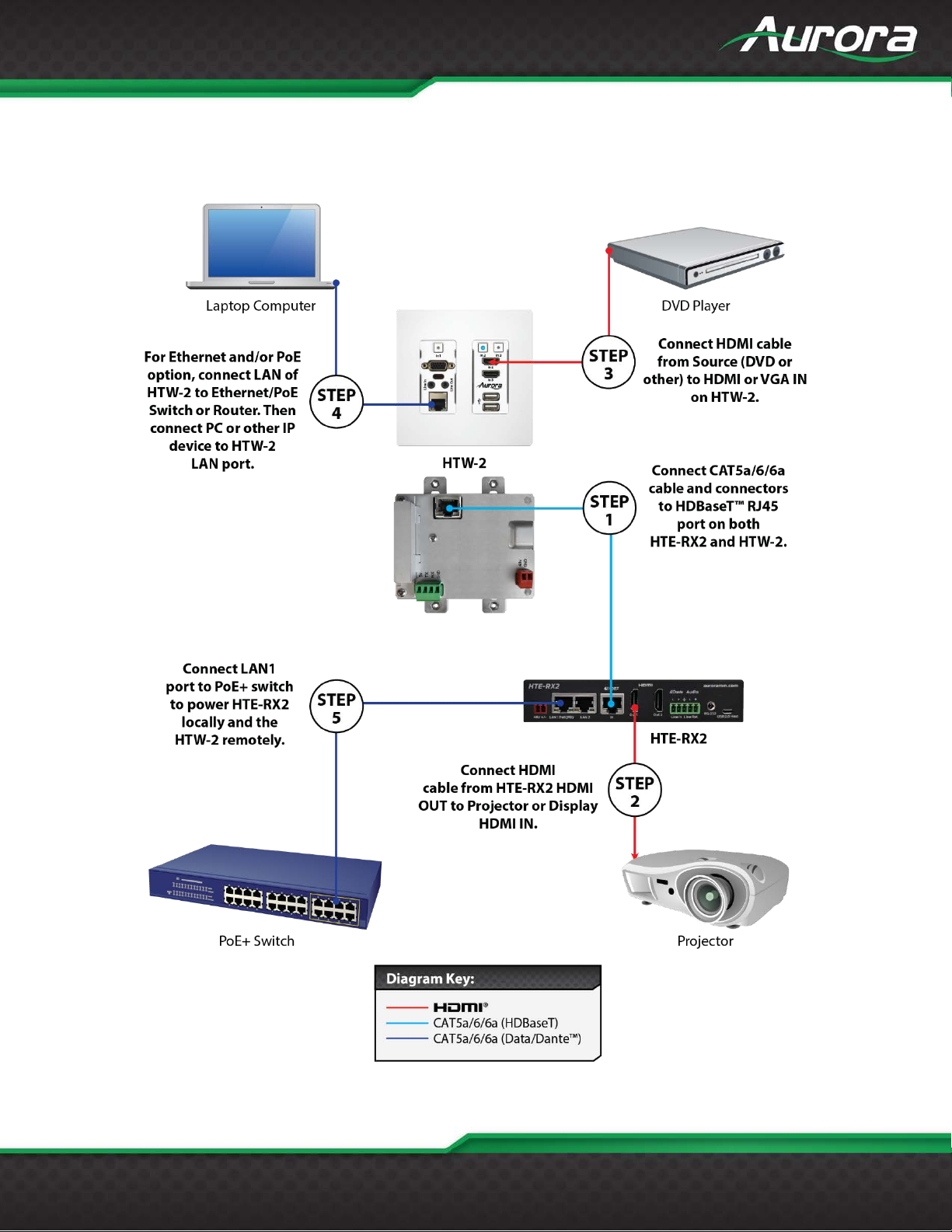
Example 1 Typical HTW-2 Transmitter to HTE-RX2 Receiver
Page 16
USERS GUIDE
www.auroramm.com
15
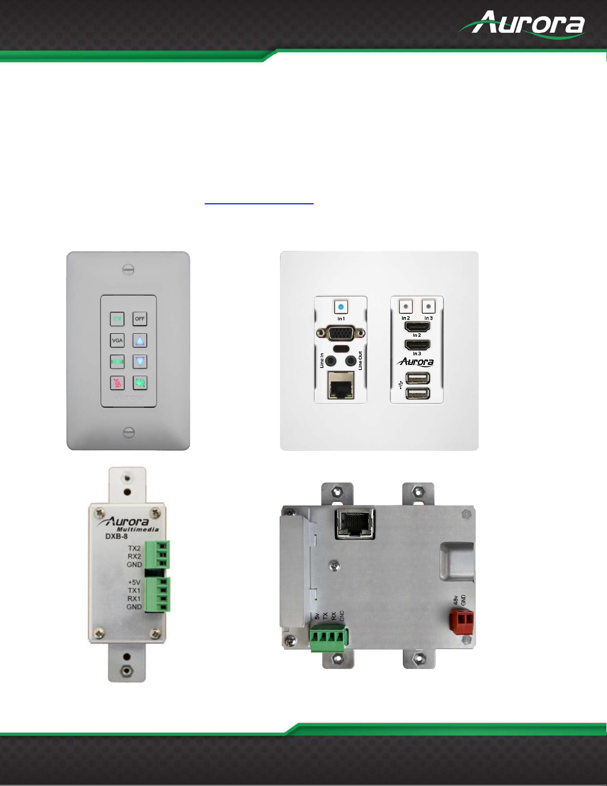
Example 2 DXB-8 Button Wall Control to HTW-2
DXB-8 wall controller connected to the HTW-2 Series. The DXB-8 serial port will connect and draw
power from the HTW-2 via the 4 pin RS-232 connection. Any serial command can be programmed
into the DXB-8 at any baud rate and sent through the HTW-2 to the HTE-RX receiver. This allows not
only the switching of the HTW-2 to be controlled but the remote display device as well. Make certain
the baud rates are set the same on the HTW-2 and the DXB-8. More information on the DXB-8 can
be found on the Aurora website www.auroramm.com
Page 17
USERS GUIDE
www.auroramm.com
16
Reboots the i.mx RT processor.
Response: ~**REBOOT
Enable the bootloader update.
Response: ~**BOOTUPDATE
Enter firmware update mode.
Response: ~**WSUPDATE
xxx = 000 – 255
Response: ~**IP192.168.001.150<cr>
xxx = 000 – 255
Response: ~**GW192.168.001.001<cr>
xxx = 000 – 255
Response: ~**SM255.255.255.000<cr>
X = 0 or 1
Response: ~**DEBUGWS1<cr>
Debug Web
Video
X = 0 or 1
0 = Off
Control Protocols
RS-232 Commands
! - Command, ? - Query, ~ Response
<CR> = 0x0D Hex / 13 Decimal
The serial command can be issued by the user via the local serial port of the device. !** is the command
header used to specify the device. If !** is given as !20, then the command is intended for the TX/HTW
devices. If the header !** is given as !30, then the command is intended for !30.
These commands are mainly used to control/configure the device. To query the device status/ configuration,
refer Serial Query Commands.
If both TX and RX devices are connected, then the user can send serial commands from TX to RX by providing
the serial header as !30. The TX will ignore the command and send it to the remote device. The remote RX will
process the command and send the response back to the TX. The TX will output this response to the user.
Similar is the case when !20 commands are issued to RX.
Note: By default, the configuration of the local serial port is Baud = 115200, Data bits = 8, Parity = None, Stop
bits = 1.
Serial Command String Format Information
Reboot !**REBOOT
Bootloader Update !**BOOTUPDATE
Firmware Update. !**WSUPDATE
Set Web Server IP Address !**IPxxx:xxx:xxx:xxx<cr>
Set We b Server G ateway !**GWxxx:xxx:xxx:xxx<cr>
Set Web Server Subnet Mask !**SMxxx:xxx:xxx:xxx<cr>
Debug Web Server Processor !**DEBUGWSx<cr>
Example: !**IP192.168.001.150<cr>
Example: !**GW192.168.001.001<cr>
Example: !**SM255.255.255.000<cr>
0 = Off
1 = On
Example: !**DEBUGWS1
!**DEBUGMPx<cr>
Page 18

USERS GUIDE
www.auroramm.com
17
Processor
1 = On
Response: ~**DEBUGMP1<cr>
b = Baud Rate 1200, 2400, 4800, 9600,
Response: ~**SP1,115200,8,N,1<cr>
X = 0 or 1
Response: ~**LOCK1<cr>
X = 0,1 or 2.
Response: ~**DHCP1<cr>
X = 0 or 1
~**IR_CARRIER_STRIP1<cr>
X = 0 or 1
Response: ~**IR_INVERSE1<cr>
IR carrier removal at transmitter
Removes the carrier in the IR signal from
enabling at TX disables at RX and vice
Serial Command String Format Information
Serial Port
Settings for
external port
Front Panel Lock !**LOCKx<cr>
IP mode change. !**DHCPx<cr>
!**SP1,b,d,p,s<cr>
Example: !**DEBUGMP1
19200, 38400, 57600, 115200
d = Data Size 7 or 8
p = Parity N, E, O (None, Even, Odd)
s = Stop Bits 1 or 2
Example: !**SP1,115200,8,N,1<cr>
0 = Lock is disabled.
1 = Lock is enabled (Front buttons do
not work).
Example: !**LOCK1<cr>
0 - DHCP mode.
1 - Static IP mode.
2 - AutoIP mode.
Example: !**DHCP1<cr>
IR carrier removal !**IR_CARRIER_STRIPx<cr>
IR carrier inverse !**IR_INVERSEx<cr>
side.
!**VS_CARRIER_STRIPx<cr>
1 - Removes carrier.
0 - Disabled.
Example: !**IR_CARRIER_STRIP1<cr>
Response:
1 - Inverts carrier.
0 - Disabled.
Example: !**IR_INVERSE1<cr>
the IR Remote and outputs to HDBT.
X = 0 or 1
1 - Removes carrier.
0 - Disabled.
Example: !**VS_CARRIER_STRIP1<cr>
Response:
~**VS_CARRIER_STRIP1<cr>
Note: A device can have IR carrier
removal enabled either at transmitter or
at the receiver side. But not both. So,
Page 19
USERS GUIDE
www.auroramm.com
18
versa.
Inverts the IR signal from the IR Remote
Response: ~**VS_INVERSE1<cr>
Input From
!**AUD1,4
X = 0 or 1 or 2
board.
Defaults the file system. After defaulting,
Response: ~**FILESYS_DFLT<cr>
Factory defaults the HTE/HTW to
Serial Command String Format Information
IR carrier inverse at transmitter
side.
Audio Routing
(In depth explanation at end of
command table)
!**VS_INVERSEx<cr>
!**AUD<input_from>,<output_to>
and outputs to HDBT.
X = 0 or 1
1 - Inverts carrier.
0 - Disabled.
Note: It is enabled by default.
Example: !**VS_INVERSE1<cr>
Line in - 1, Dante - 2, HDMI (TX Unit) 3, Remote Audio (RX Unit) - 4, HDBT
Extracted Video - 5, ARC (RX Unit) - 6
None - 0
Output To
Lineout - 1, Dante - 2, HDMI - 3,
Remote Audio- 4
Audio insertion will work only in HTE TX
Example usages
Line in to Line out
!**AUD1,1
Line in to Dante
!**AUD1,2
Line in to HDMI(Only in TX)
!**AUD1,3
Line in to Remote Audio
Video Routing !20VID_SRCx<cr>
Format the File system !**FILESYS_DFLT<cr>
Factory default HTE/HTW. !**WPROC_DFLT<cr>
0 and 1 - HDMI.
2 - VGA (Only for HTE – wall plate).
Example: !20VID_SRC1<cr>
Response: ~20VID_SRC1<cr>
Note: Only for HTE-TX and HTW
the device will reboot with /IR and
/wwwpub directories present.
Example: !**FILESYS_DFLT<cr>
default configuration.
Page 20

USERS GUIDE
www.auroramm.com
19
The default configuration is:
Response: ~**WPROC_DFLT<cr>
Change USB mode.
it will be stopped for a moment.
~**LINEIN_VOL<0-100><cr>
Eg: !**LINEIN_VOL88<cr>
~**LINEOUT_VOL<0-100><cr>
~**LINEOUT_VOL88<cr>
Mutes the Linein
Response: ~**LINEIN_MUTE<cr>
Mutes the Line out
Response: ~**LINEOUT_MUTE<cr>
Simulates a button push
Response: ~**BTN_PUSH1<cr>
Simulates a button release
Response: ~**BTN_REL1<cr>
button_num>,<press_m
Button_num: 1,2, 3
Eg: !**BTN_LED1,p,r
Serial Command String Format Information
USB mode change. !**USBx<cr>
IP mode = Auto-IP
Static ip = 192.168.1.10
Static netmask = 255.255.255.0
Static gw = 192.168.1.1
Serial conf = 115200-8n1
Password = admin
Button Lock = Disabled
IR Carrier removal = Disabled
IR Carrier reversal = Disabled
Port Processing mode = Extender mode
USB mode (TX/HTW) = Host
USB mode (RX) = Device
Example: !**WPROC_DFLT<cr>
X = 0 or 1.
0 - Host.
1 - Device.
Example: !**USB1<cr>
Response: ~**USB1<cr>
Note:
If a video stream is in progress, then
Line in volume !**LINEIN_VOL<0-100><cr>
Line Out volume !**LINEOUT_VOL<0-100><cr>
Line in Mute !**LINEIN_MUTE<cr>
Line out Mute !**LINEOUT_MUTE<cr>
Button Push !**BTN_PUSH<button_num><cr>
Button release !**BTN_REL<button_num><cr>
Set button led
!**BTN_LED<
ode>,<color><cr>
Eg: !**LINEOUT_VOL88<cr>
Response:
Eg; !**LINEIN_MUTE<cr>
Eg; !**LINEOUT_MUTE<cr>
Eg: !**BTN_PUSH1<cr>
!**BTN_REL1<cr>
press_mode: press, release
color: r,g,b,y,c,m,w, n
corresponding to red, green, blue,
yellow, cyan, magenta, white, none
Page 21
USERS GUIDE
www.auroramm.com
20
Response: ~**BTN_LED1,p,r
Button_num: 1,2, 3
~**SET_BTN_MODE1,p,1
Button_num: 1,2, 3
~**CLR_BTN_MODE1,p,1
Button num 1/2/3(wallplate)
!20BTN_PARAM1,P,S,abc123,1
Filename: name of the ir file
~**SEND_IR
Reads the string stored in the internal
~**SERIAL_READ<port>:<string>
Clears the serial read buffer
!**SERIAL_CLR_BUFFER
Serial Command String Format Information
Set button mode
Clear button mode
Set Button Parameters
!**SET_BTN_MODE<button_num>,
<press_mode>,<button_mode><cr>
!**CLR_BTN_MODE<button_num>,
<press_mode>,<button_mode><
cr>
!**BTN_PARAM<button_num>,<pre
ss_mode>,<command_mode>,<co
mmand_string>,<port/ip_addr>,<teln
et_port><cr>
press_mode: press, release
button_mode: 1,2,3 corresponding to
default, serial, tcp
Eg: !**SET_BTN_MODE1,p,1
Response:
press_mode : press, release
button_mode: 1,2,3 corresponding to
default, serial, tcp
Eg: !**CLR_BTN_MODE1,p,1
Response:
PressMode: p(press) or (release)
Command_mode:
Button num 1/2/3(wallplate)
PressMode: p(press) or (release)
Command_mode: t(tcp)/s(serial)
Command_string: string to be send on
button press (500 char max)
Port: (1/2) serial port in case of serial
mode
Ip: ip address in case of tcp
Telnet port: in case of TCP mode
Eg:
!20BTN_PARAM1,P,T,abc123,192.168.1
.10,6000
Send IR
Read Serial !**SERIAL_READ<port><cr>
Clear serial Buffer
!**SEND_IR<filename>,<Command
name><cr>
!**SERIAL_CLR_BUFFER<port><cr
>
command name: Name of the command
inside the ir file
Eg:
!**SEND_IRsony.wir,ON
Response
buffer
Applicable only in Manual Method of
serial port processing
Port<1 or 2>
Eg:
!**SERIAL_READ<cr>
Response:
Applicable only in Serial port processing
manual method.
Eg:
Page 22
USERS GUIDE
www.auroramm.com
21
Response:
~**SERIAL_CLR_BUFFER1
Input
Meaning
1
Line in
2
Dante
3 (Applicable only in TX)
HDMI audio from selected HDMI port
4
Independent Remote Audio (Audio that is coming from the remote device(rx/tx) via
independent audio stream)
5 (Applicable only in RX)
Audio extracted from HDBT stream video at RX
6 (Applicable only in RX)
Arc audio at RX
Output
Meaning
1
Lineout
2
Dante
3 (Applicable only in TX)
Audio that goes along with the video (HDBT video stream)
4
Independent Remote Audio (Audio that should reach the remote device(tx/rx) via
independent audio stream)
Serial Command String Format Information
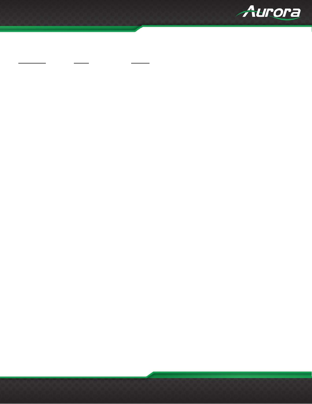
Table 1. Serial commands
Audio Command Usage Detail
HT Series has two independent audio streams.
1. Audio that is embedded in the video.
2. Independent audio stream.
There are 4 audio inputs in HTW-2/HTE-TX, 6 audio inputs for HTE-RX and 4 audio outputs for both TX and
RX.
Page 23
USERS GUIDE
www.auroramm.com
22
Below are the commands that can be used for routing audio for some common scenarios.
Command Input Output
!20AUD 1(line in) 1(line out)
!30AUD 2(dante) 2(dante)
3(hdmi) 3(stream_audio)
4(remote_audio) 4(remote_audio)
5(arc at Rx)
!**AUD1,1 - Line in to Lineout
!**AUD1,2 - Line in to Dante
!**AUD1,3 – Line in to Stream Audio ( only applicable in tx)
!**AUD1,4 – Line in to Remote Audio
!**AUD2,1 - Dante to Lineout
!**AUD2,2 - Dan te to Dant e
!**AUD2,3 - Dante to Stream Audio ( only applicable in tx)
!**AUD2,4 - Dante to Remote Audio
Only applicable in Tx
!**AUD3,1 - HDMI audio to Lineout
!**AUD3,2 - HDMI audio to Dante
!**AUD3,3 - HDMI audio to Stream Audio ( only applicable in tx) - Default case when the device is factory
defaulted for HDMI sources
!**AUD3,4 - HDMI audio to Remote Audio
!**AUD4,1 - Remote audio to Lineout
!**AUD4,2 - Remote audio to Dante
!**AUD4,3 - Remote audio to Stream Audio (only applicable in tx)
!**AUD4,4 - Remote audio to Remote Audio
Only applicable in RX
!**AUD5,1 - Arc to Lineout
!**AUD5,2 - Arc to Dante
!**AUD5,4 - Arc to Remot e Audio
Page 24

USERS GUIDE
www.auroramm.com
23
Audio Insertion at HTE-RX from Line-in or Dante to HDMI:
There is no provision to locally insert the Audio on the HTE-RX to HDMI but the is a way to achieve the
functionality. For inserting the Line in or Dante audio at HTE-RX to HDMI-RX output, user needs to send it to
remote HTE-TX/HTW-2 and then select at the TX the remote audio to be inserted to the HDMI. Following
commands can be used to achieve this:
• Route the corresponding Line in or Dante audio at HTE RX to remote stream
o !30AUD1,4 (Line-in to remote Audio)
o !30AUD2,4 (Dante to remote Audio)
• At HTE TX insert the remote audio to HDMI stream
o !20AUD4,3 (Remote audio to HDMI stream)
Brief Description of Button mode and Button Color
Each button has 3 independent modes and these modes can be set for press and release separately. The
default functionality for buttons in TX for release is input switching. Each mode can be independently set as
well as cleared.
Button_numbers are 1,2 for box version and 1,2 & 3(for wall plate)
Press_modes are press and release
Button_modes are tcp, serial and default
button_color: none, white, red, green, blue, yellow, magenta, cyan
Set commands
Button_num -1,2,3(for wallplate)
p/r -press/release
r-red, b-blue,g-green,y-yellow,n-none,w-white,c-cyan,m-magenta
Set button led color for press and release
!**BTN_LED<button_num>,<p/r>,<r,g,b,w,m,c,y,n,w>
r-red, g-gr een b-blue w-white m-magenta y-y e llo w n-none c-cyan
Simulate a button release using serial command_mode
!**BTN_REL<button_num>
simulate a button push using serial command
!**BTN_PUSH<button_num>
set button mode
!**SET_BTN_MODE<button_num>,<p/r>,<1/2/3> 1-default, 2-serial 3-tcp
Page 25

USERS GUIDE
www.auroramm.com
24
clear button mode
!**CLR_BTN_MODE<button_num>,<p/r>,<1/2/3> 1-default, 2-serial 3-tcp
Query Commands
Query Button Mode for press/release
?**BTN_MODES<button_num>,<p/r>
eg: ?20BTN_MODES1,P
Query Button LED Color for press/release
?**BTN_LED<button_numb><p/r>
eg: ?20BTN_LED2,P
Page 26

USERS GUIDE
www.auroramm.com
25
Serial Query Command
String Format
Information
X = 000 - 255
Response: ~**IPxxx:xxx:xxx:xxx<lf>
X = 000 - 255
Response: ~**SMxxx:xxx:xxx:xxx<lf>
X = 000 - 255
Response: ~**GWxxx:xxx:xxx:xxx<lf>
x = web server MAC (xx:xx:xx:xx:xx:xx)
Response: ~**WSMAC:x<lf>
Response: ~**SP1,b,d,p,s<lf>
s = Stop Bits 1 or 2
x = 0 or 1 (0 = Host TX, 1 = Device)
Response: ~**USBx<lf>
x = serial number
Response: ~**SNUMx<lf>
X = 0 or 1
Response: ~**DEBUGWS<lf>
Response: ~**DHCPx<lf>
2 - AutoIP
Response: ~**LOCKx<lf>
1 - Locked.
Response: ~**VER1:a.b.c<lf>
Version is ‘a.b.c’.
Response: ~**VER2:a<lf>
Note: Only for HTE-RX board.
Response: ~**VER3:a.b.c<lf>
For current document, it will be 1.0.0.
Response: ~**BOOTAVAILx<cr>
0 - Absent
Serial Query Commands
These serial commands are used to query the device status/configuration. The headers used are the same as
that in Serial commands.
Web Server IP Address ?**IP<cr>
Web Server Subnet Mask ?**SM<cr>
Web Server Gateway ?**GW<cr>
Web Server MAC Address ?**WSMAC<cr>
b = Baud Rate 1200, 2400, 4800, 9600,
Serial Port Settings ?**SP1<cr>
19200, 38400, 57600, 115200
d = Data Size 7 or 8
p = Parity N, E, O (None, Even, Odd)
USB Mode ?**USBx<cr>
Serial Number ?**SNUM<cr>
Debug Web Server Processor ?**DEBUGWS<cr>
IP mode query ?**DHCP<cr>
Front panel lock query ?**LOCK<cr>
Application version ?**VER1<cr>
Explore version ?**VER2<cr>
Protocol API version ?**VER3<cr>
0 - Off
1 - On
x = 0, 1 or 2
0 - DHCP
1 - Static
X = 0 or 1
0 - Unlocked.
Version is ‘a’.
Version is ‘a.b.c’.
Bootloader presence ?**BOOTAVAIL<cr>
x = 0 or 1
Page 27

USERS GUIDE
www.auroramm.com
26
Serial Query Command
String Format
Information
1 - Present
Response:
1 = Inverted IR
Response:
1 = Carrier absent
Response:
1 = Inverted IR
Response:
1 = Carrier absent
Response:
x = 0 or 1 or 2
~**AUD-Line_Out-none, Dante-none,
Line_out_mute-0
Query the button mode.
?**BTN_MODES1,p
Returns the button led color.
Response ~BTN_LED1,p,r
IR filenames
?**IR_GROUPS<cr>
List the IR filenames stored inside the
IR commands
?**IR_COMMANDS<filename><cr>
Lists the ir commands inside the IR file
Eg:
IR Inverse ?**IR_INVERSE<cr>
IR Carrier ?**IR_CARRIER_STRIP<cr>
IR Inverse at transmitter side ?**VS_INVERSE<cr>
IR Carrier at transmitter side ?**VS_CARRIER_STRIP<cr>
~**IR_INVERSEx<lf>
x = 0 or 1
0 - Not Inverted
~**IR_CARRIER_STRIPx<lf>
x = 0 or 1
0 - Carrier present
~**VS_INVERSEx<cr>
x = 0 or 1
0 - Not Inverted
~**VS_CARRIER_STRIPx<cr>
x = 0 or 1
0 - Carrier present
Video Source for HTE-TX &
HTW-2
?20VID_SRC<cr>
Audio Routing ?**AUD
Button Modes
Button LED Colour
?**BTN_MODES<button_num>
<press_mode><cr>
?**BTN_LED<button_num><press_
mode>
~20VID_SRCx<lf>
Stream_Source-video_src_audio,
Remote_Audio-line_in, Line_in_vol-100,
Line_out_vol-92, Line_in_mute-0,
Button_num: 1,2,3
Press_mode: press,releas e
?BTN_LED1,p
internal filesystem
Eg:
?**IR_GROUPS
Response:
~**IR_GROUPS:<filenames>
Filenames will be separated by comma
<cr>
specified with the command
Page 28

USERS GUIDE
www.auroramm.com
27
Serial Query Command
String Format
Information
?**IR_COMMANDSsony.wir<cr>
commas
Static IP
?**STATICIP<cr>
Returns the static ip of the device
netmask : netmask
Button string parameter
?**BTN_PARAM<button_num><pre
button number: 1,2,3
Used Serial buffer
?**SERIAL_COUNT<port_num><cr
Returns the used length of internal serial
x- length of buffer used
Number of Serial Ports
?**SERIAL_PORT_COUNT<cr>
Returns the total serial ports in device
~**SERIAL_PORT_COUNT2<cr>
Auto sense
?**AUTO_SENSE<cr>
Get the status of auto sense
Response:
?20IR_COMMANDS:<commands>
commands will be separated by
Eg:
?**STATICIP
<cr>
Response:
~20STATICIP<ip>,NM<netmask>
ip: ip address
ss_mode><mode><cr>
>
press mode : p, r
P- press
R- release
mode: T,S
T- tcp
S-serial
Response:
~**BTN_PARAM1,P,T:string:<string>
:ip_port:<ip:port><cr>
or
~**BTN_PARAM1,P,S:string:<string>
:ser_port:<ser_port_num><cr>
<string> saved string.
ser_port _num: saved serial port
number
buffer.
Applicable only in serial port processing
manual method
Response:
~**SERIAL_COUNT<port_num><x>
<cr
>
port_num: portnum (1 or 2)
Response
Applicable only in TX
Eg:
?**AUTO_SENSE<cr>
Response
~**AUTO_SENSE<x><cr>
x: 0 (Disable) 1(Enable)
Page 29

USERS GUIDE
www.auroramm.com
28
RPC Commands
Structure
Description
Reboots the device.
method=Reboot
Enters the tftp mode and waits for the
method=UpdateBootloader
Sets the static ip of the device
5.0&Param3=192.168.1.1
Sets the baudrate of the device
m1=1152008n1
Enables and disables the button lock
e
Enter the DHCP mode
method=Net_SetDHCP
Enters the Auto IP mode
method=Net_SetAutoIP
Controls the IR carrier Strip
at the receiver side. But not both. So,
RPC Commands
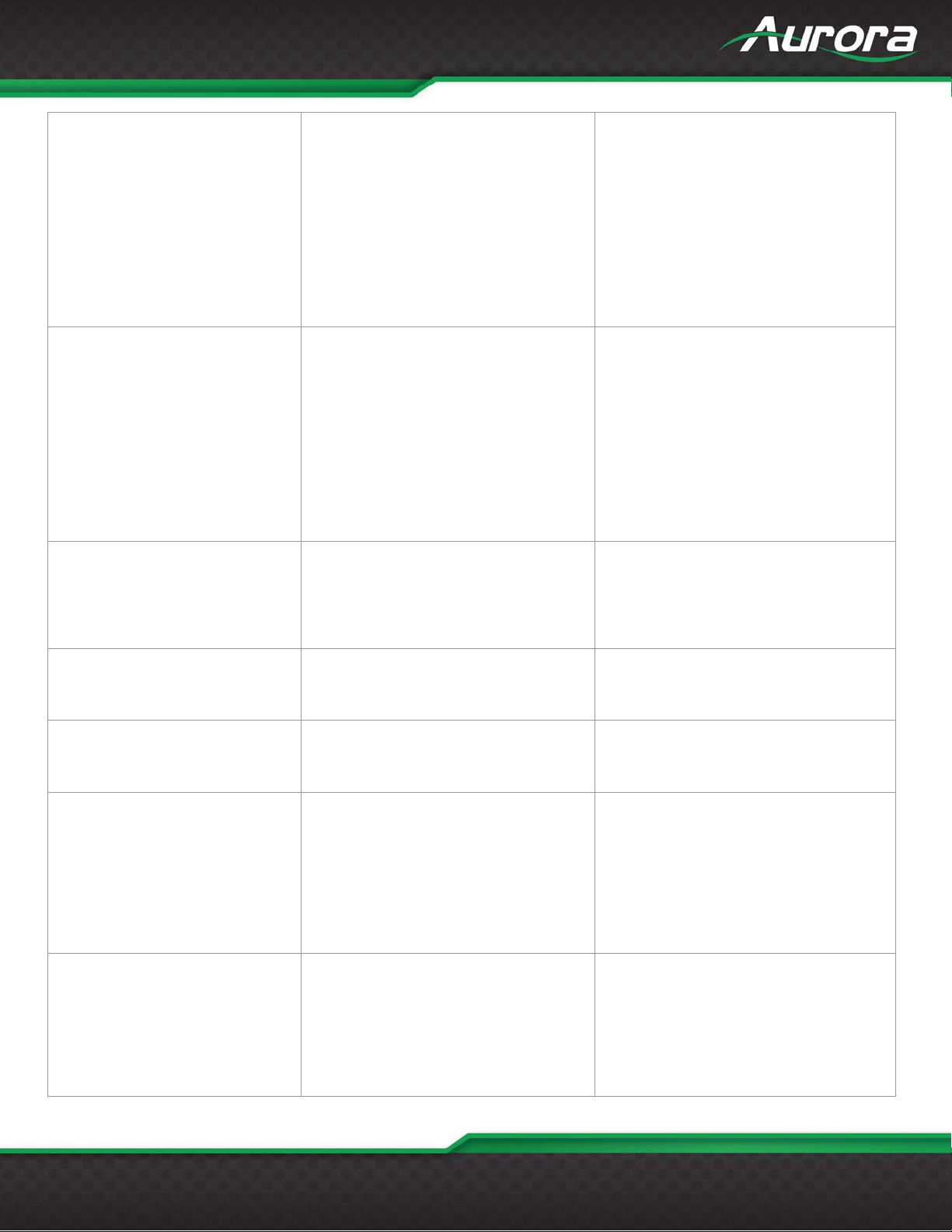
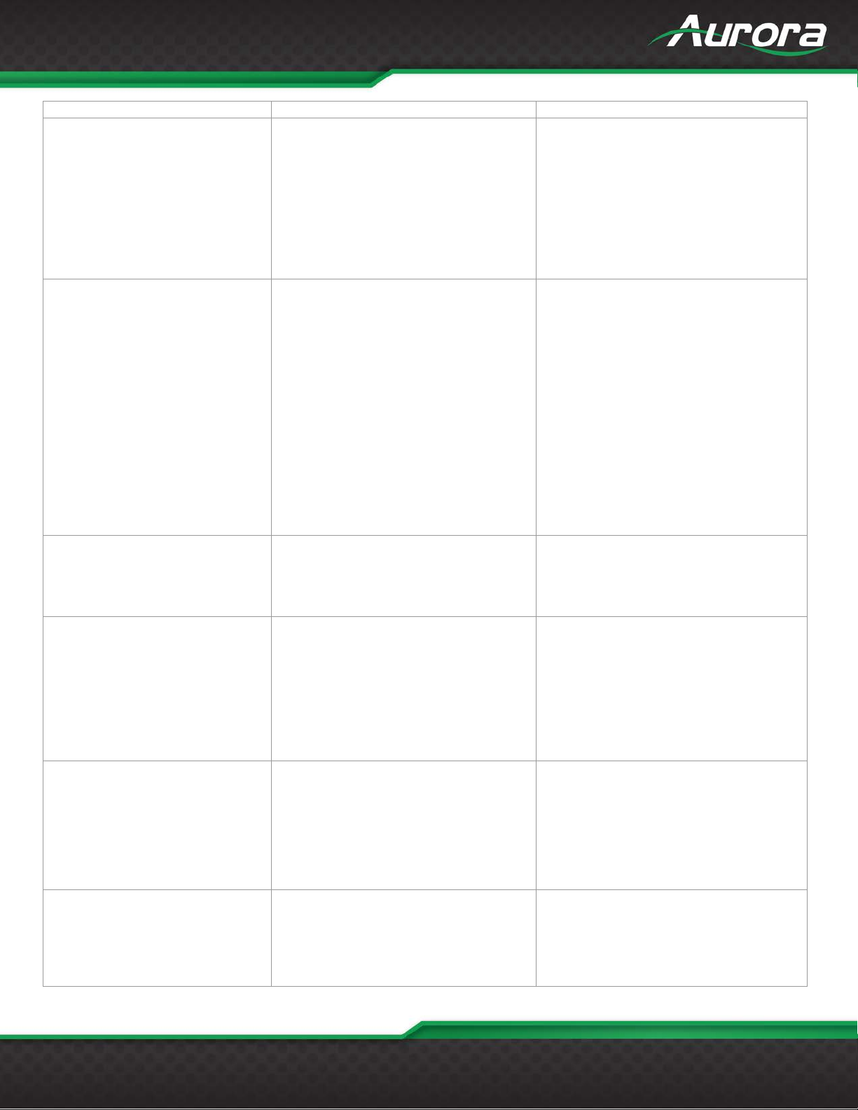
A user can issue RPC commands to control the device. The RPC command will have the following
format:
method=<function_name>¶m1=<parameter1>¶m2=< parameter1>…
• The method field is the RPC function name.
• The paramX field is the parameter field. Parameter depends on the function used. The number
of parameters will also vary. X = 0 or 1 or 2… depending on the function.
The following are the RPC commands.
Reboot method=Reboot
UpdateBootloader method=UpdateBootloader
method=Net_SetStaticIP¶m1
Net_SetStaticIP
Serial_SetSettings
ButtonLock
Net_SetDHCP method=Net_SetDHCP
=<ip>¶m2=<netmask>¶m3=<
gateway>
method=Serial_SetSettings&Param1=<
Baud_Rate>,<data_bits>,<parity>,<stop
_bits>
method=ButtonLock&Param1=<enable/
disable>
eg:
bootloader
eg:
eg:
method=Net_SetStaticIP&Param1=
192.168.1.10&Param2=255.255.25
Valid baud rates: 15200, 57600, 38400,
19200, 14400, 9600, 4800, 2400, 1200.
Valid data bits: 8, 7.
Valid parity: O, E, N. (O – Odd, E –
Even, N – None).
eg:
method=Serial_SetSettings
eg:
method=ButtonLock&Param1=enabl
eg:
Net_SetAutoIP method=Net_SetAutoIP
IR_CarrierStrip
method=IR_CarrierStrip&Param1=<ena
ble/disable>
eg:
Removes the carrier from the IR signal
from the HDBT and outputs to external
IR Transmitter.
Note: A device can have IR carrier
removal enabled either at transmitter or
Page 30

USERS GUIDE
www.auroramm.com
29
enabling at TX disables at RX and vice
enable
Inverts the IR signal from the HDBT and
e
Removes the carrier from the IR signal
am1=<enable/disable>
Inverts the IR signal from the IR Remote
¶m1=enable
<input> :linein, dante,hdmi
nein &Param2=lineout
Switches to the particular video source.
n1
Defaults the file system. After defaulting,
method=DefaultFileSystem
Factory defaults the HTE/HTW to default
Static netmask = 255.255.255.0
versa
eg:
method=IR_CarrierStrip&Param1=
IR_Inverse
IR_HDBTCarrierStrip
IR_HDBTCarrierInverse
SetAudioRoute
method=IR_Inverse&Param1=<enable/
disable>
method=IR_HDBTCarrierStrip&Param1
=<enable/disable>
method=IR_HDBTCarrierInverse
¶m1=<enable/disable>
method=SetAudioRoute&Param1=<inp
ut>¶m2=<output>
outputs to external IR Transmitter.
eg:
method=IR_Inverse&Param1=enabl
from the HDBT and outputs to external
IR Transmitter.
Note: A device can have IR carrier
removal enabled either at transmitter or
at the receiver side. But not both. So,
enabling at TX disables at RX and vice
versa.eg:
method=IR_HDBTCarrierStrip&Par
and outputs to HDBT.
Note: It is enabled by default.
eg:
method=IR_HDBTCarrierInverse
remote_audio, arc
<output> lineout, dante,stream_audio,
remote_audio
Note:
stream_audio is only for TX and arc is
only for RX
eg:
method=SetAudioRoute&Param1=li
SetVideoSource
DefaultFileSystem method=DefaultFileSystem
SetDefaultConfig method=SetDefaultConfig
method=SetVideoSource¶m1=<src
>
This command is applicable only for tx.
<src>: in1, in2 & in3(for wallplate)
command is meant only for TX
eg:
method=SetVideoSource&Param1=i
the device will reboot with /IR and
/wwwpub directories present.eg:
configuration.
The default configuration is:
IP mode = Auto-IP
Static ip = 192.168.1.10
Page 31
USERS GUIDE
www.auroramm.com
30
Static gw = 192.168.1.1
method=SetDefaultConfig
Sets the USB mode
e
Sets the analog audio volume
inein&Param2=99
Simulates a button press.
method=ButtonPress&Param1=2
Simulates a button Release.
method=ButtonRelease&Param1=2
Sets the button color. Only applicable for
&Param2=Press&Param3=Magenta
param1=1,2,3(wallplate)
method=SetButtonMode&Param1=2&
SetUsbMode SetUsbMode&Param1=<host/device>
Serial conf = 115200-8n1
Password = admin
Button Lock = Disabled
IR Carrier removal = Disabled
IR Carrier reversal = Disabled
Port Processing mode = Extender mode
USB mode (TX/HTW) = Host
USB mode (RX) = Device
eg:
Note:
If a video stream is in progress, then
it will be stopped for a moment.
Note:
Whenever the USB mode is changed,
there will be a ‘0x00’ character in the
UART.
param1 = host, device
eg:
method=SetUsbMode&Param1=Devic
SetAudioVolume
ButtonPress ButtonPress&Param1=<button_no>
ButtonRelease
SetButtonColor
SetButtonMode
SetAudioVolume&Param1=<analog_au
dio_port> &Param2=<au dio _v al>
method=ButtonRelease&Param1=<butt
on_num>
method=SetButtonColor&Param1=<butt
on_num>&Param2=<press/release>&P
aram3=MAGENTA
SetButtonMode&Param1=<button_num
>&Param2=<press/relese>¶m3=<
mode>
param1 = linein, lineout.
param2 = 0 -100, mute,un mute
eg:
method=SetAudioVolume&Param1=l
param1 = 1, 2, 3(wallplate)
eg:
param1 = 1, 2, 3(wallplate)
eg:
wallplate.
colours: red, blue, green, yellow, cyan,
white, magenta, none
param1 = 1,2, 3(wallplate)
param2 = press, release
eg:
method=SetButtonColor&Param1=2
param2=press/release
param3=tcp,serial,default
default mode is applicable only for
release mode. Default mode is video
source selection.
eg:
Page 32
USERS GUIDE
www.auroramm.com
31
Param2=PRESS&Param3=Serial
Clears the button mode.
2&Param2=Press&Param3=Serial
param1=1,2,3(wallplate)
ram4=abcd&Param5=1
Serial data will be stored in an internal
method=Serial_SetManualMode
Serial data is pushed to the other
Serial data will be push ed to port of the
&Param1=192.168.1.100&Param2=1
Serial data will be stored in the set
method=
ClearButtonMode
SetButtonParam
ClearButtonMode&Param1=<button_nu
m>
&Param2=<press_mode>&Param3=<m
ode>
SetButtonParam&Param1=<button_nu
mber>&Param2=<press_mode>&Paar
m3=<command_mode>&Param4=<com
mand_string>&Param5=<port/ip_addr>
&Param6= <telnet_port>
param1=1,2,3(wallplate)
param2=press/release
param3=tcp,serial,default
default mode is applicable only for
release mode. Default mode is video
source selection.
eg:
method=ClearButtonMode&Param1=
param2=press/release
param3=tcp,serial,default
param4=string in quotes
param5= serial port num eg 1 in case
serial mode and ip address in case of tcp
mode
param6=tcp port in case of tcp mode
eg:
method=SetButtonParam&Param1=1
&Param2=press&Param3=tcp&Param
4=abcd&Param5=192.168.1.10&Par
am6= 6000
method=SetButtonParam&Param1=1
&Param2=press&Param3=serial&Pa
Serial_SetManualMode Serial_SetManualMode
Serial_SetExtenderMode Serial_SetExtenderMode
Serial_SetPushPortMode
Serial_SetPushVarMode
Serial_SetPushPortMode
Serial_SetPushVarMode,
buffer to be retrieved later by appropriate
commands
eg:
connected device.
param1=0( extender mode),1( mirror
mode)
eg:
method=
Serial_SetExtenderMode¶m1=
0
device with the set ip address
param1=ip address
param2 = serial_port number
eg:
method= Serial_
SetPushPortMode
variable of a device with the set ip
param1= ip address
param2= var name
eg:
Page 33

USERS GUIDE
www.auroramm.com
32
Serial_SetPushVarMode&Param1=1
92.168.1.100&Param2=abcd
Serial data will be pushed to the device
=5000
Serial data will be pushed to the
Send the ir command stored in the
ir &Param2=ON
List all the ir files in the devi c e
method=IR_ListIRGroups
Lists all the commands in the queried
1=1000.wir
Lists all audio routing informations
in
Get the analog audio volume
inein
Returns the selected video source.
method=GetVideoSource
param1=1,2, 3 (wallplate)
Param2=press&Param3=tcp
Net_GetIPAddress
method= Net_GetIPAddress,
3 commands to get ip, subnet, gateway
Serial_SetTelnetClientMode
Serial_SetTelnetServerMode Serial_SetTelnetServerMode
Serial_SetTelnetClientMode,
with ip and port number runninc a tcp
server.
param1=tcp server ip address
param2=tcp server port number
eg:
method=Serial_SetTelnetClientM
ode¶m1=192.168.1.10¶m2
connected tcp client.
param1=tcp server port number
eg:
method=Serial_SetTelnetServerM
ode¶m1=5000
IR_SendIR
IR_ListIRGroups IR_ListIRGroups
IR_ListIRCommands
GetAudioRoute GetAudioRoute
GetAudioVolume
IR_SendIR&Param1=<filename>
&Param2=<command_name>
method=IR_ListIRCommands&Param1
=<filename>
GetAudioVolume¶m1=
<linein/lineout>
filename in the internal filesystem.
eg:
method=IR_SendIR&Param1=sony.w
eg:
filename.
eg:
method=IR_ListIRCommands&Param
eg:
method=GetAudioRoute
Response:
status=1&response1=lineout:non
e,dante:none,remote_audio:vide
o_src_audio,stream_audio:line_
Param1= linein, lineout
eg:
method=GetAudioVolume&Param1=l
GetVideoSource GetVideoSource
GetButtonMode
GetButtonMode&Param1=
<button_num>&Param2=<press_mode
>&Param3=<press_mode>
Applicable only in TX
eg:
param2=press, release
param3=tcp, serial
eg:
method=GetButtonMode&Param1=1&
Page 34

USERS GUIDE
www.auroramm.com
33
Net_GetSubnetMask,
method=Net_GetSubnetMask
eg:
method= Net_GetGateway
Returns the last set static ip of the device
method= Net_GetStaticIP
Returns the ip mode: autoip, dhcp, static
method=Net_GetNetworkMode
Returns the stored button param
=1¶m2=press¶m3=serial
Returns the set button colors in
¶m1=1¶m2=press
Returns the mac id
method= Net_GetMac
Returns the serial settings
1
Returns the current USB Mode
method=GetUSBMode
Returns the serial number of the device
method= GetSerialNumber
Returns the button lock value.
method= GetButtonLock
Returns the firmware version number
method= GetFirmwareVersion
Returns the expolore version number
method= GetExploreVersion
Returns the command api version
method=GetApiVersion
Returns the Silicon device firmware
method= GetSilFWVersion
GetBootloaderPresence
GetBootloaderPresence
Returns whether bootloader is present or
Net_GetGateway
Net_GetStaticIP Net_GetStaticIP
Net_GetNetworkMode Net_GetNetworkMode
get_button_param <button_num>
<press_mode>
<command_mode>
GetButtonColor <button_num>
<press_mode>
Net_GetMac Net_GetMac
Serial_GetSettings Serial_GetSettings
method= Net_GetGateway
get_button_param
¶m1=<button_num>
¶m2=<press_mode>
¶m3=<command_mode>
GetButtonColor&Param1=<button_num
>&Param2=<press_mode>
method= Net_GetIPAddress
method=Net_GetSubnetMask
eg:
eg:
param1=1,2, 3 (wallplate)
param2=press, release
param3=tcp, serial
eg:
method=get_button_param¶m1
wallplate.
eg:
method= GetButtonColor
eg:
Eg: method= Serial_GetSettings
Response:
status=1&response1=115200,8,N,
GetUSBMode GetUSBMode
GetSerialNumber GetSerialNumber
GetButtonLock GetButtonLock
GetFirmwareVersion GetFirmwareVersion
GetExploreVersion GetExploreVersion
GetApiVersion GetApiVersion
GetSilFWVersion GetSilFWVersion
eg:
eg:
eg:
eg:
eg:
number
eg:
version
eg:
Page 35

USERS GUIDE
www.auroramm.com
34
not.
method= GetBootloaderPresence
Returns the IR inverse value
method= IR_GetInverse
Returns the IR carrier strip value
method= IR_GetCarrierStrip
Returns the IR HDBT carrier inverse
e
Returns the HDBT carrier strip value
method= IR_GetHDBTCarrierStrip
Sends the serial string via the serial
bcdӦm3=0
This returns the contents inside the serial
method= Serial_Read
Clears the serial buffer. Applicable only
method= Serial_ClearReadBuffer
Returns the serial internal buffer count.
method= Serial_ReadBufferCount
Returns the total number of serial ports
method=Serial_GetPortCount
Returns the autosense status
method=GetAutoSense
Sets the auto sense
SetAutoSense&Param1=enable
Sets the video source
eg:
eg:
IR_GetInverse IR_GetInverse
IR_GetCarrierStrip IR_GetCarrierStrip
IR_GetHDBTCarrierInverse IR_GetHDBTCarrierInverse
IR_GetHDBTCarrierStrip IR_GetHDBTCarrierStrip
Serial_Send
Serial_Read Serial_Read
Serial_ClearReadBuffer Serial_ClearReadBuffer
Serial_Send&Param1=<port>¶m2=
<serial_string>¶m3=0
eg:
eg:
value.
eg:
method=IR_GetHDBTCarrierInvers
eg:
output port
eg:
method=
Serial_Send&Param1=1¶m2=”a
buffer. Applicable only when manual
method is selected
eg:
in manual method
Serial_ReadBufferCount Serial_ReadBufferCount
Serial_GetPortCount Serial_GetPortCount
GetAutoSense GetAutoSense
SetAutoSense
SetVideoSourcePriority
SetAutoSense&Param1=
<enable/disable>
SetVideoSourcePriority&Param1=<vidS
ource_num>¶m2=<priority_val>
Applicable only in manual method
in the device
Applicable only in HTE TX Devices
Applicable only in HTE TX Devices
method=
Param1=1,2,3(vid source
number)
Param2=1,2,3 (priority val)
Priority val is maximum 3 in
wallplate and maximum 2 in box
version
This command is applicable
only in tx
Page 36

USERS GUIDE
www.auroramm.com
35
method=
in1¶m2=3
Returns the priority of the source number
Param1=1
GetVideoSourcePriority
GetVideoSourcePriority&Param1=<sour
ce num>
SetVideoSourcePriority&Param1=
Applicable only in HTE TX Devices
param1=source num
eg:
method=GetVideoSourcePriority&
Page 37
USERS GUIDE
www.auroramm.com
36
Modify or set the audio routing in HTE.
set_audio_route linein stream_audio
Controls the linein and lineout volum e.
set_volume lineout 85
Configure the IP address of the device
set_ip DHCP
Filename: Name of the file containing pronto codes.
Eg: Send_ir sony.wir PLAY
Lists the IR files stored in the device;
Eg: list_ir_groups
Lists the IR commands listed in an IR File.
list_ircmds sony.wir
Displays the full info of the Audio routing in the device
Eg: get_audio_route
Returns the Volume of the Line in audio or Lineout
Eg: get_volume linein
Baud Rate: 1200, 2400, 4800, 9600, 19200, 38400,
signal_level: RS232
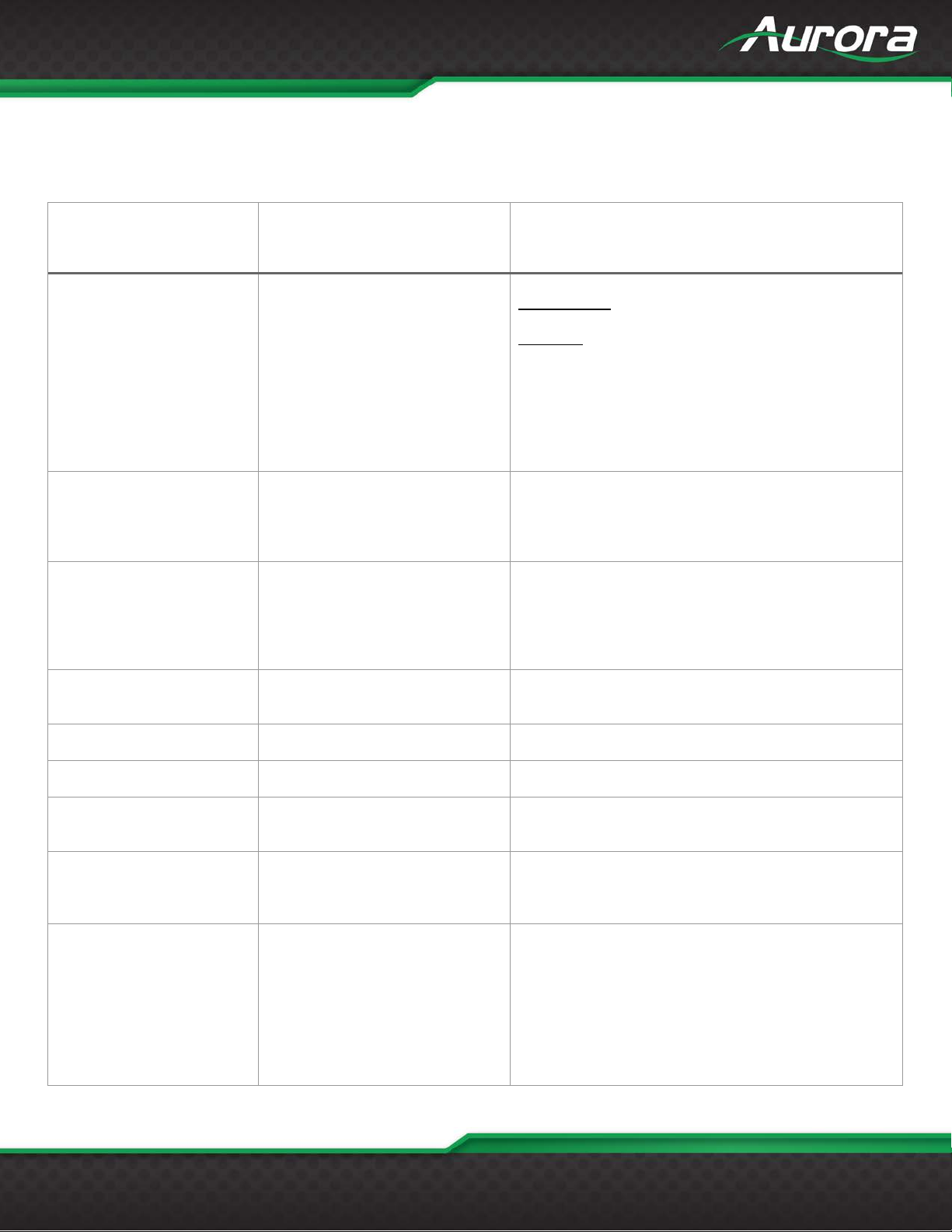
ReAX TCP Commands
The device parameters can be controlled by ReAX commands. A TCP server is running at the port 6970 which listens for
the ReAX command and responds in JSON format accordingly.
ReAX Command String Format Information
Route From:
none, linein, dante, hdmi, remote_audio, arc
Route To
Lineout, dante, stream_audio, remote_audio
We can insert audio to stream_audio only from TX
and not from RX.
Eg:
set_audio_route linein lineout
set_audio_route
set_audio_route <route_from>
<route_to>
set_volume
set_ip
send_ir
Set_volume <audio_port>
<volume_level>
set_ip <ip_mode> <ip_addr>
<subnet> <gateway>
send_ir <filename>
<command_name>
list_ir_groups list_ir_groups
list_ircmds list_ircmds <file_name>
get_audio_route get_audio_route
get_volume get_volume <audio_port>
Audio_port: linein, lineout
Volume_level: 0-100, mute, unmute
set_volume linein mute
Ip_mode: DHCP, static, auto_ip
Eg: set_ip static 192.168.1.101 255.255.0.0
192.168.1.1
set_ip auto_ip
Command_name: Name of the IR command
of the current selected source
audio.
Audio_port: linein, lineout
config_rs232 <port_no.>
<baud_rate> <data_bit>
config_rs232
<stop_bit> <parity>
<hand_shaking>
<signal_level>
57600, 115200
Port Number: 1
baud_rate: 1200, 2400, 4800, 9600, 19200, 38400,
57600, 115200
Data_bit: 7, 8
Parity: n,o,e
Handshaking: none, software
Page 38

USERS GUIDE
www.auroramm.com
37
Example: config_rs232 1 115200 8 1 n none RS232
Video_port: hdmi1, hdmi2, v ga
Set_video_source vga
Returns the current video source that is being
get_video_source
Configures the button mode to send serial, TCP
set_button_mode 1 release serial
Returns all the modes that are set against a button
get_button_mode 2 release
Clears the button from the mode that is selected with
Clear_button_mode 1 default
Only for wallplate:
set_button_color 1 release blu e
Set the button parameters that is used when a button
established before sending.
set_video_source
set_video_source
<video_port>
get_video_source get_video_source
set_button_mode
set_button_mode
<button_number>
<press_mode>
<button_mode>
get_button_mode
Get_button_mode
<button_num> <press_mode>
Eg:
Set_video_source hdmi1
streamed.
Eg:
commands and default functionality all in a single
press/release or any combination
button_number: 1,2,3 (only for wallplate)
press_mode: press, release
button_mode: TCP, serial, default
Note: The command that has to be send on
pressing/releasing a button has to be configured via a
separate ReAX command
Eg:
set_button_mode 1 release TCP
press/release.
Button_num: 1,2,3
Press_mode: press, release
Eg:
clear_button_mode
clear_button_mode
<button_num> <press_mode>
set_button_color
set_button_color
<button_num> <press_mode>
<button_color>
set_button_param
<button_number>
set_button_param
<press_mode>
<command_mode>
<command_string>
<port/ip_addr> <telnet_port>
command
Button_num: 1,2,3
Press_mode: press, release
Eg:
Clear_button_mode 1 serial
Configures the button color:
Colors can be selected from red, blue, green, white,
yellow, cyan, magenta, none
set_button_color 1 press green
is pressed or released corresponding to the mode set
against that button.
Button_num: 1,2,3
press_mode; press, release
command_mode: serial, TCP
command_string: string with length of max 256 length
with support for escape characters enclosed in double
quotes
port: serial_port number in case of serial mode
ip_addr: ip address in case in case of TCP
telnet_port: Tcp port to which connection should be
Page 39

USERS GUIDE
www.auroramm.com
38
Eg:
Set_button_param 1 release TCP 192.168.1.10 5000
Returns the Current IP of the device
get_ip
Returns the last saved static IP address
get_ip_static
Configures the port processing method for the device.
Query the string stored against a mode(tcp/serial) in
Get_button_param 1 release TCP
Button_num: 1,2,3
get_button_color 1 press
get_mac
get_mac
Returns the mac id of the device
get_mac
get_rs232
get_rs232 <port_num>
Returns the rs232 configuration values
get_rs232 1
serial_read
serial_read <port_num>
Returns the serial buffer when in manual method
serial_read 1
serial_clear_buffer
serial_clear_buffer
Clears the serial buffer when port processing is
serial_clear_buffer 1
get_serial_buffer_count
get_serial_buffer_count
Returns the buffer count when the port processing
Eg:
Set_button_param 1 press serial 1 “abc123”
get_ip get_ip
get_ip_static get_ip_static
set_remote_session <mode>
set_remote_session
<ip_addr>
<mode_specific_param>
get_button_param
get_button_param
<button_num> <press_mode>
<command_mode>
Eg:
Eg;
Mode: telnet_client, telnet_server, extender , ma nua l,
push_to_port, push_to_var
Ip: ip address
Port : tcp port
Serial_port: serial port number.
Eg: set_remote_session telnet_client <ip> <port>
Set_remote_session telnet_server <port>
Set_remote_session extender
Set_remote_session manual
Set_remote_session push_to_port <ip> <serial_port>
Set_remote_session push_to_var <ip> <var>
button press/release
Button_num: 1,2,3
Press_mode: press, release
Command_mode: TCP, serial
Eg:
get_button_color
get_button_color
<button_num> <press_mode>
<port_num>
<port_num>
Press_mode: press, release
Eg;
Eg:
port_num: 1 or 2
Eg:
port_num: 1
Eg:
selected as manual method
port_num: 1
eg:
mode is selected as manual method
port num = 1
Page 40

USERS GUIDE
www.auroramm.com
39
get_serial_buffer_count 1
get_serial_port_count
get_serial_port_count
Returns the total serial port count
get_serial_port_count
get_auto_sense
get_auto_sense
Returns the auto sense status
get_auto_sense
set_auto_sense
set_auto_sense
Control auto sense feature
set_auto_sense enable
reboot
reboot
Reboots THE
reboot
update_bootloader
update_bootloader
Enters the tftp mode to receive the bootloader
update_bootloader
update_firmware
update_firmware
Enters the bootloader mode to receive the new
update_firmware
button_lock
button_lock <enable/disable>
Controls the button lock
button_lock disable
set_ip DHCP
set_ip DHCP
Sets the device in to DHCP Mode
set_ip DHCP
set_ip auto_ip
set_ip auto_ip
Eg:
set_ip auto_ip
ir_carrier_strip
ir_carrier_strip
Removes the carrier from the IR signal from the HDBT
ir_carrier_strip enable
ir_inverse
ir_inverse <enable/disable>
Inverts the IR signal from the HDBT and outputs to
ir_inverse enable
hdbt_ir_carrier_strip
hdbt_ir_carrier_strip
Removes the carrier in the IR signal from the IR
hdbt_ir_carrier_strip enable
hdbt_ir_carrier_inverse
hdbt_ir_carrier_inverse
Inverts the IR signal from the IR Remote and outputs
hdbt_ir_carrier_inverse enable
filesystem_default
filesystem_default
Defaults the file system. After defaulting, the device
Eg:
Eg:
<enable/disable>
<enable/disable>
Eg:
Eg:
firmware via tftp
Eg:
firmware via tftp. After timeout if no firmware is
received the previous firmare is loaded.
Eg:
Eg:
Eg:
and outputs to external IR Transmitter.
Note: A device can have IR carrier removal enabled
either at transmitter or at the receiver side. But not
both. So, enabling at TX disables at RX and vice
versa.Eg:
<enable/disable>
<enable/disable>
external IR Transmitter.
Eg:
Remote and outputs to HDBT.
Note: A device can have IR carrier removal enabled
either at transmitter or at the receiver side. But not
both. So, enabling at TX disables at RX and vice
versa.Eg:
to HDBT.
Note: It is enabled by default.
Eg:
Page 41

USERS GUIDE
www.auroramm.com
40
will reboot with /IR and /wwwpub directories present.
filesystem_default
factory_default
factory_default
Factory defaults the HTE/HTW to default
factory_default
set_usb_mode
set_usb_mode <host/device>
Sets the USB mode
set_usb_mode host
button_press
button_press
Simulates the button press
button_press 1
button_release
button_release
Simulates button release
button_release 1
get_usb_mode
get_usb_mode
Returns the current usb mode
get_usb_mode
get_serial_number
get_serial_number
Returns the serial number of device
get_serial_number
get_button_lock
get_button_lock
Returns the button lock status
get_button_lock
get_fw_version
get_fw_version
Returns the firmware version
get_fw_version
get_explore_version
get_explore_version
Returns the explore firmware version
get_explore_version
get_api_version
get_api_version
Returns the command api version
Eg:
Eg:
configuration.
The default configuration is:
IP mode = Auto-IP
Static ip = 192.168.1.10
Static netmask = 255.255.255.0
Static gw = 192.168.1.1
Serial conf = 115200-8n1
Password = admin
Button Lock = Disabled
IR Carrier removal = Disabled
IR Carrier reversal = Disabled
Port Processing mode = Extender mode
USB mode (TX/HTW) = Host
USB mode (RX) = DeviceEg:
Note:
If a video stream is in progress, then it will be
stopped for a moment.
Note:
Whenever the USB mode is changed, there will be
a ‘0x00’ character in the UART.
Eg:
<button_number>
<button_number>
button_number: 1,2, 3(wallplate)
eg:
button_number: 1,2,3(wallplate)
eg:
Eg:
Eg:
Eg:
Eg:
Eg:
Page 42
USERS GUIDE
www.auroramm.com
41
get_api_version
get_sil8784_fw_version
get_sil8784_fw_version
Returns the silicon device firmware
get_sil8784_fw_version
get_bootloader_presence
get_bootloader_presence
show whether bootloader is present
get_bootloader_presence
get_ir_inverse
get_ir_inverse
Returns the status of ir inverse
get_ir_inverse
get_ir_carrier_strip
get_ir_carrier_strip
Returns the status of IR carrier strip
get_ir_carrier_strip
get_hdbt_ir_inverse
get_hdbt_ir_inverse
Returns the status of hdbt ir inverse status
get_hdbt_ir_inverse
get_hdbt_ir_carrier_strip
get_hdbt_ir_carrier_strip
Returns the hdbt ir carrier strip status
get_hdbt_ir_carrier_strip
serial_send
serial_send <port> <string>
Send the serial string via the serial port in the
serial_send 1 “abcd”
Eg:
Eg:
Eg:
Eg:
Eg:
Eg:
command
The string should be enclosed in quotes
Audio Routing Set Commands
Command Input Output
set_audio_route none lineout
linein dante
dante st r eam_audio(applicable only in tx)
hdmi remote_audio
remote_audio
arc
Line in to various outputs
set_audio_route linein lineout
set_audio_route linein dante
set_audio_route linein stream_audio (only in Tx)
set_audio_route linein remote_audio
Dante to various outputs
set_audio_route dante lineout
set_audio_route dante dante
set_audio_route dante stream_audio(only in Tx)
set_audio_route dante remote_audio
Page 43

USERS GUIDE
www.auroramm.com
42
Input video audio to various outputs - Applicable only at TX
set_audio_route hdmi lineout
set_audio_route hdmi dante
set_audio_route hdmi stream_audio(default option)
set_audio_route hdmi remote_audio
Remote Audio (audio that comes from Rx in case of Tx and Tx in case of Rx) to Various outputs
set_audio_route remote_audio lineout
set_audio_route remote_audio dante
set_audio_route remote_audio stream_audio(only in Tx)
set_audio_route remote_audio remote_audio
Arc to Various outputs - Applicable only at RX
set_audio_route arc lineout
set_audio_route arc dante
set_audio_route arc remote_audio
Note: for TCP commands
"arc" as input is applicable only for HTE RX
"hdmi" as input is only applicable for TX as input video audio is only available at Tx. In wall plate it is available
only for HDMI inputs and not VGA inputs
stream_audio as output is only applicable for TX as we do not support audio insertion to video at RX side.
Eg: set_audio_route <xxxx> stream_audio (not valid for rx)
set_audio_route hdmi <xxx> (not valid for rx) as input video source is only present at tx side
set_audio_route arc <xxx> (not valid for TX)
Page 44
USERS GUIDE
www.auroramm.com
43
Audio Routing Query Command
get_audio_route
Note
To Support Audio Insertion to the video at RX side we have to do it by first inserting the audio at rx side to
remote audio. It will reach the Tx and at the tx we should insert the remote audio to stream_audio.
For Eg: To insert the line in at RX to the stream video at RX enter the following commands
1) Insert line in to remote audio at Rx - !**AUD1,4 or set_audio_route linein remote
2) Insert remote audio to stream audio at Tx - !**AUD4,3 or set_audio_route remote_audio stream_audio
Brief Description of Button mode and Button Color
Each button has 3 independent modes and these modes can be set for press and release separately. The
default functionality for buttons in TX for release is input switching. Each mode can be independently set as
well as cleared.
Button_numbers are 1,2 for box version and 1,2 & 3(for wall plate)
Press_modes are press and release
Button_modes are tcp, serial and default
button_color: none, white, red, green, blue, yellow, magenta, cyan
TCP mode means a TCP msg can be send when we press/release a button
serial mode means a serial message can be send when we press/release a button
Telnet commands
Set Button Modes
set_button_mode <button_number> <press_mode> <button_Mode>
Eg:
set_button_mode <button_number> <press_mode> <button_Mode>
set_button_mode 1 press tcp
set_button_mode 1 release tcp
Clear Button Modes
clear_button_mode <button_mode> <press_mode> <button_mode>
Eg:
clear_button_mode 1 release tcp
Page 45

USERS GUIDE
www.auroramm.com
44
Query button mode
get_button_mode <button_number> <press_mode>
Set Button Color
set_button_color <button_number> <press_mode> <button_color>
Eg:
set_button_color 1 release white
set_button_color 1 press blue
Query Button Color
get_button_color <button_number> <press_mode>
get_button_color 1 release
Set Button Parameters
set_button_param <button_number> <press_mode> <command_mode> <command_string>
<serial_port/ip_addr> <tcp_port(optional only in case of tcp)>
set_button_param 2 release serial "abc\r" 1
set_button_param 1 press tcp "abc123\r" 192.168.1.10 6780
Query Button Parameters
get_button_param <button_number> <press_mode> <command_mode>
get_button_param 2 press serial
Page 46
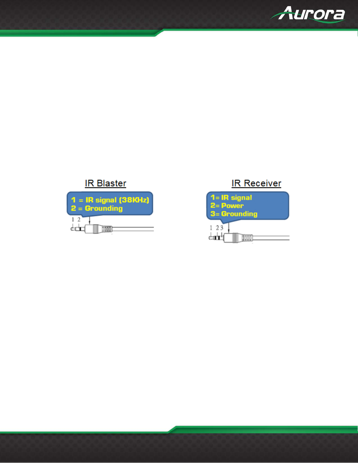
USERS GUIDE
www.auroramm.com
45
IR EXTENDERS
IR Connections
IR Blaster/Emitter. Plug in an IR bl aster to emit all I R command signals r eceived from the IR receiver to contr ol the
associated devices with built-in IR sensor.
IR Receiver. Plug in an IR rec eiver to receive all IR c ommand signals from the IR remote con trols of the assoc iated
devices.
*Note: If you are not using an approved Aurora branded receiver, make cer tain you do not exceed t he 5v signal
level limitation as some devices u se 12v. Also, I R Receiver must be 30K-60KHz inverted 5V signal. Failure to do
so will result in damage.
IR Jack Pinout
*Note: Emitters must be mono or have ring and sleev e tied to ground. Receivers must be stereo plug. Ring is 5v
power. If using another brand receiver, note carrier frequency must be present, IR signal inverted, and IR signal
cannot exceed 5v or damage to port may occur.
Page 47
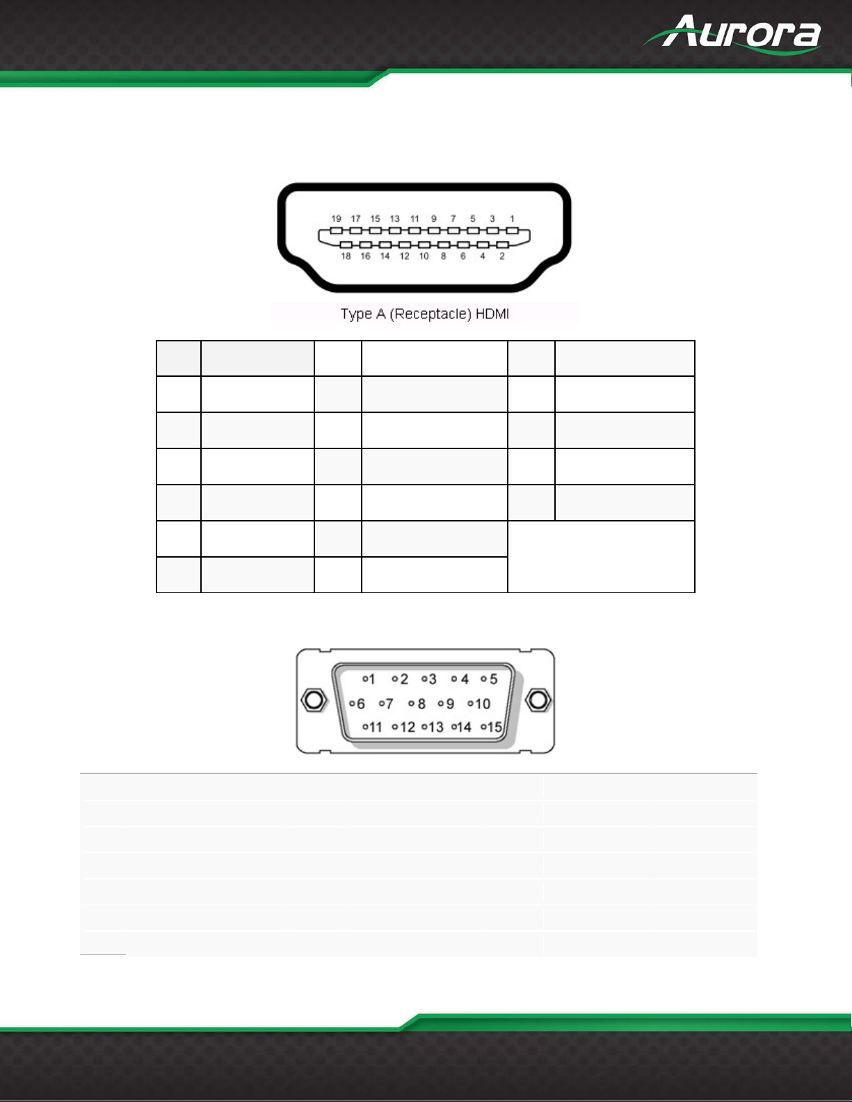
USERS GUIDE
www.auroramm.com
46
Pin
1
Red (Pr)
Pin
8
Ground
Pin
15
SCL
Pin
2
Green (Y, S-Video C)
Pin
9
5v
Pin
3
Blue (Pb)
Pin
10
SYNC Ground
Pin
4
Composite (S-Video Y)
Pin
11
NC
Pin
5
Ground
Pin
12
SDA
Pin
6
Ground
Pin
13
Horizontal Sync
Pin
7
Ground
Pin
14
Horizontal Sync
CONNECTOR PIN DEFINITION
HDMI
VGA
TMDS Data2+
Pin 1
Pin 2 TMDS Data2 Shield Pin 9 TMDS Data0–
Pin 3 TMDS Data2–
Pin 4 TMDS Data1+
Pin 5 TMDS Data1 Shield Pin 12 TMDS Clock–
Pin 6 TMDS Data1–
Pin 7 TMDS Data0+
Pin 8 TMDS Data0 Shield
Pin 10 TMDS Clock+
Pin 11 TMDS Clock Shield
Pin 13 CEC
Pin 14 Reserved (N.C. on device)
Pin 15 SCL
Pin 16 SDA
Pin 17 DDC/CEC Ground
Pin 18 +5 V Power
Pin 19 Hot Plug Detect
Page 48
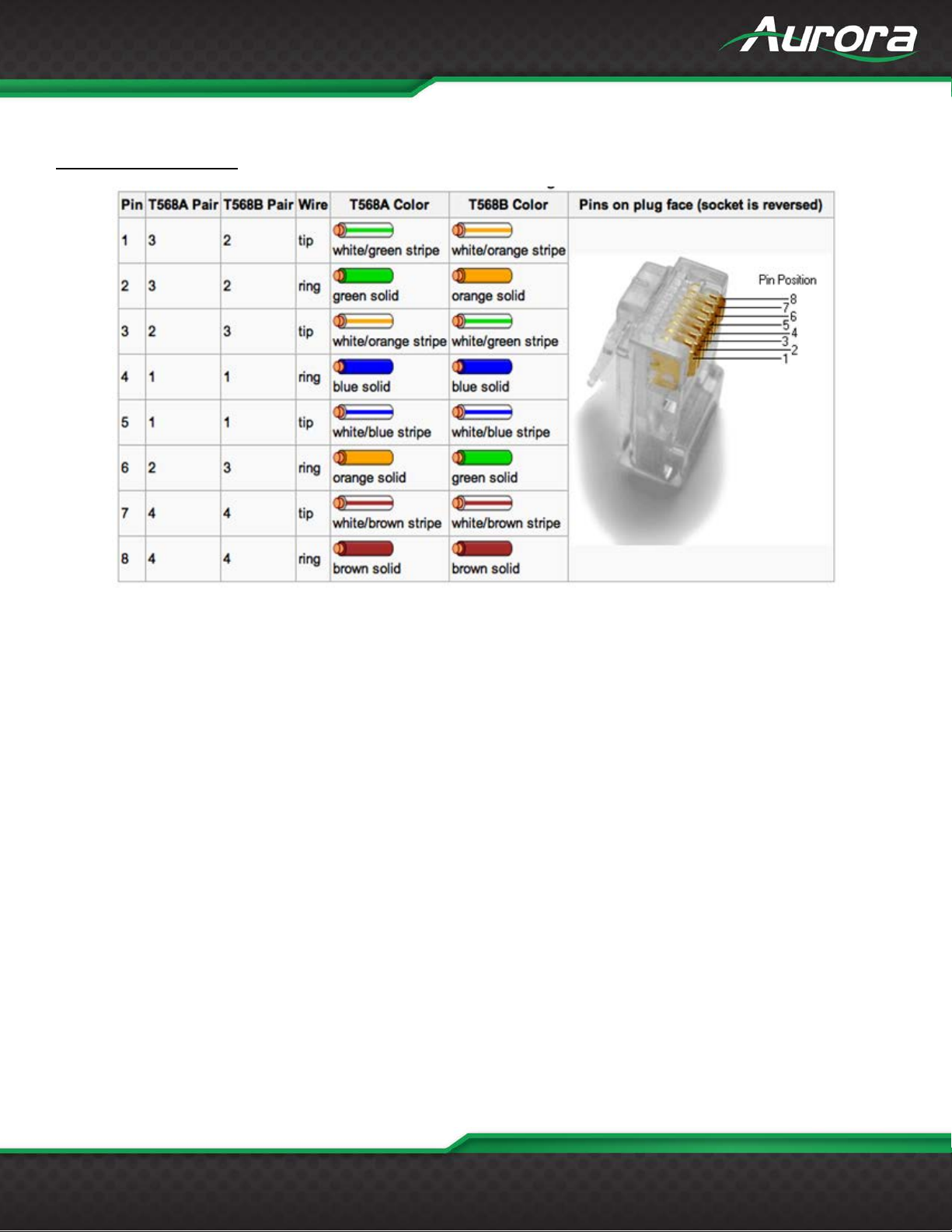
USERS GUIDE
www.auroramm.com
47
CAT5e/6/7
T568A and T568B Wiring
Page 49
USERS GUIDE
www.auroramm.com
48
Problem
Solution
a. Check that the power plug is properly inserted into a functioning power outlet. Keep in
c. Verify pin-out of connector at each end.
a. Check 48v power supply is plugged in locally or at the far end receiver unit.
d. Make certain RS-232 command for LED state is not set to none for both buttons.
a. Verify using proper emitter at receiver unit. Use Aurora branded accessories for best
results.
a. Tot al power be tween the 2 ports is 5 wat ts. If excee ded the current protection will kick in
before plugging in 2 devices.
a. Make certain proper power supply wattage is being used to power both HTW-2 a nd the
receiver. Refer to technical specifications for more info on power consumption.
a. Check if remote receiver is supplying power.
receiver. Refer to technical specifications for more info on power consumption.
8. Cer tain functions lis ted in manual
do not function
a. The HT Series does not scale. Check the display’s settings for over-scan mode. Displays
secondary when dealing with video resolutions.
APPENDIX 1
Troubleshooting
1. No Video Signal.
2. LED is not lit on either button
3. LAN Not Working a. Verify receiver unit is capable of LAN.
4. IR not working
5. USB not charging
6. USB not working
7. Unit not working
9. 720p or 1080p is too big for
screen (Over scanned)
mind the HT Series can be powered locally or remotely via HDBaseT PoH.
b. Make certain source is on.
b. Check to see if Wall supply is plugged into wall outlet.
c. Make certain wall outlet has power.
until within specification. Try connecting one device at a time to make certain it works
b. Make certain proper power supply wattage is being used to power both HTW-2 and the
a. Make certain unit has latest firmware
cannot tell the difference between a video source and a PC source. In turn they usually
have a setting in the menus to deal with this. Check under Aspect Ratio settings, PC /
Video mode, etc. Note if you plug the VGA directly into display and compare to input of
HTW-2 it is not a proper test. The HTW-2 is connected through the HDMI input not VGA
of the display. The display will handle the signal different as the display will know not to
over scan a VGA signal. HDMI is treated as a video source first and as a PC source
All transmission distances are measured using West Penn cable as per Appendix 3. The transmission distance is
defined as the distance between the video source and the display.
To reduce the interference among the unshielded twisted pairs of wires in UTP cable, you can use shielded STP
cables to improve EMI problems, which is worsen in long transmission.
Page 50
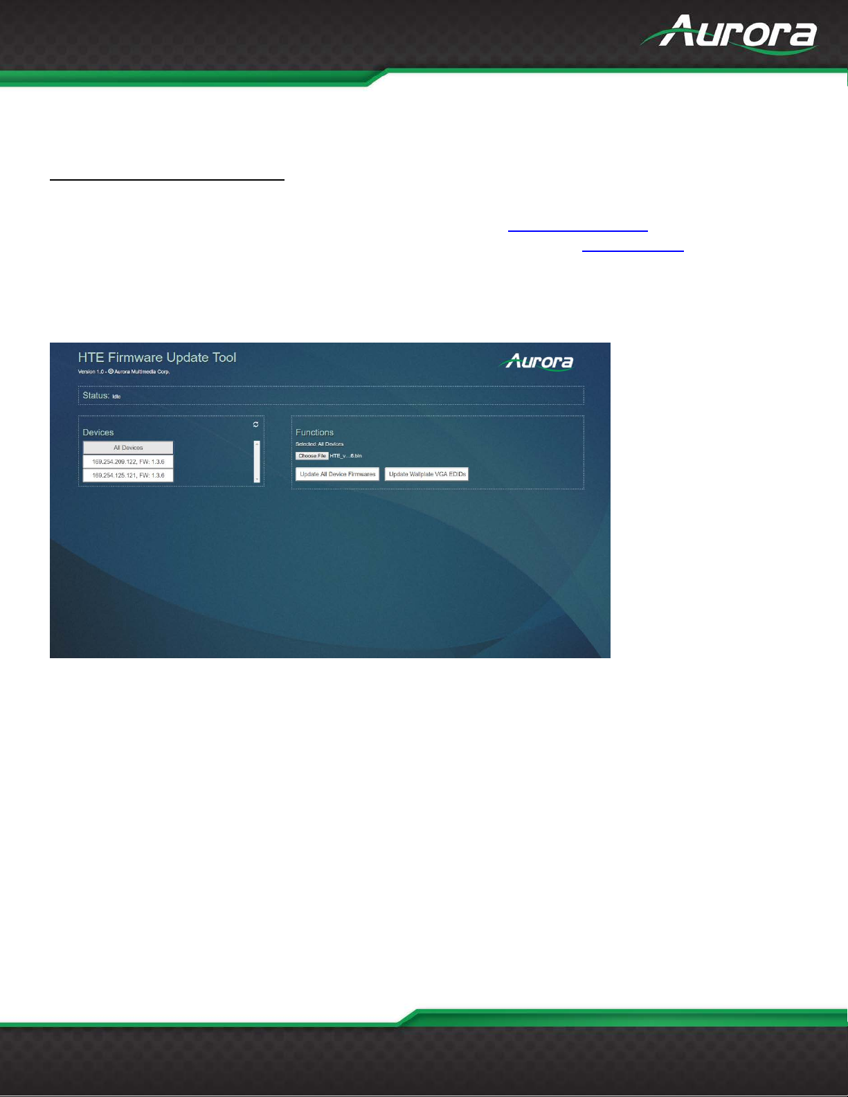
USERS GUIDE
www.auroramm.com
49
APPENDIX 2 Firmware Update
HT Series Firmware Update Tool
HT Update Tool can be downloaded from the Aurora portal on www.auroramm.com
extract and run the "htefwtool.exe" file. It'll open a window and tell you to go to 127.0.0.1:3002 on your browser
(port 3002). You will be able to update all units or individually. It can also apply EDID updates to VGA on HTW
wall plate devices.
. Once downloaded,
Important! Make sure not to close the console window or browser in the middle of updating. For a large
number of devices, it may take several minutes to complete.
Page 51
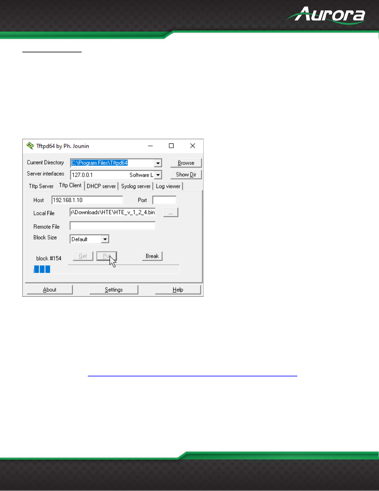
USERS GUIDE
www.auroramm.com
50
TFTP Tool Method
The HT Series device can be put to bootloader mode in one of the following ways:
• Press and hold the FUNC button when the board is powered on.
• Issue !**WSUPDATE<cr> command via serial port. !** is !20 for TX /HTW and !30 for RX.
• Select ‘Start Update’ from the device’s webpage.
• Issue the ‘EnterUpdateMode’ RPC command.
Once in update mode, TFTP the firmware
Enter the IP address of the unit into the 'Host' field and select the firmware file (HTE_v_#_#_#.bin) from the 'Local File'
field in the 'Tftp Client' tab of TFTPd. Please wait about 10 seconds after entering firmware update mode before clicking
'Put'. If the update does not start immediately, click 'Break' and then 'Put' again. If you do not know the IP address of the
unit, plug in a serial cable and the IP address will appear in your terminal at baud rate 115200 upon entering firmware
update mode.
Link to TFTPd program: https://bitbucket.org/phjounin/tftpd64/downloads/Tftpd64-4.64-setup.exe
Page 52
USERS GUIDE
www.auroramm.com
51
525p@60
640x480@60
1152x864@75
625p@50
640x350@70
1280x768@60
720p@60
640x350@85
1280x800@60
720p@50
1280x960@60
720p@24
640x480@75
1280x960@85
720p@25
640x480@85
720p@30
720x400@70
1080i@60
720x400@85
1080i@50
1360*768@60
1080i@100
1440x900@60
1080p@60
1400x1050@60
1080p@50
800x600@75
1600x1200@60
1080p@30
1680x1050@60
848x480@60
1920x1200@60
1080p@24
1024x768@43
1080p@25
1024x768@60
1024x768@85
APPENDIX 3 VGA Supported Timing
Page 53
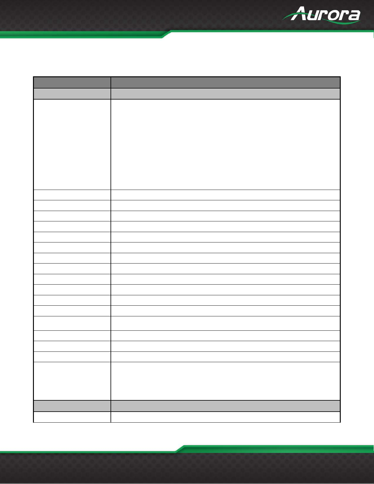
USERS GUIDE
www.auroramm.com
52
328ft 100m – 1080p 60Hz 24 & 36bit CAT 5e/6/6a/7
Receiver: 3.5mm TRS Signal- TIP, 5V- Ring, GND- Sleeve
Transmitter: 3.5mm TS Signal- TIP, GND- Sleeve
Internal
ReAX Option: IPE-ReAX-1
APPENDIX 4
Technical Specifications
Model Name HT Series
Technical HTE-TX2/RX2
328ft 100m – 1080p 60Hz 48bit CAT 6a/7
328ft 100m – 4k2k 60Hz 4:4:4 CAT 6a/7
Distance
CAT 5e/6 will achieve 328ft 100m for pixel clock <=225MHz
CAT 5e/6 will achieve 230ft 70m for pixel clock >225MHz
CAT 6a/7 will achieve 328ft 100m for pixel clock >225MHz
Max Resolution 4K60 4:4:4
Color Depth 24bit 5e/6/6a/7, 36bit 5e/6, 48bit 5e/6/6a/7
RS-232 300 – 115kbps
IR without LXC 30K-60KHz
LAN 2 – 1Gbps local, 10/100 over HDBaseT Link
LAN POE+ Port 1 PoE+
HDMI 3D, HDCP 2.2 Compliant
Front LED Status Power, Status, HDMI, HDBaseT, RS-232 TX/RX, IR In/Out, USB Host/Device
Front Selections Function & Select
LAN Connectors Dual RJ-45 8P8C with 2 LED indicators each
HDBaseT Connector RJ-45 WE/SS 8P8C
RS-232 Connector 3.5mm TRS TX- TIP, RX- Ring, GND- Sleeve
IR Connector
HDMI Connector Type A 19 pin
Audio Connectors
Power Connector
Option Slot
Mechanical HTE Units
Housing Black Aluminum Enclosure
5 Pin 3.81mm Euro Line In/ Line Out
2 pin 3.81mm Euro
Dante/AES67 Option: IPE-DTE-1 (2 Ch), IPE-DTE-2 (8 Ch)
Page 54
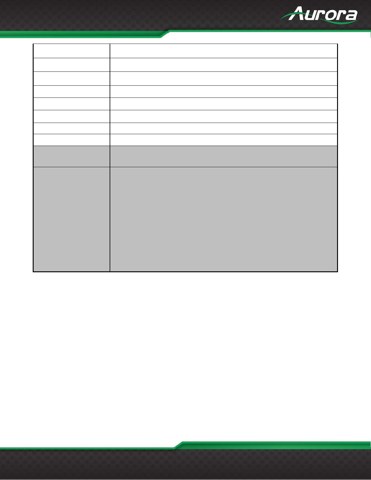
USERS GUIDE
www.auroramm.com
53
Dimensions
[L x W x H]
1x HTE-TX2
2 x Wall / Desk Mount Ears with Screws
IR Receiver 30K-60KHz (CA0062-1)
151.13mm x 90.17mm x 29.21mm [5.95" x 3.55" x 1.15"]
Weight .628lbs [284.856kg] TX & RX
Mounting Wall-mounting and Rack Mounting
Power Supply 48VDC (Only 1 required on either TX or RX)
Power Consumption 7 Watts (TX), 8 Watts (Rx) No USB/ 12.9 Watts with USB [max]
Operation Temperature
Storage Temperature
Relative Humidity 20~90% RH [no condensation]
Package Contents
0~40°C [32~104°F]
-20~60°C [-4~140°F]
1x HTE-RX2
IR Emitter (CA0061-1)
PS0094-2 48v DC 25 Watt Power Supply
Options
PS0081-1 48V PoE+ 25 Watt Power Supply
IPE-DTE-1 Dante/AES67 2 Channel
IPE-DTE-2 Dante/AES67 8 Channel
IPE-ReAX-1 ReAX IP Control Card
*Note: Specifications subject to change without no tice.
Page 55
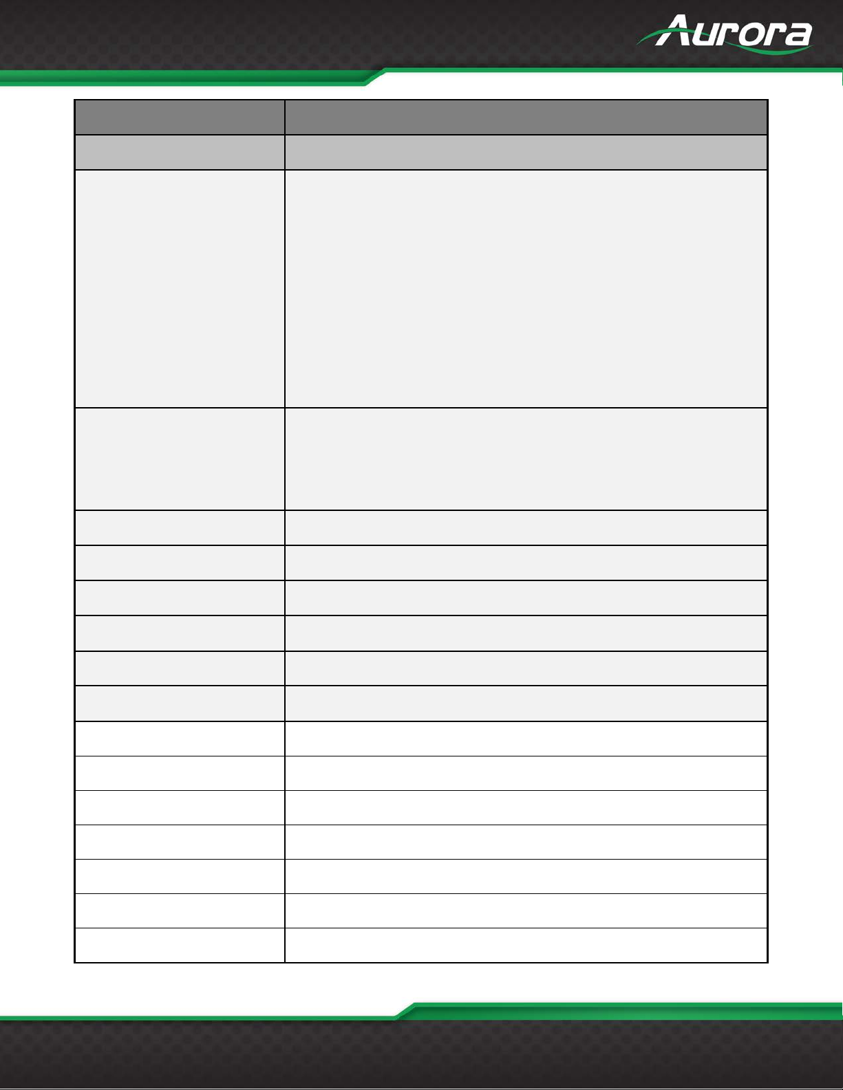
USERS GUIDE
www.auroramm.com
54
Model Name
HTW-2
Technical
HTW-2 Wall Plate
328ft 100m – 1080p 60Hz 24 & 36bit CAT 5e/6/6a/7
1080p 60Hz
Color Depth
24bit 5e/6/6a/7, 36bit 5e/6, 48bit 5e/6/6a/7
RS-232
300 - 115kbps
IR Window
30kHz-60Khz
LAN
10/100
HDMI
3D, HDCP 2.2 Compliant
Front Selections
3 Backlit Buttons (Red, Green, Blue)
LAN Connectors
Front RJ-45 with 2 LED indicators (Only y ello w LED is ac tive)
HDBaseT Connector
Rear RJ-45 WE/SS 8P8C
RS-232 Connector
4 pin 3.81mm Euro Rear
HDMI Connector
Two Type A 19 pin
VGA Connector
15 Pin High Density
Audio Connectors
3.5mm Line In/Line Out
Power Connector
2 pin 3.81mm Euro
328ft 100m – 1080p 60Hz 48bit CAT 6a/7
328ft 100m – 4k2k 60Hz 4:4:4 CAT 6a/7
Video Distance (HDBaseT)
Max Resolution
CAT 5e/6 will achieve 328ft 100m for pixel clock <=225MHz
CAT 5e/6 will achieve 230ft 70m for pixel clock >225MHz
CAT 6a/7 will achieve 328ft 100m for pixel clock >225MHz
1920 x 1200 @ 60Hz
4k x 2k @ 60Hz 4:4:4
Page 56
USERS GUIDE
www.auroramm.com
55
Dante/AES67 Option: IPE-DTE-1 (2 Ch), IPE-DTE-2 (8 Ch)
Mechanical
HTW-2
Housing
Aluminum front with aluminum rear enclosure
Dimensions
Weight
1.13g [2.5lbs]
Mounting
Wall-mounting Decora® 2 Gang
Power supply
48V DC
8 Watts without USB
Operation temperature
0~40°C [32~104°F]
Storage temperature
-20~60°C [-4~140°F]
Relative humidity
20~90% RH [no condensation]
1x HTW-2
PS0094-2 48v DC 25 Watt Power Supply
Option Slot
[L x W x D]
Power consumption
ReAX Option: IPE-ReAX-1
3.728” x 2.83” (4.331” with tabs) x 1.404”
12.9 Watts with USB
Package Contents
Options
Specifications subject to change without notice.
1x Paintable White Wall Plate
1x User Manual
PS0081-1 48V PoE+ 25 Watt Power Supply
IPE-DTE-1 Dante/AES67 2 Channel
IPE-DTE-2 Dante/AES67 8 Channel
IPE-ReAX-1 ReAX IP Control Card
Page 57
USERS GUIDE
www.auroramm.com
56
APPENDIX 5
Cabling
Aurora extender products have been tested utilizing shielded cabling. Although our products will work fine
without shielded cable it is highly recommended for environmental reasons as the signals are high frequency
and can radiate as well as be susceptible to external frequencies and possibly cause noise or disruption in the
image. Unshielded cabling will work fine in a conduit as it will provide the shielding. We have found not all
cable is created equal even though they appear similar. This can affect distance and overall performance.
Below is a list of cables that have been officially tested with our products by the manufacturer of the cable.
West Penn Wire
CAT 6 Shielded - HDBaseT Certified - Only in Black
4246F – CMR, 254246F – CMP (Plenum)
CAT 6a Shielded HDBaseT Certified - Only in Black
4246AF – CMR, 254246AF – CMP (Plenum)
Both CAT 6 and CAT 6a Shielded Cables utilized a Modular Plug Kit:
90170-BI - Includes: 100 Connectors, 100 Boots, Crimp Tool, External round Crimp Tool, Strip Tool
CAT 6 Unshielded - Colors
4246 – CMR, 254246 - CMP (Plenum)
Connector: 32-6EZP
CAT5e Shielded - Blue or Gray
4245F – CMR, 254245F - CMP (Plenum)
Connector: 32-EZSTP
CAT 5e Unshielded- 12 Colors
4245-CMR, 254245 - CMP (Plenum)
Connectors: 32-EZP
Page 58
USERS GUIDE
www.auroramm.com
57
APPENDIX 6
Warranty
Limited 5 Year Warranty
Aurora Multimedia Corporation (“Manufacturer”) warrants that this product is free of defects in both materials and
workmanship for a per iod of 5 years as d efined herein for par ts and labor from date of purchase. T his Limited Warr anty
covers products purchased in the year of 2019 and after. Motorized mechanical parts (Hard Drives, DVD, etc.),
mechanical parts (but tons, doors, etc .), rem otes a nd c ables ar e cover ed for a per iod of 1 year. T ouc h screen displ ays ar e
covered for 1 year; t ouch sc reen overlay compone nts are c overed for 90 days. Supplie d batter ies are not c over ed by this
warranty. During the warranty peri od, and upon pr oof of purch ase, the produc t will be re paired or repl aced (with same or
similar model) at our option without charge for parts or labor for the specified product lifetime warranty period.
This warranty shall not apply if any of the following:
A. The product has been damaged by negligence, accident, lightning, water, act-of-God or mishandling; or,
B. The product has not been operated in accordance with procedures specified in operating instructions: or,
C. The product has been repaired and or altered by other than manufacturer or authorized service center; or,
D. The product's original serial number has been modified or removed; or,
E. External equipme nt other than supplied by manufacturer, in deter mination of manufacturer, shall have aff ected the
performance, safety or reliability of the product; or,
F. Part(s) are no longer available for product.
In the event that the produc t needs r epair or replac ement dur ing the s pecif ied wa rranty period, pr oduct s hould be s hippe d
back to Manufactur er at Purchaser' s expense. Repai red or replaced pro duct shall be ret urned to Purchas er by standard
shipping methods at Manu facturer's discretion. Express shipping will be at the expens e of the Purchaser. If Purc haser
resides outside the contiguous US, return shipping shall be at Purchaser's expense.
No other warranty, express or implied other than Manufacturer's shall apply.
Manufacturer does n ot assume any respo nsibility for consequenti al damages, expenses or loss of revenue or property,
inconvenience or interr upti on in operat ion ex perienc ed by the customer due to a malfunc tion of t he purch ased equ ipmen t.
No warranty service per formed on any product shal l extend the app licable warra nty period. Th is warranty d oes not cover
damage to the equipm ent during shipping and Manufacturer as sumes no responsibility for such dama ge. This product
warranty extends to the original purchaser only and will be null and void upon any assignment or transfer.
Page 59
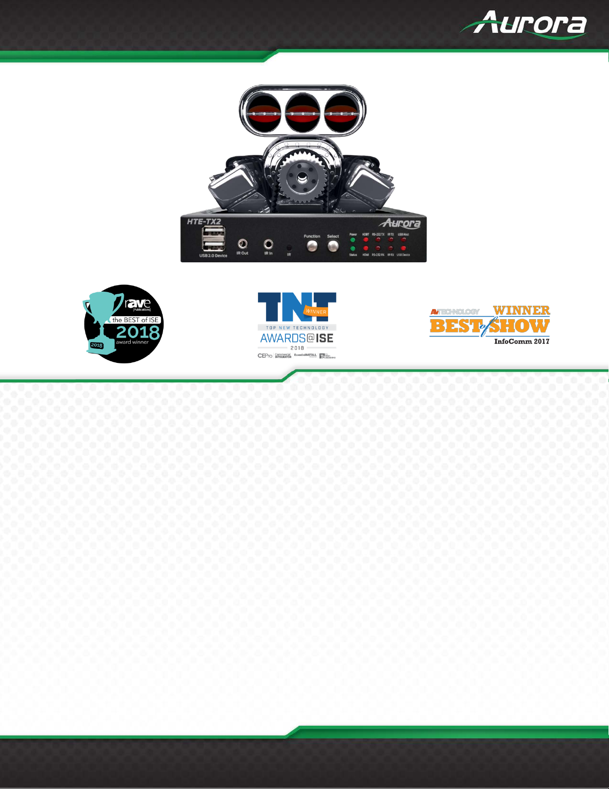
www.auroramm.com
58
USERS GUIDE
Aurora Multimedia Corporation
205 Commercial Court | Morganville, NJ 07751
Phone: 732-591-5800 | Fax: 732-591-6801
 Loading...