

Page 1
USERS GUIDE
Manual Number: 170410 | Firmware Rev. v0.7 & Above
www.auroramm.com
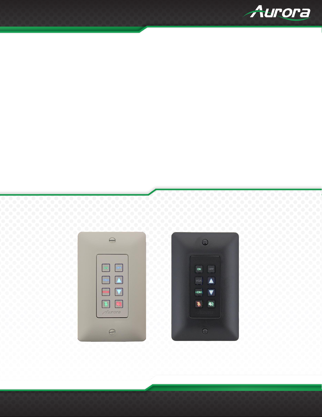
DXB-8
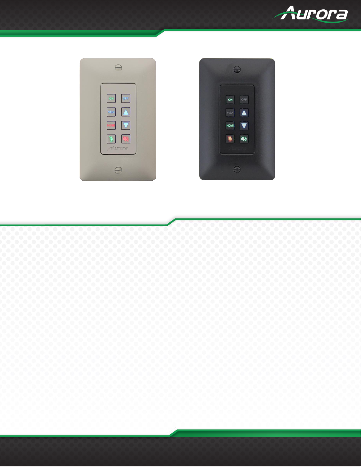
1 Gang Decora® 8 Button Wall Plate Controller
Page 2
USERS GUIDE
www.auroramm.com
ii
The lightning symbol in the triangle is used to alert you to the presence of dangerous voltage inside the product
that may be sufficient to constitute a risk of electric shock to anyone opening the case. It is also used to indicate
improper installation or handling of the product that could damage the electrical system in the product or in other
equipment attached to the product.
The exclamation point in the triangle is used to alert you to important operating and maintenance instructions.
Failure to follow these instructions could result in injury to you or damage to the product.
Be careful with electricity:
Power Outlet: To prevent electric shock, be sure the electrical plug used on the product power cord
matches the electrical outlet used to supply power to the Aurora product. Use the power adapter and power
connection cables designed for this unit.
Power Cord: Be sure the power cord is routed so that it will not be stepped on or pinched by heavy items.
Lightning: For protection from lightning or when the product is left unattended for a long period, disconnect
it from the power source.
Also follow these precautions:
Ventilation: Do not block ventilation slots, if applicable, on the product, or place any heavy object on top of
it. Blocking airflow could cause damage. Arrange components so that air can flow freely. Ensure that there
is adequate ventilation if the product is placed in a stand or cabinet. Put the product in a properly ventilated
area, away from direct sunlight or any source of heat.
Overheating: Avoid stacking the Aurora product on top of a hot component, such as a power amplifier.
Risk of Fire: Do not place unit on top of any easily combustible material, such as carpet or fabric.
Proper Connections: Be sure all cables and equipment are connected to the unit as described in this
manual.
Object Entry: To avoid electric shock, never stick anything in the slots on the case, or remove the cover.
Water Exposure: To reduce the risk of fire or electric shock, do not expose to rain or moisture.
Cleaning: Do not use liquid or aerosol cleaners to clean this unit. Always unplug the power to the device
before cleaning.
ESD: Handle this unit with proper ESC care. Failure to do so can result in failure.
SAFETY INSTRUCTIONS
Please review the following safety precautions. If this is the first time using this model, then read this manual before
installing or using the product. If the product is not functioning properly, please contact your local dealer or Aurora for
further instructions.
FCC
This device complies with Part 15 of the FCC Rules. Operation is subject to the following two (2) conditions:
1. This device may not cause harmful interference.
2. This device must accept any interference received, including interference that may cause undesired operation.
Trademarks
All trademarks in this document are the properties of their respective owners.
Page 3
USERS GUIDE
www.auroramm.com
ii
TABLE OF CONTENTS
PACKAGE CONTENTS ......................................................................................................................................................... 3
INTRODUCTION ..................................................................................................................................................................... 4
About ................................................................................................................................................................................... 4
Features .............................................................................................................................................................................. 4
DXB-8 Front ........................................................................................................................................................................ 5
DXB-8 Rear ......................................................................................................................................................................... 6
APPLICATION ........................................................................................................................................................................ 7
DXB-8 Controlling DXW-2EU and Projector ....................................................................................................................... 7
BUTTON SETUP FUNCTIONS .............................................................................................................................................. 8
Button Setup........................................................................................................................................................................ 8
DXB-8 Daisy Chain Mode ................................................................................................................................................... 9
PROGRAMMING SOFTWARE ............................................................................................................................................ 10
DX Interface ...................................................................................................................................................................... 10
BUTTON CAP SELECTION ................................................................................................................................................. 11
Button Caps....................................................................................................................................................................... 11
SERIAL COMMANDS .......................................................................................................................................................... 12
RS-232 Commands ........................................................................................................................................................... 12
RS-232 Command Usage ................................................................................................................................................. 16
APPENDIX 1 ......................................................................................................................................................................... 17
Troubleshooting ................................................................................................................................................................ 17
APPENDIX 2 ......................................................................................................................................................................... 18
Firmware Update ............................................................................................................................................................... 18
APPENDIX 3 ......................................................................................................................................................................... 19
Technical Specifications .................................................................................................................................................... 19
APPENDIX 4 ......................................................................................................................................................................... 20
Warranty ............................................................................................................................................................................ 20
Page 4
USERS GUIDE
www.auroramm.com
3
PACKAGE CONTENTS
Please make sure the following items are included within your package. Contact your dealer if any items are missing or
damaged.
DXB-8 x 1
Gang Decora
*Note: Go to www.auroramm.com for latest manual and firmware.
®
Paintable White Wall Plate x 1
Page 5
USERS GUIDE
www.auroramm.com
4
8 Backlit Buttons (Red, Green, Blue)
Fits in Standard 1 Gang Decora® Style Outlet
2 RS-232 Ports
Buttons Individually Programmable for RS-232 Command
Programmable on Press, Release, Toggle, and Hold
Macro Functions and Interlocking Buttons
9600 – 115k Baud Rate Selectable
Designed to Work seamlessly with DXW-2 Series
Customizable Laser Etched Buttons
Daisy Chain up to 8 Units for Multi-Gang Button Panels
Low Power
5v DC Powered
*Note: SN >= SNA1618-0072 allows 5-24vdc operation.
Low Depth 48” for Floor and Table Boxes
INTRODUCTION
About
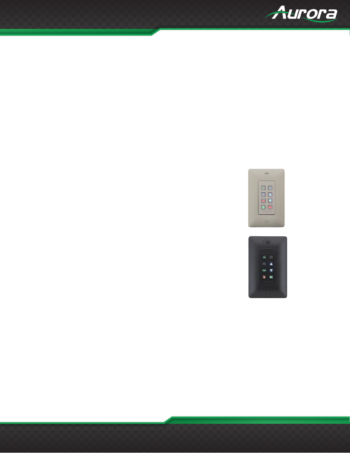
The DXB-8 is a low cost 8 button single gang button panel. Designed to work with just about any RS-232 device on the
market, the DXB-8 allows any RS-232 string to be assigned to the press and release of each button. Advanced
functionality is available like repeat on hold. Toggle, macro (delay between multiple commands), and interlocking buttons
for transport controls, power on/off, etc.
The buttons can individually be lit red, green, or blue so in dimly lit areas it can be seen. There are over 60 different laser
etched button types available as well as custom laser etching. Available in Decora® white or black, the DXB-8 is designed
to match.
Low cost, low power, simplicity, and compatibility with just about any device on the market makes the DXB-8 the simple
sweet solution of choice.
Features
Page 6
USERS GUIDE
www.auroramm.com
5
DXB-8 Front
Front
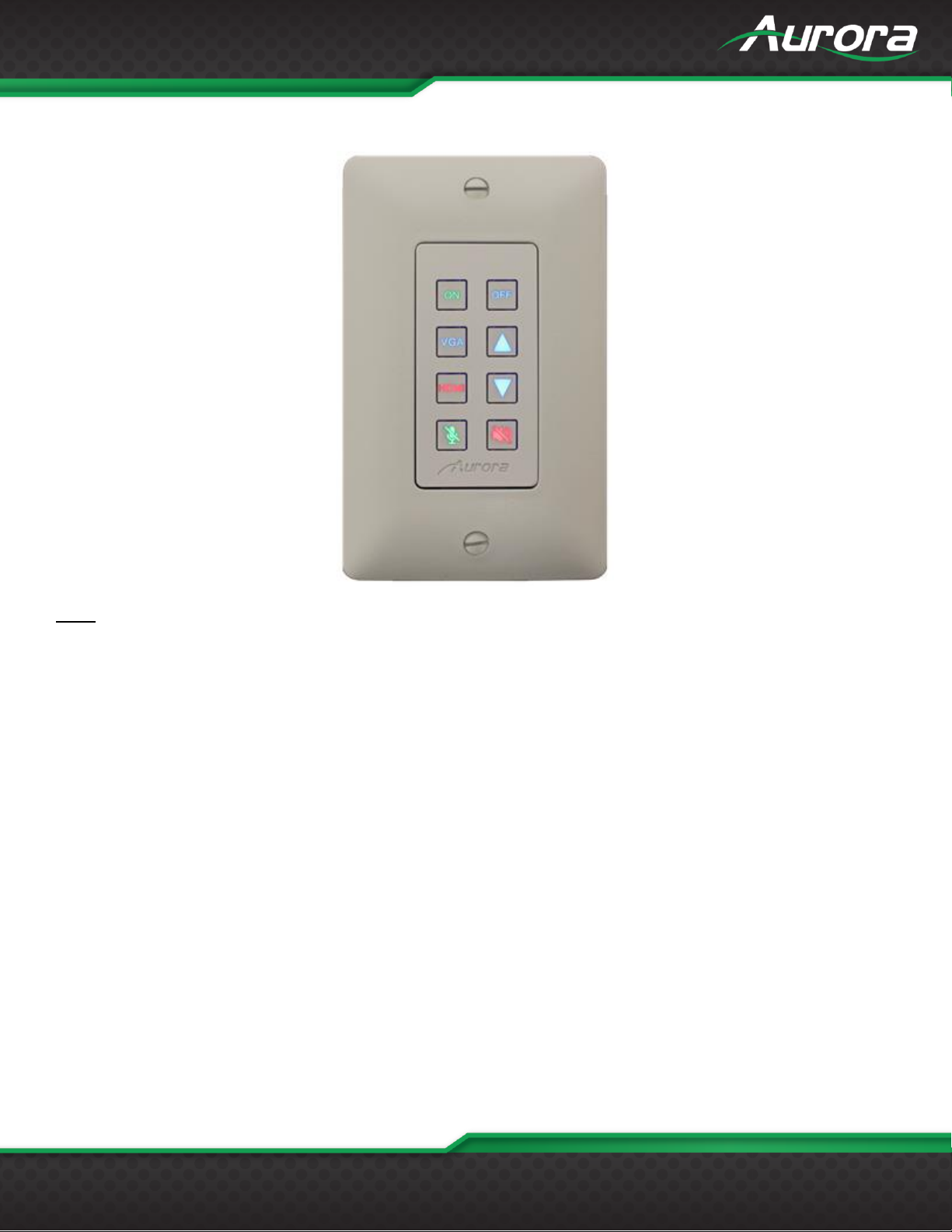
Buttons: There are 8 backlit buttons, ON, OFF, VGA, HDMI, Up Arrow, Down Arrow, Speaker Mute, and Mic Mute.
These laser etched buttons come as a default with the DXB-8. Other customizable buttons are available. The LED
backlighting can be set to light red, green, or blue.
The default scheme is to match the DXW-2 wall plate series to remotely select the inputs and to also control the display.
Page 7
USERS GUIDE
www.auroramm.com
6
DXB-8 Rear
Rear Connections
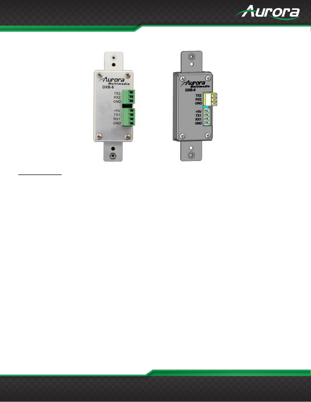
RS-232 1: Connect RS-232 device up to 115k baud. Note there is a 5v line as it is designed to power the DXB-8 from
the DXW-2 wall plate or an option 5v supply for stand-alone operation with any RS-232 device.
RS-232 2: Connect RS-232 device up to 115k baud.
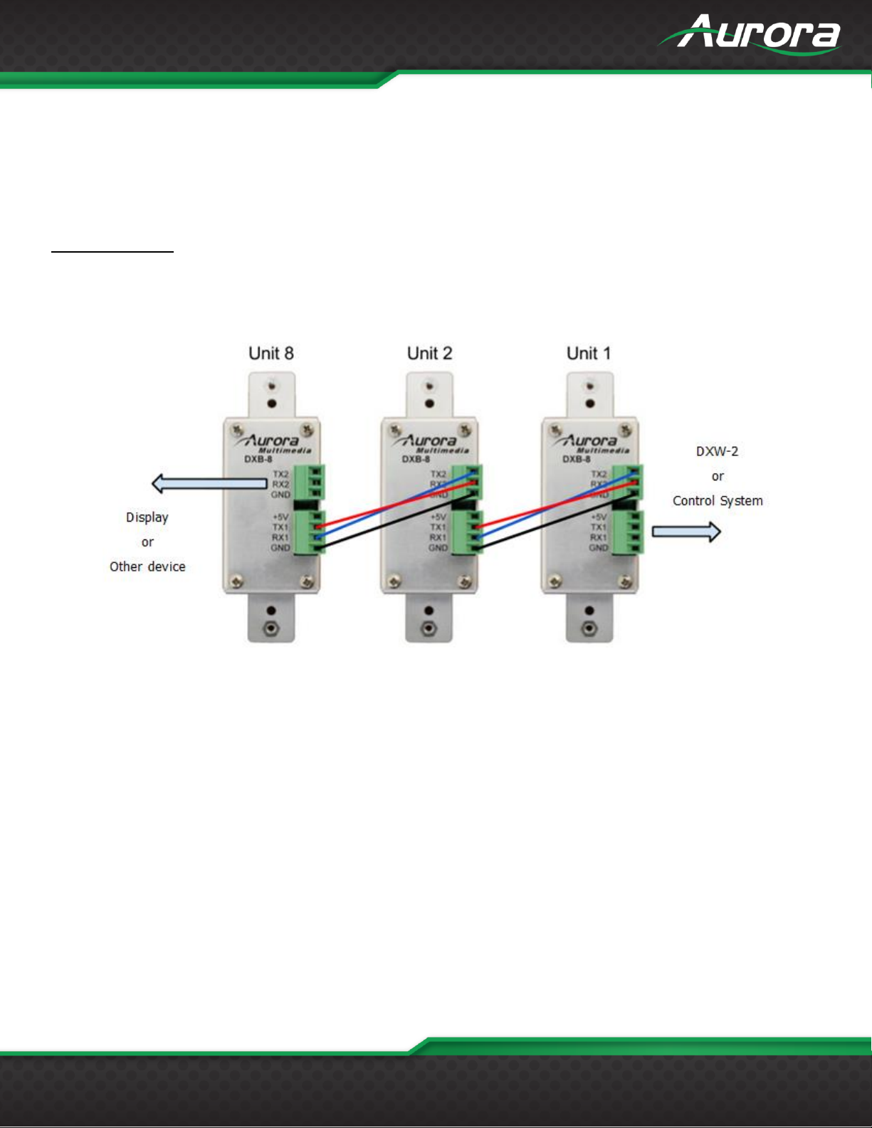
Units can be linked together to create larger button arrays by feeding port 2 of first unit into port 1 of next unit in line. By
repeating this process from unit to unit, the commands can pass through from one the next. Make certain to “null” the TX
and RX. In other words TX should go to RX and RX should go to TX from unit to unit. The RS-232 protocol is designed to
communicate to the address of a specific unit so it is important to make certain each unit has a unique address and the
same baud rate.
Page 8
USERS GUIDE
www.auroramm.com
7
APPLICATION
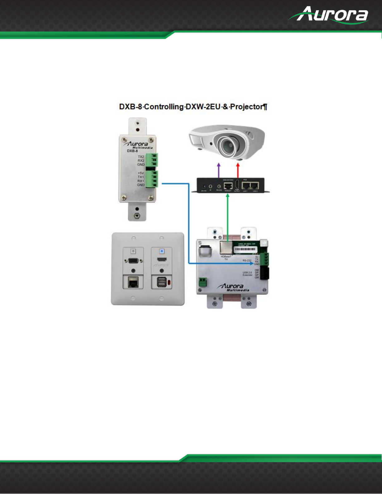
DXB-8 Controlling DXW-2EU and Projector
The example below demonstrates the DXB controlling a DXW-2 series wall plate which in turn passes the RS-232 to the
DXE-CAT series receiver. The DXE-CAT receiver RS-232 port is connected to the projector.
Page 9
USERS GUIDE
www.auroramm.com
8
BUTTON SETUP FUNCTIONS
Button Setup
Buttons are referenced 1-8 starting in upper left to lower left for 1-4 and upper right to lower right for 5-8.
Unit Address: Holding buttons 1 and 4 down for 5 seconds will allow user to press button 1 through 8 to set address
accordingly. When the 5 seconds is reached, current address will show by blinking button relative to address blue.
Next user will press any of the 8 buttons to set new address. Once button is pressed, a confirmation will happen by
flashing new address buttons LED RED, then green then off as it exits the mode of operation.
Factory Test: Holding buttons 5 and 8 down for 5 seconds will do factory test. Factory test is light all buttons Red for
2 seconds, Blue for 2 seconds, and Green for 2 seconds. Next, it will blink a red LED starting at button 1. When
pressed, next button in order will blink red and prior button will turn off until all 8 buttons are pressed. After button 8 is
pressed, unit will finish with RS-232 loop test from port 1 to port 2 to verify back and forth communications. LED 1 and
2 will light blue and pressing button 1 will send string from port 1 to 2 and pressing button 2 will send string from port 2
to 1. During both, it checks for proper response. Send string !test<cr> to be responded with ~test<cr>. If it checks
okay, LED 4 will light Green for okay or Red for bad for port 1. Use LED 5 for port 2 indicator. Once Port 2 test is
done, light blue LED 8 and when pressed End factory test mode by turning on all 8 LEDs blue for 1 sec then off.
Factory Reset: Holding buttons 3 and 4 down for 10 seconds will do a factory reset. Factory reset will set RS-232
ports 1 and 2 to 96008N1, Unit address to 1, and assign strings on push for !1B1<cr> for button 1 and increment
accordingly for all 8 button. The release will be set to !1R1<cr> for button 1 and increment accordingly for all 8
buttons. Hold will have nothing. All LED will be defaulted to blue for press and release.
Update Mode Port 1: Holding buttons 1 & 8 > 5 seconds will force unit into firmware update mode via port 1.
Update Mode Port 2: Holding buttons 4 and 5 > 5 seconds will force unit into firmware update mode via port 2.
Daisy Chain Mode: Holding buttons 4 and 8 for 2 seconds will enable daisy chain mode. After 2 seconds, all button
LEDs will go off for 1 second then LEDs 1, 4, 5 and 8 will light for 1 second, Red for daisy chain mode or Green for
normal mode then all LEDs return to their normal color.
Page 10
USERS GUIDE
www.auroramm.com
9
DXB-8 Daisy Chain Mode
The DXB-8 units can be combined (up to 8 total), allowing multiple units to function as a single control interface. All
commands when operated in this mode pass through to com1 of unit1. The last unit in the chain must always be address
8 in order to connect a device to communicate with port 2. The !8PD,z<cr> (z = string) command must be used to target a
command out this port (see RS-232 command section for proper usage). If you are not using the last port in the chain
then it will not be necessary.
Daisy Chain Mode
Holding buttons 4 and 8 for 2 seconds will enable daisy chain mode. After 2 seconds, all button LEDs will go off for 1
second then LEDs 1, 4, 5,and 8 will light for 1 second, Red for daisy chain mode or Green for normal mode then all LEDs
return to their normal color.
Page 11
USERS GUIDE
www.auroramm.com
10
PROGRAMMING SOFTWARE
DX Interface
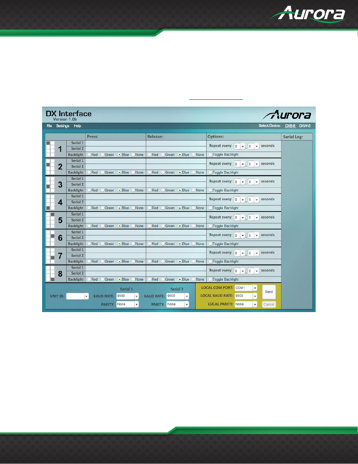
DX Interface is a free utility for programming the buttons with the various functions. It allows a user to assign RS-232
strings and LED color selection to the different button states. These assignments can be applied to the push, release, and
holding of the buttons. Refer to Appendix 2 for cable connection to a PC. DX Interface is designed to run on a Windows®
PC. The latest versions of DX Interface can be downloaded from www.auroramm.com.
Page 12
USERS GUIDE
www.auroramm.com
11
BUTTON CAP SELECTION
Button Caps
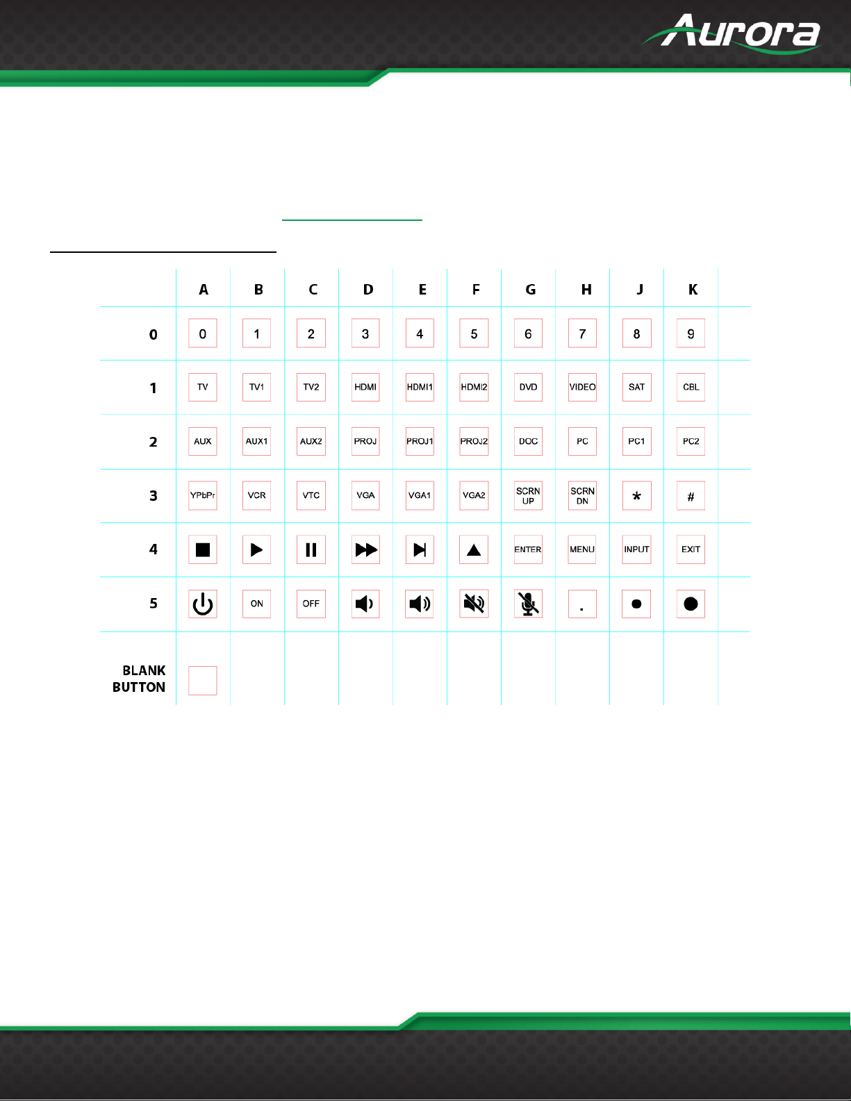
The DXB-8 buttons are removable and can be replaced with a variety of buttons listed on the chart below in white or
black. For caps not listed on the chart custom laser etched button caps are available for a one time processing fee to
accommodate any install. Check with [email protected] for more information.
DXB-8 Button Cap Selection Chart
Buttons can be reversed 180o.
*Note: Part Number = DXB-C[Row#][Column Letter]-B/W (B = Black / W = White)
4B = Play, Left, and Right, 4D = Fast Forward & Rewind, 4E= Next and Prev 4F = Up & Down
Blank button (No LED backlight) Part Number = DXB-CB-B/W (B = Black / W = White)
Example: White PROJ Button PN# = DXB-C2D-W.
Page 13
USERS GUIDE
www.auroramm.com
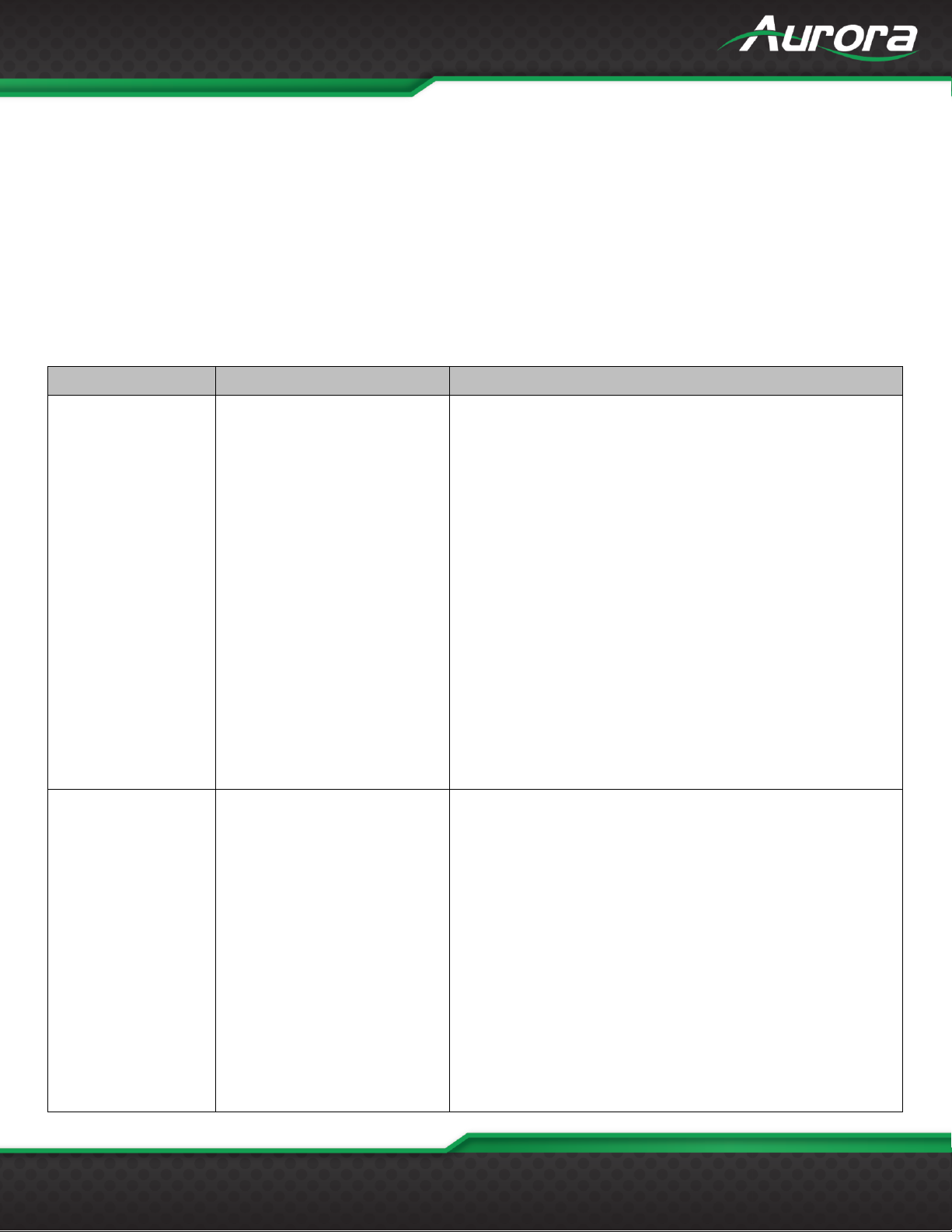
12
!
Command
?
Query
~
Response
<cr>
0x0D Hex/13 Decimal (Do not confuse with delimiter %0D)
Command
String Format
Information
Button Push String
(99 Bytes Max)
!xPSy,b,z<cr>
x = Unit address = 0-8 Address Zero is received by all but no
response from units. Response only when set to address 1-8.
Factory default is address 1.
y = Port Number 1 or 2
b = Button Number 1 - 8
z = string is in ASCII and can have non-printable as ASCII
characters as well. To send non-printable ASCII (Hexadecimal)
use a % in front of the 2 ASCII digits. To send “%” then use
%%. Example: Line Feed = 0x0A Hex will be %0A
Delay Delimiter - # is used with a single digit after for delays
between commands in a string to create a “Macro”. A 0-9 will
follow the #. Each number is a multiple of 100ms delay so #8 is
800ms. If # character is require to be sent for none delay
purpose then a ## must be used.
!1PS1,1,Hello string 1%0D#5Hello string 2%0D<cr>
Pressing button 1 will send on serial port 1:
Hello string 1<cr>
Delay 500ms
Hello string 2 <cr>
Button Release
String
(99 Bytes Max)
!xRSy,b,z<cr>
x = Unit address = 0-8 Address Zero is received by all but no
response from units. Response only when set to address 1-8.
Factory default is address 1.
y = Port Number 1 or 2
b = Button Number 1 - 8
z = string is in ASCII and can have non-printable as ASCII
characters as well. To send non-printable ASCII (Hexadecimal)
use a % in front of the 2 ASCII digits. To send “%” then use
%%. Example: Line Feed = 0x0A Hex will be %0A
Delay Delimiter - # is used with a single digit after for delays
between commands in a string to create a “Macro”. A 0-9 will
follow the #. Each number is a multiple of 100ms delay so #8 is
800ms. If # character is require to be sent for none delay
purpose then a ## must be used.
!1RS1,1,Hello string 1%0D#5Hello string 2%0D<cr>
SERIAL COMMANDS
RS-232 Commands
Page 14
USERS GUIDE
www.auroramm.com
13
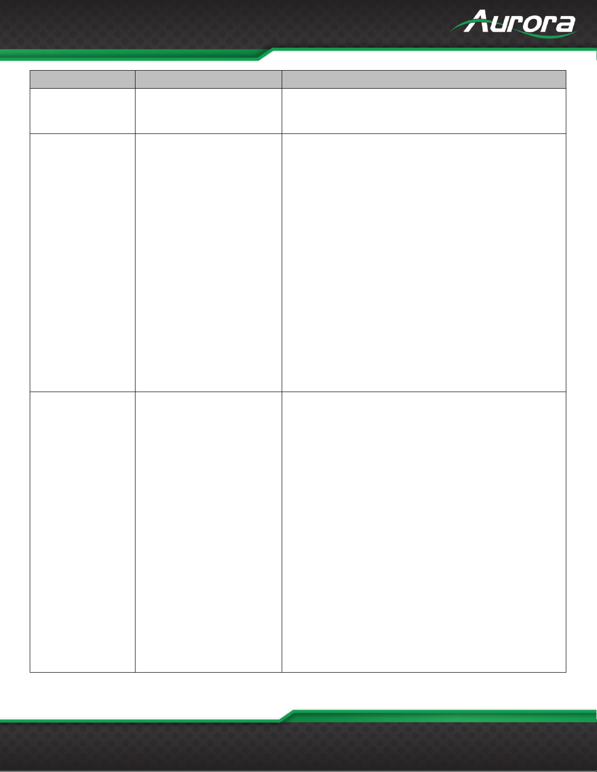
Command
String Format
Information
Releasing button 1 will send on serial port 1:
Hello string 1<cr>
Delay 500ms
Hello string 2 <cr>
Hold String
!xHSy,b,tt,z<cr>
x = Unit address = 0-8 Address Zero is received by all but no
response from units. Response only when set to address 1-8.
Factory default is address 1.
y = Port Number 1 or 2
b = Button Number 1 - 8
tt = repeat timing. First digit is seconds, second digit is tenths.
z = string is in ASCII and can have non-printable as ASCII
characters as well. To send non-printable ASCII (Hexadecimal)
use a % in front of the 2 ASCII digits. To send “%” then use
%%. Example: Line Feed = 0x0A Hex will be %0A
Delay Delimiter - # is used with a single digit after for delays
between commands in a string to create a “Macro”. A 0-9 will
follow the #. Each number is a multiple of 100ms delay so #8 is
800ms. If # character is require to be sent for none delay
purpose then a ## must be used.
!1HS1,1,03,Hello string 1%0D#5Hello string 2%0D<cr>
Holding button 1 will send on serial port 1 every 300ms:
Hello string 1<cr>
Delay 500ms
Hello string 2 <cr>
Toggle String
!xTGy,b,i,l,z<cr>
x = Unit address = 0-8 Address Zero is received by all but no
response from units. Response only when set to address 1-8.
Factory default is address 1.
y = Port Number 1 or 2
b = Button Number 1 - 8
i = Instance Number 1 or 2
l = LED Color R, G, B, N (R = Red, G = Green, B = Blue, N =
None)
z = string is in ASCII and can have non-printable as ASCII
characters as well. To send non-printable ASCII (Hexadecimal)
use a % in front of the 2 ASCII digits. To send “%” then use
%%. Example: Line Feed = 0x0A Hex will be %0A
Delay Delimiter - # is used with a single digit after for delays
between commands in a string to create a “Macro”. A 0-9 will
follow the #. Each number is a multiple of 100ms delay so #8 is
800ms. If # character is require to be sent for none delay
purpose then a ## must be used.
!1TG1,1,2,R,Hello string 1%0D#5Hello string 2%0D<cr>
Pressing button 1 will send on serial port 1:
Hello string 1<cr>
Delay 500ms
Hello string 2 <cr>
Page 15
USERS GUIDE
www.auroramm.com
14
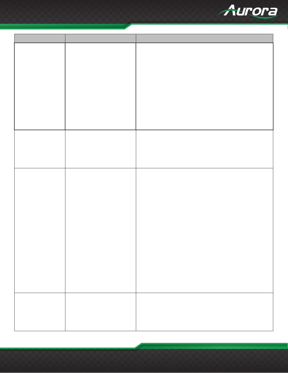
Command
String Format
Information
Button Command
String
(99 Bytes Max)
!xCSy,z<cr>
x = Unit address = 0-8 Address Zero is received by all but no
response from units. Response only when set to address 1-8.
Factory default is address 1.
y = Button Number 1 - 8
z = Command string is in ASCII to be executed when a button
is pressed. Can be any valid serial command with the Unit
address set to 0. (Commands start with a '!') Best command to
use with this feature is the Button LED Setup (All) command as
it allows one button to effect the status of the other buttons for
an interlocking effect.
Button 1 telling other buttons new LED states when pressed. In
this example button 1 would turn green while button 2 turns
red. Great for Power on/off interlocking button effect or
transport controls for a DVD player, etc.
!0CS1,!0BA,G,R,R,N,N,N,N,N,N,N,N,N,N,N,N,N<cr>
Setup Volume / Cmd
Preset Buttons
!xVBy,b,c,tt <cr>
x = Unit address = 0-8 Address Zero is received by all but no
response from units. Response only when set to address 1-8.
Factory default is address 1.
y = Port Number 1 or 2
b = Button Number 1 - 8 for Volume up
c = Button Number 1 - 8 for Volume down
tt = repeat timing. First digit is seconds, second digit is tenths.
Setup
Volume / Cmd
Presets
!xVS,s1,s2,s3,s4,s5,s6,s7,s8,s
9,s10,s11,s12<cr>
x = Unit address = 0-8 Address Zero is received by all but no
response from units. Response only when set to address 1-8.
Factory default is address 1.
s1 – s12 = strings, one for each discrete volume level. and can
have non-printable as ASCII characters as well. To send nonprintable ASCII (Hexadecimal) use a % in front of the 2 ASCII
digits. To send “%” then use %%. Example: Line Feed = 0x0A
Hex will be %0A. Also the comma "," must be prefaced with a
% in the strings. To send "," use %, .
To disable any unused level enter %00 in the remaining
unwanted fields. All used fields must start at field str1 and be
in sequential fields.
Typical application might be for discrete steps of volume
control.
The below commands set levels from 0-11.
Note: You must disable any unused positions with “%00” as
shown here position 12:
!1VS,VOL0%0D,VOL1%0D,VOL2%0D,VOL3%0D,VOL4%0D,
VOL5%0D,VOL6%0D,VOL7%0D,VOL8%0D,VOL9%0D,VOL1
0%0D,%00<CR>
Baud Rate Setup
Command
!xBRy,a,b<cr>
x = Unit address = 0-8 Address Zero is received by all but no
response from units. Response only when set to address 1-8.
Factory default is address 1.
y = port number = 1 or 2.
a = baud rate = 2400, 4800, 9600, 19200,
38400,57600,115200
b = bits, parity, stop = 8N1, 8E1, 8O1
Page 16
USERS GUIDE
www.auroramm.com
15
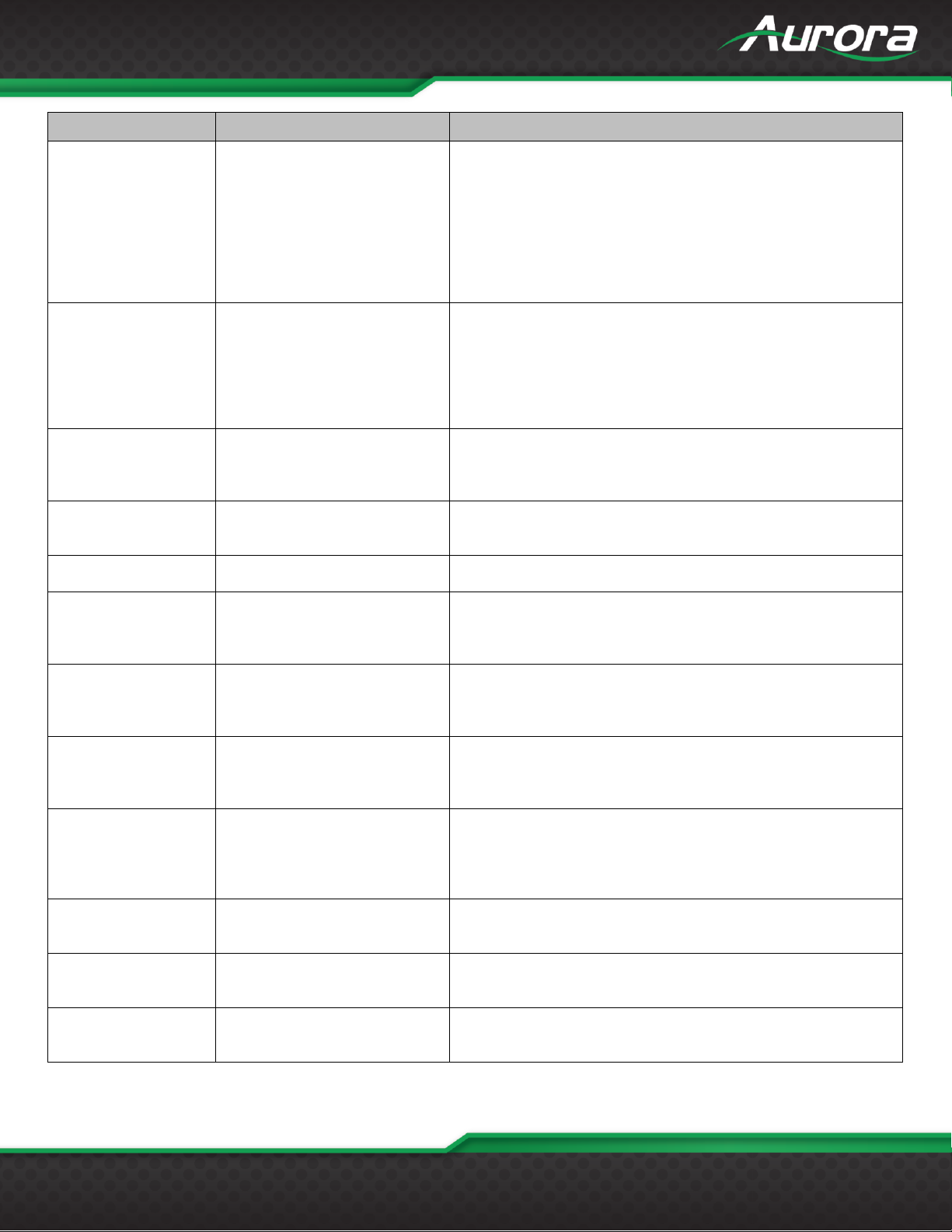
Command
String Format
Information
Button LED Setup
(Individual)
!xBLy,z1,z2,t <cr>
x = Unit address = 0-8 Address Zero is received by all but no
response from units. Response only when set to address 1-8.
Factory default is address 1.
y = Button Number
z1 = Release LED State = R, G, B, N (R = Red, G = Green, B =
Blue, N = None)
z2 = Pushed LED State = R, G, B, N (R = Red, G = Green, B =
Blue, N = None)
t = toggle mode = 0 or 1 (off or on)
Button LED Setup
(All)
!xBA,r1,p1,r2,p2,r3,p3,r4,p4,r5,
p5,r6,p6,r7,p7,r8,p8<cr>
x = Unit address = 0-8 Address Zero is received by all but no
response from units. Response only when set to address 1-8.
Factory default is address 1.
r1- r8 = Release LED State = R, G, B, N (R = Red, G = Green,
B = Blue, N = None, X = Ignore)
p1 - p8 = Pushed LED State = R, G, B, N (R = Red, G = Green,
B = Blue, N = None, X = Ignore)
Send String to
Address 8 in Daisy
Chain Mode
!8PD,z<cr>
z = string is in ASCII and can have non-printable as ASCII
characters as well. To send non-printable ASCII (Hexadecimal)
use a % in front of the 2 ASCII digits. To send “%” then use
%%. Example: Line Feed = 0x0A Hex will be %0A
Set Address
!xADDRy<cr>
x = 0-8. This allows know address to be reassigned or use 0 to
force to new address.
y = Address 1-8
Query Firmware
Revision
?xFM<cr>
x = Address 0-8 Address Zero forces response regardless of
unit address.
Query Button Push
String
?xPSy,b<cr>
x = Unit address = 0-8 Address Zero is received by all but no
response from units. Factory default is address 1.
y = Port Number 1 or 2
b = Button Number 1 - 8
Query Button
Release String
?xRSy,b<cr>
x = Unit address = 0-8 Address Zero forces response
regardless of unit address. Factory default is address 1.
y = Port Number 1 or 2
b = Button Number 1 - 8
Query Hold String
?xHSy,b<cr>
x = Unit address = 0-8 Address Zero forces response
regardless of unit address. Factory default is address 1.
y = Port Number 1 or 2
b = Button Number 1 - 8
Query Toggle String
?xTGy,b,i<cr>
x = Unit address = 0-8 Address Zero forces response
regardless of unit address. Factory default is address 1.
y = Port Number 1 or 2
b = Button Number 1 – 8
I = Instance Number 1 or 2
Query Baud Rate
Setup
?xBRy<cr>
x = Unit address = 0-8 Address Zero forces response
regardless of unit address. Factory default is address 1.
y = port number = 1 or 2.
Query Button LED
Setup (Individual)
?xBLy<cr>
x = Unit address = 0-8 Address Zero forces response
regardless of unit address. Factory default is address 1.
y = Button Number
Query Button LED
Setup (All)
?xBA <cr>
x = Unit address = 0-8 Address Zero is received by all but no
response from units. Response only when set to address 1-8.
Factory default is address 1.
Page 17
USERS GUIDE
www.auroramm.com
16
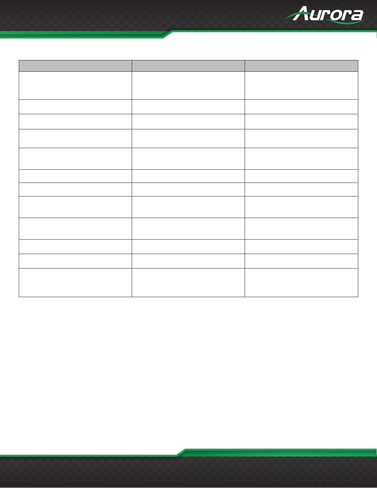
Example
Example String
Example Response
Send Hello_World on button 2 press
on unit address 1 port 1.
!1PS1,2,Hello_World<cr>
~1PS1,2,Hello_World<cr>
Send 0x02 PON 0x03 on button 3
release on unit address 1 port 1.
!1RS1,3,%02PON%03<cr>
~1RS1,3, %02PON%03<cr>
Send Hello%World on button 8 hold
every 100ms on unit address 1 port 1.
!1HS1,8,Hello%%World<cr>
~1HS1,8,Hello%%World<cr>
Set Unit Address 1 Port 1 Baud Rate
to 96008N1.
!1BR1,9600,8N1<cr>
~1BR1,9600,8N1<cr>
Set Unit Address 2 button 1 Release
to green and Push to Red with no
toggle mode
!2BL1,G,R,0 <CR>
~2BL1,G,R,0 <CR>
Force change to address 5
!0ADDR5<cr>
"No response when 0 is used"
Query address 1 firmware.
?1FM<cr>
~1FM-2.0<cr>
Query the push string state. Unit
responds with Hello_World on button 1
press on unit address 4 port 2.
?4PS2,1<cr>
~4PS2,1,Hello_World<cr>
Query the release string state. Unit
responds with Hello_There on button 1
press on unit address 3 port 1.
?3RS1,1<cr>
~3RS1,1,Hello_There<cr>
Send Hello_World on button 1 hold
every 100ms on unit address 1 port 1.
?1HS1,1<cr>
~1HS1,1,Hello_World<cr>
Query Unit Address 1 Port 1 Baud
Rate. Unit responded with 384008N1.
?1BR1<cr>
~1BR1,38400,8N1<cr>
Query Unit Address 2 button 3 LED
state. The response for this example
will be release Blue, Push Red, and
toggle mode on.
?2BL3<CR>
~2BL3,B,R,1<CR>
RS-232 Command Usage
Page 18
USERS GUIDE
www.auroramm.com
17
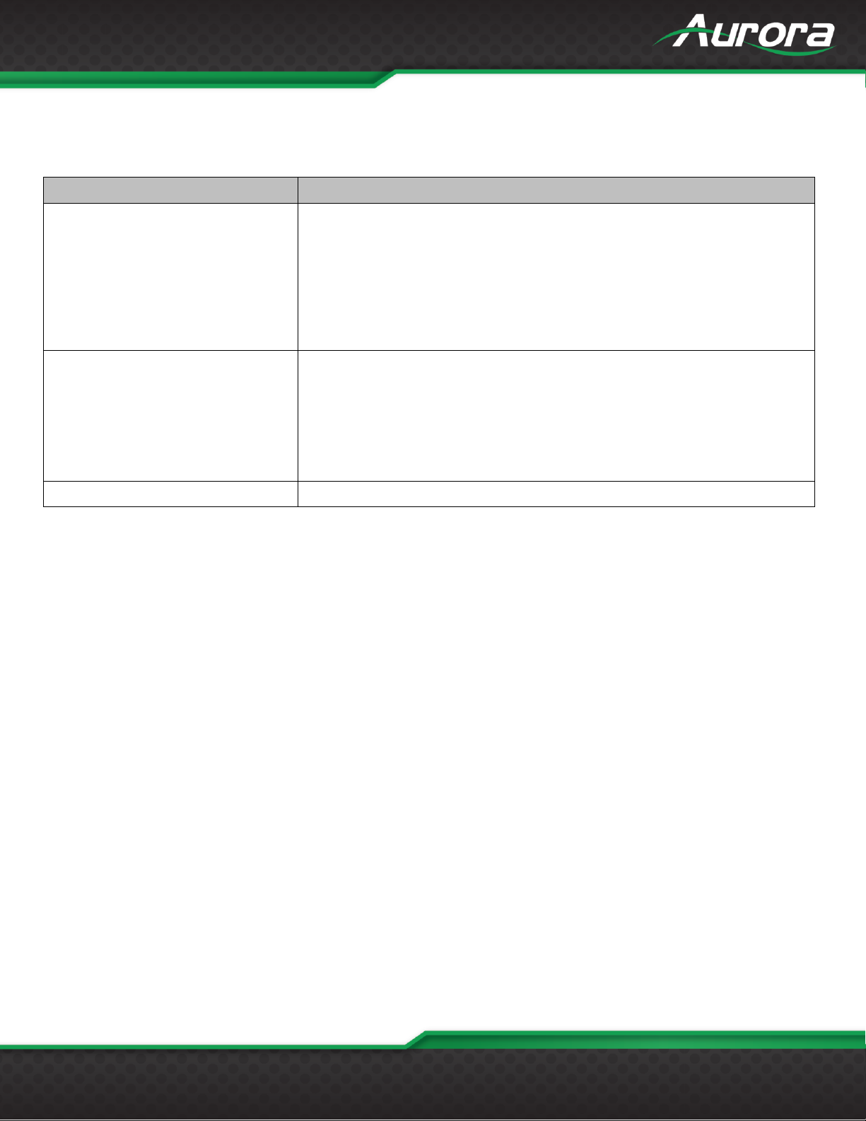
Problem
Solution
1. LED is not lit on any buttons
a. Check 5v power supply is plugged in locally or if connected to DXW-2 make
certain the DXW-2 has power.
b. Check to see if Wall supply is plugged into wall outlet.
c. Make certain wall outlet has power.
d. Make certain RS-232 command for LED state is not set to none for the
buttons.
2. RS-232 does not work
a. Check connection on RS-232 port. Make certain TX goes to RX and RX
goes to TX of the device to be connected. Do not forget about ground.
b. Check baud rate.
c. Verify commands being sent are correct protocol.
d. Each unit must have a unique address.
3. Some functions do not work
a. Make certain unit has latest firmware.
APPENDIX 1
Troubleshooting
Page 19

USERS GUIDE
www.auroramm.com
18
APPENDIX 2
Firmware Update
DXB-8 Update Utility
DXB-8 Update Software requires a serial cable connected in a null (RX to TX, TX to RX, GND to GND) configuration to a
PC. The firmware can be updated directly at either of the DXB-8 rear serial ports. To force update mode holding buttons 1
and 8 for 5 seconds will force unit into firmware update mode for port 1 and holding buttons 4 and 5 for 5 seconds will
force unit into firmware update mode for port 2. LED 1 will light blue when in the mode for port 1 update and LED 2 will
light blue when in mode for port 2 update. A way to force update if necessary is to hold buttons 7 and 8 while applying
power to the DXB-8. Next, use utility to transfer file which can be found at www.auroramm.com.
Page 20
USERS GUIDE
www.auroramm.com
19
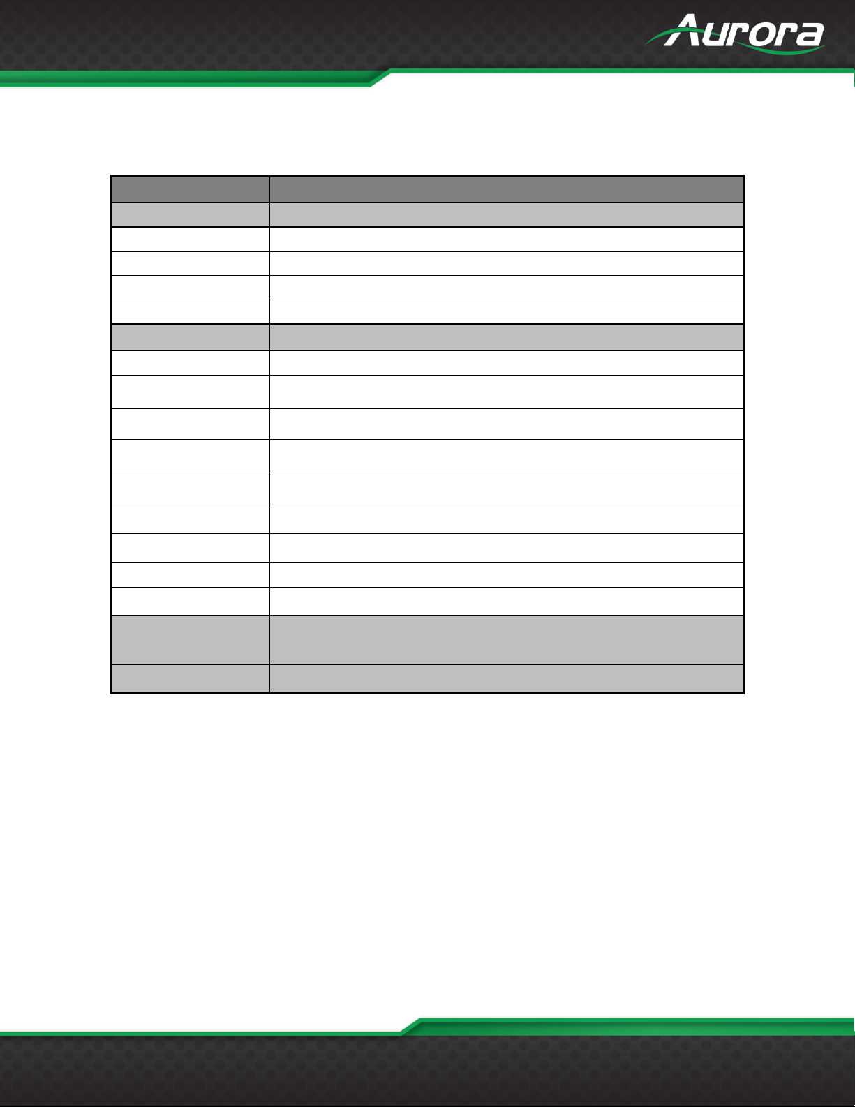
Model Name
DXB-8
Technical
RS-232 Baud Rate
Max 115kbps (Factory default is 9600)
Front Selections
8 Backlit Buttons (Red, Green, Blue)
RS-232 Connector Port 1
4 pin 3.81mm Euro
RS-232 Connector Port 2
3 pin 3.81mm Euro
Mechanical
DXB-8
Housing
Plastic front with aluminum rear enclosure
Dimensions
[L x W x H]
1.44”x4.331”x.76”
*Note: Wall box portion depth .48”.
Weight
.38lbs
Mounting
Wall-mounting Decora® 1 Gang
Power supply
5v 300mA DC
*Note: SN >= SNA1618-0072 allows 5-24vdc operation.
Power consumption
1 Watts [max]
Operation temperature
0~40C [32~104F]
Storage temperature
-20~60C [-4~140F]
Relative humidity
20~90% RH [no condensation]
Package Contents
1x DXB-8
1x Paintable White Wall Plate
1x User Manual
Options
5v DC power Supply for stand-alone operation (PS0045-5)
APPENDIX 3
Technical Specifications
*Note: Specifications subject to change without notice.
Page 21
USERS GUIDE
www.auroramm.com
20
APPENDIX 4
Warranty
Limited 3 Year Warranty
Aurora Multimedia Corporation (“Manufacturer”) warrants that this product is free of defects in both materials and
workmanship for a period of 3 years as defined herein for parts and labor from date of purchase. This Limited Warranty
covers products purchased in the year of 2009 and after. Motorized mechanical parts (Hard Drives, DVD, etc.),
mechanical parts (buttons, doors, etc.), remotes and cables are covered for a period of 1 year. Touch screen displays are
covered for 1 year; touch screen overlay components are covered for 90 days. Supplied batteries are not covered by this
warranty. During the warranty period, and upon proof of purchase, the product will be repaired or replaced (with same or
similar model) at our option without charge for parts or labor for the specified product lifetime warranty period.
This warranty shall not apply if any of the following:
A. The product has been damaged by negligence, accident, lightning, water, act-of-God or mishandling; or,
B. The product has not been operated in accordance with procedures specified in operating instructions: or,
C. The product has been repaired and or altered by other than manufacturer or authorized service center; or,
D. The product's original serial number has been modified or removed; or,
E. External equipment other than supplied by manufacturer, in determination of manufacturer, shall have affected the
performance, safety or reliability of the product; or,
F. Part(s) are no longer available for product.
In the event that the product needs repair or replacement during the specified warranty period, product should be shipped
back to Manufacturer at Purchaser's expense. Repaired or replaced product shall be returned to Purchaser by standard
shipping methods at Manufacturer's discretion. Express shipping will be at the expense of the Purchaser. If Purchaser
resides outside the contiguous US, return shipping shall be at Purchaser's expense.
No other warranty, express or implied other than Manufacturer's shall apply.
Manufacturer does not assume any responsibility for consequential damages, expenses or loss of revenue or property,
inconvenience or interruption in operation experienced by the customer due to a malfunction of the purchased equipment.
No warranty service performed on any product shall extend the applicable warranty period. This warranty does not cover
damage to the equipment during shipping and Manufacturer assumes no responsibility for such damage. This product
warranty extends to the original purchaser only and will be null and void upon any assignment or transfer.
Page 22
www.auroramm.com
21
USERS GUIDE
Aurora Multimedia Corporation
205 Commercial Court | Morganville, NJ 07751
Phone: 732-591-5800 | Fax: 732-591-6801
 Loading...