

Page 1
Revision: 190204
User Manual
USERS GUIDE
DXM G4 Series
DXM-88-G4 ● DMX-1616-G4
Page 2

TABLE OF CONTENTS
TABLE OF CONTENTS 0
PACKAGE CONTENTS 1
INTRODUCTION 1
Description 1
Safety Instructions 1
PRODUCT SERIES DESCRIPTION 2
Matrix Technical Parameters 2
Cards Technical Parameters 4
Card Options 5
Main Control Card 5
HDBaseT card 5
HDMI card 7
DVI card 8
Optic card 9
SDI card 10
CVBS card 11
YPBPR card 12
VGA Card 13
SYSTEM CONNECTION DIAGRAM 14
BASIC OPERATION 14
Capacitive Touch Screen 14
Video Control 16
Switch signal from one input to one or more output ports 16
Switch signal from one input to all outputs 16
Blank Output 16
Audio Control 16
EDID Management 16
System configuration 18
IP Configuration 18
RS232 settings 18
General Settings 19
Show Unit Information 19
WEB SERVER 20
Video Management 20
Video Port Management 21
Changing Name of Port 21
Changing Resolution of Scaler Output Card 21
Activate/Deactivate Cards 21
HDCP Management 22
Switching HDMI/DVI Operating Mode 22
Audio Port Management 22
Serial Management 22
EDID Management 23
Scene Management 23
Scene Setup and Overwiew 23
RS232 AND IP PROTOCOL 25
Page 3

User Guide
1
PACKAGE CONTENTS
● 1 x The Aurora DXM-G4 Series Matrix (DXM-88-G4 or DXM-1616-G4)
● 1 x Power cord
INTRODUCTION
Description
The Aurora DXM-G4 Series Matrix is a modular multi-format matrix for 4K Ultra-HD video
signal and audio management. The device supports flexible video I/O configurations:
• DXM-G4 Series Matrix 8C: Slot 1 to 6 for in- or output cards, Slot 7+8 for output cards
• DXM-G4 Series Matrix 16C: Slot 1 to 12 for in- or output cards, Slot 13 to 16 for output
cards
• DXM-G4 Series Matrix 32C: Slot 1 to 24 for in- or output cards, Slot 25 to 32 for output
cards
DXM-G4 Series Matrix can be configured with optional I/O modules for the following signal
types: HDMI (DVI), HDBT and VGA video format. Optional HDMI scaler output cards allow
seamless switching. The current input/output status is displayed on a front LCD touch display.
Safety Instructions
Please read the instructions carefully and store them
• The switch must be operated at safety low voltage
• Make sure that there is sufficient ventilation for all devices
• The unit may only be stored and used in a dry place
• Please note the safety instructions of the connected equipment
Page 4

User Guide
2
PRODUCT SERIES DESCRIPTION
Matrix Technical Parameters
Type MVP-
8C (N)
MVP-16C MVP-32C
Size 2Urack mounted
3Urack
mounted
5.5Urackmounte
d
Port number 8 16 32
Maximum AV
in/out channel
The 7~8 are
fixation output
channel;
the 1~6 are
input or output
channel
The 13~16 are
fixation output
channel;
the 1~12 are
input or output
channel
The 25~32 are
fixation output
channel;
The 1~24 are
input or output
channel
Center control
number
Not supported 1
Power input AC 100 – 240V 50Hz/60Hz
Power output 24V 4 A 27V 7.5A 28V 11A
Power
dissipation
≤ 96 W ≤ 202.5 W ≤ 308 W
Fuse standard 220 V 1.5A
Redundant
power
●
Storage
temperature/h
umidity
-20℃ ~ 85℃ / 20%~60%
Operating
temperature/h
umidity
0℃ ~ 60℃ / 10%~80%
Altitude limit
0 ~ 2000m
Air pressure
limit
≤ 79.5 kPa
Signal type TMDS
Lever
+0.6 V ~ +1.2 V
Maximum
TMDS
bandwidth
6 G bit/s
Maximum
connector
bandwidth
6 G bit/s
Maximum
audio sampling
48kHz
Maximum color 1080P 36 bit/px; 4K 24 bit/px
Port impedance 50Ω / 100Ω
Clock recovery Auto
DDC protocol DDC DDC2B
DDC lever 5 Volts p-p(TTL)
Switching time
seamless ≤ 1s;common≤ 5s
Serial port
1-bidirectional RS-232,3PIN Phoenix(female)
Page 5

User Guide
3
Type MVP-
8C (N)
MVP-16C MVP-32C
Port define PIN 1:TX PIN 2:GND PIN 3:RX
Baud rate
9600~115200(default),8 data bits,
1 stop bit,none,
Control
protocol
ASCII code
LAN port RJ-45
LAN data rate
10/100BaseT,half/full duplex
Ethernet
support
protocol
ICMP,ARP,IP,TCP,UDP,DHCP,HTTP
Update port RJ45
Update way browser
Cooling system Cool wind
Page 6

User Guide
4
Cards Technical Parameters
Card version Type
Video
signal
type
Resolution
Seaml
ess
switch
ing
EDID/
HDCP
Control
signal/
POE
Audio
embedd
ed
Status
HDTV VESA 4K
MVPS-I-HDMI I HDMI
● ● ●
×
●
×
●
Sale
MVPS-O-HDMI O HDMI
● ● ●
×
●
×
●
Sale
MVPS-I-HDMI2.0 I HDMI
● ● ●
×
●
×
●
Sale
MVPS-O-HDMI2.0 O HDMI
● ● ●
×
●
×
●
Sale
MVPS-I-HDBT1 I HDBT
● ● ●
×
● ● ●
Sale
MVPS-O-HDBT1 O HDBT
● ● ●
×
● ● ●
Sale
MVPS-I-HDBT2 I HDBT
● ● ●
×
● ● ●
Sale
MVPS-0-HDBT2 O HDBT
● ● ●
×
● ● ●
Sale
MVPS-I-VGA- I VGA
● ●
× × × ×
●
Sale
MVPS-I-YPBPR I YPbPr
●
× × × × ×
●
Sale
MVPS-I-CVBS I CVBS
●
× × × × ×
●
Sale
MVPS-I-DVI I DVI
● ●
× ×
●
×
●
Sale
MVPS-I-SDI I 3G SDI
●
× × ×
●
×
●
Sale
MVPS-I-DP I DP
● ● ●
×
○
×
●
MVPS-I-OPTIC I Optic
● ● ●
×
● ○ ●
Sale
MVPS-O-HDMI-S O
HDMI-
S
● ● ● ● ●
×
●
Sale
MVPS-O-DVI-S O DVI-S
● ● ● ● ●
×
●
Sale
MVPS-O-DP-S O DP-S
● ● ● ● ●
×
●
MVPS-0-SDI-S O
3G
SDI-S
●
× ×
●
× ×
●
Sale
MVPS-O-HDBT-S O
HDBas
eT-S
● ● ● ● ● ● ●
Sale
MVPS-O-OPTIC-S O Optic-S
● ● ● ● ● ○ ●
Sale
MVPS-0-VGA-S O VGAS
●
× ×
●
× ×
●
Sale
MVPS-0-YPBPR-S O
YPBPR-
S
●
× ×
●
× ×
●
Sale
note:
● “I”means input card,“O”means output card
● ● : support all character
● ○ : support portion character
● × : Not supported
● HDTV resolution:480i、576i、720p、1080i、1080p
● VESA resolution:800×600 ~ 1920×1200
● 4k resolution:3840×2160
Page 7
User Guide
5
Card Options
Note: Please insert the cards only when power cable is NOT connected to main power supply.
Carefully align and position the cards before tightening the modules with 2 screws. Please
insert or extract cables carefully with power switched off. The last Slot is reserved for the LAN
/ RS232 Communication module ‘CTRL’. Quality cables are highly recommended. Cat cables
are recommend as Cat 6, AWG 23 or better, S/FTP cable.
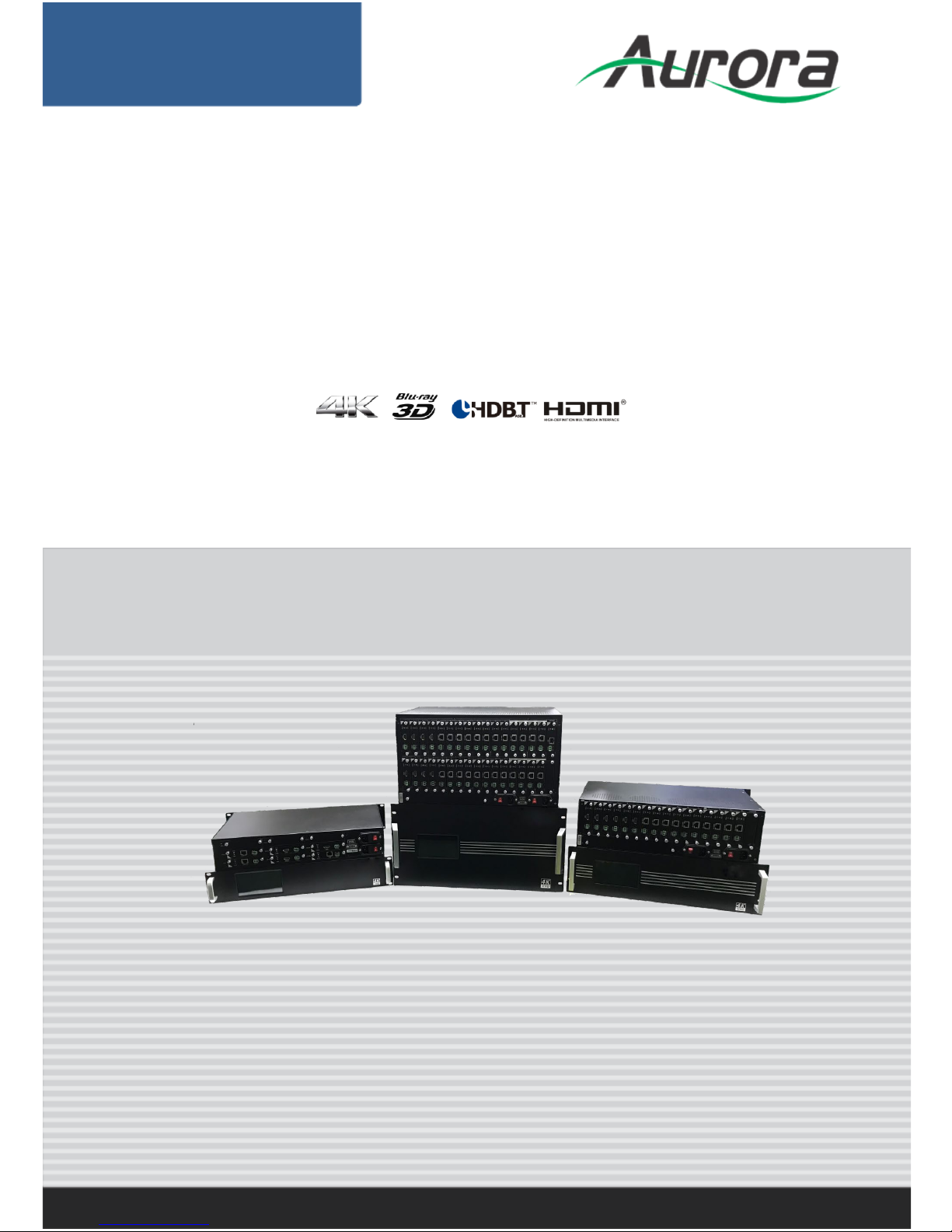
Main Control Card
LEDs:
STA (Status) : Green if signal is active
PWR (Power) : Red if board electricity works accordingly
Technical Parameters
Specification
Type
RS232
1 channel RS232 port
➢
Can be control the matrix by the commands
➢
Support bidirectional
LAN
1 channel LAN port
➢
Can be programmable, support TCP/IP
➢
Support WEB server management
➢ Output control voltage 5V, Upper limit voltage 24V
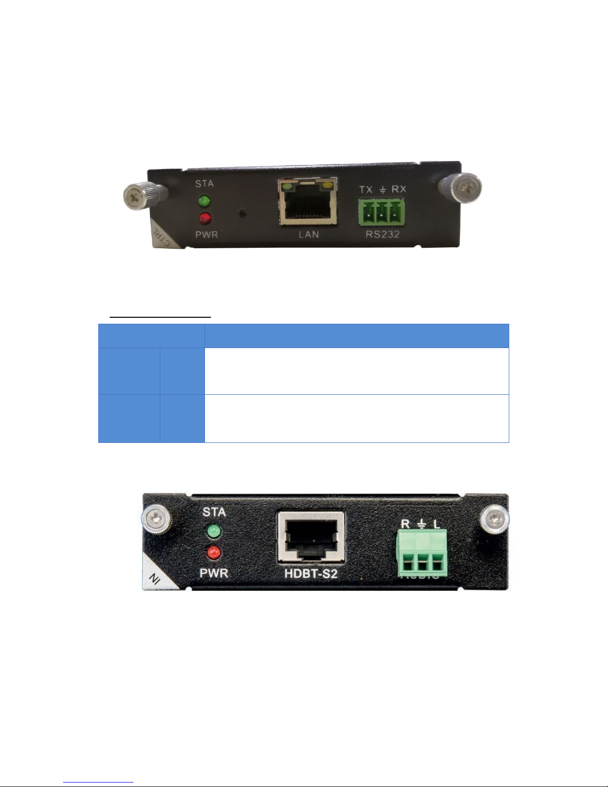
HDBaseT card
Please note, that you must first plug the jumpers at correct position for external power supply
of connected HDBT units, before installation in the matrix.
1 Port HDBT input card with analog audio embedding, supports RS232
passthrough.
LEDs:
STA (Status) : Green if signal is active
PWR (Power) : Red if board electricity works accordingly
Page 8

User Guide
6
Technical Parameters
The board type HDBT1 input HDBT2 input HDBT1 output HDBT2 output
number/Signal
types
A HDBaseT audio and video signals and control signals
The connector
type
RJ-45 8P line terminal
Recommend the
cable type
STP CAT6/CAT6A and above
1080P Maximum
transmission
distance
≤ 70m ≤ 100m
4KMaximum
transmission
distance
≤ 30m(CAT6A) ≤ 60m(CAT6A)
Supporst video
standard
HDTV 1080p @60Hz;VESA 1920×1200;4K 30Hz
Supports color
space
RGB;YCbCr(4:2:2) YCbCr(4:4:4)
Seamless
switching
No support
EDID management
DDC channels, EDID manager
HDCP
management
Settings HDCP authorization or not
Board type
HDBT1 input
HDBT2 input
HDBT1 output
HDBT2 output
Audio embedded embedded De-embedded
Port hot plug support
Power supply Single channel transceiver power supply DC +28V
Storage
temperature/
humidity
-20℃ ~ 85℃ / 5%~40% RH
Work
temperature/humi
dity
0℃ ~ 50℃ / 10%~70% RH
Note Support RS232 pass through, terminal blocks, more flow
The matrix's HDBT modules (PoC) can supply power to connected HDBT modules. Plug in the
jumpers J4 / J5: PoE (right, prepared but not yet available) or PoC (left, see illustration).
Remove the jumpers when connected HDBT modules have their own power supply.
Page 9

User Guide
7
HDMI card
1 Port HDMI input card with analog audio embedding.
LEDs:
STA (Status) : Green if signal is active
PWR (Power) : Red if board electricity works accordingly
Technical Parameters
The board type HDMI input HDMI output
number/Signal
types
A HDMI signal A HDMI signal
The connector
type
HDMI Type A
terminal
HDMI Type A
terminal
Recommend the
cable type
The standard 26AWG HDMI 2.0
Maximum
transmission
distance
≤ 10m
Support video
standard
HDTV 1080p @60Hz;VESA 1920×1200
;
4K@60Hz
Support color
space
RGB;YCbCr(4:2:2) YCbCr(4:4:4)
Seamless
switching
Not supported Support
EDID
management
DDC channels, EDID manager
HDCP
management
Settings HDCP authorization or not
Audio embedded embedded De-embedded
Port hot plug support
Power supply DC +5V 0.25A(1.25W)
Storage
temperature/
humidity
-20℃ ~ 85℃ / 5%~40% RH
operating
temperature/
humidity
0℃ ~ 50℃ / 10%~70% RH
Page 10

User Guide
8
DVI card
1 Port DVI input card with analog audio embedding.
1 Port DVI output card with analog audio de-embedding.
LEDs:
STA (Status) : Green if signal is active
PWR (Power) : Red if board electricity works accordingly
Technical Parameters
The board type MVPS-I1-DVI MVPS-O1-DVI-S
number/Signal types
1 channel DVI-D signal
The connector type DVI-I 24+5
Recommend the
cable type
Standard 26AWG
Maximum
transmission
distance
≤ 10m ≤ 10m
Support video
standard
HDTV 1080p @60Hz;VESA 1920×1200
1080p/720p60Hz
Support color space
RGB;YCbCr(4:2:2) YCbCr(4:4:4)
Seamless switching Not supported Support
EDID management DDC channels, EDID manager Not supported
HDCP management Settings HDCP authorization or not Not supported
Audio embedded embedded De-embedded
Port hot plug Support
Power supply DC +5V 0.25A(1.25W)
Storage
temperature/
humidity
-10℃ ~ 70℃ / 5%~40% RH
operating
temperature/
humidity
0℃ ~ 50℃ / 10%~70% RH
Page 11
User Guide
9
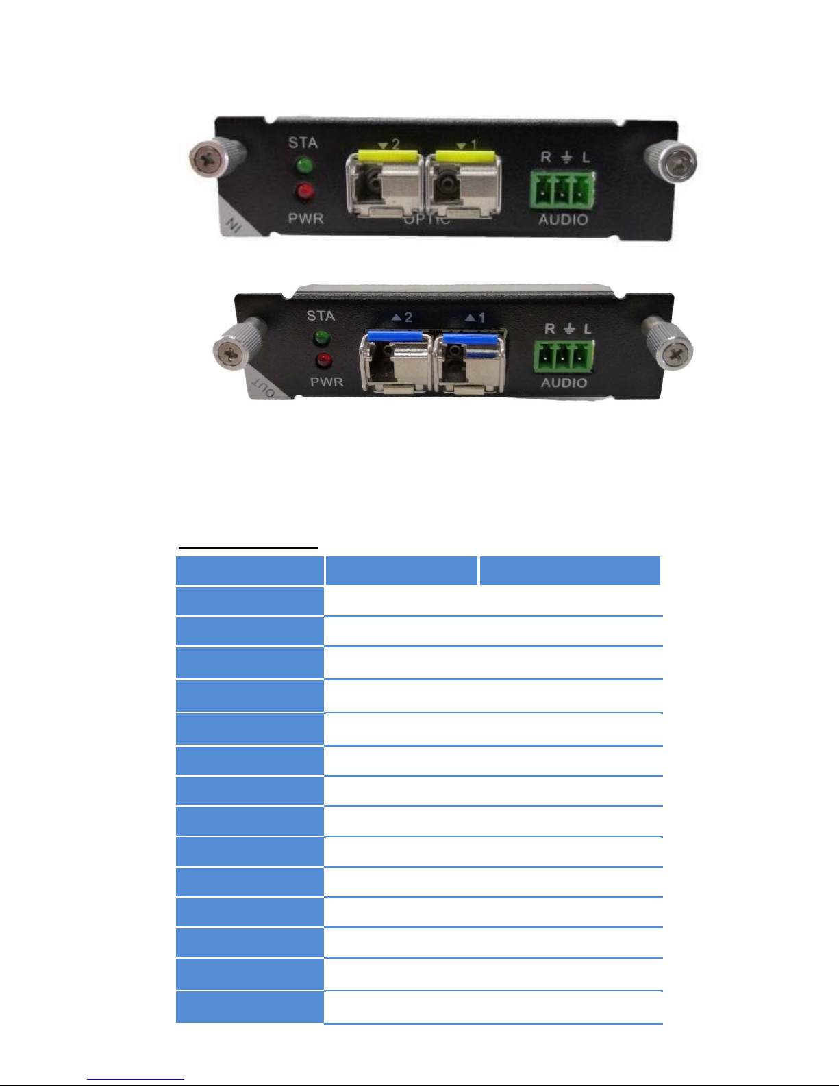
Optic card
1 Port OPTIC input card with analog audio embedding.
1 Port OPTIC output card with analog audio de-embedding.
LEDs:
STA (Status) : Green if signal is active
PWR (Power) : Red if board electricity works accordingly
Technical Parameters
The board type MVPS-I1-Optic MVPS-O1-Optic
number/Signal types 1-core Multi Mode Fiber Video Extender
The connector type LC fiber optic port
Recommend the cable
type
2-core one mode G652.D or Multi Mode OM3
Maximum
transmission distance
single mode≤1500m or multi mode≤300m
Support video
standard
HDTV 1080p @60Hz;VESA 1920×1200
Support color space
RGB;YCbCr(4:2:2) YCbCr(4:4:4)
Seamless switching Not supported Support
EDID management Not supported
HDCP management Not supported
Audio embedded embedded De-embedded
Port hot plug Support
Power supply Not supported
Storage
temperature/humidity
0℃ ~ 60℃ / 5%~40% RH
operating
temperature/humidity
0℃ ~ 45℃ / 10%~70% RH
Page 12

User Guide
10
SDI card
1 Port SDI input card with analog audio embedding.
1 Port SDI-S output card with analog audio de-embedding.
LEDs:
STA (Status) : Green if signal is active
PWR (Power) : Red if board electricity works accordingly
Technical Parameters
The board type MVPS-I1-3GSDI MVPS-O1-3GSDI-S
number/Signal types 1channel SD/HD/3G – SDI siganl
The connector type BNC
Recommend the cable
type
75-5 RG6/RG59
Maximum
transmission distance
RG6 ≤ 120m;RG59 ≤ 80m
Support video
standard
SMPTE-259M/ 274M/292M/296M/ 372M/424M/425M
Support color space
RGB;YCbCr(4:2:2) YCbCr(4:4:4)
Seamless switching Not supported Support
EDID management Not supported
HDCP management Not supported
Audio embedded embedded De-embedded
Port hot plug support
Power supply Not supported
Storage
temperature/humidity
0℃ ~ 60℃ / 5%~40% RH
operating
temperature/humidity
0℃ ~ 50℃ / 10%~70% RH
Page 13

User Guide
11
CVBS card
1 Port CVBS input card with analog audio embedding.
LEDs:
STA (Status) : Green if signal is active
PWR (Power) : Red if board electricity works accordingly
Technical parameters
The board type MVPS-I1-CVBS
number/Signal
types
1 channel CVBS signal
The connector
type
BNC
Recommend the
cable type
Standard 26AWG
Maximum
transmission
distance
≤ 10m
Support video
standard
NTSC/PAL
Support color
space
RGB
Seamless
switching
Not supported
EDID
management
Not supported
HDCP
management
Not supported
Audio
embedded
embedded
Port hot plug Support
Power supply Not supported
Storage
temperature/hu
midity
0℃ ~ 60℃ / 5%~40% RH
operating
temperature/hu
midity
0℃ ~ 50℃ / 10%~70% RH
Page 14

User Guide
12
YPBPR card
1 Port YPBPR input card with analog audio embedding.
1 Port YPBPR output card with analog audio de-embedding.
LEDs:
STA (Status) : Green if signal is active
PWR (Power) : Red if board electricity works accordingly
Technical Parameters
The board type MVPS-I1-YPBPR MVPS-O1-YPBPR-S
number/Signal types
1 channel YPBPR signal
The connector type DB15
Recommend the
cable type
Standard 26AWG
Maximum
transmission distance
≤ 10m
Support video
standard
SJT 11333-2006
Support color space RGB
Seamless switching Not supported Support
EDID management Not supported
HDCP management Not supported
Audio embedded embedded De-embedded
Port hot plug Not supported
Power supply Support
Storage
temperature/
humidity
0℃ ~ 60℃ / 5%~40% RH
operating
temperature/
humidity
0℃ ~ 50℃ / 10%~70% RH
Page 15

User Guide
13
VGA Card
1 Port VGA input card with analog audio embedding.
1 Port VGA-S output card with analog audio de-embedding.
LEDs:
STA (Status) : Green if signal is active
PWR (Power) : Red if board electricity works accordingly
Technical Parameters
The board type MVPI-1-VGA MVPI-1-VGA-S
number/Signal types 1 channel VGA signal
The connector type DB15
Recommend the cable
type
Standard 26AWG
Maximum transmission
distance
≤ 10m
Support video standard
VESA/
HDTV
Support color space RGB
Seamless switching
Not supported
Support
EDID management Not supported
HDCP management Not supported
Audio embedded embedded De-embedded
Port hot plug Support
Power supply Not supported
Storage
temperature/humidity
0℃ ~ 60℃ / 5%~40% RH
operating
temperature/humidity
0℃ ~ 50℃ / 10%~70% RH
Page 16

User Guide
14
SYSTEM CONNECTION DIAGRAM
BASIC OPERATION
Capacitive Touch Screen
The DXM G4 series use a 5” capacitive touch screen, which have a resolution of 800x480, the
layout of system is shown below:
Each particular function button on the interface is shown in the table below.
button function
Page 17

User Guide
15
Video settings
Audio settings
EDID management
System settings
Switches the selected input to all outputs
Close the selected outputs
Save the actual switching state
Restore a switching state
Symbol for output with slot number
Symbol for input with slot number
Audio and video synchronization when switching
Opens main interface
There are four sub-menus in the main menu, which can be selected: Video, Audio, EDID
Management and system settings.
Page 18

User Guide
16
Video Control
The keypad can be used for uninterrupted switching between image input and external
outputs.
Switch signal from one input to one or more output ports
In the video menu select the input by touch. Now press the output/outputs you want switch
to this source to.
At the icon for the output the number of the switched input will appear. This switching is
shown in the display.
Switch signal from one input to all outputs
In the video menu select the input by touch. Now press the button ‘TO ALL’.
This switching is shown in the display.
In the video menu select the input by touch. Now press the output.
This switching is shown in the display.
Blank Output
In the video menu press the button ‘Blank Output’ and the output / outputs you want to
blank. This switching is shown in the display.
Audio Control
Audio can be switched like Video for single or all Outputs to a selected input. They can be
deactivated with ‘Mute Output‘.
EDID Management
Problems with the EDID communication between the signal source and the monitor /
projector often show up when no picture is shown on the display, the picture shows
interference, is out of focus or does not fill the screen.
Usually these most common on-site issues can be solved with a correct EDID management.
With the EDID information, the resolution of the graphics card of the signal generator (e. g.
laptop) is automatically adapted to the resolution of the playback device (e. g. projector).
The EDID information can be read from a terminal connected to the active output (display or
projector).
This EDID can be copied via the touch panel or via the GUI of the Web browser to the
required input. So the individual EDID data is available at the input and request exactly the
same settings from the graphic cards of the signal sources.
Page 19

User Guide
17
At the main menu, select the EDID Management icon. Choose the Output you want to copy
the EDID from and select the input you want to write this EDID to. Now this input will
present that EDID to connected source. On the Screen this Information is shown at the Input
symbol. The EDID tables are storable in the unit via touch screen and Web-Browser.
Page 20

User Guide
18
System configuration
IP Configuration
In the main menu select System settings, ‘NETWORK’ to configure the LAN Settings.
At Server Port you can define the Port for the TCP Connection. Please find the commands at
RS232 protocol.
With activated DHCP the IP Address will be requested from an existing DHCP Server
automatically.
RS232 settings
In the main menu select System settings, ‘UART‘ to configure the RS232 settings.
Page 21

User Guide
19
General Settings
Show Unit Information
Firmware version, Hardware version, MAC adress
Page 22

User Guide
20
WEB SERVER
The factory default settings are:
IP: 192.168.88.229
Port: 80
User: ‘user‘
Password: ‘123456‘
To access the product web server, connect the PC LAN port directly to the Aurora DXM-G4
Series Matrix LAN port with a straight RJ45 cable. After making the connection, go to network
connection of the PC and revise the IP property to static IP as below. Once done, open a web
browser and enter the 192.168.2.245 to access the web server.
To connect the Aurora DXM-G4 Series Matrix to the local area network, please update the
Aurora DXM-G4 Series Matrix product IP to match the LAN network setting from the web
server.
For example if the LAN IP is set as 192.168.88.xxx, then please revise the product to
192.168.88.1xx. Once the IP is set, you access to the device from any PC in the same
network.
Default: User: ‘user‘; password: ‘123456‘
Video Management
The control of the DXM-G4 Series Matrix can be done via a WEB-Browser. The Menu on Top
offers: Video Management, Audio Management, Serial Management, EDID Management, AppScene and System (configuration).
Page 23

User Guide
21
Video Port Management
The Video Management page offers direct, trouble-free switching from any input (source) to
one or more outputs (sinks): for switching, user can select the input (once selected, it will
stay highlighted) and then click on the output tab (or tabs) to switch. Once switched, the
output tab will indicate the input port info once switched.
Changing Name of Port
For switching, you can choose which audio source is used in the top right corner of the pull
down menu. The following options are available:
VE to VE: Source audio to sink +embedded audio to de-embedded
VE to EV: Source audio to de-embedded, embedded audio to sink
E to VE: Embedded audio to sink and de-embedded
E to E: Embedded audio to de-embedded
V to V: Source audio to sink
V to E: Source audio to de-embedded
The name of a slot can only be changed in the Web GUI. In the menu item Video
Management on the right, switch to the view 'S2'. There you can edit the names of the slots
and save them with OK.
Changing Resolution of Scaler Output Card
The output resolution of a scaler card can only be changed in the Web GUI. In the menu item
Video Management on the right, switch to the view 'S2'. There you can set the available
resolutions. Likewise, the brightness, color saturation, contrast and sharpness can be finely
adjusted by +/- 50.
Activate/Deactivate Cards
Page 24

User Guide
22
The power supply of each input/output card can be switched on/off individually for each card
via Web GUI. In the menu item Video Management right-click on the view, S1 '. There you
can switch the supply voltage of the card on and off via pull-down (default: ON).
HDCP Management
The HDCP capability of each input card can be switched individually for each card in the Web
GUI. In the menu item Video Management right-click on the view, S1 '. There you can switch
the HDCP function of the card on and off via pull down (default: ON).
Switching HDMI/DVI Operating Mode
Each HDMI/HDBT output card can be switched from HDMI (default) to DVI. To do this, in the
menu item Video Management, switch right to the view 'S1'. There you can set the format of
each output card to DVI/HDMI by pull down.
Audio Port Management
Choose the Audio Management in the menu bar. Now the available inputs and outputs will be
shown. At first select the source and then the output/outputs.
Note: V means in Video signal embedded, E means external connector. With 'mute output'
the selected output can be muted.
Serial Management
Select serial Management in the menu bar. Now the available RS232 interfaces are displayed
Page 25

User Guide
23
separately according to input and output card. First select the desired source and then the
sink/sink. Now the two RS232 connections are internally routed.
(1)Please switch the Input’s TX to the output’s RX.
(2)Then switch the input’s RX to the output’s TX.
Note: Bidirectional transmission is only possible with a point-to-point connection.
EDID Management
The EDID management via WEB GUI is equivalent to the EDID configuration via touch
screen.
Details can be found in chapter 8.3
Scene Management
The DXM-G4 Series Matrix allows saving and restoring up to 32 scenarios. These can be
saved in the video or audio menu.
The administration of those scenes takes place under the tab 'App-Scene' in the WEB GUI.
Scene Setup and Overwiew
This page combines all important parameters of the DXM-G4 Series Matrix:
• Network and RS232 settings
• Installed firmware versions
• Fan settings
• User administration
• Save and restore the system configuration
• Key tones on/off
• TCP port on/off
Page 26

User Guide
24
Firmware updates can be done with the button ‘System update’ in the right upper corner.
Page 27

User Guide
25
RS232 AND IP PROTOCOL
Your DXM G4 series platform can be controlled by external control devices/system controller
through RS232 connection, TCP/IP over Ethernet. The default RS232 settings are:
● Baud 115200bps
● 8 data bits
● 1 stop bit
● No parity
Action
Basic ASCII
String
Variables
Example
Settings
Example
String
Example
Response
1
Switch the single
channel input of the
video to the single
channel or B12
multiple output
>
Catob,c
<CR>
a = input(1 ~ matrix
max)
b c = output(1 ~ matrix
max or ALL)
Switch the
video input
1 to the
video
output 2
and 3
>
C1to2,3
<CR>
<
C1to2,3
<CR>
2
Switch the video
input channel to the
video output
channel, they’re
correspondence
>
CRa:b,c:d
<CR>
a c = output(1 ~ matrix
max)
b d = input(1 ~ matrix
max)
Switch the
video input
1 to the
video
output 3,
and switch
the video
input 2 to
the video
output 4
>
CR1:3,2:4
<CR>
<
CR1:3,2:4<
CR>
3
Select the video
input channel, it
need to combination
with the >CSWO
command use
>
CSWI:a
<CR>
a = input(1 ~ matrix max)
Select the
video input
2
>
CSWI:2
<CR>
<
CSWI:2
<CR>
4
Select the video
input from The
>CSWI, then switch
to the video out
>
CSWO:a
<CR>
a = output(1 ~ matrix
max)
Select the
video input
from The
>CSWI,
then switch
to the
video
output 2
and 3
>
CSWO:2,3
<CR>
<
CSWO:2,3
<CR>
5
Query the status of
the video output
#
CR
<CR>
NULL
Query
correspondi
ng relations
between
#
CR
<CR>
<
CR1:3,2:4<
CR>
> - Command, # - Query, < - Response
<CR> = 0x0D Hex / 13 Decimal
Note: The default communication settings are 115200 8N1 None. IP
address:192.168.88.229 Socket Server port:1001
Page 28

User Guide
26
Action
Basic ASCII
String
Variables
Example
Settings
Example
String
Example
Response
6
Switch the single
channel input of the
audio to the single
channel or multiple
channel audio out
>
Tatob,c
<CR>
a = input(1 ~ matrix
max) + V/E
b c = output(1 ~ matrix
max or ALL) + V/E
Note:V=Internal audio
E=External audio
the input1's
internal
audio
switch to
the
output2's
internal
and
external
audio
>
T1Vto2V,2E
<CR>
<
T1Vto2V,2E
<CR>
7
Switch the audio
input channel to the
audio output
channel , they’re
correspondence
>
TRa:b,c:d
<CR>
a c = output(1 ~ matrix
max) + V/E
b d = input(1 ~ matrix
max or ALL) + V/E
Note:V=Internal audio
E=External audio
Switch the
audio input
1V to the
audio
output 2V,
and switch
the audio
input 1E to
the audio
output 2E
>
TR1V:2V,1E:
2E
<CR>
<
TR1V:2V,1
E:2E
<CR>
8
Select the audio
input channel, it
need to combination
with the >TSWO
command use
>
TSWI:a
<CR>
a = input(1 ~ matrix max)
+ V/E
Note: V=Internal audio
E=External audio
Select the
audio input
2A
>
TSWI:2V
<CR>
<
TSWI:2
<CR>
9
Select the audio
input from the
>TSWI, then switch
to the audio out
>
TSWO:a
<CR>
a = output(1 ~ matrix
max) + V/E
Note:V=Internal audio
E=External audio
Select the
audio input
from the
>TSWI,
then switch
to the
audio
output 3V
and 3E
>
TSWO:3V,3E
<CR>
<
TSWO:2,3
<CR>
10
Query the status of
audio output
#
TR
<CR>
NULL
Query
correspondi
ng relations
between
#
TR
<CR>
<
TR1V:3V,2
V:4B
<CR>
11
Save the scene
>
Sa
<CR>
a = Scene location(
1~32max)
Save the
current
state to the
10 scene
>
S10
<CR>
<
CR1:3,2:4,.
..
<CR>
12
Call the scene
>
Ra
<CR>
a = Scene location(
1~32max)
Call the
scene 10
>
R10
<CR>
<
CR1:3,2:4,.
..
<CR>
13
Switch the audio and
video synchronization
>
SYNC:a
<CR>
a =
0:no synchronous
1:synchronous
Switch
synchronou
s
>
SYNC:1
<CR>
<
SYNC:1
<CR>
14
Query the status of
the audio and video
synchronization
#
SYNC
<CR>
NULL
Query
synchronou
s
#
SYNC
<CR>
<
SYNC:1
<CR>
Page 29

User Guide
27
Action
Basic ASCII
String
Variables
Example
Settings
Example
String
Example
Response
15
Set the audio and
video synchronization
mode
>
SYNC_MODE:a
<CR>
a = (mode)
0 : VE -> VE
1 : VE -> EV
2 : V -> VE (default)
3 : E -> VE
4 : V -> V
5 : E -> E
6 : V -> E
7 : E -> V
Note: V=Internal audio
E=External audio
Set the
audio and
video
synchroniza
tion mode
>
SYNC_MODE
:1
<CR>
<
SYNC_MOD
E:1
<CR>
16
Query the audio and
video synchronization
mode
#
SYNC_MODE<C
R>
NULL
Query the
audio and
video
synchroniza
tion mode
>
SYNC_MODE
:1
<CR>
<
SYNC_MOD
E:1
<CR>
17
Set the scene name
>
SNAMEa:b
<CR>
a = Scene number
(
1~32max)
b = scene name(15
English char)
Set the
scene10
name to
"Meeting"
>
SNAME10:Me
eting
<CR>
<
SNAME10:
Meeting
<CR>
18
Query the scene
name
#
SNAMEa
<CR>
a = Scene location(
1~32max)
Query the
scene10
name
#SNAME10
<CR>
<
SNAME10:
Meeting
<CR>
19
Whether the scene is
displayed on the
WEB
>
SUSEa:b
<CR>
a = Scene number
(
1~32max)
b = scene use
(0=no display 1=display)
Set the
scene10 for
display on
the WEB
>
SUSE10:1
<CR>
<SUSE10:1
<CR>
20
Query the status of
the scene
#
SUSEa<CR>
a = Scene location(
1~32max)
Query the
scene10
use
#
SUSE10
<CR>
<
SUSE10:1
<CR>
21
Uart switch
>
CUARTatob,c
<CR>
a = RX(1 ~ matrix max)
b c = TX(1 ~ matrix max
or ALL)
Uart switch
rx1 to tx1\2
>
CUART1to1,2
<CR>
<
CUART1to1
,2
<CR>
22
Query the status of
all uart
#CRUART
<CR>
NULL
Query the
status of all
uart
#CRUART
<CR>
<
CRUART1:1
,2:1,...<CR
>
23
Set the IP address
>
IP:a.b.c.d
<CR>
a b c d = address(0~255)
set IP
address to
the
192.168.2.
229
>
IP:192.168.2
.229
<CR>
<
IP:192.168.
2.229
<CR>
24
Set the Subnet
>
SUBNET:a.b.c.d
<CR>
a b c d = address(0~255)
set Subnet
to the
255.255.25
5.0
>
SUBNET:255.
255.255.0
<CR>
<
SUBNET:25
5.255.255.
0
<CR>
25
Set the Gateway
>
GATEWAY:a.b.c
.d
<CR>
a b c d = address(0~255)
set
Gateway to
the
255.255.25
5.0
>
GATEWAY:19
2.168.2.1
<CR>
<
GATEWAY:
192.168.2.
1
<CR>
Page 30

User Guide
28
Action
Basic ASCII
String
Variables
Example
Settings
Example
String
Example
Response
26
Set the Socket Server
port
>
PORT:a
<CR>
a = Server port
Set the
Socket
Server port
to the 1001
>
PORT:1001
<CR>
<
PORT:1001
<CR>
27
Set Network DHCP
>
DHCP:a
<CR>
1= 0:no open 1:open
Set
Network
DHCP for
open status
>
DHCP:1
<CR>
<
DHCP:1
<CR>
28
Query the network
information
#
NETWORK
<CR>
NULL
Query the
network
information
#
NETWORK
<CR>
<
IP:192.168.
2.229
<CR>
<
SUBNET:25
5.255.255.
0
<CR>
<
GATEWAY:
192.168.2.
1
<CR>
<
PORT:1001
<CR>
29
Set the serial port
>
UART:a,b,c,d
<CR>
a = Baud Rate(115200
38400 19200 9600)
b = Data bits(8 9)
c = Stop bits(1 1.5 2)
d = Parity bits(None Odd
Even)
Set the
serial to
the
9600,8,1,N
one
>UART:9600
,8,1,None<C
R>
<
UART:9600
,8,1,None
<CR>
30
Query the serial port
#UART
<CR>
NULL
Query the
serial port
#
UART
<CR>
<
UART:9600
,8,1,None
<CR>
31
Set command
enable, the
commands received
by socket and serial
port will not be
processed after
closing (but the
>CMDEN:a<CR>
command will not be
affected).
>
CMDEN:a
<CR>
a = 0:no make 1:make
Set
command
enable
>
CMDEN:1
<CR>
<
CMDEN:1
<CR>
32
Query the status of
the command enable
#
CMDEN
<CR>
NULL
Query the
status of
the
command
enable
#
CMDEN
<CR>
<
CMDEN:1
<CR>
33
Set the sound when
send the command is
sent
>
CSOUND:a
<CR>
a = 0:no sound 1:sound
Set the
sound
when send
the
command
is sent
>
CSOUND:1
<CR>
<
CSOUND:1
<CR>
Page 31

User Guide
29
Action
Basic ASCII
String
Variables
Example
Settings
Example
String
Example
Response
34
Query the status of
the sound when
command is sent
#
CSOUND
<CR>
NULL
Query the
status of
the sound
when
command
is sent
#
CSOUND
<CR>
<
CSOUND:1
<CR>
35
switch EDID of the
output to the input
port
>
EDIDatob
<CR>
a = output(1 ~ matrix
max)
b = input(1 ~ matrix
max or ALL)
Switch
EDID of the
output 1 to
the input 2
port
>
EDID1to2
<CR>
<
EDID1to2
<CR>
36
switch EDID of the
system to the input
port
>
SYSEatob
<CR>
a = system(1 ~ 16)
b = input(1 ~ matrix
max or ALL)
Switch
system’s
EDID 1 to
the input 2
port
>
SYSE1to2
<CR>
<
SYSE1to2
<CR>
37
Save EDID of the
output to the system
>
SEDIDatob
<CR>
a = output(1 ~ matrix
max)
b = system(1 ~ 16)
Save EDID
of the
output 1 to
system 2
>
SEDID1to2
<CR>
<
SEDID1to2
<CR>
38
Select the output
port to output HDMI
or DVI formats
>
HDMODE:a,b
<CR>
a = output(1 ~ matrix
max)
b = 0:DVI 1:HDMI
Set the
output 2
for HDMI
format
>
HDMODE:2,1
<CR>
<
HDMODE:2
,1
<CR>
39
Open or close the
HDCP of the port
(IN/OUT card)
>
HDCP:a,b
<CR>
a = port(1 ~ matrix
max)
b = 0:OFF 1:ON
Set the
port 2 the
hdcp for off
>
HDCP:2,0
<CR>
<
HDCP:2,0
<CR>
40
Turn on or off the
power of the card
>
CPOWER:a,b
<CR>
a = port(1 ~ matrix
max)
b = 0:OFF 1:ON
Close the
port 2
power
supply
>CPOWER:2,
0<CR>
<
CPOWER:2,
0
<CR>
41
Query the power
status of card
#
CPOWER:a
<CR>
a = port(1 ~ matrix
max)
Query the
power
status of
card 2
#
CPOWER:2<
CR>
<
CPOWER:2,
0
<CR>
42
Set user login WEB
interface’s user name
and password (Arabic
numerals and English
word only)
>
MUNP:a,b
<CR>
a = name(15 the English
characters or Arabic
numerals)
b = password(15 the
English characters or
Arabic numerals)
set user
name:Main
password:1
23456
>
MUNP:Main,1
23456
<CR>
<
MUNP:Main
,123456
<CR>
43
Query management
user name and
password
#
MUNP
<CR>
NULL
Query
manageme
nt user
name and
password
#
MUNP
<CR>
<
MUNP:Main
,123456
<CR>
44
Send commands to
control board
>
COMa
<CR>
a = control card command
send "-
TEST"
string
>
COM-TEST
<CR>
NULL(you
don't online
returns the
ERROR)
Page 32

User Guide
30
Action
Basic ASCII
String
Variables
Example
Settings
Example
String
Example
Response
45
Checking whether
the central control
board is online or not
#
COM
<CR>
NULL
can check
out the
central
control
board is
online by
sending
"#COM<CR
>"to get a
response of
"<COM:1<
CR>"
#
COM
<CR>
<
COM:1
<CR>
46
To TCP Socket server
send data
>
SEND-SS:a:b,c
<CR>
a = IP
b = Server port
c = data
To
192.168.88
.100:1001
send“TEST
”
>
SEND-
SS:192.168.8
8.100:1001,T
EST
<CR>
>
SEND-SS:4
<CR>
47
Query status
information Returned
in JSON format
#
JSON:a,b
<CR>
a =
("video","scene","system",
"weburl","cont")
b = mark(Status update
version,0 = Request all
data)
Query the
state of the
video
>JSON:video
,0<CR>
{
"system":
{
"run":
"Run
000:01:15"
,
"temp":
"20~35",
"ip":
"192.168.8
8.151:8020
",
"wcolor":
"#66ff00",
"mark": 55,
"ahpd": 1,
"uhpd": 1,
"lang": 1,
"update":
true
},
.....
}
48
Set the system
language
>
LANG:a
<CR>
a = 0:English 1:
Chinese
Set the
system
language is
Chinese
>
LANG:1
<CR>
<
LANG:1
<CR>
49
Query system
language
#
LANG
<CR>
NULL
Query
system
language
#LANG<CR> < LANG:1
<CR>
50
Restart the system > SOF-RESTART
<CR>
NULL
Restart the
system
>SOF-
RESTART<C
R>
<
SOF-
RESTART
<CR>
51
Restore the factory
Settings
>
SYS-RESET
<CR>
NULL
Restore the
factory
Settings
>SYS-
RESET<CR>
<
SYS-RESET
<CR>
Page 33

User Guide
31
Action
Basic ASCII
String
Variables
Example
Settings
Example
String
Example
Response
52
Query all the
daughter card types
#
RCID
<CR>
NULL (return data
reference link)
Query all
the
daughter
card types
#RCID<CR>
<
RCID:1:I1,
2:N/A...
<CR>
53
Query main software
version
#
SVER
<CR>
NULL
Query main
software
version
#SVER<CR> < SVER:1.0.0
<CR>
54
Query hardware
version
#
HVER
<CR>
NULL
Query
hardware
version
#HVER<CR> < HVER:1.0.0
<CR>
55
Query the firmware
version of the back
board
#
BVER
<CR>
NULL
Query back
software
version
#BVER<CR> < BVER:1.0.0
<CR>
56
Query the matrix
type
#
M0
<CR>
NULL
Query
matrix type
#
M0
<CR>
<
MVP-16C
<CR>
57
send commands to
HDBT cards
>
SEND-CU:a:xb:c
<CR>
a = baud Rate(115200
38400 19200 9600)
x =I or O
b = card port
c = data
For
example,
send "TEST
" to output
port1
>
SEND-
CU:115200:
O1:TEST
<CR>
Page 34

User Guide
32
Warranty
Limited 3 Year Warranty
Aurora Multimedia Corp. (“Manufacturer”) warrants that this product is free of defects in both materials
and workmanship for a period of 3 years as defined herein for parts and labor from date of purchase.
This Limited Warranty covers products purchased in the year of 2009 and after. Motorized mechanical
parts (Hard Drives, DVD, etc), mechanical parts (buttons, doors, etc), remotes and cables are covered
for a period of 1 year. Touch screen displays are covered for 1 year; touch screen overlay components
are covered for 90 days. Supplied batteries are not covered by this warranty. During the warranty
period, and upon proof of purchase, the product will be repaired or replaced (with same or similar
model) at our option without charge for parts or labor for the specified product lifetime warranty period.
This warranty shall not apply if any of the following:
A. The product has been damaged by negligence, accident, lightning, water, act-of-God or
mishandling; or,
B. The product has not been operated in accordance with procedures specified in operating
instructions: or,
C. The product has been repaired and or altered by other than manufacturer or authorized service
center; or,
D. The product's original serial number has been modified or removed: or,
E. External equipment other than supplied by manufacturer, in determination of manufacturer, shall
have affected the performance, safety or reliability of the product.
F. Part(s) are no longer available for product.
In the event that the product needs repair or replacement during the specified warranty period, product
should be shipped back to Manufacturer at Purchaser's expense. Repaired or replaced product shall be
returned to Purchaser by standard shipping methods at Manufacturer's discretion. Express shipping will
be at the expense of the Purchaser. If Purchaser resides outside the contiguous US, return shipping
shall be at Purchaser's expense.
No other warranty, express or implied other than Manufacturer's shall apply.
Manufacturer does not assume any responsibility for consequential damages, expenses or loss of
revenue or property, inconvenience or interruption in operation experienced by the customer due to a
malfunction of the purchased equipment. No warranty service performed on any product shall extend
the applicable warranty period. This warranty does not cover damage to the equipment during shipping
and Manufacturer assumes no responsibility for such damage.
 Loading...