

Page 1
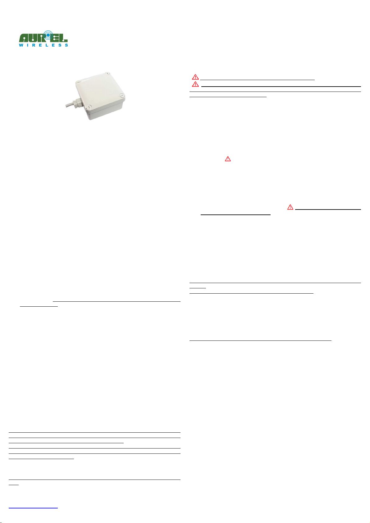
XTR-8LR-REP
-------------------------------------------------------------------------------------------------------------------------------------------------------------------
User manual
DESCRIPTION
XTR-8LR-REP is an half duplex repeater based on LoRa
long range communication, high interference immunity , very high sensitivity and low
current consumption.
The repeater XTR-8LR-REP allows to enlarge the RF radio coverage between the Aurel
XTR-8LR-4ZN or XTR-8LR-SOS keyfob (or XTR-8LR-ENC encoder) and the paired XTR8LR-DEC decoder.
85 - 264VAC power supply, IP55 enclosure and integrated antenna.
The device embeds a supercapacitor for temporary power supply backup in case the
primary power fails.
OPERATION
The XTR-8LR-REP repeats the packets received from Aurel XTR-8LR-4ZN and XTR-8LRSOS keyfobs or Aurel XTR-8LR-ENC encoders.
In TRANSPARENT MODE (see "INSTALL THE XTR-8LR-REP" section below) it repeats
packets received from all Aurel keyfobs (or encoders), in LEARN MODE it repeats only
the packets received from learned keyfobs or encoders (see "LEARN PROCEDURE"
section below).
XTR-8LR-REP repeats the received packets with the following timing:
1. XTR-8LR-4ZN keyfob or encoder in "Without retry mode": 500msec after the last
received packet. This means that, if the user maintains the button pressed on the
keyfob, the XTR-8LR-REP doesn't repeat any packet. When the user releases the
button the keyfob stops transmitting and, after 500msec, the XTR-8LR-REP repeats
the last received packet. For this reason it is suggested to have brief button
pressures on the keyfob.
2. XTR-8LR-SOS keyfob or Encoder in "With retry mode" : immediately after a
received packet. Note: the system works properly only with XTR-8LR-ENC firmware
version 1.9 or later.
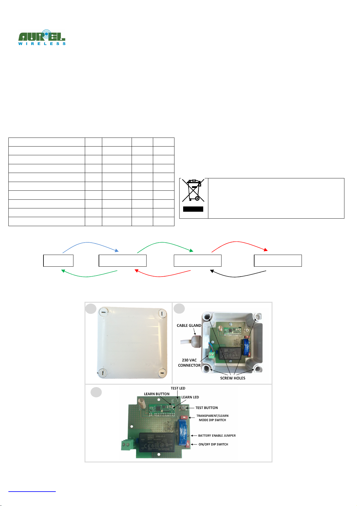
To reach the decoder a keyfob can use more than one XTR-8LR-REP as relay (see Figure
1) obtaining a multi-hop communication.
Figure 1 shows a schematic flow of packets in an example of installation with two hops
(XTR-8LR-REP) between the keyfob and the decoder:
• the keyfob transmits a stream of packets during the button pressure. When the
user releases the button the keyfob transmits the last packet (Packet#1) and it
stops transmitting;
• the XTR-8LR-REP #1 repeats Packet #1 : it transmits the Packet #2 identical to
the Packet #1. This packet is received by the keyfob and by the XTR-8LR-REP #2;
• the XTR-8LR-REP #2 receives the Packet #2 and repeats it : it transmits the
Packet #3 identical to the Packet #1. This packet is received by the XTR-8LR-DEC
and by the XTR-8LR-REP #1;
• the keyfob uses the Packet #2 as acknowledge packet;
• the XTR-8LR-DEC receives the Packet #3, activates the output and transmits the
acknowledge packet (Packet #4) that is received by the XTR-8LR-REP #2;
• XTR-8LR-REP #1 doesn't repeat the Packet #3 (and in a similar way the XTR-8LRREP #2 doesn't repeat the Packet #4) because that packets are identical to an
already received packet by the repeater (respectively Packet #1 and Packet #2).
As you can see from the Figure 1 and related description, the keyfob only knows that the
Packet#1 is received by the closer XTR-8LR-REP and it doesn't know if the command is
really received (after one or more hop) by the XTR-8LR-DEC.
For this reason the keyfob never knows the status of the output on the decoder
therefore it always shows the reception of the ack packet with the GREEN LED ON for
600msec even if the decoder output is set in bistable mode.
In a similar way the encoder always shows the reception of the ack packet with the ACK
RECEIVED pin ON for 100msec (even if the decoder output is set in bistable mode and
the output has been deactivated).
During the installation it is possible verify the RF link between the XTR-8LR-REP and
another XTR-8LR-REP o the XTR-8LR-DEC (see "RADIO LINK TEST" section).
Note: the RF link test works properly only with XTR-8LR-DEC firmware version 1.9 or
later.
The technical features can change without forecasting. AUR°EL S.p.A doesn’t assume any responsibility of damage due to the improper use of the device.
------------------------------------------------------------------------------------------------------------------------------------------------------------------------------------------------------------------------------
Aurel S.p.A via Foro dei Tigli 4, 47015 Modigliana (FC) ITALY 06/06/2019 - Rev. 2.0
Tel:(+39)0546941124, Fax:(+39)0546941660, http: www.aurelwireless.com
TM
modulation providing an ultra
INSTALL THE XTR-8LR-REP
This symbol indicates a possibly dangerous situation
CAUTION: risk of injury by electric shock. A licensed electrician with
knowledge and understanding electrician systems and electrical safety should
complete the electrical installation.
1. Turn the screws on the housing into position 0 (see Figure 2.1) and remove the
cover.
2. Secure the housing on the wall using four screws (Ø4 mm max.), see figure 2.2.
Make sure the screws are suitable for use with the given type of wall.
3. Shut off the main circuit breaker of the building for safety during the installation
and ensure the wires are not short circuited during the installation.
4. Use a multicore cable with 2 cores of section from 1.5mmq to 2.5mmq. The
maximum external dimension of the cable must be in the range 6 - 12mm.
5. Insert the multicore cable in the gland (see figure 2.2).
6. Insert each core of the cable on the 230VAC connector and tighten the screw (see
figure 2.2). ATTENTION: when carrying out installation work, always
ensure that the connecting cable is not damaged or crushed.
7. Select the mode of operation through the TRANSPARENT/LEARN MODE DIP
SWITCH (see figure 2.3): if the dip switch is in LEARN MODE position the XTR-8LRREP works in LEARN MODE, if the dip switch is in TRANSP. MODE position the
device works in TRANSPARENT MODE.
8. Move the ON/OFF DIP SWITCH to the ON position.
9. Remove the BATTERY ENABLE JUMPER (see figure 2.3) if you do not need the
temporary supply backup in case the primary power fails.
10. Restore power at the main circuit breaker. DANGER : touching live parts
can result in an electrical shock.
11. If the device works in LEARN MODE, save the keyfobs on the XTR-8LR-REP
through the LEARN PROCEDURE (see section below).
12. Perform the Radio Link Test (see section below) to verify the RF link between the
XTR-8LR-REP and another XTR-8LR-REP or XTR-8LR-DEC.
13. Replace the cover and turn the screws into position 1 (see Figure 2.1).
LEARN PROCEDURE
1. Press and release the LEARN BUTTON (see figure 2.3).
2. The LEARN LED (see figure 2.3) blinks quickly for 10 seconds.
3. Within this time press a push button on the keyfob : the LEARN LED stays on for 1
second to confirm the learning of the keyfob.
4. Repeat the procedure from point 1 to 3 for all keyfobs you need to learn.
Note: on the XTR-8LR-REP it is necessary to learn all the keyfobs learned on the
decoder.
Note : the learn procedure works only if the LEARN MODE is set.
MEMORY ERASE PROCEDURE
1. Press and release the LEARN BUTTON.
2. The LEARN LED blinks quickly for 10 seconds.
3. Within this time press the LEARN BUTTON again and maintain it pressed. The
LEARN LED turns ON and, after 5 seconds, it turns OFF. At this time release the
LEARN BUTTON.
4. The LEARN LED blinks 5 times to confirm the memory erase.
Note : the memory erase procedure works only if the LEARN MODE is set.
RADIO LINK TEST
Before performing the radio link test it is necessary to register on the XTR-8LR-REP a
keyfob already learned on the decoder XTR-8LR-DEC:
1. Press and maintain pressed the TEST BUTTON (see figure 2.3).
2. After 5 seconds the TEST LED (see figure 2.3) starts blinking then release the
TEST BUTTON.
3. During the TEST LED blinking (10 seconds) press a push button on a keyfob
already learned on the decoder: the TEST LED stays on for 1 second to confirm the
registration of the keyfob.
At this point it is possible to perform the link test between the XTR-8LR-REP and another
XTR-8LR-REP or the decoder:
1. Press quickly the TEST BUTTON.
2. When the TEST BUTTON is released the TEST LED starts blinking.
3. If the RF link is OK the TEST LED stops blinking and stays ON for about 2 seconds.
If the RF link is NOT OK the TEST LED continues to blink for about 3 seconds.
If in the installation there are more than one hop (XTR-8LR-REP) between the keyfob
and the decoder it is suggested to start the installation from the XTR-8LR-REP closer to
the decoder and proceed with the other XTR-8LR-REP.
With reference to Figure 1 proceed as follows:
1. Install the XTR-8LR-REP #2 closer to the decoder.
2. Perform the RF link test between the XTR-8LR-REP #2 and the decoder.
3. Install the XTR-8LR-REP #1 and perform the RF link test between the XTR-8LRREP # 1 and the XTR-8LR-REP #2.
Page 2
KEYFOB
XTR-8LR-REP
XTR-8LR-REP
XTR-8LR-DEC
Packet #1
Packet #2
Packet #3
1 2
3
XTR-8LR-REP
-------------------------------------------------------------------------------------------------------------------------------------------------------------------
User manual
4. Test the link between the XTR-8LR-REP #1 and the keyfob pressing the button on
the keyfob and verifying the reception of the ACK packet (green led ON for 600
msec).
TURN OFF THE XTR-8LR-REP
If it is necessary to turn off the device (e.g. for maintenance purposes) proceed as
follow:
1. Shut off the main circuit breaker of the building.
2. Turn the screws on the housing into position 0 (see Figure 2.1) and remove the
cover.
3. If the BATTERY ENABLE JUMPER is closed, move the ON/OFF DIP SWITCH to the
OFF position.
Technical characteristic
Characteristics Min. Typ. Max. Unit
Power supply 85 264 VAC
Average power consumption < 1 W
RF carrier frequency 868.3 MHz
European ISM Band 868 - 868.6 MHz
Modulation LoRa™
ERP RF Power 13 dBm
Sensitivity -126 dBm
Operating time without power supply 24 h
Box IP rating IP 55
Packet #2
Packet #3
Manufacturer's Declaration of Conformity EU
Hereby, Aurel S.p.A. declares that the radio equipment type XTR-8LR-REP is in
compliance with Directive 2014/53/EU. The full text of the EU declaration of conformity
is available at the following internet address:
http://www.aurelwireless.com/declaration-of-conformity/
The device operates at 868.3MHz (ISM frequency band 868.00 - 868.60 MHz) with
maximum radiated power of 13dBm.
The device is a “Class 1” radio equipment as defined in article 1(1) of European
Commission Decision No. 2000/299/EC of 06/04/2000. Class 1 radio equipments can be
placed on the market and be put into service without restrictions on all EU member
states.
Recommendation CEPT 70-03
The device operates in a harmonized frequency band and therefore, in order to comply
with current regulations, the device must be used on the time scale with a maximum
duty-cycle time of 1% (equivalent to 36 seconds usage on 60).
WEEE Marking
Once the product life-span has expired, the product must be
disposed of in a different way from other wastes. The user must to
put the equipment at the collection points for electronic and electrical
waste. Illegal disposing of this product, is punishable by law and will
be dealt with according to the laws of the individual member nation
of EU.
Packet #4
Figure 1
Figure 2
The technical features can change without forecasting. AUR°EL S.p.A doesn’t assume any responsibility of damage due to the improper use of the device.
------------------------------------------------------------------------------------------------------------------------------------------------------------------------------------------------------------------------------
Aurel S.p.A via Foro dei Tigli 4, 47015 Modigliana (FC) ITALY 06/06/2019 - Rev. 2.0
Tel:(+39)0546941124, Fax:(+39)0546941660, http: www.aurelwireless.com
 Loading...