

Page 1
---------------------------------------------------------------------------------------------------------------------------------------------------
PRELIMINARY
XTR-7020A-4
Owner’s Manual
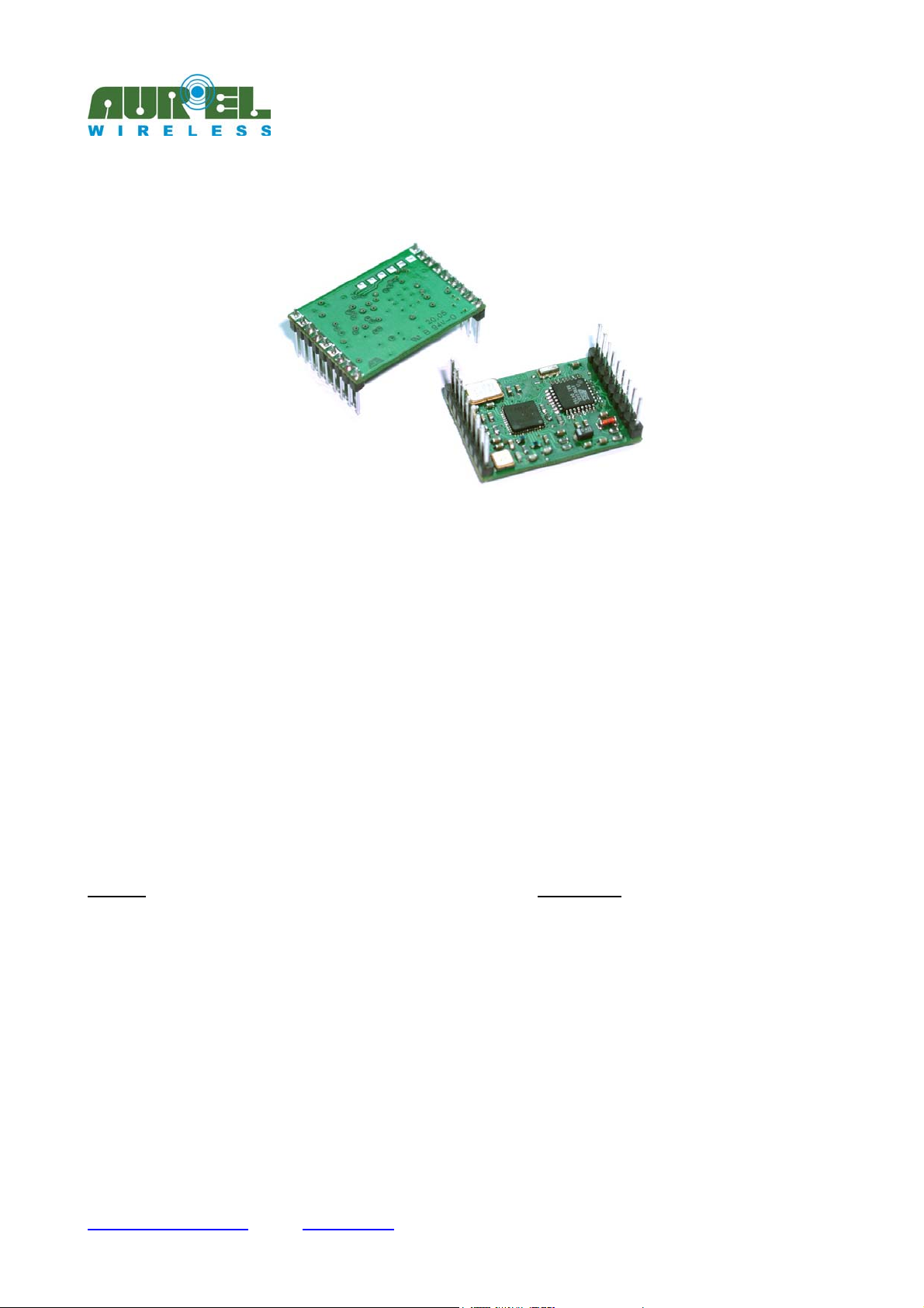
The XTR-7020A-4 is a 10 channel transceiver which compared with the XTR-903A-4, offers improved performance,
as such as longer RF range, serial transmission speed and error checking. It has the same pin out.
The data is transmitted in FSK modulation which assures a larger immunity to noise compared with amplitude
modulation, allowing a range of more than 300 m in free air, by using omnidirectional antennas.
The XTR-7020A-4 allows data transfer by TTL RS-232 logic by utilising a microcontroller which operates the
redundance over the RF data.???? The speed of the data at the input serial port (9600-19200-38400 bps and 960057600-115200 bps according to S5 register setting) can be set through SP1 and SP2 pins.
The data transmission is carried out according to store and forward technique: the data entered the serial port is
memorized in a buffer and forwarded only at the end of their reception. During RF reception phase the bytes are
memorized and transferred to the serial port only after checksum validation. In case of failure the whole lot is rejected.
The data transmission delay (between input and output ports), depends upon packet length and speed of both serial
connections.
The high serial speeds (57600-115200bps) available, allows compensation of the introduced packaging delays: for
instance a 64 Byte case, at a serial speed of 115200bps, the transmission delay shall be around 21ms, which is
comparable, therefore, to XTR-903A-4.
The maximum packet length is 240 Byte.
By sending ‘AT’ type commands the communication channel, the serial speed and the outlet power can be selected and
the RF channel occupation be monitored.
The module is mechanicaly compact and maintains the same reduced dimensions of the XTR-903A-4 model (23 x 33
mm). The supply voltage is 3 Volt.
The maximum power consumption is reduced to 10 µA. in stand-by condition
Features
RS-232 signals store and forward operation
No code or preamble demanded to User
AT Commands for internal registers programming
HyperTerminal* compatible
Number of channels: 10
Compact dimensions (23x33 mm)
Bit rate: 9600, 19200, 38400, 57600, 115200 bps
Power transmitted: 10 mW max.
3v power supply
Typical range: 300 m
Applications
Wireless handsfree
House automation
Telemetry
Access control ???
Instruments monitoring
Data acquisition
POS terminals
* Trade Mark by Hilgraeve, Inc.
Technical specifications may be changed without notice. AUR°EL S.p.A. declines all responsabilities deriving from a wrong utilisation of the equipment.
---------------------------------------------------------------------------------------------------------------------------------------------------------------------
Tel.: +39.0546.941124 Fax: +39.0546.941660
http://www.aurelwireless.com - email: [email protected]
Dec. 20 th 2005AUR°EL S.p.A. Via Foro dei Tigli, 4 - 47015 Modigliana (FC) – ITALY
Pag 1 of 1
Page 2
---------------------------------------------------------------------------------------------------------------------------------------------------
PRELIMINARY
XTR-7020A-4
Owner’s Manual
Absolute limits
Operating temperature -20 °C ÷ +70 °C
Storage temperature -40 °C ÷ +100 °C
Power supply +6V
Input voltage -1.0 ÷ Vcc + 0.3V
Output voltage -1.0 ÷ Vcc + 0.3V
Technical features
Min. Typ. Max. Unit
DC Levels
Supply voltage 2.7 3.3 3.6 V
Power consumption (rx mode) 26 mA
Power consumption (tx mode @ -8 dBm) 20 mA
Power consumption (tx mode @ 10 dBm) 31 mA
Power consumption (stand-by mode)
Logic level “1” in input/output 0.7xVcc Vcc V
Logic level “0” in input/output 0 0.3xVcc V
RF
Band 433.19÷434.57 MHz
Modulation type FSK
RX Sensibility (@115200 bps) -100 dBm
TX Power -8 10 dBm
Performance
Serial Bit Rate
Outdoor range 300 m
Number of channels 10
Channel Spacing 153.6 kHz
Commutation times
PWRDN → RX
TX → RX
RX → TX
Default setting
Channel 433.96 MHz
Output Power (tx) 10 dBm
1
As input serial signal is intended 8,n,1.
Technical specifications may be changed without notice. AUR°EL S.p.A. declines all responsabilities deriving from a wrong utilisation of the equipment.
---------------------------------------------------------------------------------------------------------------------------------------------------------------------
Tel.: +39.0546.941124 Fax: +39.0546.941660
http://www.aurelwireless.com - email: [email protected]
1
8 10
9600, 19200, 38400, 57600, 115200 bps
TBD ms
TBD
TBD
µA
ms
ms
Dec. 20 th 2005AUR°EL S.p.A. Via Foro dei Tigli, 4 - 47015 Modigliana (FC) – ITALY
Pag 2 of 2
Page 3
---------------------------------------------------------------------------------------------------------------------------------------------------
PRELIMINARY
XTR-7020A-4
Owner’s Manual
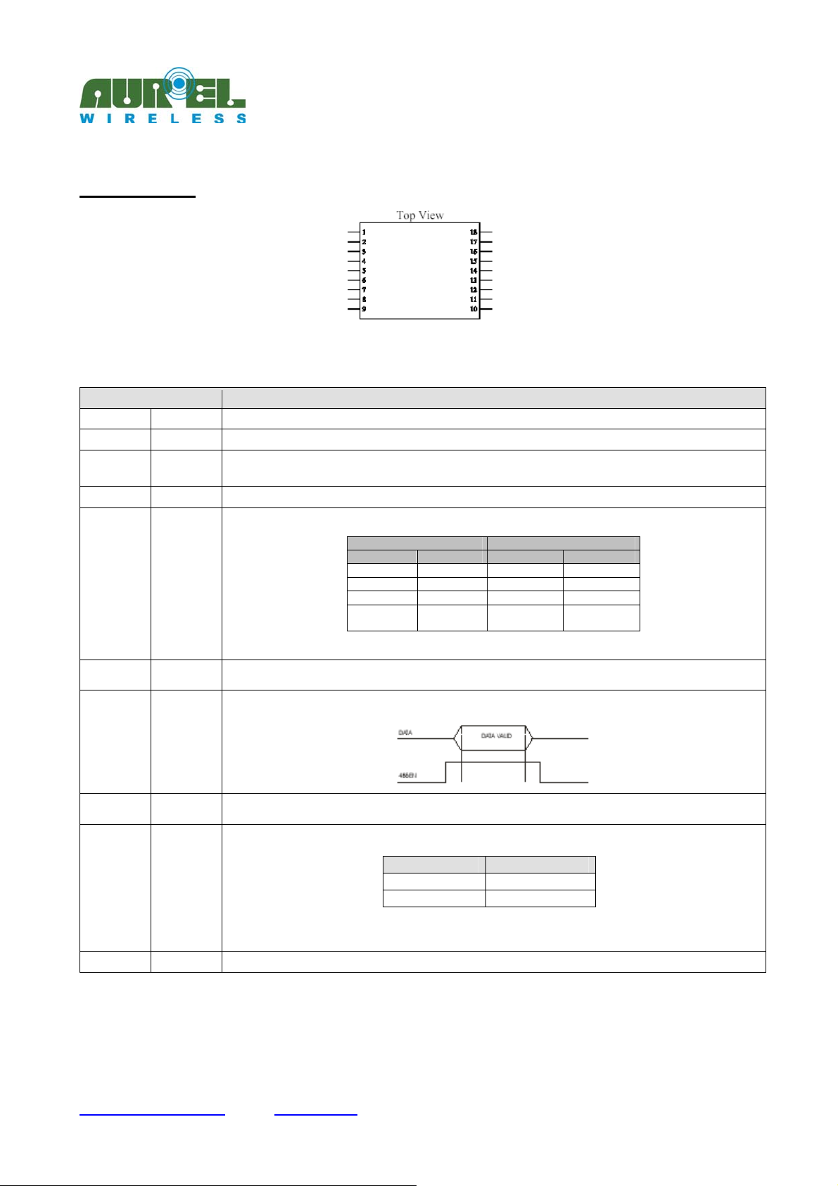
Pins description
Pin Description
1,3
2
4, 5, 6, 7,
8
9,10,18
11,15
12
13
RF GND
ANT
/
GND
SP1, SP2
RSRX
485EN
XTR-7020A-4
Fig. 1: Device’s pinout
Connection with RF ground plane
Antenna connection, 50 ohm impedance
Not in use in this model
Connection to ground plane
Serial speed selection pins. The selection must be carried out before switching on the device
Serial data output with TTL RS-232 logic with 1 start bit (0V), 8 data bit and 1 stop bit (3V). The line must be driven
at high logic level (3V)
The 485EN line allows to drive the RS-232 / RS-485 interface. In correspondence of the output data on the RSRX
line, the signal reches a high logic level.
Jumper Serial speed
S1 S2 S5=0 S5=1
Open Close
Close Open
Open Open
Close Close
38400 115200
19200 57600
9600 9600
Test Mode:
pseudonoise
Test Mode :
data packet
14
16
RSTX
PWRDN
Serial data input with TTL RS-232 logic with 1 start bit (0V), 8 data bit and 1 stop bit (3V). The line must be driven
at high logic level.
Device state. In Power Down the transceiver XTR-7020A-4 goes off reducing the consumption to less than 10µA.
PWRDN STATE
0 On
1 Off
It is recommended not to leave the pin under a variable voltage if inactive, in order to prevent module’s
malfunctionings
17
Vcc
Module’s supply (3V), duly filtered and adjusted.
Tab. 1: Pins description
Technical specifications may be changed without notice. AUR°EL S.p.A. declines all responsabilities deriving from a wrong utilisation of the equipment.
---------------------------------------------------------------------------------------------------------------------------------------------------------------------
Tel.: +39.0546.941124 Fax: +39.0546.941660
http://www.aurelwireless.com - email: [email protected]
Dec. 20 th 2005AUR°EL S.p.A. Via Foro dei Tigli, 4 - 47015 Modigliana (FC) – ITALY
Pag 3 of 3
Page 4
---------------------------------------------------------------------------------------------------------------------------------------------------
PRELIMINARY
XTR-7020A-4
Owner’s Manual
XTR-7020A-4 Operating mode
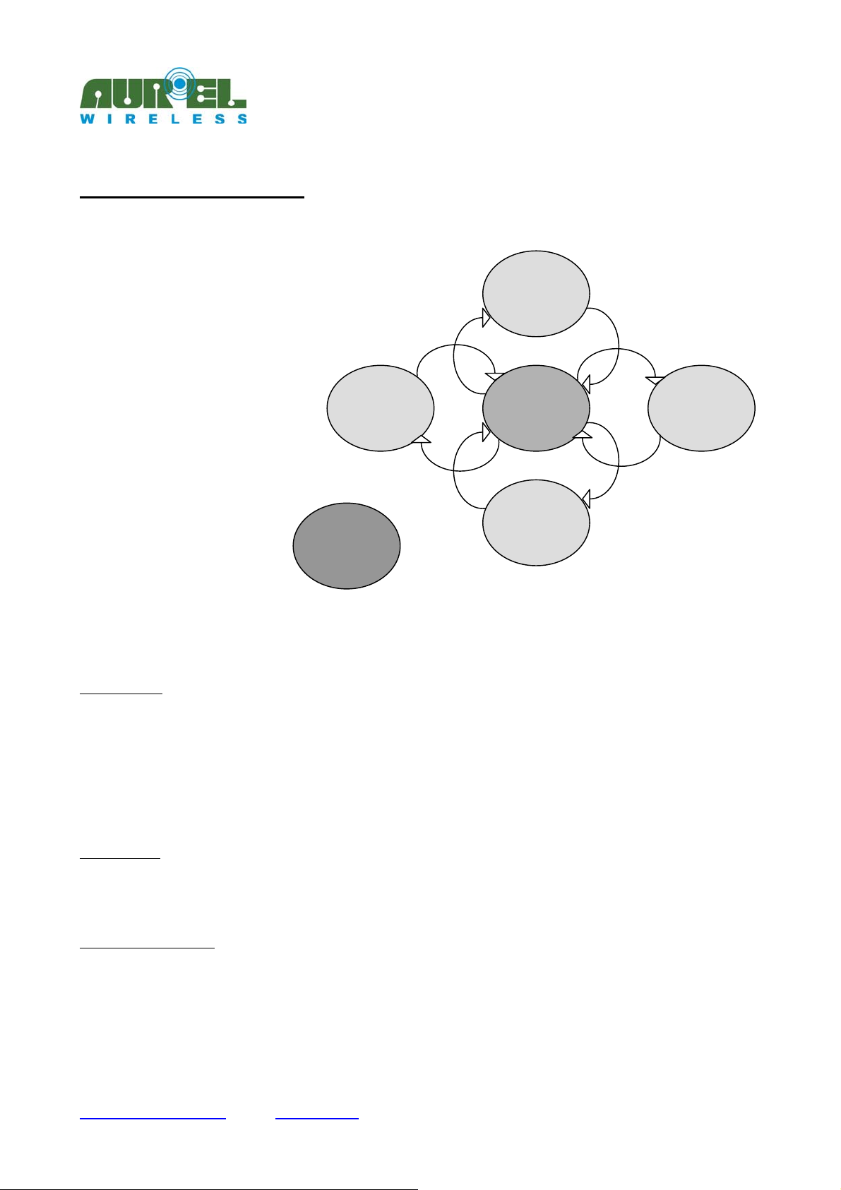
The device’s operating modes can be summarized in 6 conditions (Fig. 2):
1. Test Mode
2. Idle Mode
3. RF Transmit Mode
4. RF Receive Mode
5. Power Down Mode
6. Command Mode
1. Test Mode
The Test Mode can be reached by short circuiting pins SP1 and SP2 to ground, prior to switching on the
device. According to S5 register containt, two different test modes can be obtained:
• S5=0: An RF continuous transmission of a carrier madulated by a 20 kHz signal composed by a
sequence of pseudorandom data.
• S5=1: Transmission of a data packet defined by a 4 digits incremental numerical value.
To exit such mode the supply must be cut off and a new configuration of SP1 and SP2 must be selected.
Test Mode
Power
Down
Mode
RF
Transmit
Mode
Idle
Mode
Command
Mode
Fig. 2 Operating modes
RF
Receive
Mode
2. Idle Mode
It is the initial rest state of the device when is switched on (if SP1 and SP2 select the Test Mode): in such
operating mode the transceiver waits the data reception from RF or from the RSTX serial line.
3. RF Transmit Mode
From the inactive condition (Idle Mode) the module switches to an RF transmission state, when on the
RSTX input line (pin 14) is available a start bit (low logic level, 0V) and consequently at list one byte of
data.
The mechanism of data transfer Store & Forward may be described by pairs of operations in a sequence.
Technical specifications may be changed without notice. AUR°EL S.p.A. declines all responsabilities deriving from a wrong utilisation of the equipment.
---------------------------------------------------------------------------------------------------------------------------------------------------------------------
Tel.: +39.0546.941124 Fax: +39.0546.941660
http://www.aurelwireless.com - email: [email protected]
Dec. 20 th 2005AUR°EL S.p.A. Via Foro dei Tigli, 4 - 47015 Modigliana (FC) – ITALY
Pag 4 of 4
Page 5
g
R
---------------------------------------------------------------------------------------------------------------------------------------------------
PRELIMINARY
XTR-7020A-4
Owner’s Manual
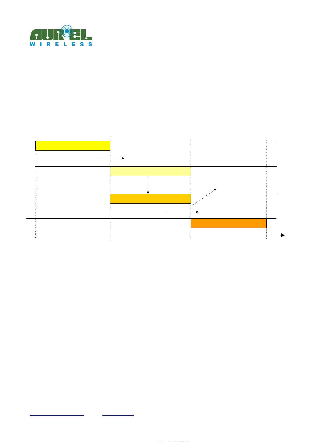
Unit A serial reception / Unit A RF transmission
Unit B RF reception / Unit B serial transmission [Fig. 3]
The lack of data at the XTR-7020A-4 module’s input is established by the expiring of a Timeout (determined
according to the speed of the data serial). Once it is off, the transceiver does not memorize further incoming
data until the RF transmission, of those already inside its reception buffer, is carried out.
The data is transmitted through an RF channel only after the serial reception is over. In the same way the
receiver analyzes the received packets from the RF, proceeding then with the serial transmission if the data is
valid or discarding them if not correct.
As shown by the Fig. 3 time diagram, the time interval, from the starting moment (instant 0) when the data
reaches the module’s port, to the moment when it is received by the remote module, is the function of the
number of Bytes that form the packet and of the serial speeds used for the reception as well as for the
transmission.
For the correct operation of the device consider that the phases contemporaneity??? inside the same unit is
not allowed; for instance : the data that possibly has entered through serial port of unit A is not memorized in
the input buffer if the same unit is in RF transmission phase.
Same thing for unit B; it is not allowed to receive RF data while the previous bytes packet is under serial
transmission.
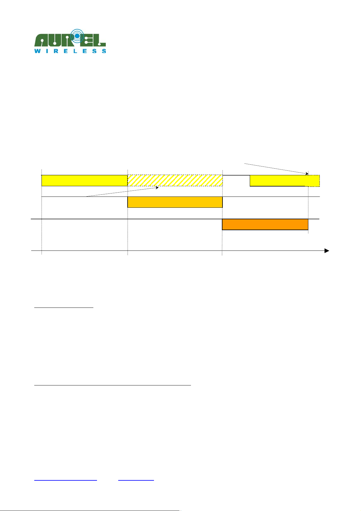
Fig. 4 shows the case of the transmission of two packets in a sequence from unit A to unit B: packet #1
enters unit A and is transmitted to unit B that forwards it through the serial port. The transmission of the
packet #2 must be carried out bearing in mind that the end of the serial reception of unit A has to take place
AFTER the end of the serial transmission of packet #1 by unit B so to avoid the overlapping of the RF
reception and of the serial transmission phases in this device: it is therefore necessary to enter a safety
interval between the transmissions of the two packets in function of the number of byte of the first packet, of
Unit A serial reception
Unit A serial STORE
0
Unit A RF FORWARD
Unit A RF transmission
adiofrequency
Unit B RF reception
Fig. 3: Store & Forward mechanism
Valid packet from unit B and
transmitted throu
Unit B serial transmission
h serial port
t [ms]
Technical specifications may be changed without notice. AUR°EL S.p.A. declines all responsabilities deriving from a wrong utilisation of the equipment.
---------------------------------------------------------------------------------------------------------------------------------------------------------------------
Tel.: +39.0546.941124 Fax: +39.0546.941660
http://www.aurelwireless.com - email: [email protected]
Dec. 20 th 2005AUR°EL S.p.A. Via Foro dei Tigli, 4 - 47015 Modigliana (FC) – ITALY
Pag 5 of 5
Page 6
+
p
0
---------------------------------------------------------------------------------------------------------------------------------------------------
PRELIMINARY
XTR-7020A-4
Owner’s Manual
[
the serial speed of unit B and in function of the time required T for the transmission of the packet on
the RF which depends upon the number of bytes of the packet and it is given by
[]
= 139.0
NKmsT ⋅
byteRF
with K=4,21 @9600bps, K=3,35 @19200bps, K=3,1 @38400 and 57600bps, K=2,8@115200bps.
The last byte of the second packet must enter unit A after unit B has ended the serial
transmission of the first packet .
Unit A serial reception packet #1
Packet #2 cannot enter unit A while the
RF transmission of packet #1 is in
rogress.
Serial data cannot be sent to unit A while the RF
transmission of the packet #1 is in progress.
Unit A RF transmission of packet #1
Fig. 4: Two data packets transmission
5. Power Down Mode
By bringing to high level (+3V) pin 16 (PWRDN), the device enters into a power saving state; the
consumption in fact is limited to less than 10 µA. In this mode, the transceiver can neither receive nor
transmit. It is necessary to commutate pin 16 to low level (0V) to bring it back to the normal operating state
(Idle mode).
In such a state the RSTX line must be maitained to the high logic level (+3V) to avoid a wrong data
transmission when the module is switched on.
6. Command Mode (XTR-7020A-4 module programming)
The Command Mode state allows the Owner to configure the operating parameters of the device. The
programming is carried out by means of ‘AT’ type commands sent to the RSTX line (pin 14) at the speed set
by means of pins SP1 and SP2 (pin 11 and 15). The module’s answers shall be given on the RSRX line (pin
12).
To enter Command Mode from Idle Mode it is necessary to send on the RSTX line (pin 14) a sequence of 3
consecutives ASCII characters ‘+’, i.e.: (+++). A module under Command Mode state is unabled to RF
reception.
RF
]
ms
Unit A serial reception of packet
#2
Unit B serial transmission of packet #1
t [ms]
Technical specifications may be changed without notice. AUR°EL S.p.A. declines all responsabilities deriving from a wrong utilisation of the equipment.
---------------------------------------------------------------------------------------------------------------------------------------------------------------------
Tel.: +39.0546.941124 Fax: +39.0546.941660
http://www.aurelwireless.com - email: [email protected]
Dec. 20 th 2005AUR°EL S.p.A. Via Foro dei Tigli, 4 - 47015 Modigliana (FC) – ITALY
Pag 6 of 6
Page 7
---------------------------------------------------------------------------------------------------------------------------------------------------
PRELIMINARY
XTR-7020A-4
Owner’s Manual
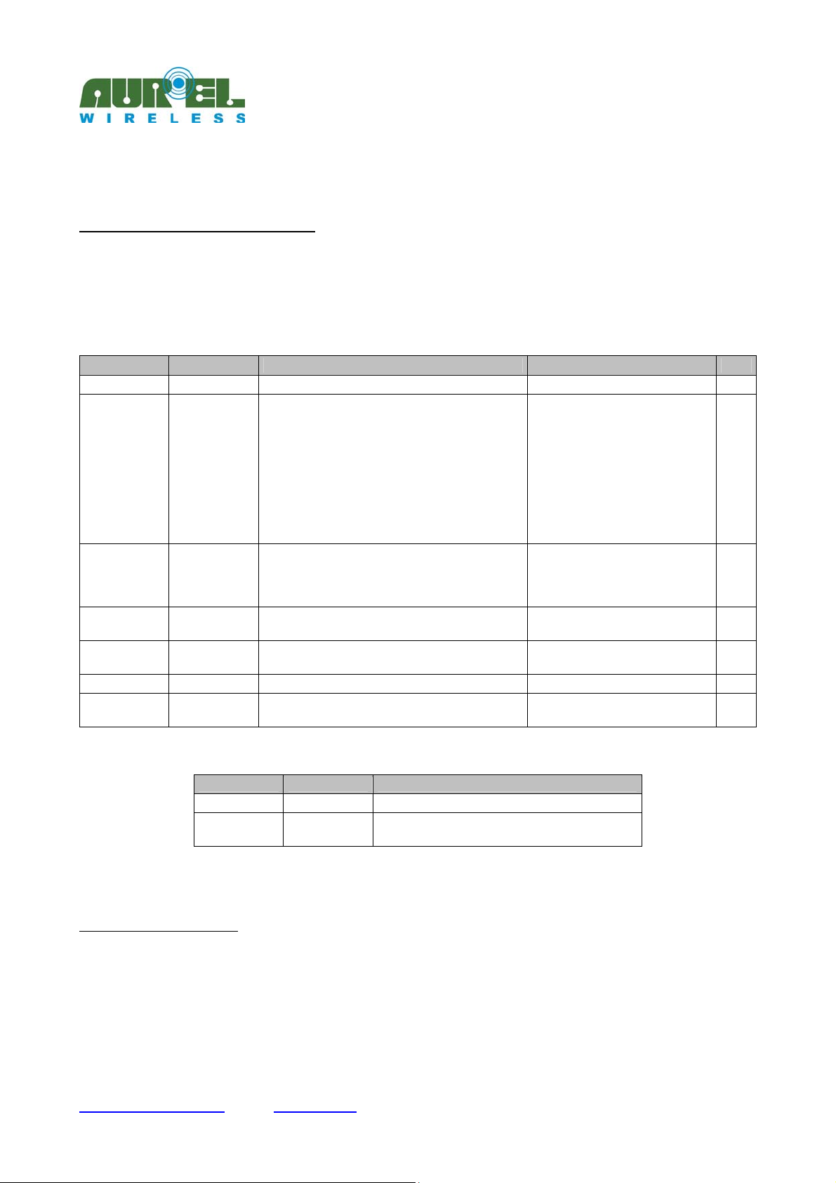
Available Registers and Commands
The commands that can be issued to XTR-7020A-4 module concern the reading and writing of the registers
containing the operation setting of the device.
The reading and writing of the configuration register and the sending of the commands to the module is
carried out by entering the ’AT’ sequence before the command’s or register’s name.
The 16 programmable registers (from S1 to S16) can be read or written according to their function.
Register Name Function Values R/W
S1 BAND
S2 CHANNEL
S3 POWER
S4 RFON
S5 SER
S15 VERSION
S16 (#) RSSI
* = default values
Command Name Function
WR WRITE
CC COMMAND
(#) Note on register S16 use
The reading of the S16 register implies the activation of an analysis procedure of the RF channel on which the module
has been programmed. Such a routine lasts for about 200ms (prefixed). The analysis result is supplied at the end of the
operation. No other operation should be carried out during such interval.
The channel analysis can be utilized whether to verify if it is already occupied by an interfering source, or to verify the
reception quality in case we intend to test the quality of an under planning connection. In this connection it is suggested
to initialize an XTR-7020A-4 module under Test Mode, to shift it in the different points where the covering has to be
Operating band of the transceiver
Operating channel
Device’s output power level
It switches On or OFF the module’s transmission
power
Selection of the serial speeds’ two benches
Code showing the firmware version
It supplies a digital indication of the power
received level, with a gradual scale from 0 to 9
CLOSE
0 = 433-434 MHz * R
0 = 433,19 MHz 3
1 = 433,34 MHz
2 = 433,50 MHz
3 = 433,65 MHz
4 = 433,80 MHz
5 = 433,96 MHz *
6 = 434,11 MHz
7 = 434,27 MHz
8 = 434,42 MHz
9 = 434,57 MHz
0 = - 8 dBm
1 = - 2 dBm
2 = + 4 dBm
3 = + 10 dBm *
0 = Power RF ON *
1 = Power RF OFF
0= ‘slow’ bench*
1= ‘fast’ bench
Variable R
0 = Min power received
9 = Max power received
Writing of the registers’ values in EEPROM
Command Mode exit
Tab. 3: Commands
R/W
3
R/W
R/W
R/W
R
3
= Channel not to be used with max power
Technical specifications may be changed without notice. AUR°EL S.p.A. declines all responsabilities deriving from a wrong utilisation of the equipment.
---------------------------------------------------------------------------------------------------------------------------------------------------------------------
Tel.: +39.0546.941124 Fax: +39.0546.941660
http://www.aurelwireless.com - email: [email protected]
Dec. 20 th 2005AUR°EL S.p.A. Via Foro dei Tigli, 4 - 47015 Modigliana (FC) – ITALY
Pag 7 of 7
Page 8

---------------------------------------------------------------------------------------------------------------------------------------------------
PRELIMINARY
XTR-7020A-4
Owner’s Manual
analyzed and then monitor the quality of the radio signal received, by reading repeatedly the S16 register of an other
XTR-7020A-4 unit, set on the same channel.
Answers to commands and operations on registers
Positive answer: OK<CR><LF>
Negative answer: <bl> ERROR<CR><LF>
Forbidden operation: <bl> NO ACCESS<CR><LF>
With <CR> Carriage Return, ASCII character 13; <LF> Line Feed, ASCII character 10; <bl> ASCII character 32.
Reading of a register
Syntax: ATSx<CR><LF> [x = 1, ...,16 register to be read]
Answer : value contained in the register if the command has been correctly issued
The registers’ value is returned, figure by figure, under ASCII value.
Example: ‘16’ is the sequence of ASCII codes 0x31,0x36, corresponding precisely to figure ‘1’ and ‘6’.
Such interpretation procedure must be followed even for the writing of a register’s value.
Writing of a register
Syntax: ATSx=Y<CR><LF> [x = 2, 3, 4 register to be written,
Answer: as indicated to para ‘Answers to commands’ above
All values programmed in the registers cause a variation of the module’s operating conditions that will be
lost once the device is switched off, unless they are saved in the EEPROM memory of the microcontroller by
means of the relevant command ATWR: in such case the modified values shall be active also to subsequent
switching on.
Command to save the registers’ value in EEPROM
Syntax: ATWR<CR><LF>
Answer: as indicated to para ‘Answers to commands’ above
Exit command from Command Mode
Syntax: ATCC<CR><LF>
Answer: as indicated to para ‘Answers to commands’ above
followed by <CR><LF>.
y = value to be entered]
Technical specifications may be changed without notice. AUR°EL S.p.A. declines all responsabilities deriving from a wrong utilisation of the equipment.
---------------------------------------------------------------------------------------------------------------------------------------------------------------------
Tel.: +39.0546.941124 Fax: +39.0546.941660
http://www.aurelwireless.com - email: [email protected]
Dec. 20 th 2005AUR°EL S.p.A. Via Foro dei Tigli, 4 - 47015 Modigliana (FC) – ITALY
Pag 8 of 8
Page 9
r
PWRDN
A
I
---------------------------------------------------------------------------------------------------------------------------------------------------
PRELIMINARY
XTR-7020A-4
Owner’s Manual
The exit from Command Mode, in absence of the ATCC command, takes place automatically after approx. 5
seconds of inactivity.
Operations
It is possible to chain several operations by mixing actions on one single register and writing or exit
commands on a single command line through the operator <,>.
In the following example the S3 register’s value is set to 2, the modification is saved and the programming
function is quitted:
Example #1: Writing of a register and value save. Exit from Command Mode
ATS3=2,WR,CC <CR><LF>
OK<CR><LF>
As it can be seen from the example, the prefix AT is applied only for the first command of the line, while for
the subsequents must be skipped. The commands chaining is possible only on one register at a time for
writing operations; if carried out along with a reading command it will engender an error answer.
Example #2: Register reading attempt and exit from Command Mode
If it is attempted to enter the command ATS1,CC<CR><LF> it will be realized that is not possible and that
the module will indicate an error when the coma is typed. The screen shall display what follows:
ATS1,<bl> ERROR<CR><LF>
The commands are not case sensitive therefore can be typed in upper or lower-case.
See Appendix A for further examples.
Application Examples
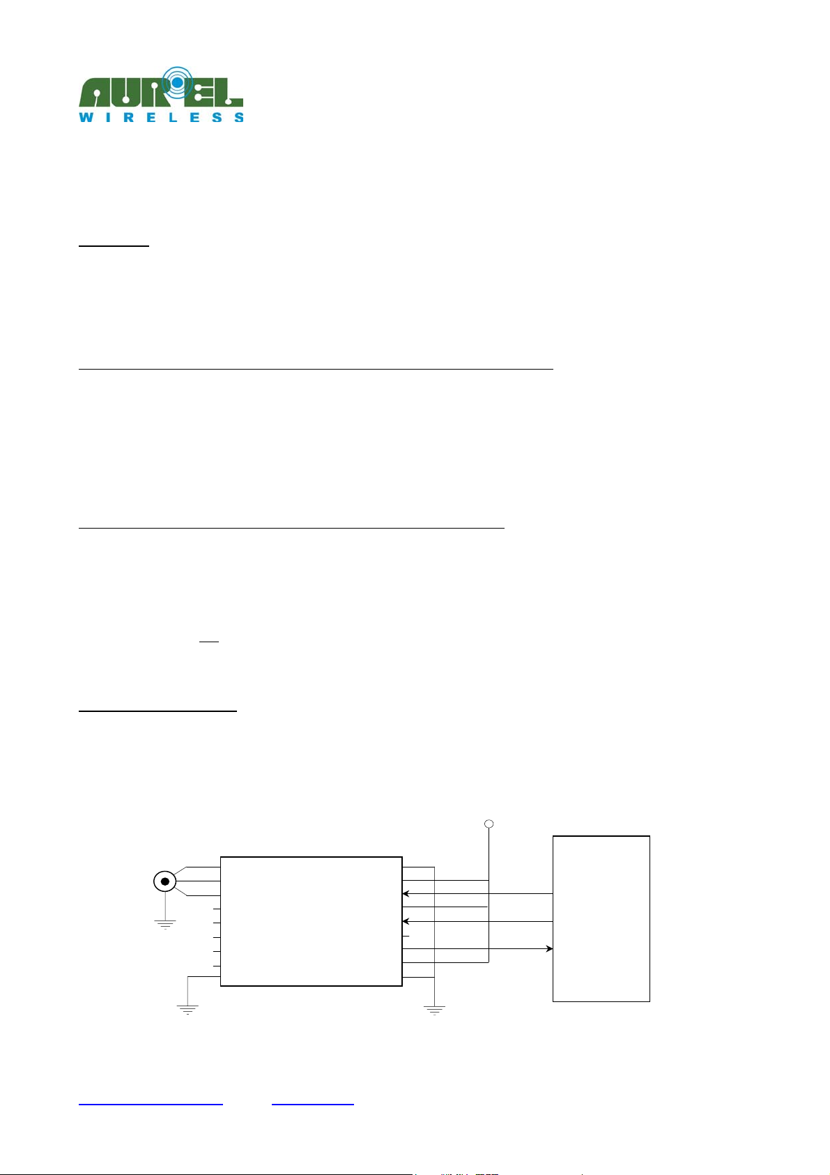
Fig. 5 shows a typical application of the XTR-7020A-4 connected to a microcontroller that, besides to
receive and transmit data on the two input and output lines (RSTX and RSRX), it drives also the PWRDN.
1 RF GND
2
ntenna
3 RF GND
9 GND
XTR-7020A-4
GND 18
Vcc 17
16
SP2 15
TXD 14
RXD 12
GND 10
Microcontrolle
OUT PORT
OUT PORT
N PORT
Technical specifications may be changed without notice. AUR°EL S.p.A. declines all responsabilities deriving from a wrong utilisation of the equipment.
---------------------------------------------------------------------------------------------------------------------------------------------------------------------
Tel.: +39.0546.941124 Fax: +39.0546.941660
http://www.aurelwireless.com - email: [email protected]
Dec. 20 th 2005AUR°EL S.p.A. Via Foro dei Tigli, 4 - 47015 Modigliana (FC) – ITALY
Pag 9 of 9
Page 10
N
P
N
A
---------------------------------------------------------------------------------------------------------------------------------------------------
PRELIMINARY
XTR-7020A-4
Owner’s Manual
Fig. 5: Example of a 9600 bps connection (SP1 and SP2 to Vcc) between a XTR-7020A-4 and a
microcontroller
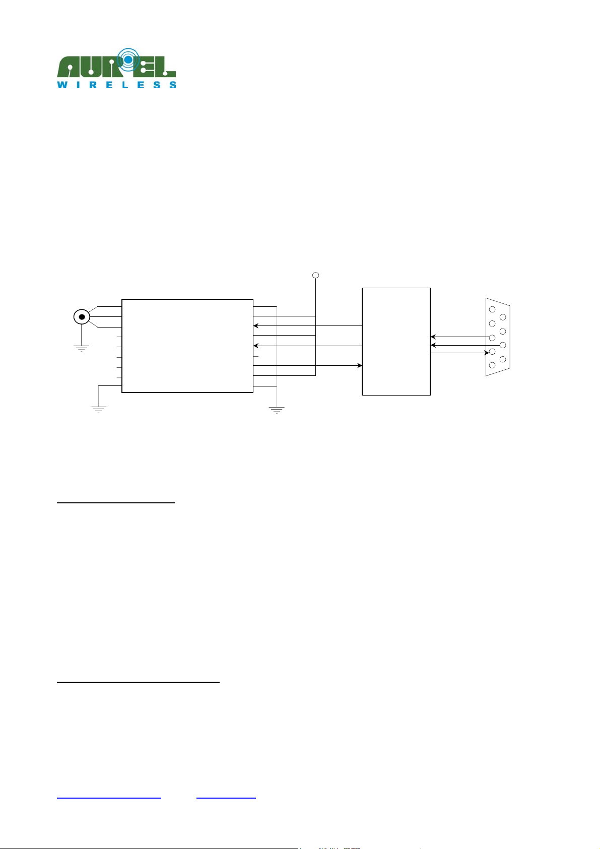
Fig. 6 shows an example of connection between an XTR-7020A-4 module and the serial port of a PC: the
integrated circuit interposed between the transceiver and the port, performs only the conversion function
between the electrical levels of the RS-232 and the TTL logic.
By means of the RTS signal (pin 7 of the DB9 port) it is possible to drive the PWRDN line, while the serial
speed selection is fixed to 9600 bps.
1 RF GND
2
ntenna
3 RF GND
XTR-7020A-4
GND 18
Vcc 17
WRD
SP2 15
TXD 14
RXD 12
16
MAX-232
9 R2OUT
12 R1OUT
10 T2I
R1IN 13
9 GND
GND 10
DB9
Fig. 6: Example of the connection between an XTR-7020A-4 and the serial port RS-232 at 9600 bps (SP1
and SP2 to Vcc)
Standards of reference
The XTR-7020A-4 transceiver complies with European Standards EN 300 220, and EN 301 489. The tests
are carried out transmitting and receiving Pseudo Random (CEPT 70-03) Codes. The occupation band is
verified by using a Pseudo Random Code at 115200 bps. Besides, the product has been tested according to
EN 60950 Standards and it is utilized inside a special isolated case which guarantees its compliance to the
above mentioned Standards. The transceiver must be fed by a very low voltage and safety source protected
against short circuits.
The usage of the transceiver module is foreseen inside cases that guarantee the compliance to EN 61000-4-2
Standards not directly appliable to the module itself. In particular, is left to user’s care the isolation of the
connection to the outdoor antenna and of the antenna itself since the RF output of the receiver is not in the
position to directly bear the electrostatic charges foreseen by the a.m. standards.
CEPT 70-03 Reccommendation
The XTR-7020A-4 transceiver operates in a harmonized frequency band therefore, in order to comply with
the current regulations; the device must be utilized in the time scale, for a maximum hourly duty-cycle of
10% (equal to 6 minutes of use over 60).
Technical specifications may be changed without notice. AUR°EL S.p.A. declines all responsabilities deriving from a wrong utilisation of the equipment.
---------------------------------------------------------------------------------------------------------------------------------------------------------------------
Tel.: +39.0546.941124 Fax: +39.0546.941660
http://www.aurelwireless.com - email: [email protected]
Dec. 20 th 2005AUR°EL S.p.A. Via Foro dei Tigli, 4 - 47015 Modigliana (FC) – ITALY
Pag 10 of 10
Page 11
---------------------------------------------------------------------------------------------------------------------------------------------------
PRELIMINARY
XTR-7020A-4
Owner’s Manual
The antenna suggested solution (loop antenna) guarantees the compliance with the regulation concerning the
irradiated power.
M
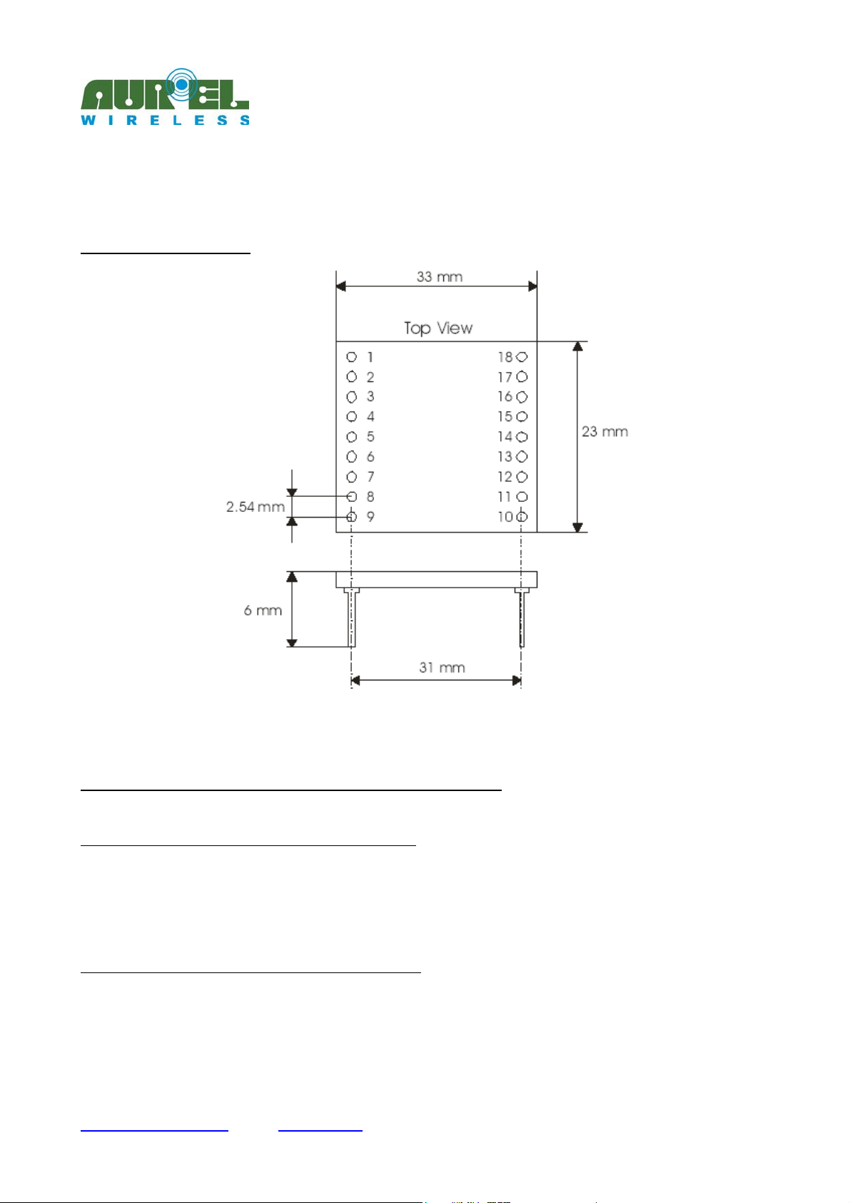
echanical dimensions
XTR-7020A-4
Fig. 7: Mechanical dimensions
Appendix A – More examples of operations with registers
Example #3: reading of the module’s operating band
+++OK <CR><LF>
ATS1 <CR><LF>
0 <CR><LF> [0= 433-434 MHz band]
Example #4: variation of the module’s operating band
+++OK <CR><LF>
ATS1=2 <CR<LF>
<bl> NO ACCESS<CR><LF>
Technical specifications may be changed without notice. AUR°EL S.p.A. declines all responsabilities deriving from a wrong utilisation of the equipment.
---------------------------------------------------------------------------------------------------------------------------------------------------------------------
Tel.: +39.0546.941124 Fax: +39.0546.941660
http://www.aurelwireless.com - email: [email protected]
Dec. 20 th 2005AUR°EL S.p.A. Via Foro dei Tigli, 4 - 47015 Modigliana (FC) – ITALY
Pag 11 of 11
Page 12

---------------------------------------------------------------------------------------------------------------------------------------------------
PRELIMINARY
XTR-7020A-4
Owner’s Manual
Syntax error: the S1 register is available for reading only
Example #5: Channel reading
+++OK <CR><LF>
ATS2 <CR><LF>
2 <CR><LF> [2= 433.5 MHz channel]
Example #6: Channel selection
+++OK <CR><LF>
ATS2=8 <CR><LF> [8= 434,42 MHz channel]
OK <CR><LF>
Example #7: Output power reding
+++OK <CR><LF>
ATS3 <CR><LF>
1 <CR><LF> [1= power –2dBm]
Example #8: Output power selection
+++OK <CR><LF>
ATS2=3 <CR><LF> [3= power +10dBm]
OK <CR><LF>
Example #9: Reading of the received signal
+++OK <CR><LF>
ATS16 <CR><LF>
9 <CR><LF> [9 = busy channel, maximum received power]
Example #10: Reading of the received signal
+++OK <CR><LF>
ATS16 <CR><LF>
0 <CR><LF> [free channel, minimum received power]
Technical specifications may be changed without notice. AUR°EL S.p.A. declines all responsabilities deriving from a wrong utilisation of the equipment.
---------------------------------------------------------------------------------------------------------------------------------------------------------------------
Tel.: +39.0546.941124 Fax: +39.0546.941660
http://www.aurelwireless.com - email: [email protected]
Dec. 20 th 2005AUR°EL S.p.A. Via Foro dei Tigli, 4 - 47015 Modigliana (FC) – ITALY
Pag 12 of 12
 Loading...