

Page 1
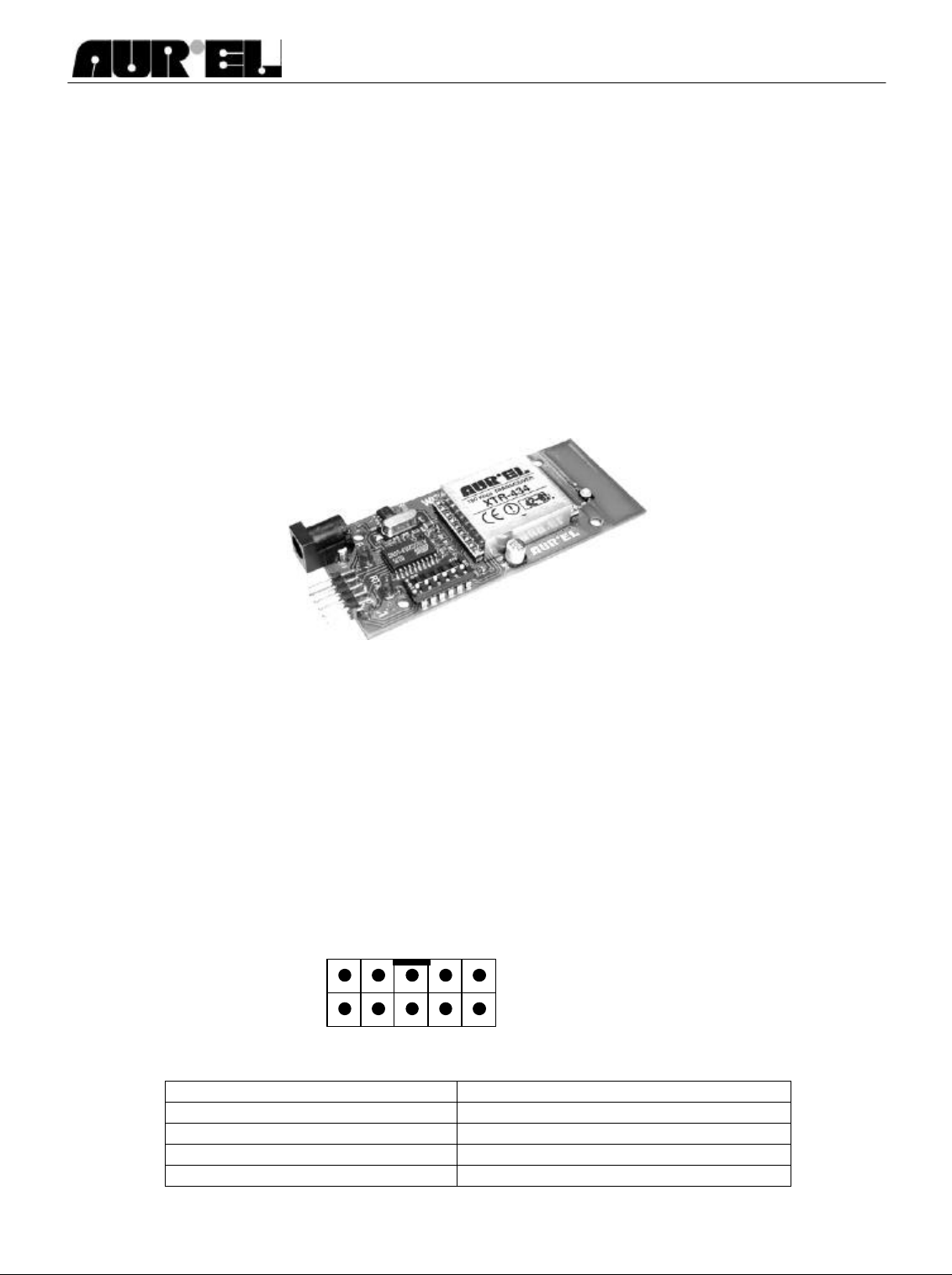
WIZ-SML-IA
Front view
1 2 9
10
Instruction Manual
Data transmission by the WIZ-SML-IA module
The WIZ-SML-IA modules are transceivers for point-to-point data transfer in half-duplex mode. They are the
right solution for all those applications in which the so called “virtual cable” has to be implemented, i.e. the
RF connection of two systems with RS232 output (for instance two PCs.) The WIZ-SML-IA module is
available in 12V and 5V version: in the first case the voltage is supplied by a connector with central positive
Vcc, while in the 5V version the voltage is supplied through the input 10 of the data connector. Connected to
the module can be used W232 ADAPTER connector which foresees inside an integrated circuit which shall
care for the conversion of the electric signals from RS232 logic to TTL logic and vice versa.
The module has very small dimensions (4 x 9 cm only) and in its card integrates a 100 kbps XTR transceiver,
a microprocessor which administrates the RF syncronizing protocol and a tuned antenna realized on a
printed circuit. Besides these components is fitted also a confirguration dip- switch with 6 positions and 2
indication LED (supply and operation).
The module is enclosed in a special case which complies with the EN 61000-4-2 rule.
Module’s 12 V supply
By means of a connector with positive pole at central pin, 9V-15V DC voltage supply
Module’s 5V supply
Input no. 10 of the data connector (see below).
Data connector
1. TX Data (IN) 2. XTR analogic output (OUT)
3. GND 4. GND
5. RX Data (OUT) 6. XTR Carrier Detect (OUT)
7. CTS not in use (OUT) 8. LED (OUT)
9. RTS not in use (IN) 10. 5V DC (IN/OUT)
Technical features are subject to change without notice. AUR°EL S.p.A does not assume responsibilities for any damage caused by the device’s misuse.
Page 2
WIZ-SML-IA
Instruction Manual
The connector's references have the following meanings:
[1] TX Data In. Logic level 0 - 5 V. Data incoming under RS232 format with
1 start bit, 8 data bit, 1 stop bit.
The start bit is given by the transition high-low (5v-0v)
[2] XTR analogic output.
Output analogic signal with approx. 0.5 Vpp in presence of a modulating signal. Should any useful
signal not available, an inchorent noise, with p.p. level greater than the signal itself, must be
present. D.c. level about 1.8V.
[5] RX Data out.
0 - 5V logic level. Outgoing data under RS232 format, same as for the input data.
Usually, the logic level is high (5V) but it goes down (0V) at the start bit.
[6] Carrier Detect.
Normally high (5V) it goes down in presence of a received radio frequency. There is no difference
between useful signal and noises, therefore it is a non selective chanel occupation signal. The
minimum information level varies from -96dBm at the maximum sensitivity, therefore it is not safetly
usable if the receiver is demanded to operate anyhow at its maximum sensitivity.
[7] CTS : not in use in this version.
[8] Auxiliary LED. It shows an Rx/Tx activity. It is the pilot signal of the internal LED
[3], [4] GROUND
[10] 5V DC
In the 5V supplied module this is the stabilized voltage input, while in the 12V supplied module it is
used as output channel to supply the integrated circuit of the W232 ADAPTER.
Dip-Switch
• DS1-DS2: Tx/Rx serial gate speed
DS1 DS2 Speed
Open Open 9600
Open Close 19200
Close open 57600
Close Close 115200
• DS3: if closed all the received bytes, even not correctly decoded, are forwarded through the serial
gate; if open the checksum verification is activated and the data packet is forwarded only if detected
valid.
• DS4: not assigned.
• DS5: not assigned.
• DS6: in use during calibration operation only. Do not modify.
All configuration changes, by means of the dip switches, must be carried-out when the module is switched
off.
AUR°EL S.p.A. Via Foro dei Tigli, 4 - 47015 Modigliana [FC] – ITALY Rev. A, 01-04-2002
Tel.: +390546941124 – Fax: +390546941660 Pag 2 di 3
http://www.aurel.it - email: [email protected]
Technical features are subject to change without notice. AUR°EL S.p.A does not assume responsibilities for any damage caused by the device’s misuse.
Page 3

WIZ-SML-IA
Instruction Manual
Module usage
The RS232 connection takes place without parity control, 1 START bit, 8 DATA bit, 1 STOP bit. Before
forwarding the information to the RF, the User’s software must reduce it to packet not bigger than 96 bytes.
End Bytes are not required since the WIZ-SML-IA module considers an incoming string
terminated only when, for a 1.5 Byte time long, (and anyhow not less than 0,5 mS), no other
incoming Bytes are detected at the serial gate; this means that the Timeout's lapse varies
according to the Baud Rate speed chosen, by varying from a maximum of 1.6 mS (@ 9600 b/S)
to a minimum of 0.5 mS (@ 115200 b/S).
The RF transmission starts when the incoming data string is terminated.
Before sending a new data packet to the serial gate it is necessary to wait till the previous packet’s RF
transmission is over. All data entering the serial gate during the RF transmission forwarding phase, are
bound to be irremediably lost.
It is therefore suggested to the User that, during the administration software writing, to pay very much
attention to a correct timing of the data packets going out from the PC’s serial gate, specially when the
packets’ length is variable. Infact, if it is decided to forward a long packet followed by a short one, it is
necessary to wait all the time required by the RF transmission of the long packet before sending, to the
serial gate, the short one.
The packet's RF transmission time T is given by:
T = 3.6 mS + (NumByte+2) x 0.156 mS
Example #1 - Packet lenght: 1 Byte
Transmission time T= 4.1 milliseconds
Example #2 - Packet lenght: 32 Byte
Transmission time T= 8.9 milliseconds
Example #3 - Packet lenght: 96 Byte
Transmission time T= 18.9 milliseconds
It is suggested to add, precautionally, few mS to the RF transmission time between the dispatch of a packet
and the subsequent one.
The WIZ-SML-IA module is usually kept in RF reception and, once the incoming string reception is over, its
forwarding transmission takes place immediately through the serial gate (pin 5 of the Data Connector).
If the dip-switch 3 is in "close" position the forwarding transmission takes place even if errors are detected
on the single Bytes, while, if it is in "open" position the forwarding takes place exclusively if the checksum is
valid.
AUR°EL S.p.A. Via Foro dei Tigli, 4 - 47015 Modigliana [FC] – ITALY Rev. A, 01-04-2002
Tel.: +390546941124 – Fax: +390546941660 Pag 3 di 3
http://www.aurel.it - email: [email protected]
Technical features are subject to change without notice. AUR°EL S.p.A does not assume responsibilities for any damage caused by the device’s misuse.
 Loading...