

Page 1
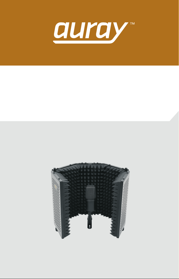
Refl ection Filter
RF-5P-B
Owner’s Manual
Page 2

2 RF-5P-BOwner’s Manual
Introduction
Thank you for choosing Auray.
Congratulations on your purchase of the Auray RF-5P-B Refl ection Filter.
Ideal for voice recording in a room that does not have acoustic treatment, the
RF-5P-B is designed to absorb and help isolate the microphone from
unwanted ambient refl ections.
When recording vocals in an acoustically untreated room like a bedroom,
living room, or project studio, the vocals bounce o the walls, fl oor, and
ceiling, and are picked up by the microphone. These early refl ections
interfere with the sound of the voice, producing a roomy and distant e ect
that presents challenges during the mixing process and in live broadcasts.
The RF-5P-B helps absorb and di use these unwanted refl ections, creating a
closer and dryer sound that allows more control over the vocals. It can also be
used for isolating vocals in a rehearsal studio or for other applications, such
as recording an acoustic guitar or an electric guitar cabinet.
Five punched metal panels and a pyramidal, acoustic foam lining fi lter
ambient noise and help prevent sound from refl ecting back into the
microphone. The two outermost panels are adjustable, allowing you to
control how dry your recording will be.
The RF-5P-B is easy to set up and comes with three di erent mounting
options. The threaded socket on the bottom can be mounted onto a standard
microphone stand or you can use the clamps on the back to mount it to the
shaft of a microphone stand with a boom arm. The RF-5P-B also comes with
non-slip feet for tabletop use.
Page 3
3RF-5P-B Owner’s Manual
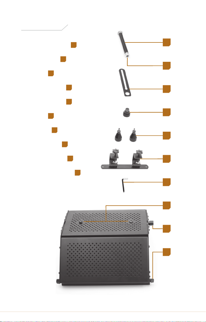
Microphone stand
1
Thumbscrew
2
Bracket
3
Male thumb nut
4
Non-slip feet (2)
5
Clamps
6
Allen key
7
Clamp screws
8
Threaded socket
9
Panel locking knobs
10
Overview
1
3
4
5
6
7
9
8
10
2
Page 4
4 RF-5P-BOwner’s Manual
Mounting the RF-5P-B onto a Microphone
Stand’s Threaded Mount
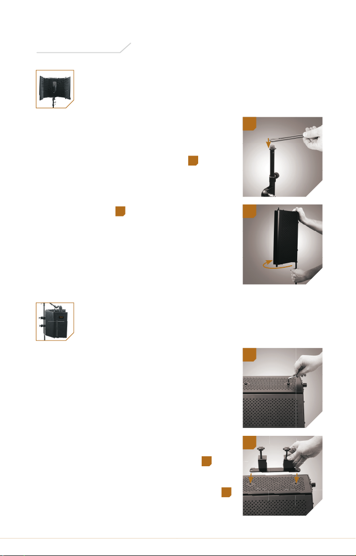
To mount your RF-5P-B on the threaded mount
of a microphone stand, follow these steps:
1. Fit the hole in the bracket onto the threaded
mount of the microphone stand.
1
2. Align the refl ection fi lter’s threaded socket
with the microphone stand’s threaded
mount, and screw the refl ection fi lter on
until secure.
2
With this kind of setup, you can mount your
microphone onto the bracket (see Setting Up
Your Microphone on the Bracket).
Mounting the RF-5P-B on a Microphone
Stand Shaft
If your microphone stand has a boom arm, you
can mount the RF-5P-B on the microphone stand
shaft and position the boom arm and
microphone to reach over and into the fi lter. This
kind of setup will give you greater options for
microphone placement.
To mount your RF-5P-B on a microphone stand
shaft, follow these steps:
1. Use the hex key to unscrew the hex screws
from the back of the refl ection fi lter.
3
2. Align the sockets in the clamps with the
sockets in the back of the refl ection fi lter.
4
Instructions
3
2
1
4
Page 5
5RF-5P-B Owner’s Manual
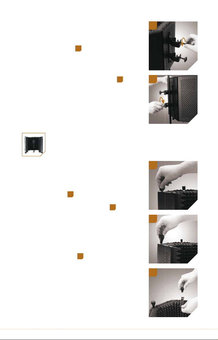
3. Use the hex key to screw the hex screws into
the sockets until secure.
4. Loosen the clamps by unscrewing the
clamp screws.
5
5. Fit the clamps around the microphone stand
shaft.
6. Tighten the clamps until secure.
6
You can adjust the vertical placement of your
RF-5P-B by slightly loosening the clamps and
repositioning the unit higher or lower on the
microphone stand.
Using Your RF-5P-B on a Desk
or a Table
You can use the included feet to place your
RF-5P-B Refl ection Filter on a desk or table. To
install the feet, follow these steps:
1. Unscrew the bottom locking knob on one of
the panels.
7
2. Screw in the foot until secure.
8
3. Repeats steps 1 and 2 to install the other
foot.
4. If necessary, attach the bracket by fi tting
it around the male thumb nut and screwing the nut into the threaded socket of the
refl ection fi lter.
9
9
7
8
5
6
Page 6
6 RF-5P-BOwner’s Manual
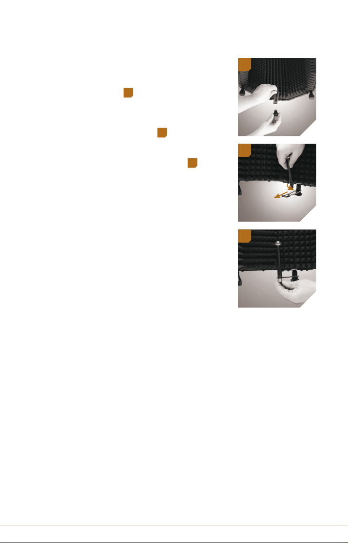
Setting Up Your Microphone on the Bracket
1. If necessary, attach the bracket by fi tting it
around the male thumb nut and screwing
the nut into the threaded socket of the
refl ection fi lter.
10
2. Insert the small thread of the microphone
stand into the wide end of the slot and slide
it to the desired position.
11
3. Screw on the thumbscrew to secure the
microphone stand to the bracket.
12
4. Mount your microphone onto the
microphone stand. For more information
about mounting your microphone, consult
your microphone’s user manual.
Tip: You can slightly loosen the thumb nut and
the thumbscrew to adjust the horizontal
placement of your microphone. When your
microphone is in the desired position, retighten
until secure. See Positioning the Microphone for
more information on this topic.
Adjusting the Panels
Although the most common position for the panels is to be open, it can
be useful to close them slightly in order to absorb more sound from
inside the fi lter and isolate and reduce more ambient noise from outside
the fi lter. The more closed the panels are, the more dry your sound
will be.
You can also close the panels all the way for convenient storage or
transport.
To adjust the panels, unscrew the locking knobs on the top and bottom
hinges just enough to swing the panels to the desired positions.
Retighten the locking knobs until secure.
12
10
11
Page 7

7RF-5P-B Owner’s Manual
Specifi cations
!
Warnings
Positioning the Microphone
It is usually most desirable to place the microphone directly in the center
of the refl ection fi lter in order to reduce the most amount of ambient
noise. You can also adjust the microphone placement in the fi lter to
produce a creative e ect. For example, you can move the microphone
away from the rear panel to let in more ambient noise for a more open
sound. We encourage you to experiment on your own.
Dimensions: 15.8 × 12.6 × 10.2 in. (400 × 320 × 260 mm)
Weight: 9.5 lb. (4.3 kg)
Before using your RF-5P-B, please read the following safety notices
carefully and thoroughly to ensure safe use and to help prevent damage
to your refl ection fi lter.
• Please read and follow these instructions, and keep this manual in a
safe place.
• Do not attempt to disassemble or repair the equipment
—doing so will void the warranty, and Auray will not be responsible
for any damage.
• Handle the unit with care.
• Make sure everything is secure before proceeding.
• Make sure the item is intact and that there are no missing parts.
• To avoid damage to your refl ection fi lter, be careful not to
overtighten or improperly thread any threaded fi ttings, such as
bolts and locking knobs.
• All photos are for illustrative purposes only.
Page 8

Warranty
Auray provides a limited warranty that this product is free from defects in
materials and workmanship to the original purchaser under normal use for
a period of one (1) year from the original purchase date or thirty (30) days
after replacement whichever occurs later. Our responsibility with respect to
this limited warranty shall be limited solely to repair or replacement, at its
option, of any product which fails during normal consumer use.
To obtain warranty coverage during the Warranty Period, contact your place
of purchase (“Seller”) to obtain a return merchandise authorization (“RMA”)
number, and return to Seller the defective product along with proof of
purchase and the RMA number.
This warranty does not extend to damage or failure which results from
misuse, neglect, accident, alteration, abuse, improper installation or
maintenance. EXCEPT AS PROVIDED HEREIN, AURAY MAKES NEITHER ANY
EXPRESS WARRANTIES NOR ANY IMPLIED WARRANTIES, INCLUDING BUT
NOT LIMITED TO ANY IMPLIED WARRANTY OF MERCHANTABILITY OR
FITNESS FOR A PARTICULAR PURPOSE. This warranty provides you with
specifi c legal rights, and you may also have additional rights which vary from
state to state.
www.AurayAudio.com
© Copyright 2012 Gradus Group
 Loading...