

Page 1
Page 2

Contents / Introduction
Contents Contents
Introduction
Applications
Type Designation
Multi-turn Actuators
Design Principle
Functions
Open-Close Duty
Regulating Duty
Limit Switching
Torque Switching
Control Equipment
Micro Switches
Reduction Gear Unit
Position Indicators
Intermediate Switch
2
3
4
5
6-7
8
8
8
9
10
11
11
12
12
13
General
Data Sheets
Technical Data Open-Close Duty
Electrical Data Open-Close Duty
Technical Data Regulating Duty
Electrical Data Regulating Duty
Dimension Sheet, Norm
Dimension Sheet, Compact
Dimension Sheet, E-pac
Output Drives
Linear Thrust Unit
Terminal Plan (Norm)
Wiring Diagram (Integral Starter)
Legend - Integral Starter
29
30-31
32-33
34
35
36
37
38
39
40
41
42
43
Manual Operation
Top Bevel Gear Set
Space Heater
Motors
Actuators for Regulating Duty
Actuator Types
Auma Norm Actuators
Auma Integral Starter Actuators
Control Versions
Auma Compact
Auma e-pac
Interface
Valve Attachment
Output Drives
Electrical Connection
Actuator Gearbox Combination
Service Conditions
13
13
13
14-15
16-20
21
21
21
22
22
23
24
24
24
25
26
27
Introduction
In the course of ever increasing demand for
automation in all sectors of industries, electric
actuators for process control and regulation
have become more and more important. For
more than 30 years, Auma concentrates on
design, development and manufacturing of
electric actuators. During this period, Auma
has acquired a know-how in this field that can
hardly be surpassed. Auma today is one of the
leading manufacturers of electric actuators in
the world.
Auma India (Ltd.,) is now a subsidiary of
Auma Werner Riester Gmbh & Co. KG,
Germany manufacturing electric actuators
under brand name . Auma (India) Ltd.,
started its operations in the year 1985 with HQ
and sophisticated manufacturing base at
Bangalore.
Enclosure Protection
Ambient Temperature
Explosion Proof
2
27
27
28
Sales support and after sales service are
provided by network consisting of regional
offices & service centers.
Page 3

Auma multi-turn actuators of the type range SA
can be used wherever the automation of the
valve is required. The adoption to the
requirements of nearly every valve automation
task is possible. This is on account of :
An extermely wide torque range
Various combination possibilities with
Auma Valve Gear boxes. Thereby the torque
range can be further extended and / or the
multiturn actuator can be converted into
part turn, lever or linear actuator.
A large variety of versions, whether for open
or closed loop control, explosion proof
applications, a suitable version is available.
Energy
Power Plants
Air Pollution Control
District Heating
Pipelines
Applications
Water / Waste Water
Water Works
Water Pipelines
Sewage Treatment
Pump Stations
Locks / Dams
Chemical Industry
Petro-chemical
Chemical
Pharmaceutical
Others
Air Conditioning
Steel Mills
Ship Building
Cement Plants
Food Industry
3
Page 4

Type Designation
Actuator
Types
Torque Ratings
Auma
Norm
Auma
Integral Starter
Auma
Flame Proof /
Explosion Proof
3 m kg
6 m kg
12 m kg
15 m kg
25 m kg
30 m kg
50 m kg
60 m kg
100 m kg
OPEN-CLOSE Duty
Regulating Duty
Auma
Compact
Auma
e-pac
Expl. Proof
Norm
Expl. Proof
Compact
OPEN-CLOSE Duty
Regulating Duty
OPEN-CLOSE Duty
Regulating Duty
OPEN-CLOSE Duty
Regulating Duty
OPEN-CLOSE Duty
Regulating Duty
Output Drives
Model : SA
Model : SAR
Model :SA Compact
Model : SAR Compact
Model :SA e-pac
Model : SAR e-pac
Model :SAEx
Model : SAREx
Model :SACEx
Model : SARCEx
A Stem nut
B Plug Sleeve
C Dog Coupling
D Stub Shaft
E Bore with Keyway
Type Designation : Example
Model
Torque Rating
Output Speed
SA A12 22
4 rpm
5.6 rpm
8 rpm
11 rpm
16 rpm
22 rpm
32 rpm
45 rpm
63 rpm
90 rpm
125 rpm
180 rpm
Output Speed in RPM
Output Drive
4
Page 5

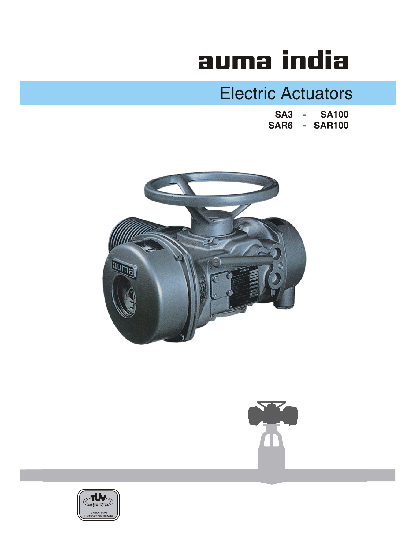
Multi-turn Actuator SA3 - SA100
Torque range 3 m kg to 100 m kg
Output speed 4 rpm to 180 rpm
Multi-turn Actuators
Multi-turn Actuator
Integral Starter - Compact
Multi-turn Actuator
Integral Starter - e pac
Multi-turn Actuator
Flame Proof / Explosion Proof
5
Page 6

Design Principle
Manual Operation
Motor
Change Gears
Terminal
Compartment
Reduction Gearing
Valve Attachment
Switch Compartment
6
Page 7

Motor Terminal Compartment
Design Principle
Especially high starting torque is frequently
required to unseat valves from end positions.
The motors developed by Auma fulfil this
basic requirement.
Change Gears Valve Attachment
Auma actuators are driven by special
combination of gears which are outside the
grease filled housing & require no lubrication.
If required, output speed can be easily altered
by changing the gear pair and / or motor at
site.
Reduction Gearing Manual Operation
A well proved principle of worm gearing is
used to reduce the motor speed to required
output speed of actuator. Self-locking feature
is achieved by worm gearing upto 90 output
rpm. Worm shaft and output shaft with worm
wheel run in ample sized bearings. The sliding
worm is positioned between two sets of
springs on worm shaft. The worm moves
axially in relation to thrust which is the
measure for torque. Via lever & gears the
torque is transmitted to control unit.
All electrical connections are terminated inside
the terminal compartment. Screw type terminals
are provided for easy connections. Multi-pin
plug-socket connector can be provided for ease
of connections & maintenance.
The mounting flange is according to ISO 5210 /
DIN 3210. Various output drives are available for
for adaption to various types of valves.
For commissioning or in an emergency, actuator
can be operated with hand wheel. When starting
the motor, the manual drive is automatically
disengaged.
Switch Compartment
Depending upon type of valve, the actuator
must be switched off at end positions by limit
switch or torque switch. For this purpose,
independent limit switching or torque
switching devices are provided in the switch
compartment. The switching devices are easily
accessible for any setting at site.
7
Page 8
Functions
Open Close Duty
The characteristic feature of this actuator is
open loop. The normal valve positions in
OPEN-CLOSE Duty are end positions OPEN
and CLOSED. After receiving command, the
actuator operates the valve to one of the end
positions or if necessary to a preset
intermediate position. The valves are operated
relatively seldom, the time intervals can span
between a few minutes to several months.
Auma multi-turn actuators type SA for open
close service are rated for short time duty
S2-15min.
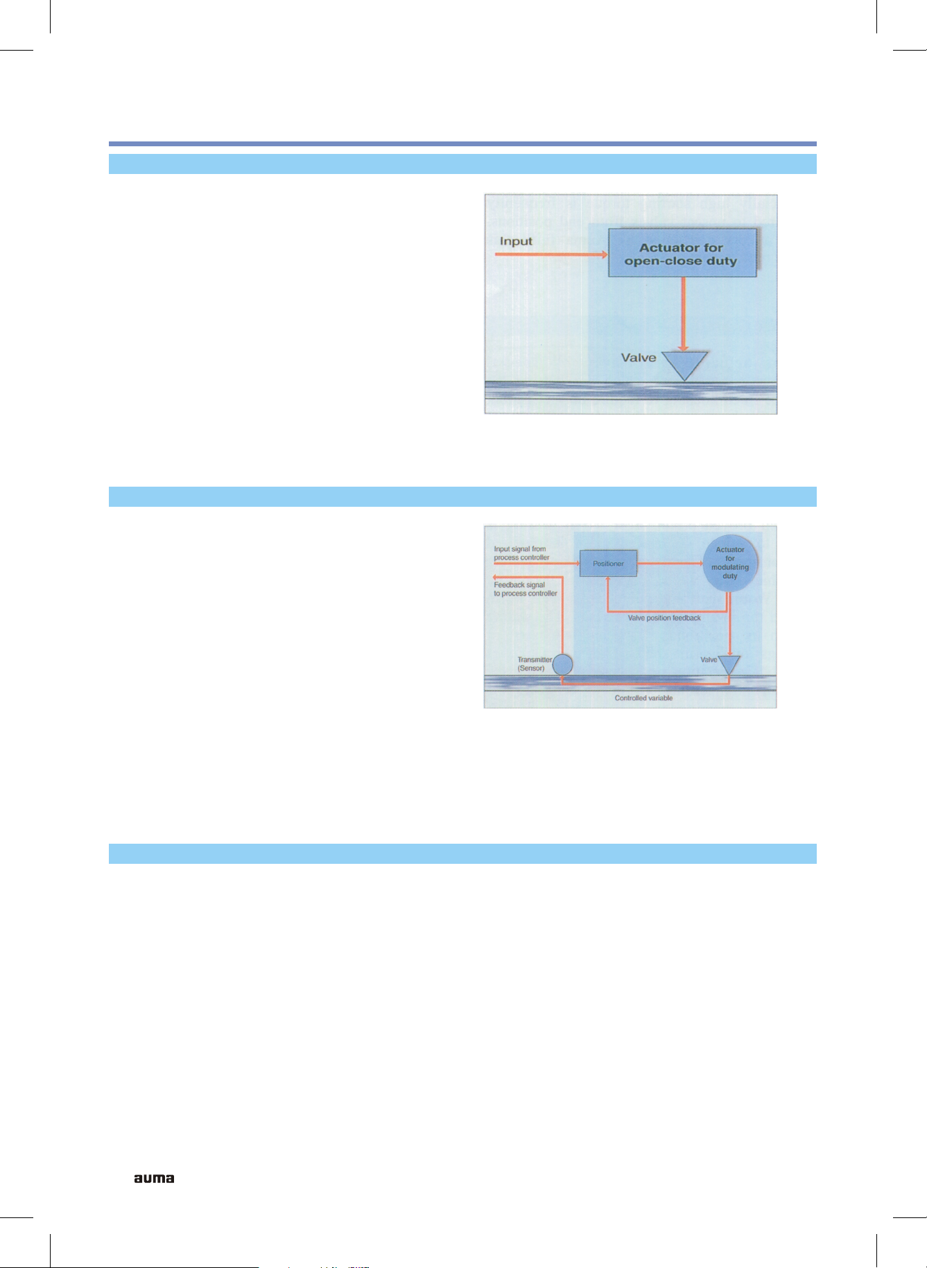
Regulating / Modulating Duty
Typical Characteristics of
OPEN-CLOSE DUTY
The characteristic feature of this actuator is
closed loop in which input command signal to
actuator is directly influenced by the flow
through the valve. Regulating / Modulating
duty actuator SAR operates between two set
bands between open-close positions depending
upon actual valve position and feedback signal.
The motors of these actuators are rated for
intermittent duty S4-25%. The mechanical
components and motor are designed to withstand
a large number of operations required for
modulating applications.
Typical Characteristics of
Regulating / Modulating Duty
Pemissible number of starts-stops depends upon
actuator size & speed. The details are available
in Data Sheets.
Short Time and Intermittent Duty IS 12824
Short time Duty S2 Intermittent Duty S4
Operation at constant load during a given
time, less than that required to reach thermal
equilibrium, followed by a rest and deenergized period of sufficient duration to reestablish machine temperatures within 2 C.
o
A sequence of identical duty cycles, each cycle
including a significant period of starting, a period
of operation at constant load and a rest and deenergized period. These periods being too short
to attain thermal equilibrium during one duty
cycle.
The duration of short time is limited to 15, 30
or 60 min.
The relative on time at S4-25% is limited to
25% of the cycle time.
8
Page 9

Limit Switching
Functions
The limit switching enables to switch off the
actuator when reaching defined valve
position, usually end positions. The valve
travel is measured by mechanical counter gear
mechanism which when reaching the set
Two Train Counter Gear
For Two train counter gear, two limit switches,
one for each direction of travel having 1 NO
+ 1 NC or 2 NO + 2 NC contacts are provided.
The number of spindle turns can be set
between 1 and 480 or 1 and 4800.
switching points operate the electrical limit
switches by cams. The setting accuracy is 1/10 of
a turn of actuator output shaft.
In limit switching, two train counter gear and
four train counter gear versions are available :
Four Train Counter Gear
If limit switching is required at two end
positions only, two train counter gear is used.
However, if two additional intermediate
switching positions are desired, Four Train
Counter Gear is required. This limit switching
has 4 counter gears and 4 micro switches. Two
counter gears are used to switch off at end
positions as in Two Train Counter Gear. The
other two are available for setting any desired
intermediate positions between end positions.
After cam actuation, the switches remain
actuated till reaching end of valve travel.
Examples of such application are :
To stop at intermediate position
Sequence control, that is to start
another equipment like pump or bypass
valve actuator after certain travel
of valve.
Two Train Counter Gear
The accuracy of setting is 1/10 of a turn of
actuator output shaft. For four train counter
gear, 4 limit switches of 1 NO + 1 NC or 2 NO
+ 2 NC contacts are provided.
Four Train Counter Gear
9
Page 10
Functions
Torque Switching
The torque switching enables to switch off the
actuator when pre-determined torque is
reached instead of a defined position. The
torque switching works on principle of sliding
worm.
Axial displacement of worm proportional to
thrust is transmitted to torque switches.
Torque switches operate in closing & opening
directions. The required tripping torque can be
easily set on the graduated dial. If limit switch
cut off is selected prior to torque switch, then
torque switch serves as overload protection.
For tight seating of certain valves, the actuator
must be operated to end position CLOSED
with defined force. Such operation can be
carried out by torque seating. Limit seating is
commonly used in the end position OPEN.
Running Indication
Blinker switch is provided in the actuator and
can be used as running indicator.
Torque Switching
When torque seating is used at end position,
limit switches can be used for signalization.
Therefore actuator controls can differentiate
whether actuator was switched off by torque
switch or by limit switch. Micro switches of
torque switching are provided with 1 NO + 1 NC
or 2 NO + 2 NC contacts for both open & close
directions.
10
Page 11
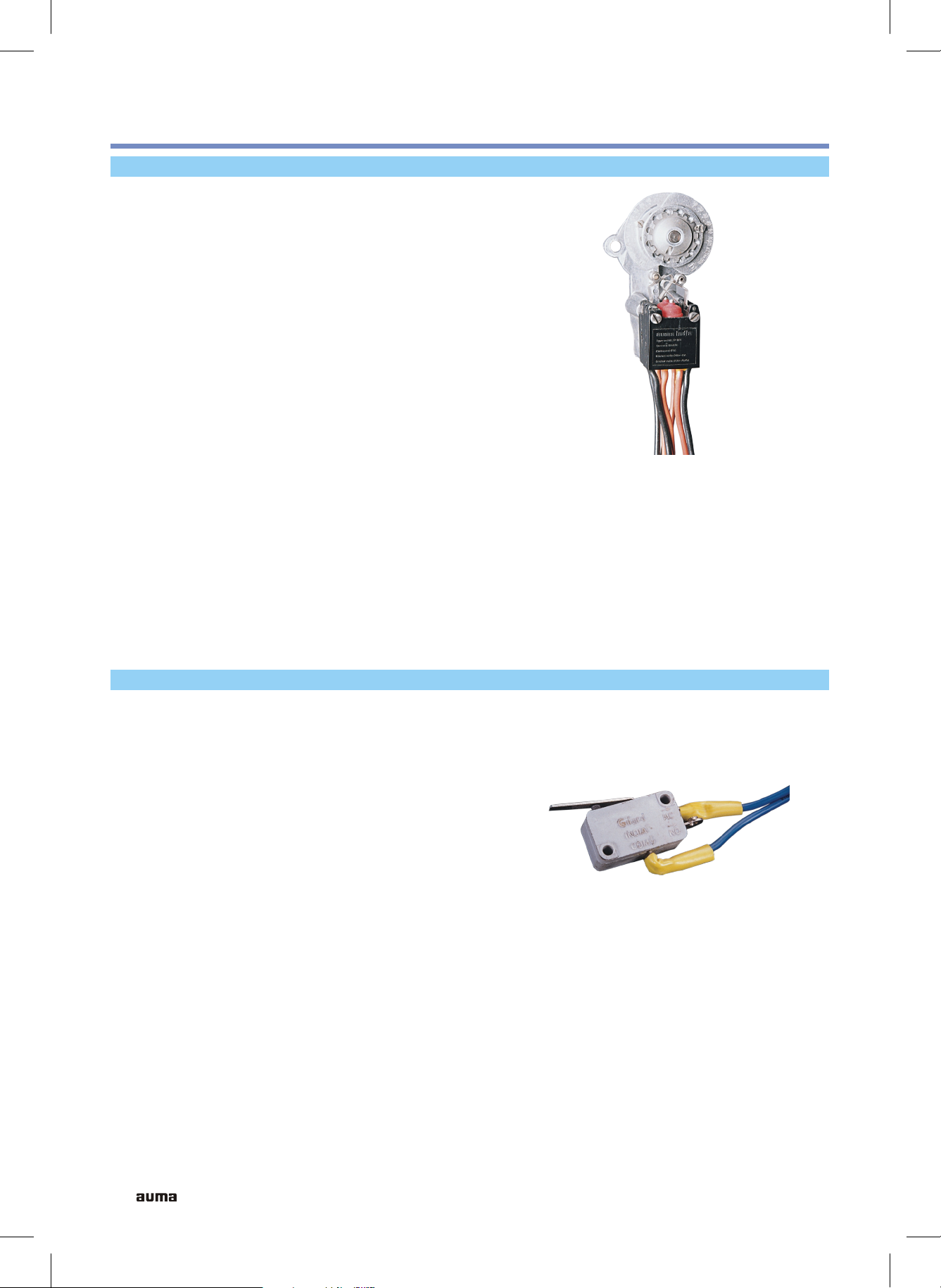
Micro Switches
Control Equipment
With the help of micro switches, mechanical
parameters such as travel & torque are
converted into electrical signals for actuator
control. There are four switches in the basic
version :
One limit switch each for the end
positions OPEN and CLOSE
One torque switch each for the
directions OPEN and CLOSE.
Single and Tandem Micro Switches
Limit and Torque Switches are available in
single or tandem versions.
Limit switches are tripped when an end position
is reached and torque switches are tripped when
the set tripping torque is exceeded.
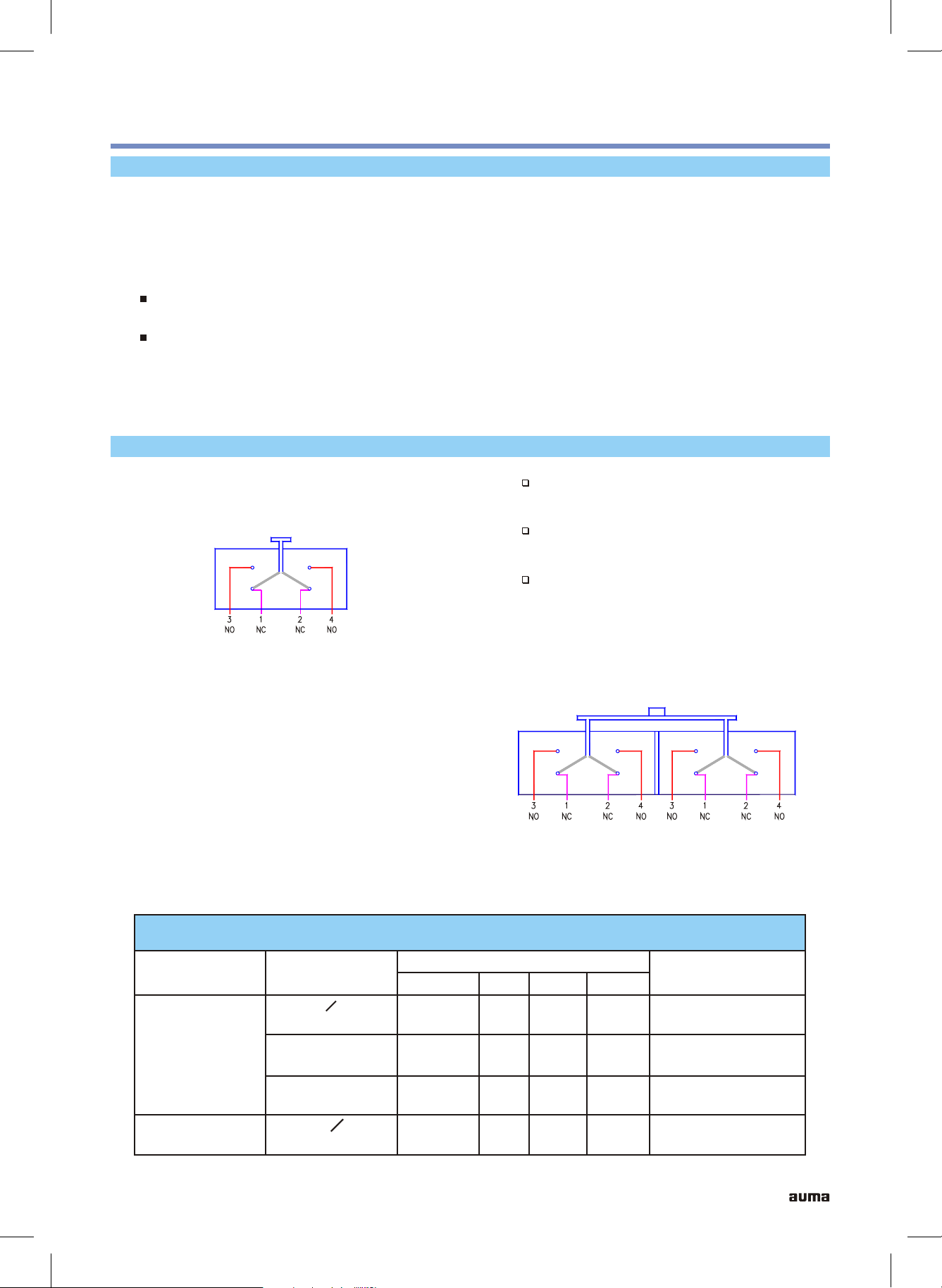
The micro switches are sealed to enclosure
protection class IP66, as per IS 13947. The micro
switches have double break change over
potential free contacts. The circuit is interrupted
simultaneously at two points. The basic versions
of the switch contacts are of silver. For low
current ratings, micro switches with gold plated
contacts are available.
Switching another circuit also with
different voltage & current
Safety function, to operate with single
switch
Multiplying the available contacts,
example for signalization.
Single Micro Switch
Limit or Torque Switches in tandem version
have additional switching contacts. These
contacts can be wired for following applications :
Micro Switch Ratings
Type of Switch
Limit and
Torque
Type of
Current
AC, cos O = 0.8
Inductive
DC inductive
30 V
DC resistive
Blinker
AC, cos O = 0.8
Inductive
For such applications, a relay is recommended
since there may be small differences in tripping
points of tandem switches.
Rating in Amp at
75 V
8
5
7
7
1
1
Tandem Micro Switch
125 V 250 V
6
0.2
0.5
5
0.1
0.25
4
Approx. Electrical
contact rating
500,000 cycles at
250 V AC, 5A
50,000 cycles at
250 V DC, 0.1A
50,000 cycles at
250 V DC, 0.25A
11
Page 12
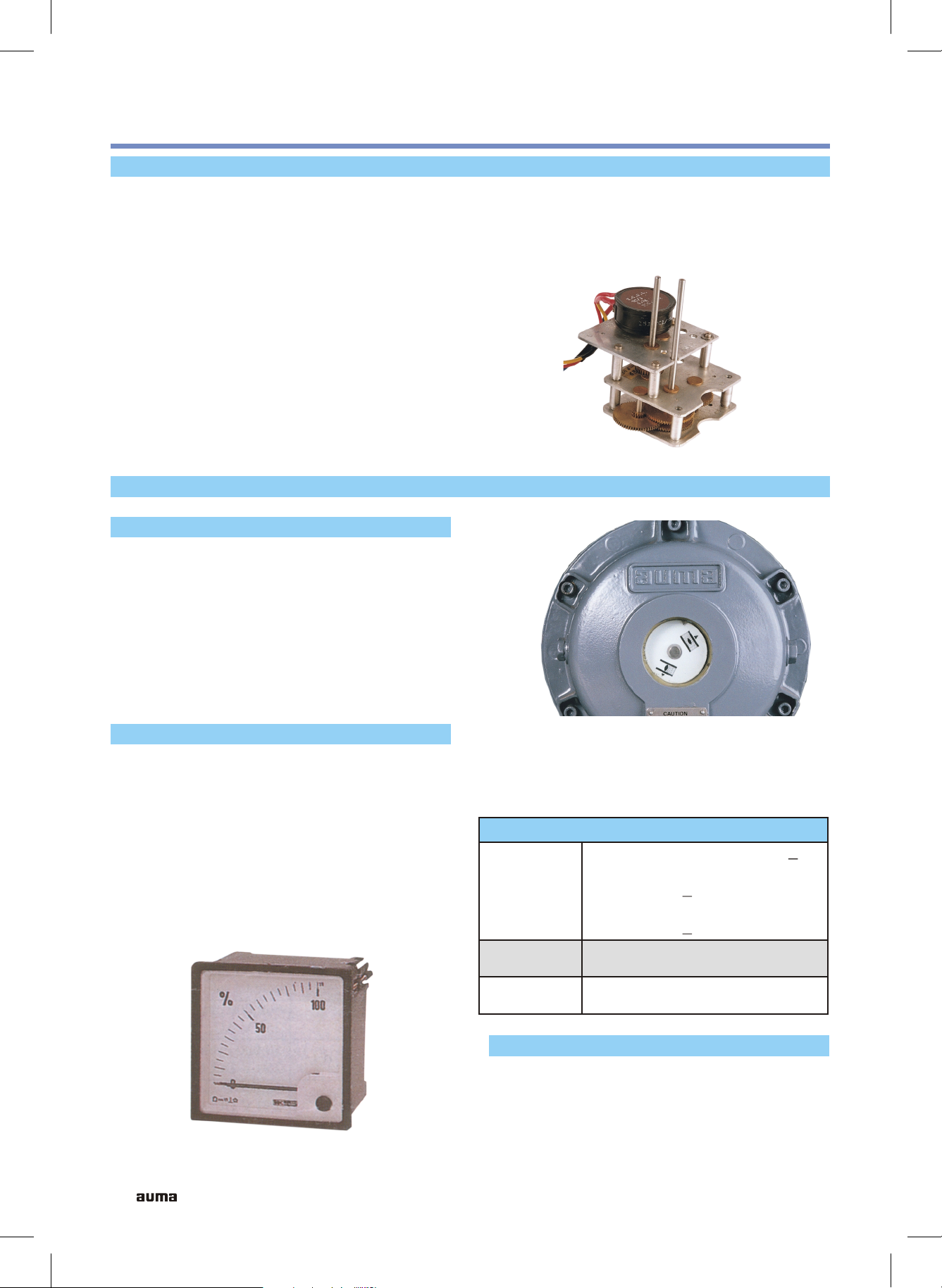
Control Equipment
Reduction Gear Unit
A reduction gear unit (RGU) in the actuator is
used for mechanical position indication,
remote position indication & for operation of
intermediate switches. The output shaft of the
actuator drives final output shaft of RGU
through a series of reduction gears and final
shaft turns by approximately 270 while
o
actuator output shaft performs full number of
turns as set on two train or four train counter
gear unit. The reduction gear ratio needed for
each particular case is fitted at works if the
ratio is known. For this purpose fixed RGU
is supplied. If the ratio needs to be altered
Position Indicators
Mechanical Position Indicator
The position of the valve is indicated
continuously by adjustable discs having
symbols for OPEN and CLOSE. The discs can
be seen through an indicator glass on switch
compartment cover. The open-close discs can
be set to coincide with limit switching. The
mechanical position indicator requires
reduction gear unit for operation.
at site, variable ratio RGU is available which
allows simple modification at site depending
upon number of turns of output shaft for full
stroke of valve.
Reduction Gear Unit (RGU)
Remote Position Indicator
The position of the valve can be transmitted as
a continuous signal for remote indication. A
potentiometer mounted on RGU is used for
this purpose. A power supply unit provides
necessary voltage to the potentiometer. The
potentiometer rotates through 270 for one full
o
stroke of valve & output signal from
potentiometer is proportional to valve travel.
Thus the actual position of the valve can be
Mechanical Position Indicator
read off continuously on position meter
calibrated & mounted on control panel.
Technical Data
Std: 220 ohms, 3W, Linearity + 3%
Optional : 100, 560, 1000 ohms,
Potentiometer
3W, Linearity + 3%
Precision : 200, 500, 1000 ohms,
1W, Linearity + 0.5%
Power
Supply Unit
Position
PS01, input 220V, 50Hz, output
24V DC
0 - 100% in various sizes
Meter
Digital Remote Position Indicator
Actual position display can be provided by
digital remote position indicator, which
displays open position in percentage.
12
Remote Position Indicator
Page 13

Intermediate Switches
With this limit switching, additional switching
points can be set for each direction of rotation.
The switching can be set between 25 and 75%
of valve travel in each direction. The switch
sub assembly consisting of 2 or 4 cam switches
is mounted on output shaft of RGU. Each
micro switch has 1 NO + 1 NC contact.
Manual Operation
For commissioning or in an emergency when
there is no power supply, actuator can be
operated by hand wheel. The manual drive is
engaged by means of a lever. When motor
starts running, the manual drive gets
disengaged immediately & hand wheel does
not rotate during power operation.
Control Equipment
Intermediate Switches
In manual operation, hammer blow can be
effected with hand wheel. The hammer blow
makes it possible to open a jammed or rarely
operated valve.
Top Bevel Gear Set
Manual effort on hand wheel can be further
reduced by using a side mounted hand wheel
instead of standard hand wheel. Reduction
ratios available are
SA3 / 6 / 12 / 15
SA25 / 30 / 50 / 60
SA 100
Instead of hand wheel, a chain pulley can be
provided for actuators mounted in inaccessible
zones.
Space Heater
2 : 1
3 : 1
4 : 1
Top Bevel Gear Set
Condensation in the actuator is possible due to
wide fluctuation of the ambient temperature.
The heater integrated in the control unit
prevents the water condensation. The heater is
rated for continuous duty. This may be
continuously energized or when the actuator
is not operating.
Technical Data
Volts, AC
Resistance
ohms
Rating
Watts
230
5K
10 20 10 20
230 110 110
2.7K 1.2K 0.6K
13
Page 14
Control Equipment
Motors
As a standard, Auma multi turn actuators are
equipped with 3 phase induction motors.
Auma motors are class F insulated and
withstand winding temperature upto 140 C.
o
The motors are used for short time duty (S2-15
min or S4-25% as per IS 12824) and provide
approximately three times rated torque for
short duration. The size of the motor is smaller
compared to continuous duty motor S1 of
same output power. This results in reduced
inertia of the rotor and therefore less
overshoot after switching off of motor. Auma
motors are designed for enclosure protection
class IP 68 when mounted on the actuator. All
motor cables are brought to terminal
compartment cover from inside of the actuator
thus avoiding terminal box.
Technical Data
Single Phase AC Motors
Auma actuators can be supplied with single
phase AC motor. The required capacitor is fitted
in the terminal compartment cover.
DC Motors
Auma actuators are also available with DC
motors. These motors operate on 24 V, 110 V or
220 V DC supply.
AC Motors with Other Voltages and
Frequency
Three phase induction motors are available in
wide range of operating voltages from 220 V to
560 V and operating frequency of 50 or 60 Hz.
3 ph AC Motor 1 ph AC Motor DC Motor
50/60 Hz : 220 V, 380 V
50/60 Hz :
400 V, 415 V
Voltages
440 V, 460 V
480 V, 500 V
550 V
Permissible Variation
in Voltage
+ 10%
Mounting C Type Flange, B14, IS 2223
Enclosure Protection IP 67 or IP 68 after mounting
Type of Cooling Surface Cooled
Insulation Class
F Class, IS 325 (max. temp. rise 140 C)
Starting Direct on line
Type of Duty S2-15 min. or S4-25 % IS 12824
Direction of Rotation Clockwise and anticlockwise
220 V - 240 V
110 V - 220 V
220 V
110 V
48 V
24 V
+ 10% + 10%
o
Motor Protection 3 thermo switches 2 thermo switches 4 thermo switches
14
Page 15

Motor Protection
Control Equipment
Motor winding may get overheated if the
actuator is run beyond rated duty or if the
rotor is stalled for considerably longer time or
if too high ambient temperature is
encountered. In order to protect the motor
against over heating, thermo switches are
embedded in the windings of three phase,
single phase AC motors and DC motors. When
integrated into the control circuits, they will
protect the motor against damage due to
excessive winding temperature.
The thermo switches interrupt the control
circuit as soon as winding temperature of
o
140 C is exceeded. After cooling down to a
temperature of approx. 110 C, the actuator can
o
be switched on once again. PTC thermistors
can also be provided for motor protection.
Output Speeds
With large range of available output speeds,
almost every required operating time can be
achieved with Auma actuators.
The actuator output speed is determined by
the motor speed, change gears and reduction
gear ratio of worm / worm wheel.
The output speeds are available from 4 - 180
rpm in geometric progression of 1: 1.4.
During trial run, if found necessary, the
output speed can be easily changed by
Technical Data
AC Voltage
250 V AC
Cos O = 1
250 V AC
Cos O = 0.6
Tripping Temp 140 C
Reset Temp 90 - 110 C
o
o
Switch Rating
2.5 A
1.6 A
Note : The motor protection device must be
integrated into the controls, otherwise warranty
for motor is not valid.
exchanging the change wheels and or motor at
site. The grease filled housing need not be
opened for this purpose. The torque switch
setting & limit switch setting remains the same.
For actuators with output drive A (Stem nut),
max. permissible stem velocity must be
observed:
-
for gate valves max. 500 mm/min
-
for globe valves max. 250 mm/min
For higher velocities it is recommended to use
spring loaded stem nut type AF (special design).
Self Locking
Auma multi turn actuators SA/SAR3 to
SA/SAR100 are self locking (see note below)
with exception of output speeds 125 & 180
rpm. Actuators with 125 & 180 rpm are having
double start worm drive. After torque switch is
tripped, the sliding worm may move back to
initial position by the action of torque
measuring springs. This allows torque switch
to be released. If control system provides
continuous signal, this results in hunting of
motor. This can be avoided by the use of
auxiliary relay.
Note on Self Locking :
Self-locking gearing does not ensure safe
stopping after an operation. If this is required,
separate locking arrangement must be provided.
15
Page 16

Actuators for Regulating Duty
Description of Regulating Duty
Auma actuators of type SAR are suitable for
Regulating duty / Modulating duty. SAR
actuator operates between two set bands in
closed loop and the motor is started, stopped
& reversed at short intervals to correct the
deviation from the set value. SAR actuators
differ from SA actuators in several respects :
- 4 pole motors are used to reduce overshoot
- Worm with high quality finish on flanks for
better efficiency
-
Disc springs on worm shaft are pre
compressed to reduce dead band when
reversing.
While selecting Auma actuators for regulating
duty applications, following points should be
noted :
Principle of Operation
Max. No. of starts-
1200 cycles / hour with motor power upto
0.55 kW & 600 cycles / hour with motor
power above 0.55 kW.
Output speed of actuator max. 45 rpm.
-
-
Torque for regulating duty should not exceed
50% of max. torque of actuator.
-
Max. torque of actuator can be used for
seating & unseating of the valve.
For reversing service, duration of impulse
should be minimum of 50 ms.
-
Electronic position transducer or precision
potentiometer should be used for remote
position indication.
-
The motor should be short time duty
class S4 - 25%.
The SAR actuator basically consists of
control units as explained in following
diagram.
16
SAR
MSAR
MUSAR
Regulating duty actuator
:
Sensor for actuator, i.e.
:
position transmitter at actuator
(potentiometer or inductive
LVDT)
Signal converter for SAR i.e.
:
Electronic position transducer
(RWG 1001/RWG 2002) or
inductive position transmitter
(IWG 1002/ IWG 1003).
CU01
V
M
MU
SE
W
XR
YR
:
Electronic positioner
:
Regulating valve
:
Sensor for regulating valve
:
Signal converter for sensor
:
Setting nominal value
:
Reference input
:
Input value at controller
:
Output value at electronic
positioner
Page 17

Description of Electronic Units
Actuators for Regulating Duty
Sensor for Actuator
A potentiometer is used as sensor for actuator.
Single turn wire wound potentiometer with
4.7 k ohms with linearity of + 0.5 % is available
for this purpose. It is available in single or
tandem version.
Electronic position transducer RWG 1001
This device is a signal converter for the
transformation of resistance value into
proportionate current signal. It can also be
placed in the actuator where the position
determined by the potentiometer is converted
into 4-20 mA current signal.
As position transmitter, preferably a
potentiometer of 4.7 k ohm should be used so
that the reference voltage source is not over
loaded. This device requires 24V DC power
supply regulated within + 15%. Auma power
supply unit PS01 is recommended for this
purpose. RWG 1001 is a 3 wire system and is
having linearity of 0.05 %.
Electronic position transducer RWG 2002
This is basically same as RWG 1001, however
with 2 wire system. The linearity is less than 1%.
Technical Data
Resistance 4.7 k ohms + 0.5 %
Power rating
Angle of rotation
Linearity
3 Watt at 40 C
oo
275 + 5
+ 0.5%
o
RWG 1001
Technical Data - RWG 1001
Configuration 3 Wire
Supply Voltage
Output Current
Input resistance
Displacement of zero
position, max.
Displacement of end
position, max.
Influence of supply
24V DC
min. 18, max. 33V
0-20 mA
(4-20 mA)
150 k ohms
+ 25%
from 50 to 100%
Max. 0.2%
voltage variation
Temp. drift
Linearity not considering
potentiometer
0.2% 10 C
0.05%
o
RWG 2002
Technical Data - RWG 2002
Configuration 2 Wire
Supply Voltage
Output Current
Input resistance
Displacement of zero
24V DC
min. 18, max. 33V
4-20 mA
150 k ohms
+ 25%
position, max.
Displacement of end
position, max.
Influence of supply
from 60 to 100%
Max. 0.15%
voltage variation
Linearity not considering
potentiometer
< 1%
17
Page 18

Actuators for Regulating Duty
Description of Electronic Units
Dual Output Position Transmitter RWG 2002 DG :
It is a signal converter device for the
transformation of resistance value into
proportionate galvanically isolated two current
outputs. This device requires 24 V DC power
supply regulated within + 10%. Auma power
supply unit PS01 is recommended for
this purpose.
Inductive Position Transmitter IWG 1002
When using Auma actuators for regulating duty
with demand of high accuracy, an inductive
position transmitter can be fitted to give precise
read out of position.
Technical Data - RWG 2002 DG
Supply Voltage
Output 1 (Isolated)
Output 2 (Isolated)
Current Drawn
Adjustability of Span
Adjustability of Zero
Change in Output due to
Input Supply Variation
24V DC
+ 10% regulated
0/4-20 mA
0/4-20 mA
100 mA
+ 50%
+ 25%
< 0.2%
Operating Temperature
Range
Linearity Error for both
Outputs
- 20 C to + 80 C
< 1%
oo
The output signal is used as feed back to
electronic positioner or for position indicator.
The system consists of two parts, a linear
variable differential transformer (LVDT) and
an electronic unit. The smallest change of
magnetic core in the measuring coil is
transformed into proportional signal. The
transmitter has no moving contacts. This device
requires 24 V DC power supply regulated
within + 15%. Auma power supply
unit PS01 is recommended for this purpose.
The linearity of the unit is less than 0.3%.
IWG 1002
Technical Data - IWG 1002
Configuration
Supply Voltage
Output Current
Resistance max.
Displacement of zero
position, max.
Displacement of end
position, max.
Temp. drift
Linearity (not
considering LVDT)
2 Wire
24V DC
+ 15% regulated
4-20 mA
600 ohms
+ 25%
60 to 100%
0.4% / 10 C
o
< 0.3%
18
Page 19

Description of Electronic Units
Inductive position transmitter IWG 1003
Actuators for Regulating Duty
IWG 1003 is similar to IWG 1002 however with
3 wire system.
IWG 1003
Electronic Positioner CU01
The electronic positioner CU01 is designed as a
three level positioner for regulating of actuator.
By comparing two input signals (reference
signal W & regulating signal X), the positioner
determines the difference. In case this exceeds a
certain value, the actuator is switched on by
relays. The direction of rotation (opening or
Technical Data - IWG 1003
Configuration
Supply Voltage
Output Current
Resistance max.
Displacement of zero
position, max.
Displacement of end
position, max.
Temp. drift
3 Wire
24V DC
+ 15% regulated
0 / 4-20 mA
600 ohms
+ 25%
60 to 100%
0.4% / 10 C
o
Linearity (not
considering LVDT)
< 0.3%
closing) depends upon the plus or minus sign of
the deviation. Thus the regulating signal
generated by potentiometer or LVDT changes &
when the regulating signal & reference signal
become equal, the actuator stops as long as no
new correction is required.
CU 01
Technical Data
Input WE1 0-20 mA (4-20 mA)
XE2
0-20 mA (4-20 mA)
or 0-Uref
Time delay
Adjustment of zero
0.5-15 secs.
0 - 20%
point
Adjustment of end
position
Sensitivity (dead
60 to 100%
1% - 2.5%
band)
Relay output (max.
resistive load
230V, 10A
19
Page 20

Actuators for Regulating Duty
Description of Electronic Units
Signal Isolator
Auma signal isolators are available in various
versions :
Power supply conditions :
230V AC, 110V AC or 24V DC
Various input signals :
4-20 mA or 1-5 V
Signal Isolator
Power supply unit PS01
Various output signals :
4-20 mA single or dual or 4-20 mA & 1-5V
Isolation is provided between input and output
and between two outputs.
Technical Data
230V AC + 15%
Power Supply
Input
Output
Accuracy
Zero & span
adjustment
110V AC + 15%
24V DC + 1V
4-20 mA
1-5V
4-20 mA single
4-20 mA dual
4-20 mA & 1-5 V
+ 0.1% of output span
+ 2% min. at zero
+ 10% min. at span
This unit gives 24V DC power supply for
regulating system (example : for CU01) & for
remote position indication (example : by a
voltmeter suitably calibrated). There are two
versions available:
Version I : For regulating application with
CU01 :
The output voltage Uo & Uc require no trimming
potentiometer. The voltage Uc is diverted from
voltage Uo, thus Uc can serve as common
reference potential for whole regulating system.
This version is suitable for IWG 1003 or
RWG 1001.
Supply voltage to PS01 is 220V or 110V +
15%, 50 Hz
The maximum output voltage is
Uo = 24V + 1 V DC
Uc = 5.5V + 0.5V DC
Version II : For remote position indication with
potentiometer 220 ohms as position transmitter :
In this two additional potentiometers P1 and P2
are provided for positions zero and maximum.
Version II
Technical Data - PS01
Supply voltage and
frequency
Power drawn
220V or 115V (+ 15%)
50 Hz or 60 Hz
9 VA
20
Version I
Output voltage
max.
Mounting
24V +1V DC
Snap on type for DIN
rail 46277
Page 21

Auma Norm Actuators
This actuator offers a complete actuator type SA
with electric motor, torque switch for open close direction, limit switches for both end
positions & blinker switch for running
indication. The required reversing contactor
should be installed separately & wired to the
motor. For signalization of the switching and to
trip the contactors over micro switches, control
wires are required from actuator terminal
compartment cover to reversing contactor
installed separately.
Auma Integral Starter Actuators
Actuator Types
Auma Norm
The purpose of offering Integral motor controls
for the actuator is to enable the customer to save
high installation costs for external controls.
Actuators with integral controls include control
& switching elements and are supplied
ready for use.
All electrical components such as limit, torque,
thermo switches, all monitoring elements &
position transmitter are integrated into modern
controls.This results in following simplification.
- No extensive wiring in the external control
cabinet
-
Several actuators can be connected to common
supply cable using isolating switch for each
actuator.
-
Actuator signals are processed in the controls,
only feed back to process control system is
necessary.
-
Integral starter housing can be easily
exchanged due to multi pin plug connector
between actuator & integral starter unit.
-
Actuator can be operated from Local or
Remote position by means of selector switch
on the integral starter unit.
Auma Integral Starter
21
Page 22

Actuator Types
Control Versions of Integral Starter Units
Auma Compact
This is a simpler version of Integral Starter Unit
with selector switch & push buttons. The
selector switch has 3 positions :
LOCAL :
The actuator can be operated locally i.e. at the
actuator by push buttons OPEN-OFF-CLOSE.
The running direction is indicated by LEDs.
REMOTE :
The actuator can be operated from remote
control station. The running direction is
indicated by LEDs on the actuator.
OFF :
The actuator cannot be operated with local
controls or from remote.
The selector switch can be locked in any position
with pad lock. The compact unit is completely
wired with reversing contactors and no
additional control box is required.
Auma compact is available as Norm or
Regulating duty actuator. Depending upon Norm
or Regulating duty, following features /
optionals are available :
Reversing contactors
Selector switch
Push buttons & indicating lamps
Thermal overload relay
Power supply unit PS01 for 24 V DC output
Electronic positioner CU01
Electronic position transducer RWG / IWG
Phase discriminator
Signal isolator
DC relay for remote operation
Remote annunciation relay for supply
indication
Multi pin connector can be provided between
actuator and compact and between compact &
terminals for customer connections.
22
Auma Compact
Page 23

Control Versions of Integral Starter Units
Auma e-pac
Actuator Types
The electronic version of Auma India Integral
Starter e-pac incorporates sophisticated
electronic controls with field programming
feature. E-pac is modular in construction and
consists of Power Supply Module, Relay
Module & Programmable Control Module.
Power Supply Module consists of
24 V DC, 150 mA source
Reversing contactors electrically and
mechanically interlocked
Selector switch LOCAL-OFF-REMOTE,
lockable & potential free contacts for localoff & remote
Push buttons OPEN-STOP-CLOSE for
local controls
Single phase supply for space heater 10W
Relay Module consists of
Monitor relay for collective fault
signals (Thermo switch trip, torque switch
trip in mid travel) with potential free contacts
Local status annunciation (Green) & fault
annunciation (Red) by LEDs
Programmable Control Logic Module consists
of
Inching & Non-inching in local mode by dip
switches
Inching & Non-inching in remote mode by dip
switches
Limit switch seating or Torque seating by dip
switches
Wide varieties of versions of e-pac & optional
features make the actuator controls adaptable to
any field situation. Versions & optionals
available are :
Emergency shut down (ESD)
2 wire make-break
Timer board to run the actuator in ON-OFF
steps
Open-Close inhibit
Negative switching
Remote control & local stop
Electronic positioner for regulating duty, with
or without isolator
Single phase protection
Automatic phase correction
Remote annunciation relays
Thermal overload relay
Positioner with PID features
Wall mountable e-pac
For detailed literature, refer separate catalogue.
Auma e-pac
23
Page 24

Interface
Valve Attachment
Valve attachment is according to ISO 5210 or DIN 3210
Flange Sizes
Actuator size
SA/SAR
Max. Torque
Nm
ISO 5210
DIN 3210
3
6
30 60 120 150 250 300 500 600 1000
F10
F10 F10 F10 F14 F14 F14 F14 F16
G0 G0 G0 G0 G3
Output Drives
Various output drive types according to ISO
5210 / DIN 3210 are available in order to
adapt the actuators to different types of valves.
Special sizes can be supplied on request.
Output Drive Type A
Stem nut :
The output drive has stem nut for rising or non
rotating valve stem. The mounting flange
together with stem nut and thrust bearings form
one assembly which is suitable for accepting
thrust loads.
12
15 25 30 50 60 100
G
1
1
1
G
G
2
2
1
G
2
2
Output Drive Type D
Stub Shaft :
The shaft with key engages with bore and
keyway of mating part.
Output Drive Type E
Bore with Keyway :
This type is mainly used for connecting to a gear
box, example Auma Gear Box type GS
(worm / worm wheel) or GK (Bevel gear box).
Output Drive Type B
Plug Sleeve :
Plug sleeve has bore and keyway and is designed
for transmission of torque.
Output Drive Type C
Dog Coupling :
This is similar to type B, however with dog
coupling for torque transmission.
24
Linear Thrust Unit (LTU)
With the linear thrust unit, the rotary movement
of the actuator output shaft is converted into an
axial movement. Thus the multiturn actuator
becomes linear actuator. Different stroke lengths
can be provided.
Technical Data
Linear Thrust
Unit
LTU 6
LTU 12
LTU 25
LTU 50
Tr.
Thread
24 x 5
32 x 6
40 x 7
50 x 8
Max.
thrust
kN
20
35
63
100
Stroke
length
mm
50 & 100
60 & 120
80 & 160
80 & 160
Page 25

Electrical Connection
Terminals
Interface
Screw type terminals are used for electrical
connection as standard. Stud type terminals can
be provided for power connections. Terminals
are DIN rail mountable and are available as
single or double decker versions also.
Plug socket connector
The actuators can also be equipped with plug
socket connectors in two versions.
Electrical Connection for Integral Starter Versions
Between actuator and compact or e-pac :
64 pin connector with 3+1 pins for power
connection or 50 pin circular connector with
6+1 pins for power connection. This simplifies
trouble shooting at site.
From compact or e-pac to customer connections:
Screw type terminals or 64 pin connector with
3+1 pins for power connection or 50 pin circular
connector with 6+1 pins for power connection.
Version I :
32 x 2 = 64 pins for control
3 + 1 = 4 pins for power
Version II :
50 pin circular connector for control
6 + 1 = 7 pins for power
Technical Data
Power
Screw type terminals
Terminals max.
Voltage max.
Current max.
Type of Connection
Cross section max.
Plug socket connector 32 x 2 & 3 + 1
No. of contacts
Voltage max.
Current max.
Type of connections
for customer use
Cross sec. max.
Plug socket connector, circular
No. of contacts
Voltage max.
Current max.
Type of connections
for customer use
3
750 V
34 A -
Scr or stud
4 sq mm
3
750 V
25 A
Screws
6 sq mm
6
(3 used)
750 V
25 A
Screws
Earth
1
-
Scr or
stud
4 sq mm
1
-
-
Screws
6 sq mm
1
-
-
Screws
Screw type terminals
Controls
64
500 V
25 A
Scr
2.5 sq mm
64
Multi-pin Connector
500 V
16 A
Screws
2.5 sq mm
50
250 V
16 A
Circular Connector
Screws
Cross sec. max.
6 sq mm
6 sq mm
2.5 sq mm
25
Page 26

Interface
Threads for Cable Glands
As standard, Auma actuators are supplied with
2 cable glands with British Conduit threads
1
''
1/
1 BSC. The cable glands are directly tightened
4
on the threads provided in cable entry cover. At
the time of despatch, the cable entry opening in
the cable gland is sealed with aluminium shim
& neoprene rubber sheet to prevent ingress of
dust & water.
Stem Protection Tube
3
''
Additional cable glands of sizes , 1'' can be
3/4''
4
provided. For additional protection under
extreme conditions for weather proof & water
proof applications, double compression cable
glands in various sizes can be supplied. NTP &
PG threads can also be provided.
To protect rising valve stem, a protection tube
can be fitted to the hand wheel hub. Internal
threads are provided in the hand wheel hub
Actuator - Gear box Combinations
Combination with Worm Gear boxes
In combination with worm gear box of type
GS40.2 to GS500, a multiturn actuator is
converted into part turn actuator usually for 90
o
movement. This is an ideal solution for large part
turn valves with high torque requirements. The
torque range goes upto 250000 Nm.
Combination with Bevel Gear boxes
By combining multiturn actuators with Bevel
gear boxes GK10.1 to GK35.1, the torque speed
ranges are considerably extended. Output
torques upto 8000 Nm and thrust load upto
820 KN are possible.
as a standard. If protection tube is not required,
the bore of the hand wheel hub is closed with lid.
Combination with Lever Gear boxes
Louvers, dampers or valves which are operated
via lever arrangement require lever gear boxes.
For such application multiturn actuator is
combined with lever operated Gear box type
GF40 to GF315. The torque range goes
upto 63000 Nm.
26
GEAR OPERATORS
Page 27

Enclosure Protection
Service Conditions
Auma actuators conform to enclosure protection
IP67 as per IS 13947 (Part I) : 1993, Appendix C.
Auma actuators are also available with improved
enclosure protection IP68. The definition of
IP67 & IP68 as per standard is as follows :
IP : Ingress Protection
First numeral 6 : Dust tight, prevents ingress
of dust.
Second numeral 7 : Protected against the effects
of immersion. Test is made by completely
immersing the equipment in water so that :
Surface of water is atleast 150 mm above
highest point of equipment.
Ambient Temperature
Type
SA
SAR
Actuator Type
Standard
Multi-turn actuator
Multi-turn
Actuator for
Temp.
Range
-20 to +80 C
-20 to +60 C
o
o
Regulating Duty
SAEx
SAREx
SACEx
SARCEx
Explosion Proof
actuators, standard
compact &
regulating duty
-20 to +40 C
o
The lowest point of equipment is atleast 1 m
below the surface of water
Duration of test is 30 min.
Under above conditions, ingress of water in
harmful quantity shall not be possible.
Second numeral 8 : Test conditions as above,
however no ingress of water is permitted.
Life Time
Auma multi-turn actuators meet the following
requirements of operating cycles at 30 turns per
stroke of close - open - close.
SA3 to SA100
SAR6 to SAR100
15000 Cycles
15000 Cycles
Painting
Type of paint
Standard colour
Primer thickness
Paint thickness
Epoxy
DA grey IS 5
40 microns min.
75 microns min.
Any other type & colour of paint can be provided
on request.
27
Page 28

Service Conditions
Explosion Proof / Flame Proof Actuators
For installation of actuators in potentially
hazardous or explosive areas, special protective
measures are required. These are specified in
Indian Standard IS 2148-1981 ''Specifications
for Flame Proof Enclosures of Electrical
Apparatus''. Auma India actuators developed for
this purpose are suitable for group II gases and in
application other than coal mines. The
enclosures of explosion proof / flame proof
actuators are designed in consideration of
clauses specified in IS 2148-1981 & the
actuators have been tested and certified by
CMRI, Dhanbad.
Necessary approvals from statutory authorities
have been obtained.
Actuator Models
Actual Type Model
Explosion Proof
Norm
Open-Close Duty
Explosion Proof
Norm
Regulating Duty
Explosion Proof
Compact
Open-Close Duty
Explosion Proof
Compact
Regulating Duty
SAEx3/6/12/15
SAEx25/30/50/60
SAEx100
SAREx6/12/15
SAREx25/30/50/60
SAREx100
SACEx3/6/12/15
SACEx25/30/50/60
SACEx100
SARCEx6/12/15
SARCEx25/30/50/60
SARCEx100
For details please refer separate catalogue.
-
SAEx3
SAEx100
SAREx6
- SAREx100
SACEx3
- SACEx100
SARCEx6
SARCEx100
-
28
EN ISO 9001
EN ISO 9001
Certificate : 041005262
Certificate : 041005262
Page 29

Mounting Position Functional Tests
General
Auma actuators also with integral controls can
be operated without restriction in any mounting
position.
Test Certificates
Auma actuators and critical components of
actuators have been tested & guaranteed for
performance. Some of the Type test certificates
available are listed.
Endurance Test as per GDCD Standard
Damp Heat Cycle Test as per IS 9000
Vibration Test as per IS 12075
Noise Test as per IS 12065
Enclosure Protection Test as per IS 13947
Tests on Micro Switches
Motor Performance Tests
After assembly, all actuators are thoroughly
tested and torque switches are calibrated. Final
inspection record is provided to the customer.
29
Page 30

Technical Data
Open-Close duty
Tripping Torque
both directions
Min.Nm
20 26 25 250
20 26 40 250
1)
Max.Nm
30
60
55
30 38 60 250
120
110
50 38 60 250
150
60 52 120 360
250
Actuator Type
Type
SA
3
SA
3
SA
3
SA
3
SA
3
SA
3
SA
3
SA
3
SA
3
SA
6
SA
6
SA
6
SA
6
SA
6
SA
6
SA
6
SA
6
SA
6
SA
6
SA
6
SA
6
SA
12
SA
12
SA
12
SA
12
SA
12
SA
12
SA
12
SA
12
SA
12
SA
12
SA
12
SA
12
SA
15
SA
15
SA
15
SA
15
SA
15
SA
15
SA
15
SA
15
SA
15
SA
25
SA
25
SA
25
SA
25
SA
25
SA
25
SA
25
SA
25
SA
25
SA
25
SA
25
SA
25
Auma India
Output Speed
1/min
.....
.....
.....
.....
.....
.....
.....
.....
.....
.....
.....
.....
.....
.....
.....
.....
.....
.....
.....
.....
.....
.....
.....
.....
.....
.....
.....
.....
.....
.....
.....
.....
.....
.....
.....
.....
.....
.....
.....
.....
.....
.....
.....
.....
.....
.....
.....
.....
.....
.....
.....
.....
.....
.....
2)
11
16
22
32
45
63
90
125
180
4
5.6
8
11
16
22
32
45
63
90
125
180
4
5.6
8
11
16
22
32
45
63
90
125
180
4
5.6
8
11
16
22
32
45
63
4
5.6
8
11
16
22
32
45
63
90
125
180
Valve
Mounting
Flange
Standard
DIN:3210
(Special
ISO:5210)
3)
3)
3)
3)
3)
3)
Stem dia.
Output drive
Type-A
Max. mm Max. kN Min. / Max.
Permissible
Thrust for
Type-A
G0
(F10)
G0
(F10)
G0
(F10)
G0
(F10)
1
G
2
(F14)
Revolutions
for
Full stroke
1-480
or
1-4800
1-480
or
1-4800
1-480
or
1-4800
1-480
or
1-4800
1-480
or
1-4800
SA3-SA100
Hand
wheel
Dia.
Std.
Hand wheel
Ratio
Std. Std.
1:1 2:1
1:1 2:1
1:1 2:1
1:1 2:1
1:1
With bevel
gear set
3:1
Weight
Auma India Norm
With bevel
gear set
Kgs. Kgs.
39 45
39 45
39 45
39 45
72
88
30
220
1) Infinitely adjustable 3) Non self locking
2) At 50 Hz
We reserve the right to alter data according to improvements made. Previous data sheets become invalid with the issue of this data sheet.
3)
3)
Page 31

Technical Data
Open-Close duty
Max.
Nm.
300
1)
Tripping Torque
both directions
Min.
Nm.
100 52 120 360
264
100 52
500
450
100
600
540
1000
Actuator Type
Type
SA
30
SA
30
SA
30
SA
30
SA
30
SA
30
SA
30
SA
30
SA
30
SA
30
SA
30
SA
30
SA
50
SA
50
SA
50
SA
50
SA
50
SA
50
SA
50
SA
50
SA
50
SA
50
SA
50
SA
50
SA
60
SA
60
SA
60
SA
60
SA
60
SA
60
SA
60
SA
60
SA
60
SA
60
SA
60
SA
60
SA
100
SA
100
SA
100
SA
100
SA
100
SA
100
SA
100
SA
100
SA
100
SA
100
SA
100
SA
100
Auma India
Output Speed
1/min
.....
.....
.....
.....
.....
.....
.....
.....
.....
.....
.....
.....
.....
.....
.....
.....
.....
.....
.....
.....
.....
.....
.....
.....
.....
.....
.....
.....
.....
.....
.....
.....
.....
.....
.....
.....
.....
.....
.....
.....
.....
.....
.....
.....
.....
.....
.....
.....
2)
900
4
5.6
8
11
16
22
32
45
63
90
125
180
4
5.6
8
11
16
22
32
45
63
90
125
180
4
5.6
8
11
16
22
32
45
63
90
125
180
4
5.6
8
11
16
22
32
45
63
90
125
180
3)
3)
3)
3)
3)
3)
3)
3)
Valve
Mounting
Flange
Standard
DIN:3210
(Special
ISO:5210)
1
G
2
(F14)
1
G
2
(F14)
1
G
2
(F14)
G3
(F16)
Stem dia.
Output drive
Type-A
52
65
Permissible
Thrust for
Type-A
Max.
kN
160
160
190
Revolutions
for
Full stroke
Min. / Max.
1-480
or
1-4800
1-480
or
1-4800
1-480
or
1-4800
1-480
or
1-4800
SA3-SA100
Hand
wheel
Dia.
Std.
640
640
800
Hand wheel
Ratio
Std. Std.
1:1
1:1
1:1
1:1
With bevel
gear set
3:1
3:1
3:1
4:1
Weight
Auma India Norm
With bevel
gear set
Kgs.
107
72
75
75
Kgs.
88
92
92
128200
Enclosure : IP67 - IS:13947
Actuators are rated for short time duty S -15min, based on 40 C ambient temperature. The nominal current
2
o
is based on an average load of approximately 35% of max. torque. The max. torque can be utilised for a short
time (e.g. to seat or unseat a valve) and the current can rise to max. value. Refer corresponding column for
current at max. torque in Electrical Data.
1) Infinitely adjustable 2) At 50 Hz 3) Non self locking
We reserve the right to alter data according to improvements made. Previous data sheets become invalid with the issue of this data sheet.
31
Page 32

Torque
Max.
Nm
30
60
55
120
110
150
250
Auma India
Actuator Type
Type
SA
3
SA
3
SA
3
SA
3
SA
3
SA
3
SA
3
SA
3
SA
3
SA
6
SA
6
SA
6
SA
6
SA
6
SA
6
SA
6
SA
6
SA
6
SA
6
SA
6
SA
6
SA
12
SA
12
SA
12
SA
12
SA
12
SA
12
SA
12
SA
12
SA
12
SA
12
SA
12
SA
12
SA
15
SA
15
SA
15
SA
15
SA
15
SA
15
SA
15
SA
15
SA
15
SA
25
SA
25
SA
25
SA
25
SA
25
SA
25
SA
25
SA
25
SA
25
SA
25
SA
25
SA
25
Output Speed
at 50 Hz
1/min
.....
11
.....
16
.....
22
.....
32
.....
45
.....
63
.....
90
.....
125
.....
180
.....
4
.....
5.6
.....
8
.....
11
.....
16
.....
22
.....
32
.....
45
.....
63
.....
90
.....
125
.....
180
.....
4
.....
5.6
.....
8
.....
11
.....
16
.....
22
.....
32
.....
45
.....
63
.....
90
.....
125
.....
180
.....
4
.....
5.6
.....
8
.....
11
.....
16
.....
22
.....
32
.....
45
.....
63
.....
4
.....
5.6
.....
8
.....
11
.....
16
.....
22
.....
32
.....
45
.....
63
.....
90
.....
125
.....
180
Electrical Data
Open-Close duty
Three phase Squirrel cage AC Motor 415V, 50 Hz
Nominal
Output
KW
0.06
0.06
0.06
0.12
0.18
0.18
0.37
0.37
0.37
0.06
0.06
0.06
0.12
0.12
0.12
0.18
0.37
0.37
0.55
0.55
0.55
0.06
0.12
0.12
0.12
0.25
0.25
0.37
0.55
1.1
1.1
1.1
1.1
0.06
0.12
0.12
0.25
0.25
0.37
0.55
1.1
1.1
0.12
0.25
0.55
0.55
0.55
0.55
1.1
1.1
2.2
2.2
2.2
2.2
Speed
1/min
1400
1400
1400
1400
2800
2800
2800
2800
2800
1400
1400
1400
1400
1400
1400
2800
2800
2800
2800
2800
2800
1400
1400
1400
1400
1400
1400
2800
2800
2800
2800
2800
2800
1400
1400
1400
1400
1400
2800
2800
2800
2800
1400
1400
1400
1400
1400
1400
2800
2800
2800
2800
2800
2800
Size
71
71
71
71
71
71
71
71
71
71
71
71
71
71
71
71
71
71
71
71
71
71
71
71
71
71
71
71
71
71
71
71
71
71
71
71
71
71
71
71
71
71
71
71
71
71
71
71
71
71
90
90
90
90
Nominal
Current
A
0.3
0.3
0.3
0.5
0.6
0.6
1.0
1.0
1.0
0.3
0.3
0.3
0.5
0.5
0.5
0.6
1.0
1.0
1.8
1.8
1.8
0.3
0.5
0.5
0.5
1.4
1.4
1.0
1.8
2.9
2.9
2.9
2.9
0.3
0.5
0.5
1.4
1.4
1.0
1.8
2.9
2.9
0.5
1.4
2.8
2.8
2.8
2.8
2.9
2.9
4.6
4.6
4.6
4.6
Current at
Max. Torque
A
1)
0.30
0.38
0.50
0.62
0.84
1.16
1.62
1.40
2.05
0.25
0.30
0.38
0.45
0.62
0.90
1.18
1.62
2.34
3.08
2.45
3.52
0.38
0.46
0.62
0.90
1.45
1.80
2.42
3.08
4.58
6.50
5.10
7.50
0.45
0.55
0.83
1.36
1.66
2.00
2.75
4.26
5.67
0.65
1.29
1.64
1.92
2.60
3.58
4.75
6.58
8.44
12.5
8.95
13.6
SA3-SA100
Starting
Current
A
1.2
1.2
1.2
2.3
3.3
3.3
5.5
5.5
5.5
1.2
1.2
1.2
2.3
2.3
2.3
3.3
5.5
5.5
9.0
9.0
9.0
1.2
2.3
2.3
2.3
4.6
4.6
5.5
9.0
16.0
16.0
16.0
16.0
1.2
2.3
2.3
4.6
4.6
5.5
9.0
16.0
16.0
2.3
4.6
12.0
12.0
12.0
12.0
16.0
16.0
40.0
40.0
40.0
40.0
Power
Factor
Cos o
0.6
0.6
0.6
0.6
0.7
0.7
0.76
0.76
0.76
0.6
0.6
0.6
0.6
0.6
0.6
0.7
0.76
0.76
0.62
0.62
0.62
0.6
0.6
0.6
0.6
0.5
0.5
0.76
0.62
0.72
0.72
0.72
0.72
0.6
0.6
0.6
0.5
0.5
0.76
0.62
0.72
0.72
0.6
0.5
0.51
0.51
0.51
0.51
0.72
0.72
0.83
0.83
0.83
0.83
Full load
Efficiency
(%)
46
46
46
55
60
60
68
68
68
46
46
46
55
55
55
60
68
68
70
70
70
46
55
55
55
50
50
68
70
72
72
72
72
46
55
55
50
50
68
70
72
72
55
50
60
60
60
60
72
72
80
80
80
80
32
220
1) Current at max. torque. We recommend to select switch gear and cables suitable for those values.
We reserve the right to alter data according to improvements made. Previous data sheets become invalid with the issue of this data sheet.
Page 33

Torque
Max.
Nm
300
264
500
450
600
540
1000
Actuator Type
Type
SA
30
SA
30
SA
30
SA
30
SA
30
SA
30
SA
30
SA
30
SA
30
SA
30
SA
30
SA
30
SA
50
SA
50
SA
50
SA
50
SA
50
SA
50
SA
50
SA
50
SA
50
SA
50
SA
50
SA
50
SA
60
SA
60
SA
60
SA
60
SA
60
SA
60
SA
60
SA
60
SA
60
SA
60
SA
60
SA
60
SA
100
SA
100
SA
100
SA
100
SA
100
SA
100
SA
100
SA
100
SA
100
SA
100
SA
100
SA
100
Auma India
Output Speed
at 50 Hz
.....
.....
.....
.....
.....
.....
.....
.....
.....
.....
.....
.....
.....
.....
.....
.....
.....
.....
.....
.....
.....
.....
.....
.....
.....
.....
.....
.....
.....
.....
.....
.....
.....
.....
.....
.....
.....
.....
.....
.....
.....
.....
.....
.....
.....
.....
.....
.....
1/min
4
5.6
8
11
16
22
32
45
63
90
125
180
4
5.6
8
11
16
22
32
45
63
90
125
180
4
5.6
8
11
16
22
32
45
63
90
125
180
4
5.6
8
11
16
22
32
45
63
90
125
180
Electrical Data
Open-Close duty
Three phase Squirrel cage AC Motor 415V, 50 Hz
Nominal
Output
KW
0.12
0.25
0.55
0.55
0.55
1.1
1.1
1.25
2.2
2.5
2.5
4.0
0.25
0.55
0.55
0.55
1.1
1.1
2.2
2.2
4.0
4.0
5.0
5.0
0.25
0.55
0.55
0.55
1.1
2.2
2.2
4.0
4.0
5.0
5.0
5.0
0.55
0.55
0.75
1.1
2.2
2.2
4.0
4.0
7.5
7.5
7.5
7.5
Speed
1/min
1400
1400
1400
1400
1400
1400
2800
2800
2800
2800
2800
2800
1400
1400
1400
1400
1400
1400
2800
2800
2800
2800
2800
2800
1400
1400
1400
1400
1400
1400
2800
2800
2800
2800
2800
2800
1400
1400
1400
1400
1400
1400
2800
2800
2800
2800
2800
2800
Size
71
71
71
71
71
90
71
90
90
90
90
90
71
71
71
71
90
90
90
90
90
90
112
112
71
71
71
71
90
90
90
90
90
112
112
112
71
71
90
90
90
90
90
90
112
112
112
112
Nominal
Current
A
0.5
1.4
2.8
2.8
2.8
3.7
2.9
2.7
4.6
5.3
5.3
10.2
1.4
2.8
2.8
2.8
3.7
3.7
4.6
4.6
10.2
10.2
9.9
9.9
1.4
2.8
2.8
2.8
3.7
6.9
4.6
10.2
10.2
9.9
9.9
9.9
2.8
2.8
2.0
3.7
6.9
6.9
10.2
10.2
15.6
15.6
15.6
15.6
Current at
Max. Torque
A
1)
0.82
1.39
1.77
2.20
3.08
3.95
5.72
8.65
10.0
15.5
11.5
16.5
1.48
1.95
2.60
3.58
4.80
6.65
8.52
12.5
17.1
26.0
18.2
28.5
1.67
2.2
3.08
5.15
5.75
7.92
10.04
15.05
21.08
31.08
22.5
35.5
2.55
3.85
4.65
6.65
9.06
12.5
17.5
26.0
40.0
60.0
44.6
68.0
SA3-SA100
Starting
Current
A
2.3
4.6
12.0
12.0
12.0
25.0
16.0
22.0
40.0
40.0
40.0
65.0
4.6
12.0
12.0
12.0
25.0
25.0
40.0
40.0
65.0
65.0
80.0
80.0
4.6
12.0
12.0
12.0
25.0
40.0
40.0
65.0
65.0
80.0
80.0
80.0
12.0
12.0
12.0
25.0
40.0
40.0
65.0
65.0
116.0
116.0
116.0
116.0
Power
Factor
Cos o
0.6
0.5
0.51
0.51
0.51
0.58
0.72
0.81
0.83
0.83
0.83
0.7
0.5
0.51
0.51
0.51
0.58
0.58
0.83
0.83
0.7
0.7
0.86
0.86
0.55
0.51
0.51
0.51
0.58
0.63
0.83
0.7
0.7
0.86
0.86
0.86
0.51
0.51
0.72
0.58
0.63
0.63
0.7
0.7
0.78
0.78
0.78
0.78
Full load
Efficiency
(%)
55
50
60
60
60
72
72
79
80
79
79
78
50
60
60
60
72
72
80
80
78
78
88
50
50
60
60
60
72
72
80
78
78
88
88
88
60
60
75
72
72
72
78
78
86
86
86
86
900
Permissible voltage variation : + 10%, Permissible frequency variation : + 5%, Permissible combined variation : 10%
if voltage drops below there will be reduction of nominal output.
Auma motors are provided with 3 thermoswitches one in each winding connected in series to protect windings. Our
warranty is void if those thermoswitches are not connected in control circuit.
Motor data are approximate. Due to usual manufacturing tolerances there may be deviations from the values given.
1) Current at max. torque. We recommend to select switch gear and cables suitable for those values.
We reserve the right to alter data according to improvements made. Previous data sheets become invalid with the issue of this data sheet.
33
Page 34

Tripping
Torque
in both
directions
Max.NmMax.
Min.
Nm
30
60
120
60
150
120
250
150
300
250
500
300
600
500
1000
60
1)
Regu-
lating
Torque
Nm
30
60
75
120
150
250
300
500
Auma India
Actuator Type
Type
6
SAR
6
SAR
6
SAR
6
SAR
6
SAR
6
SAR
6
SAR
6
SAR
12
SAR
12
SAR
12
SAR
12
SAR
12
SAR
12
SAR
12
SAR
12
SAR
15
SAR
15
SAR
15
SAR
15
SAR
15
SAR
15
SAR
15
SAR
25
SAR
25
SAR
25
SAR
25
SAR
25
SAR
25
SAR
25
SAR
25
SAR
30
SAR
30
SAR
30
SAR
30
SAR
30
SAR
30
SAR
30
SAR
30
SAR
50
SAR
50
SAR
50
SAR
50
SAR
50
SAR
50
SAR
50
SAR
50
SAR
60
SAR
60
SAR
60
SAR
60
SAR
60
SAR
60
SAR
100
SAR
100
SAR
100
SAR
100
SAR
100
SAR
100
SAR
Technical Data
Regulating duty
Max.
c/h
Valve
Mounting
Flange
Standard
DIN:3210
(Special
ISO:5210)
G0
(F10)
G0
(F10)
G0
(F10)
1
G
2
(F14)
1
G
2
(F14)
1
G
2
(F14)
1
G
2
(F14)
G3
(F16)
No. of
starts
Output Speed
2)
1/min Max. kNMax. mm
.....
4
.....
5.6
.....
8
.....
11
.....
16
22
32
45
4
5.6
8
11
16
22
32
45
4
5.6
8
11
16
22
32
4
5.6
8
11
16
22
32
45
4
5.6
8
11
16
22
32
45
4
5.6
8
11
16
22
32
45
4
5.6
8
16
22
32
4
5.6
8
11
16
22
1200
1200
900
1200
1200
900
600
1200
600
1200
900
600
1200
600
1200
900
.....
.....
.....
.....
.....
.....
.....
.....
.....
.....
.....
.....
.....
.....
.....
.....
.....
.....
.....
.....
.....
.....
.....
.....
.....
.....
.....
.....
.....
.....
.....
.....
.....
.....
.....
.....
.....
.....
.....
.....
.....
.....
.....
.....
.....
.....
.....
.....
.....
.....
.....
.....
.....
.....
600
SAR6-SAR100
Stem dia.
Output drive
Type-A
Permissible
Thrust for
Type-A
Hand
wheel
Dia.
Std.
26 40 250
38 60 250 1:1 2:1 39 45
38 60 250
52 120 360
52 120 360
52 160 640
52 160 640
65 190 800
Hand wheel
Ratio
With bevel
Std. Std.
gear set
1:1 2:1
1:1 2:1
3:1
1:1
3:1
1:1
3:1
1:1
3:1
1:1
1:1 4:1
Weight
Auma India Norm
With bevel
gear set
Kgs.
Kgs.
39 45
39 45
88
72
88
72
75
92
75
92
107 128
34
Enclosure : IP67 - IS:13947
Actuators are rated for Intermittent duty S - 25% ED, based on 40 C ambient temperature. The nominal current is based on an
o
average load of approximately 35% of max. torque. The max. torque can be utilised for a short time (e.g. to seat or unseat
a valve) and the current can rise to max. value. Refer corresponding column for current at max. torque in Electrical Data.
1) Infinitely adjustable 2) At 50 Hz
We reserve the right to alter data according to improvements made. Previous data sheets become invalid with the issue of this data sheet.
Page 35

Regulating Torque
Max.
Nm
30
60
75
125
150
250
300
500
Type
SAR
SAR
SAR
SAR
SAR
SAR
SAR
SAR
SAR
SAR
SAR
SAR
SAR
SAR
SAR
SAR
SAR
SAR
SAR
SAR
SAR
SAR
SAR
SAR
SAR
SAR
SAR
SAR
SAR
SAR
SAR
SAR
SAR
SAR
SAR
SAR
SAR
SAR
SAR
SAR
SAR
SAR
SAR
SAR
SAR
SAR
SAR
SAR
SAR
SAR
SAR
SAR
SAR
SAR
SAR
SAR
SAR
SAR
SAR
Auma India
Actuator Type
Output Speed
at 50 Hz
1/min
.....
6
.....
6
.....
6
.....
6
.....
6
.....
6
.....
6
.....
6
.....
12
.....
12
.....
12
.....
12
.....
12
.....
12
.....
12
.....
12
.....
15
.....
15
.....
15
.....
15
.....
15
.....
15
.....
15
.....
25
.....
25
.....
25
.....
25
.....
25
.....
25
.....
25
.....
25
.....
30
.....
30
.....
30
.....
30
.....
30
.....
30
.....
30
.....
30
.....
50
.....
50
.....
50
.....
50
.....
50
.....
50
.....
50
.....
50
.....
60
.....
60
.....
60
.....
60
.....
60
.....
60
.....
100
.....
100
.....
100
.....
100
.....
100
.....
100
Electrical Data
Regulating duty
Three phase Squirrel cage AC Motor 415V, 50 Hz
Size
71
71
71
71
71
71
71
71
71
71
71
71
71
71
71
71
71
71
71
71
71
71
71
71
71
71
71
71
71
90
90
71
71
71
71
71
90
90
90
71
71
71
71
90
90
90
90
71
71
71
90
90
90
71
71
90
90
90
90
Nominal
Current
A
0.3
0.3
0.3
0.5
0.5
0.5
1.4
1.4
0.3
0.5
0.5
0.5
1.4
1.4
2.8
2.8
0.3
0.5
0.5
1.4
1.4
2.8
2.8
0.5
1.4
1.4
2.8
2.8
2.8
3.7
3.7
0.5
1.4
1.4
2.8
2.8
3.7
3.7
6.9
1.4
2.8
2.8
2.8
3.7
3.7
6.9
6.9
1.4
2.8
2.8
3.7
6.9
6.9
2.8
2.8
2.0
3.7
6.9
6.9
4
5.6
8
11
16
22
32
45
4
5.6
8
11
16
22
32
45
4
5.6
8
11
16
22
32
4
5.6
8
11
16
22
32
45
4
5.6
8
11
16
22
32
45
4
5.6
8
11
16
22
32
45
4
5.6
8
16
22
32
4
5.6
8
11
16
22
Nominal
Output
KW
0.06
0.06
0.06
0.12
0.12
0.12
0.25
0.25
0.06
0.12
0.12
0.12
0.25
0.25
0.55
0.55
0.06
0.12
0.12
0.25
0.25
0.55
0.55
0.12
0.25
0.25
0.55
0.55
0.55
1.1
1.1
0.12
0.25
0.25
0.55
0.55
1.1
1.1
2.2
0.25
0.55
0.55
0.55
1.1
1.1
2.2
2.2
0.25
0.55
0.55
1.1
2.2
2.2
0.55
0.55
0.75
1.1
2.2
2.2
Speed
1/min
1400
1400
1400
1400
1400
1400
1400
1400
1400
1400
1400
1400
1400
1400
1400
1400
1400
1400
1400
1400
1400
1400
1400
1400
1400
1400
1400
1400
1400
1400
1400
1400
1400
1400
1400
1400
1400
1400
1400
1400
1400
1400
1400
1400
1400
1400
1400
1400
1400
1400
1400
1400
1400
1400
1400
1400
1400
1400
1400
SAR6-SAR100
Current at
Max. Torque
A
1)
0.25
0.30
0.38
0.45
0.62
0.90
1.45
1.86
0.38
0.46
0.62
0.90
1.45
1.80
2.52
3.52
0.45
0.55
0.83
1.36
1.66
2.20
3.08
0.65
1.29
1.64
1.92
2.60
3.58
4.80
6.67
0.82
1.39
1.77
2.20
3.08
3.95
5.75
8.0
1.48
1.95
2.60
3.58
4.80
6.65
9.06
13.4
1.67
2.2
3.08
5.75
7.92
11.1
2.55
3.85
4.65
6.65
9.06
12.5
Starting
Current
A
1.2
1.2
1.2
2.3
2.3
2.3
4.6
4.6
1.2
2.3
2.3
2.3
4.6
4.6
12.0
12.0
1.2
2.3
2.3
4.6
4.6
12.0
12.0
2.3
4.6
4.6
12.0
12.0
12.0
25.0
25.0
2.3
4.6
4.6
12.0
12.0
25.0
25.0
40.0
4.6
12.0
12.0
12.0
25.0
25.0
40.0
40.0
4.6
12.0
12.0
25.0
40.0
40.0
12.0
12.0
12.0
25.0
40.0
40.0
Power
Factor
Cos o
0.6
0.6
0.6
0.6
0.6
0.6
0.5
0.5
0.6
0.6
0.6
0.6
0.5
0.5
0.51
0.51
0.6
0.6
0.6
0.5
0.5
0.51
0.51
0.6
0.5
0.5
0.51
0.51
0.51
0.58
0.58
0.6
0.5
0.5
0.51
0.51
0.58
0.58
0.63
0.5
0.51
0.51
0.51
0.58
0.58
0.63
0.63
0.5
0.51
0.51
0.58
0.63
0.63
0.51
0.51
0.72
0.58
0.63
0.63
Full load
Efficiency
(%)
46
46
46
55
55
55
50
50
46
55
55
55
50
50
60
60
46
55
55
50
50
60
60
55
50
50
60
60
60
72
72
55
50
50
60
60
72
72
72
50
60
60
60
72
72
72
72
50
60
60
72
72
72
60
60
75
72
72
72
Permissible voltage variation : + 10%, Permissible frequency variation : + 5%, Permissible combined variation : 10%
if voltage drops below there will be reduction of nominal output.
Auma motors are provided with 3 thermoswitches one in each winding connected in series to protect windings. Our
warranty is void if those thermoswitches are not connected in control circuit.
Motor data are approximate. Due to usual manufacturing tolerances there may be deviations from the values given.
1) Current at Max. torque. We recommend to select switch gear and cables suitable for those values.
We reserve the right to alter data according to improvements made. Previous data sheets become invalid with the issue of this data sheet.
35
Page 36

orm actuator
N
SA3-SA100
SAR6-SAR100
Dimensions
A
B
C
D
D1
D2
E
J
L max.
LL min.
M min.
N
O
P
Q min
R (Conduit th)
S
Y
d
g (TYPE - A)
g1 (TYPE - B & C)
g2 ( TYPE - D & E)
DIN 3210 Designation
SA3 & SA6
SAR6
215
257
210
250
110 - 125
42 x 3.3
195
185
175-230
35
80
110
96
142
65
2x1 BSC
1
''
255
4
182
125
35
50
15
G0
SA12 & SA15
SAR12 & SAR15
215
257
235
250
110 - 125
60 x 3.7
195
185
175-230
35
80
110
96
142
65
2x1 BSC
1
''
255
4
185
125
37
50
15
G0
SA25 & SA30
SAR25 & SAR30
245
282
275
360
110 - 160
76 x 3.7
255
210
175-280
45
80
170
96
167
65
2x1 BSC
1
''
255
4
250
175
51
65
22
G
1
2
SA50 & SA60
SAR50 & SAR60
245
282
275
640
125 - 160
76 x 3.7
255
210
210-280
45
80
170
96
167
65
2x1 BSC
1
''
255
4
250
175
51
65
22
G
1
2
SA100
SAR100
275
307
380
800
125 - 200
89 x 4.1
255
230
210-305
60
80
210
96
192
65
2x1 BSC
1
''
255
4
306
210
69
80
30
G3
36
We reserve the right to alter data, dimensions and weights according to improvement made.
Figures and diagrams are not binding.
(all dimensions are in mm)
Page 37

ntegral starter compact actuator
I
SA3-SA100
SAR6-SAR100
Dimensions
A
B
C
D
D1
D2
E
J
K
L max.
LL min.
M min.
N
O
P
Q min
R (Conduit th)
S
V
W
d
g (TYPE - A)
g1 (TYPE - B & C)
g2 ( TYPE - D & E)
DIN 3210 Designation
SA3 & SA6
SAR6
215
430
210
250
110 - 125
42 x 3.3
195
185
342
340
35
80
227
96
315
65
2x1 BSC
1
''
255
4
160
185
125
35
50
15
G0
SA12 & SA15
SAR12 & SAR15
215
430
235
250
110 - 125
60 x 3.7
195
185
342
340
35
80
227
96
315
65
2x1 BSC
1
''
255
4
160
185
125
37
50
15
G0
SA25 & SA30
SAR25 & SAR30
245
451
275
360
110 - 160
76 x 3.7
255
210
342
450
45
80
227
96
340
65
2x1 BSC
1
''
255
4
160
185
175
51
65
22
G
1
2
SA50 & SA60
SAR50 & SAR60
245
451
275
640
125 - 160
76 x 3.7
255
210
342
450
45
80
227
96
340
65
2x1 BSC
1
''
255
4
160
185
175
51
65
22
G
1
2
SA100
SAR100
275
467
380
800
125 - 200
89 x 4.1
255
230
342
515
60
80
227
96
365
65
2x1 BSC
1
''
255
4
160
185
210
69
80
30
G3
We reserve the right to alter data, dimensions and weights according to improvement made.
Figures and diagrams are not binding.
(all dimensions are in mm)
37
Page 38

ntegral starter epac actuator
I
ee--ppaacc
ee--ppaacc
SA3-SA100
SAR6-SAR100
ee--ppaacc
Dimensions
A
B
C
D
D1
D2
E
J
K
L max
LL min.
M min.
N
O
P
Q min
R (Conduit th)
S
V
W
Z (For ON-OFF Duty)
Z1 (For Regulating Duty)
d
g (TYPE - A)
g1 (TYPE - B & C)
g2 ( TYPE - D & E)
DIN 3210 Designation
We reserve the right to alter data, dimensions and weights according to improvement made.
Figures and diagrams are not binding.
SA3 & SA6
SAR6
215
278.5
210
250
110 - 125
42 x 3.3
195
185
256
340
35
80
240.5
96
400.5
65
2x1 BSC
1
''
255
4
185
175
121
202
125
35
50
15
G0
SA12 & SA15
SAR12 & SAR15
215
278.5
235
250
110 - 125
60 x 3.7
195
185
256
340
35
80
240.5
96
400.5
65
2x1 BSC
1
''
255
4
185
175
121
202
125
37
50
15
G0
SA25 & SA30
SAR25 & SAR30
245
303.5
275
360
110 - 160
76 x 3.7
255
210
256
450
45
80
240.5
96
425.5
65
2x1 BSC
1
''
255
4
185
175
121
202
175
51
65
22
G
1
2
SA50 & SA60
SAR50 & SAR60
245
303.5
325
640
125 - 160
76 x 3.7
255
210
256
450
45
80
240.5
96
425.5
65
2x1 BSC
1
''
255
4
185
175
121
202
175
51
65
22
G
1
2
(all dimensions are in mm)
SA100
SAR100
275
329.5
380
800
125 - 200
89 x 4.1
255
230
256
515
60
80
240.5
96
451.5
65
2x1 BSC
1
''
255
4
185
175
121
202
210
69
80
30
G3
38
Page 39

utput drives according to
O DIN 3210
SA3/
SA6
SAR 6
SA12/
SA15
SA3-SA100
SAR6-SAR100
SAR12/
SAR15
SA25/
SA30
SAR25/
SAR30
SA50/
SA60
SAR50/
SAR60
SA100/
SAR100
39
Page 40

Linear Thrust Unit for control valves
SA6-SA100
with
LTU6-LTU100
For all other dimensions of actuator, please refer separate data sheet
Dimensions
Stroke (L) mm
Thrust max. kN
Thrust max. kN
for Regulating
Stem thread, LH
A
B
C
D
E
F
G
H
J
K
LTU6
SA / SAR6
50 100
20
10 18 31.5 50
Tr. 24x5 Tr. 32x6 Tr. 40x7 Tr. 50x8
150 155 219 219200 215 299 299
60 70 101 101
25 30 55 55
70 70 100 100
125 125 175 175
15 15 16 16
M10 M10 M16 M16
3 3 4 4
102 102 140 140
M16x1.5 M20x1.5 M36x3 M36x3
LTU12
SA / SAR12
60 120
35
LTU25
SA / SAR25
80 160
63
LTU50
SA / SAR50
80 160
100
(all dimensions are in mm)
LTU100
SA / SAR100
40
Page 41

Terminal plan - Norm actuator
DSR Torque switch, closing, clockwise rotation
DOL Torque switch, opening, anti-clockwise rotation
WSR Limit switch, closing, clockwise rotation
WOL
DSR1
}
DOL1
WSR1
}
WOL1
Th Thermo switch
b1 Push button for stop
b2 Push button for close
b3 Push button for open
C1 Contactor-close
C2 Contactor-open
e4 Thermal overload relay
e5 Control fuse
h1 Indicator lamp-close
h2
h3
M Motor (3Phase AC) 415V, 3 , 50Hz
a1 Main switch
SH Space heater
b4 Selector switch
N Neutral
E Earth
R,S,T(L1,L2,L3) Phases
e1-e3 Main fuse
A Auto
m Manual
Limit switch, opening, anti-clockwise rotation
Torque switch in tandem operation
with DSR/DOL
Limit switch in tandem operation
with WSR/WOL
Indicator lamp-open
Indicator lamp-trouble
41
Page 42

Wiring diagram - Integral starter, epac
42
Page 43

Legend - Integral starter, epac
Fault indication
Single phasing
Fault
Fault
Fault
Fault
Fault
Fault
Remarks
Applicable
Not-Applicable
Not-Applicable
Not-Applicable
ON
Switch position
Applicable
Not-Applicable
Not-Applicable
Applicable
Limit Seating
SymbolType TypeDescription Description
Actuator in open direction Torque switch open
Status
Status Actuator in Close direction Torque switch close
Status Limit switch open Thermoswitch trip
Status Limit switch close Thermal overload relay trip
Status Actuator in local mode
Status Actuator in remote mode
Status 11V Internal power supply
Display board legend:-
Symbol
24V DC For Customer's use
Status 23V Internal power supply
Status
Dip switch particulars:-
Non-inching operation in Local mode
Emergency shut down to Open
Emergency shut down to Close
Timer board operation disenabled
Inhibit Open direction
Inhibit Close direction
(self retaining)
OFF
Switch position
Inching operation in Local mode
(non self retaining)
1
No
Switch
Timer board operation enabled
2
3
4
Non-Inching operation in Remote mode
(self retaining)
Inching operation in Remote
Limit switch close bypass
(Closing by torque switch Close)
mode (non self retaining)
5
6
7
(Torque Seating)
8
Main supply 415V, 3o, 50Hz, AC Supply
Motor terminals
Terminals for customer's connections
Open Contactor
Close Contactor
Thermoswitch
24V DC Relay for OPEN Contactor
24V DC Relay for CLOSE Contactor
24V DC Relay for FAULT Annunciation
64 Pin Male-Female connector
24 Pin Rack & panel Male-Female connector
Motor 3Ph, 415V, 50Hz.
Close torque switch
Open torque switch
Close limit switch
Open limit switch
Torque switch in tandem operation with DSR/DOL
Limit switch in tandem operation with WSR/WOL
Plug in type terminals between basic actuator(Norm)
and Integral starter(epac)
---------------
Collective fault indication for
- Thermoswitch trip
- Torque switch trip
Info-A
Potential free contact Local-Off-Remote
88
Info-B
K2
K1
RL2
RL1
Th
8 8
C M-C F
RL3
C15M-C15F
M
DSR
WOL
WSR
DOL
-
DSR1/DOL1
WSR1/WOL1
F,G
-
R,Y,B
Space heater
-
-
-
A,B,C
L 1-27
SH
43
Page 44

automates valves
auma india norm
SA3 - SA100
SAR6 - SAR100
Output torque from 30 to 1000 Nm
Worm Gear Boxes
GS 40.2-GS 125.2
Output torque from 300 to 5600 Nm
Bevel Gear Boxes
GK 10.2-GK 35.1
Output torque from 120 to 8000 Nm
auma india e-pac
SA3 - SA100
SAR6 - SAR100
Output torque from 30 to 1000 Nm
Worm Gear Boxes
GF 40.2-GF 250
Output torque from 300 to 45000 Nm
Worm Gear Boxes
Output torque from 8000 to 360000 Nm
GS 160-GS 500
Head Office and Works
AUMA (INDIA) LIMITED
Plot No. 39-B, II Phase
Peenya Industrial Area
Bangalore - 560 058.
080-8394365
Ph
:
080-8394366
080-8392808
:
Fax
E-mail
080-8392809
:
info@auma.co.in
Branch Office
AUMA (INDIA) LIMITED
8-C, Block B-H,Munirka
NEW DELHI - 110 067.
Ph
Fax
E-mail
:
011-6187063
:
011-6109637
:
aumandl@vsnl.net
Spur Gear Boxes
Output torque from 120 to 16000 Nm
GST 12-GST 1600
Branch Office
AUMA (INDIA) LIMITED
"Kalpadrum", 12, Pandurang Colony
Behind New Karnataka High School
Erandwana, Pune - 411 038.
Ph
Fax
E-mail
:
020-5410465
:
020-5443186
:
aumapn@pn3.vsnl.net.in
DD / CT 001 issue 10/02
 Loading...