

Page 1

Electric multi-turn actuators
SA 07.1 – SA 48.1
SAR 07.1 – SAR 30.1
AUMA NORM
for flanges type FA
Operation instructions
Page 2

Multi-turn actuators SA 07.1 – SA 48.1 / SAR 07.1 – SAR 30.1
AUMA NORM Operation instructions
Scope of these instructions:
These instructions are valid for multi-turn actuators of the type range
SA 07.1 – SA 48.1 and SAR 07.1 – SAR 30.1 in version AUMA NORM.
These operation instructions are only valid for “clockwise closing”, i.e. driven shaft
turns clockwise to close the valve.
Table of contents Page
1. Safety instructions 4
1.1 Range of application 4
1.2 Commissioning (electrical connection) 4
1.3 Maintenance 4
1.4 Warnings and notes 4
2. Short description 4
3. Technical data 5
4. Transport, storage and packaging 7
4.1 Transport 7
4.2 Storage 7
4.3 Packaging 7
5. Mounting to valve/gearbox 8
6. Manual operation 10
7. Electrical connection 11
7.1 Connection with AUMA plug/socket connector 11
7.2 Motor connection for the sizes SA(R) 25.1/SAR 30.1 – SA 48.1. 12
7.3 Motor connection for special motors 12
7.4 Delay time 12
7.5 Controls made by AUMA 12
7.6 Heater 12
7.7 Motor protection 12
7.8 Remote position transmitter 12
7.9 Limit and torque switches 13
7.10 Fitting of the cover 13
8. Opening the switch compartment 14
8.1 Removing the switch compartment cover 14
8.2 Pulling off the indicator disc (option) 14
9. Setting the limit switching 15
9.1 Setting the end position CLOSED (black section) 15
9.2 Setting the end position OPEN (white section) 15
9.3 Checking the limit switches 15
10. Setting the DUO limit switching (option) 16
10.1 Setting the direction CLOSE (black section) 16
10.2 Setting the direction OPEN (white section) 16
10.3 Checking the DUO switches 16
11. Setting the torque switching 17
11.1 Setting 17
11.2 Checking the torque switches 17
12. Test run 18
12.1 Check direction of rotation 18
12.2 Check limit switching 18
13. Setting the potentiometer (option) 19
14. Setting the electronic position transmitter RWG (option) 20
14.1 Setting for 2-wire system 4 – 20 mA and 3-/4-wire system 0 – 20 mA 21
14.2 Setting the 3-/4- wire system 4 – 20 mA 22
2
Page 3

Multi-turn actuators SA 07.1 – SA 48.1 / SAR 07.1 – SAR 30.1
Operation instructions AUMA NORM
Page
15. Setting the mechanical position indicator (option) 23
16. Closing the switch compartment 23
17. Enclosure protection IP 68 (option) 24
18. Maintenance 25
19. Lubrication 25
20. Disposal and recycling 26
21. Service 26
22. Spare parts list Multi-turn actuator SA(R) 07.1 – SA(R) 16.1 with plug/socket connector 27
23. Spare parts list Multi-turn actuator SA 25.1 – SA 48.1/SAR 25.1 – SAR 30.1 29
Index 31
Addresses of AUMA offices and representatives 32
3
Page 4
Multi-turn actuators SA 07.1 – SA 48.1 / SAR 07.1 – SAR 30.1
AUMA NORM Operation instructions
1. Safety instructions
1.1 Range of application AUMA actuators are designed for the operation of industrial valves, e.g.
globe valves, gate valves, butterfly valves and ball valves. For other applications,
please consult us. The manufacturer is not liable for any possible damage resulting
from use in other than the designated applications. Such risk lies entirely with the
user.
Observance of these operation instructions is considered as part of the actuator’s
designated use.
1.2 Commissioning (electrical connection)
1.3 Maintenance The maintenance instructions (refer to page 25) must be observed, otherwise a
1.4 Warnings and notes Non-observance of the warnings and notes may lead to serious injuries or
During electrical operation, certain parts inevitably carry lethal voltages. Work on
the electrical system or equipment must only be carried out by a skilled electrician
themselves or by specially instructed personnel under the control and supervision
of such an electrician and in accordance with the applicable electrical engineering
rules.
safe operation of the actuator is no longer guaranteed.
damage. Qualified personnel must be thoroughly familiar with all warnings and
notes in these operation instructions.
Correct transport, proper storage, mounting, and installation, as well as careful
commissioning are essential to ensure a trouble-free and safe operation.
During operation, the multi-turn actuator warms up and surface temperatures
> 140 °F may occur. Check the surface temperature prior to contact in order to
avoid burns.
The following references draw special attention to safety-relevant procedures in
these operation instructions. Each is marked by the appropriate pictograph.
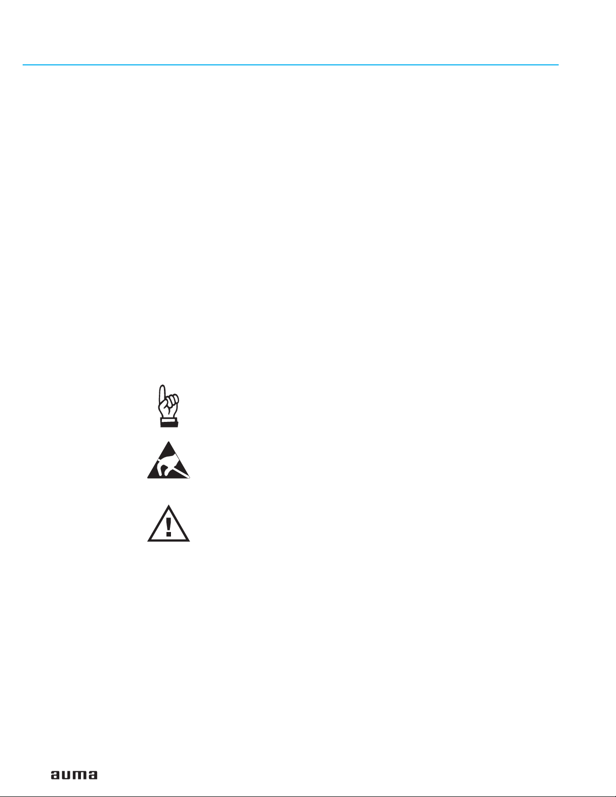
This pictograph means: Note!
“Note” marks activities or procedures which have major influence on the correct
operation. Non-observance of these notes may lead to consequential damage.
This pictograph means: Electrostatically endangered parts!
If this pictograph is attached to a printed circuit board, it contains parts which may
be damaged or destroyed by electrostatic discharges. If the boards need to be
touched during setting, measurement, or for exchange, it must be assured that
immediately before a discharge through contact with an earthed metallic surface
(e.g. the housing) has taken place.
This pictograph means: Warning!
“Warning” marks activities or procedures which, if not carried out correctly, can
affect the safety of persons or material.
2. Short description AUMA multi-turn actuators type SA 07.1 – SA 48.1 and SAR 07.1 – SAR 30.1 have
a modular design. The limitation of travel is realized via limit switches in both end
positions. Torque seating is also possible in both end positions. The type of seating is
determined by the valve manufacturer.
4
Page 5
Multi-turn actuators SA 07.1 – SA 48.1 / SAR 07.1 – SAR 30.1
Operation instructions AUMA NORM
3. Technical data
Table 1: Multi-turn actuator SA 07.1 – SA 48.1 /SAR 07.1 – SAR 30.1
Multi-turn actuators AUMA NORM require electric controls. AUMA offers the controls AUMA MATIC AM or AUMATIC AC for the
sizes SA(R) 07.1 - SA(R) 16.1. These can also easily be mounted to the actuator at a later date.
Features and functions
Type of duty
Motors Standard: 3-ph AC asynchronous motor, type IM B9 according to IEC 34
Insulation class Standard: F, tropicalized
Motor protection Standard: Thermoswitches (NC)
Supply voltage Refer to motor nameplate
Self-locking yes; for output speeds from 4,8 to 108 rpm and from size SA 35.1 for output speeds from 4,8 to 26 rpm
Limit switching Counter gear mechanism for end positions CLOSED and OPEN
Torque switching adjustable torque switching for direction OPEN and CLOSE
Non-intrusive setting
(option)
Position feedback signal,
analogue (options)
Torque feedback signal,
analogue (option)
Mechanical position
indicator (option)
Running indication (option) Blinker transmitter
Heater in switch
compartment
Motor heater (option) SA(R) 07.1 – 10.1: 12.5 W
Manual operation Manual drive for setting and emergency operation, handwheel does not rotate during electrical
Electrical connections Standard: SA(R) 07.1 – 16.1: AUMA plug/socket connector with screw type connection,
Threads for cable glands Standard: NPT-threads
Terminal plan Terminal plan according to commission number included in delivery
1)
Standard: SA Short time duty S2 - 15 min
SAR Intermittent duty S4 - 25 %
Option: SA Short time duty S2 - 30 min
SAR Intermittent duty S4 -50 %
Intermittent duty S5 - 25 %
Options: 1-ph AC motor, type IM B14 according to IEC 34
DC shunt motor, type IM B14 according to IEC 34
DC compound motor, type IM B14 according to IEC 34
Special motors
Option: H, tropicalized
Option: PTC thermistors (according to DIN 44082)
for 1 to 500 turns per stroke (optional for 1 to 5,000 turns per stroke)
Standard: Tandem switch (2 NC and 2 NO) for each end position; switches galvanically isolated
Options: Single switch (1 NC and 1 NO) for each end position
Triple switch (3 NC and 3 NO) for each end position, switches galvanically isolated
Intermediate position switch (DUO limit switching)
Standard: Single switch (1 NC and 1 NO) for each direction
Options: Tandem switch (2 NC and 2 NO) for each direction, switches galvanically isolated
Magnetic limit and torque transmitter MWG for the sizes SA 07.1 – SA 48.1
(only possible in combination with actuator controls AUMATIC)
for 1 to 500 turns per stroke or for 10 to 5,000 turns per stroke
Potentiometer or 0/4 – 20 mA
For further details see separate data sheet
Only in combination with magnetic limit and torque transmitter MWG and actuator controls
AUMATIC
Continuous indication, adjustable indicator disc with symbols OPEN and CLOSED
Standard: self-regulating PTC heater, 5 – 20 W, 110 – 250 V DC/AC
Options: 24 – 48 V DC/AC or 380 – 400 V AC
A resistance type heater (5 W, 24 V DC) is installed in the actuator in combination with the actuator
controls AUMA MATIC or AUMATIC.
SA(R) 14.1 – 16.1: 25 W
SA(R) 25.1 – 30.1: 50 W
SA 35.1 – 48.1: 50 W
operation.
Option: Handwheel lockable
SA(R) 25.1 – 48.1: Control connections on AUMA plug/socket connector,
motor connection via terminals
Option: for special motors: Motor connection directly via terminal board at the motor
Options: Pg-threads, G-threads
1) Based on 68 °F ambient temperature and at an average load with running torque according to Technical data SA(R).
5
Page 6
Multi-turn actuators SA 07.1 – SA 48.1 / SAR 07.1 – SAR 30.1
AUMA NORM Operation instructions
Service conditions
Output drive types A, B1, B2, B3, B4 according ISO 5210 (A, B2, B4 according to MSS SP-102)
A, B, D, E according to DIN 3210
C according to DIN 3338
Special output drives: AF, AK, AG, IB1, IB3
Enclosure protection
according to EN 60 529
Corrosion protection Standard: KN Suitable for installation in industrial units,
Finish coating Standard: Two part acrylic polyurethane
Color Standard: Dark grey (DB 702, similar to RAL 9007)
Ambient temperature
3)
Vibration resistance
according to IEC 60068-2-6
Lifetime
4)
Other information
Reference documents Product description “Electric multi-turn actuators SA”
Standard: IP 67
2)
Options: IP 68
IP 67-DS (Double Sealed)
IP 68-DS (Double Sealed)
(Double Sealed = additional protection of the interior of the housing
against ingress of dust and dirt when removing the plug)
in water or power plants with a low pollutant concentration
Options: KS Suitable for installation in occasionally or permanently aggressive
atmosphere with a moderate pollutant concentration (e.g. in
wastewater treatment plants, chemical industry)
KX Suitable for installation in extremely aggressive atmosphere with high
humidity and high pollutant concentration
KX-G Same as KX, however aluminium-free version (outer parts)
Option: Other colours are possible on request
Standard: SA – 20 to + 80 °C/ – 20 to + 175 °F
SAR – 25 to + 60 °C/ – 20 to + 140 °F
Options: SA – 40 to + 60 °C/ – 40 to + 140 °F (low temperature)
– 50 to + 60 °C/ – 58 to + 140 °F (extreme low temperature)
– 60 to + 60 °C/ – 75 to + 140 °F (extreme low temperature)
– 0 to + 120 °C/ + 32 to + 250 °F (high temperature)
SAR – 40 to + 60 °C/ – 40 to + 140 °F (low temperature)
2 g, for 10 to 200 Hz (only for sizes SA(R) 07.1 – SA(R) 16.1 without controls)
Resistant to vibrations during start-up or for failures of the plant.
However, a fatigue strength may not be derived from this.
Valid for multi-turn actuators in version AUMA NORM (with AUMA plug/socket connector, without
actuator controls). Not valid in combination with gearboxes
SA 07.1 – SA 10.1 20,000 operating cycles (OPEN - CLOSE - OPEN)
with 30 turns per stroke
SA 14.1 – SA 16.1 15,000 operating cycles
SA 25.1 – SA 30.1 10,000 operating cycles
SA 35.1 – SA 48.1 5,000 operating cycles
SAR 07.1 – SAR 10.1
SAR 14.1 – SAR 16.1
SAR 25.1 – SAR 30.1
4)
5 millon starts
4)
3.5 million starts
4)
2.5 million starts
Dimension sheets SA(R)
Electrical data sheets SA/SAR
Technical data sheets SA/SAR
2) For 3-phase asynchronous motors in enclosure protection IP 68, higher corrosion protection KS or KX is strongly recommended. Additionally, for enclosure
protection IP 68, we recommend to use the double sealed terminal compartment DS.
For 1-phase AC motors, DC motors, or special motors, the enclosure protection according the name plate applies.
3) Versions with RWG up to max. to + 158 °F
4) The lifetime depends on the load and the number of starts. A high starting frequency will rarely improve the modulating accuracy. To reach the longest possible
maintenance and fault-free operation time, the number of starts per hour chosen should be as low as permissible for the process.
6
Page 7
Multi-turn actuators SA 07.1 – SA 48.1 / SAR 07.1 – SAR 30.1
Operation instructions AUMA NORM
4. Transport, storage and packaging
4.1 Transport
Fitting the handwheel: For transport purposes, handwheels from a diameter of 400 mm (1 inch
.
For transport to place of installation, use sturdy packaging.
.
Do not attach ropes or hooks to the handwheel for the purpose of lifting by hoist.
.
If multi-turn actuator is mounted on valve, attach ropes or hooks for the purpose
of lifting by hoist to valve and not to multi-turn actuator.
corresponds to 25.4 mm) are supplied separately.
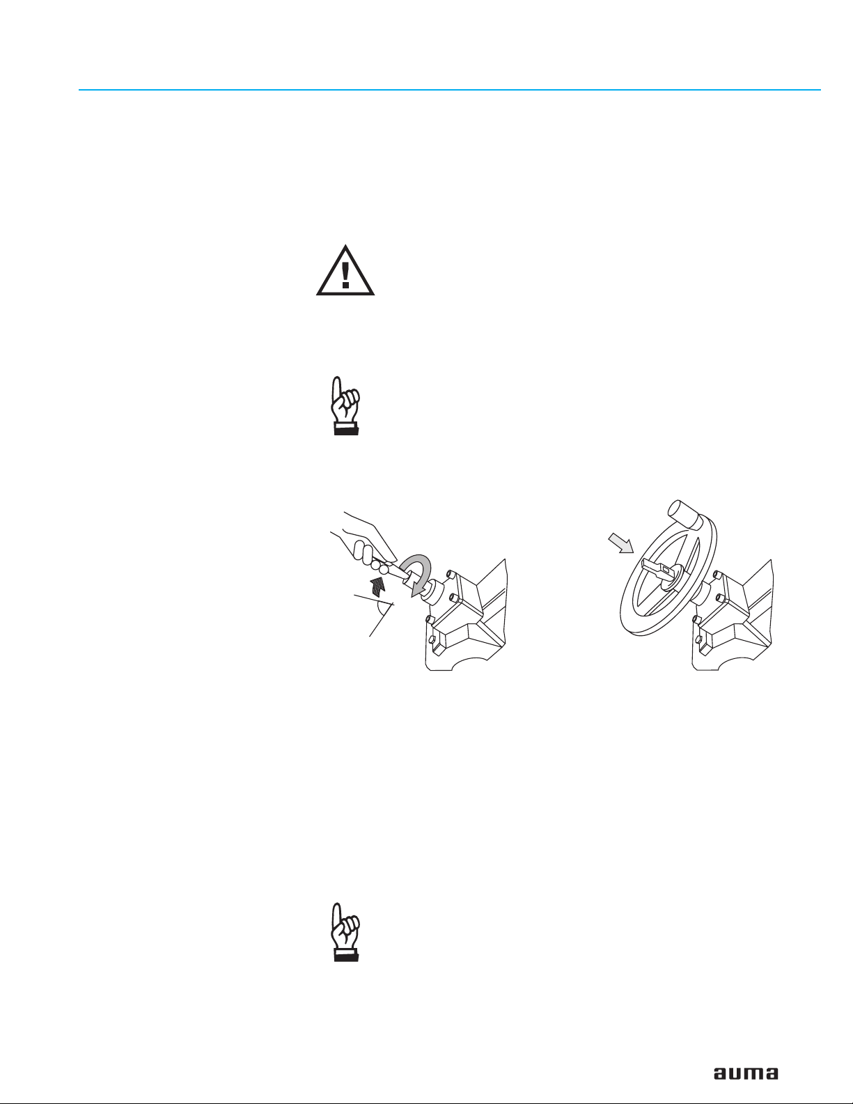
Engage manual operation prior to mounting the handwheel! If the
manual operation is not engaged, damages can occur at the
change-over mechanism.
.
Engage manual operation (figure A-1):
Manually lift the red change-over lever while slightly turning the shaft back and
forth until manual operation engages. The manual operation is correctly engaged
if the change-over lever can be lifted by approx. 85°.
Manual force is sufficient for operating the change-over lever. It is
not necessary to use an extension. Excessive force may damage
the change-over mechanism.
.
Install the hand wheel over the red change-over lever on to the shaft (figure A-2).
.
Secure handwheel using the snapring supplied.
4.2 Storage
Figure A-1 Figure A-2
85°
.
Store in well-ventilated, dry room.
.
Protect against floor dampness by storage on a shelf or on
a wooden pallet.
.
Cover to protect against dust and dirt.
.
Apply suitable corrosion protection agent to uncoated surfaces.
If multi-turn actuators are to be stored for a long time (more than 6 months), in
addition, the following points must imperatively be observed :
.
Prior to storage: Protect uncoated surfaces, in particular the output drive parts
and mounting surface, with long-term corrosion protection agent.
.
Check for corrosion approximately every 6 months. If first signs of corrosion
show, apply new corrosion protection.
After mounting, connect actuator immediately to electrical system,
so that the heater prevents condensation.
4.3 Packaging Our products are protected by special packaging for the transport ex works. The
packaging consists of environmentally friendly materials which can easily be
separated and recycled.
7
Page 8
Multi-turn actuators SA 07.1 – SA 48.1 / SAR 07.1 – SAR 30.1
AUMA NORM Operation instructions
We use the following packaging materials: wood, cardboard, paper and
Polyurethane foam. For the disposal of the packaging material, we recommend
recycling and collection centers.
5. Mounting to valve/gearbox
Mounting is most easily done with the valve shaft/gearbox shaft pointing vertically
upward. But mounting is also possible in any other position.
The multi-turn actuator leaves the factory in position CLOSED (limit switch
CLOSED tripped).
.
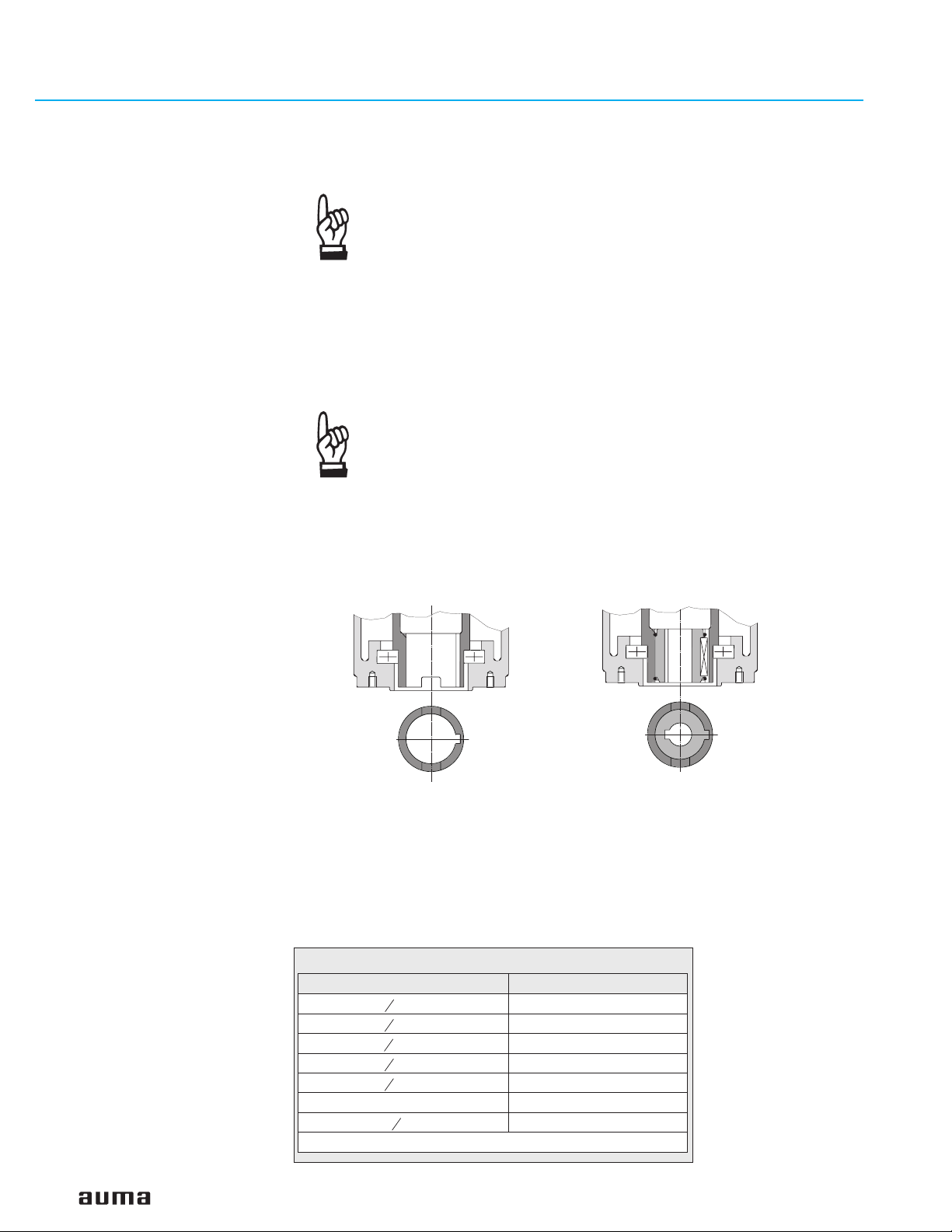
The output drive types B1, B2, B3 or B4 (figure A-3) are delivered with bore and
keyway (usually according to ISO 5210) and are sometimes shipped with bore and
keyway according to customer request.
Figure A-3
.
Prior to mounting the multi-turn actuator must be checked for
damage. Damaged parts must be replaced by original spare
parts.
.
After mounting, check multi-turn actuator for damage to paint
finish. If damage to paint-finish has occurred after mounting, it
has to be touched up to avoid corrosion.
Check if mounting flange fits the valve/gearbox.
Spigot at flanges should be loose fit!
Output drive type B1/B2
Plug sleeve (option)
Output drive type B3/B4
Bore with keyway (standard)
For output drive type A (figure B-1), the internal thread of the stem nut must match
the thread of the valve stem. If not ordered explicitly with thread, the stem nut is
unbored or with pilot bore when delivered. For finish machining of stem nut refer to
next page.
.
Check whether bore and keyway match the input shaft of valve/gearbox.
.
Thoroughly degrease mounting faces at multi-turn actuator and valve/gearbox.
.
Apply a small quantity of grease to input shaft of valve/gearbox.
.
Place actuator on valve/gearbox and fasten. Fasten bolts (quality grade 5, refer
to table 2) evenly crosswise.
Table 2: Standard dry fastening torques for bolts
UNC threads TA(ft lbs)
5
- 18 19
16
3
- 16 33
8
1
- 13 78
2
5
- 11 155
8
3
- 10 255
4
1 - 8 590
1
1
- 7 1,200
4
Conversion factor: 1 Nm corresponds to 1.3529 ft lbs.
8
Page 9
Multi-turn actuators SA 07.1 – SA 48.1 / SAR 07.1 – SAR 30.1
Operation instructions AUMA NORM
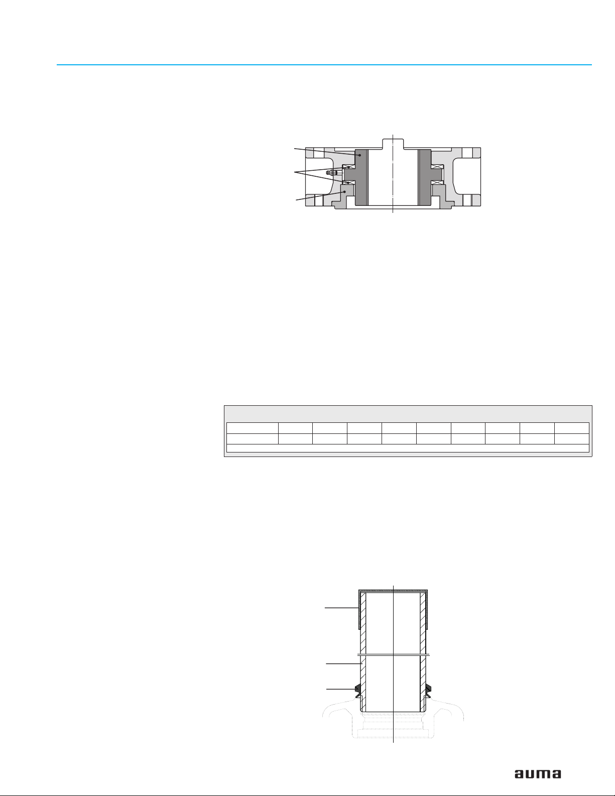
Finish machining of stem nut (output drive type A):
Figure B-1
80.3
80.01/80.02
80.2
The output drive flange does not have to be removed from the actuator.
.
Remove spigot ring (80.2, figure B-1) from mounting flange.
.
Take off stem nut (80.3) together with thrust bearing (80.01) and thrust bearing
races (80.02).
.
Remove thrust bearing and thrust bearing races from stem nut.
.
Drill and bore stem nut and cut thread.
When fixing in the chuck, make sure stem nut runs true!
.
Clean the machined stem nut.
.
Apply Lithium soap EP multi-purpose grease to thrust bearing and races, then
place them on stem nut.
.
Re-insert stem nut with thrust bearings into the mounting flange. Ensure that
dogs are placed correctly in the slots of the hollow shaft.
.
Screw in spigot ring until it is firm against the shoulder.
.
Press Lithium soap EP multi-purpose grease on mineral oil base into the grease
nipple with a grease gun (for quantities, refer to table below):
Output drive type A
Stem nut
Table 3: Grease quantities for lubricating bearings
Output drive A 07.2 A 10.2 A 14.2 A 16.2 A 25.2 A 30.2 A 35.2 A 40.2 A 48.2
Qty1)in g
1) For grease with a density ρ = 900 g/dm3; conversion factor: 1 oz corresponds to 28.35 g
Protection tube for rising valve stem
.
Protection tubes may be supplied loose. Seal thread with hemp, Teflon tape, or
thread sealing material.
.
Screw protection tube (1) into thread (figure B-2) and tighten it firmly.
.
Push down the sealing (2) to the housing.
.
Check whether cap (3) is available and without damage.
Figure B-2: Protection tube for rising valve stem
1.5 g 2 g 3 g 5 g 10 g 14 g 20 g 25 g 30 g
3
1
2
9
Page 10
Multi-turn actuators SA 07.1 – SA 48.1 / SAR 07.1 – SAR 30.1
AUMA NORM Operation instructions
6. Manual operation The actuator may be operated manually for purposes of setting and
commissioning, and in case of motor failure or power failure.
Manual operation is engaged by an internal change-over mechanism.
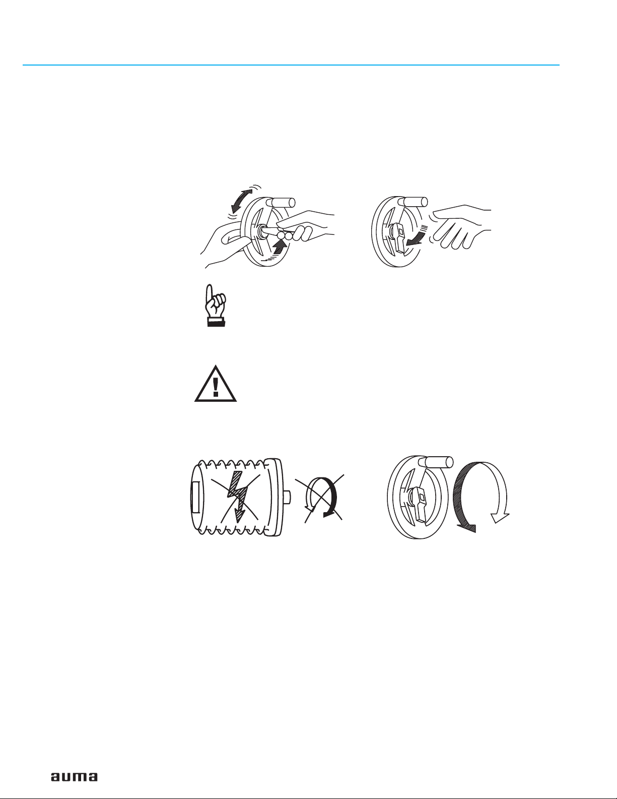
Engaging manual operation:
.
Lift up change-over lever in the center of the handwheel to approx. 85°, while
slightly turning the handwheel back and forth until manual operation engages
(figure C).
Figure DFigure C
Manual force is sufficient for operating the change-over lever. It is
not necessary to use an extension. Excessive force may damage
the change-over mechanism.
.
Release change-over lever (should snap back into initial position by spring
action, figure D), if necessary, push it back manually.
Operating the change-over lever while the motor is running
(figure E) can lead to increased wear at the change-over
mechanism.
Disengaging manual operation:
Figure E Figure F
.
Turn handwheel in desired direction (figure F).
Manual operation is automatically disengaged when the motor is started again.
The handwheel does not rotate during motor operation.
10
Page 11

Multi-turn actuators SA 07.1 – SA 48.1 / SAR 07.1 – SAR 30.1
Operation instructions AUMA NORM
7. Electrical connection Work on the electrical system or equipment must only be carried
out by a skilled electrician themselves or by specially instructed
personnel under the control and supervision of such an electrician
and in accordance with the applicable electrical engineering rules.
7.1 Connection with AUMA plug/socket connector
Figure G-1: Connection
50.0
50.01
51.0
51.01
Figure G-2: Parking frame (accessory)
Parking frame
.
Check whether type of current, supply voltage, and frequency correspond to
motor data (refer to name plate at motor).
.
Loosen bolts (50.01) (figure G-1) and remove plug cover.
.
Loosen screws (51.01) and remove socket carrier (51.0) from plug cover (50.0).
.
Insert cable glands or conduit fittings suitable for connecting cables.
(The enclosure protection stated on the name plate is only ensured if properly
sealed connections are made).
.
Seal cable entries which are not used with sealed threaded plugs.
.
Connect cables according to order-related terminal plan.
.
The terminal plan applicable to the actuator is placed inside the terminal
compartment, the operation instructions are attached to the handwheel in a
weather-proof bag.
A special parking frame (figure G-2) for protection against touching the bare
contacts and against environmental influences is available.
Table 4: Technical data AUMA plug/socket connectors
Technical data Power terminals
No. of contacts max. 6 (3 are used) 1 (leading contact) 50 pins/sockets
Marking U1, V1, W1, U2, V2, W2 according to VDE 1 to 50
Voltage max. 750 V – 250 V
Nominal current max. 25 A –
Type of customer connection Screws Screw for ring lug Screws
Cross section max. 6 mm2(10 AWG) 6 mm2(10 AWG) 2.5 mm2(12 AWG)
Material: Pin/ socket carrier Polyamide
Contacts Brass (Ms)
1) Suitable for copper wires. For aluminium wires it is necessary to contact AUMA.
From size SA(R) 25.1, the motor connection is realised via a separate terminal board
1)
Protective earth Control pins
16 A
Polyamide Polyamide
Brass (Ms)
Brass, tin plated or gold plated (option)
11
Page 12

Multi-turn actuators SA 07.1 – SA 48.1 / SAR 07.1 – SAR 30.1
AUMA NORM Operation instructions
7.2 Motor connection for the sizes SA(R) 25.1/SAR 30.1 – SA 48.1.
From the size SA(R) 25.1, the power for the motor is connected to separate
terminals. For this, the cover at the motor connection compartment has to be
removed.
The control contacts are connected to the AUMA plug/socket connector.
Cross section motor terminals:
16 mm² to 70 mm² (6 to 2/0 AWG), depending on the actuator size
Figure G-3: Connection to SA(R) 25.1
Cover motor connection compartment
7.3 Motor connection for special motors
AUMA plug/socket connector
For versions with special motors (e.g. DC motors), the connection is
performed directly at the motor (figure G-4).
Figure G-4: Connection special motor
7.4 Delay time The delay time is the time from the tripping of the limit or torque switches to the
motor power being removed. To protect the valve and the actuator, we recommend
a delay time < 50 ms. Longer delay times are possible provided the output speed,
output drive type, valve type, and the type of installation are taken into
consideration.
We recommend to switch off the corresponding contactor directly by the limit or
torque switch.
7.5 Controls made by AUMA In case the required reversing contactors are not to be installed in the control
cabinet, the controls AUMA MATIC or AUMATIC for the sizes SA(R) 07.1 – SA(R)
16.1 can be easily mounted to the actuator at a later date.
For enquiries and more information, please state our commission no. (refer to
actuator name plate).
7.6 Heater AUMA multi-turn actuators have a heater installed as standard. To prevent
condensation, the heater must be connected.
7.7 Motor protection In order to protect against overheating and extreme high temperatures at the
actuator, PTC thermistors or thermoswitches are embedded in the motor winding.
The thermoswitch is tripped as soon as the max. permissible winding temperature
has been reached.
Failure to integrate PTC thermistors or thermoswitches into the control circuit voids
the warranty for the motor.
7.8 Remote position transmitter For the connection of remote position transmitters (potentiometer, RWG) shielded
cables must be used.
12
Page 13

Multi-turn actuators SA 07.1 – SA 48.1 / SAR 07.1 – SAR 30.1
O
SC /LSO
Operation instructions AUMA NORM
7.9 Limit and torque switches
Figure G-5
SPDT
DPDT
I Single switch
RD
BK
BK
RD
II Tandem switch
RD
BK
RD
BK
DSR 1 / DÖL 1
WSR 1 / WÖL 1
TSC 1 / TSO 1
LSC 1 / LSO 1
RD 2
BK 2
RD 2
BK 2
DSR / DÖL
WSR / WÖL
TSC / TSO
L
Only the same potential can be switched on the two circuits (NC/NO contact) of a
limit or torque switch. If different potentials are to be switched simultaneously,
tandem switches are required.
To ensure correct actuator indications, the leading contacts of the tandem switches
must be used for that purpose and the lagging contacts for motor switching off.
Table 5: Technical data for limit and torque switches
Mechanical
lifetime = 2 x 10
NONCNC
Type of current Switch rating I
1-phase AC
(ind. load) cos phi = 0,8
DC
(resistive load)
with gold plated
contacts
Current min. 4 mA, max. 400 mA
N
6
starts
max
30 V 125 V 250 V
5 A 5 A 5 A
2 A 0,5 A 0.4 A
min. 5 V, max. 50 V
7.10 Fitting of the cover After connection:
.
Insert the socket carrier (51.0) into the plug cover (50.0) and fasten it with
screws (51.01).
.
Clean sealing faces at the plug cover and the housing.
.
Check whether O-ring is in good condition.
.
Apply a thin film of non-acidic grease (e.g. Vaseline) to the sealing faces.
.
Replace plug cover (50.0) and fasten bolts (50.01) evenly crosswise.
.
Fasten conduit connections with the specified torque to ensure the required
enclosure protection.
13
Page 14

Multi-turn actuators SA 07.1 – SA 48.1 / SAR 07.1 – SAR 30.1
AUMA NORM Operation instructions
8. Opening the switch compartment
8.1 Removing the switch compartment cover
To be able to carry out the following settings (sections 9. to 15.), the switch
compartment must be opened and, if installed, the indicator disc must be removed.
These settings are only valid for “clockwise closing”, i.e. driven shaft turns
clockwise to close the valve.
Work on the electrical system or equipment must only be carried
out by a skilled electrician themselves or by specially instructed
personnel under the control and supervision of such an electrician
and in accordance with the applicable electrical engineering rules.
.
Loosen 4 bolts and take off the cover at the switch compartment
(figures H) .
Fig. H-1: Cover with indicator glass
Bolts
Fig. H-2: Cover without indicator glass
8.2 Pulling off the indicator disc (option)
.
If installed, pull off indicator disc (figure J). Open end wrench
may be used as lever.
Figure J: Pulling off the indicator disc
DSR
WDR
Indicator disc
14
Page 15

Multi-turn actuators SA 07.1 – SA 48.1 / SAR 07.1 – SAR 30.1
Operation instructions AUMA NORM
9. Setting the limit switching
9.1 Setting the end position CLOSED (black section)
.
Turn handwheel clockwise until valve is closed.
.
After having reached the end position, turn back handwheel by approximately ½
a turn (overrun). During test run, check overrun and, if necessary, correct setting
of the limit switching.
.
Press down and turn setting spindle A (figure K-1) with a flat blade
screw driver in direction of arrow, thereby observe pointer B.
While a ratchet is felt and heard, the pointer B moves 90° every time.
When pointer B is 90° from mark C, continue turning slowly. When pointer B has
reached the mark C, stop turning and release setting spindle. If you override the
tripping point inadvertently (ratchet is heard after the pointer has rotated),
continue turning the setting spindle in the same direction and repeat setting
process.
Figure K-1: Control unit
T
B
C
9.2 Setting the end position OPEN (white section)
.
Turn handwheel counterclockwise until valve is open, then turn back by
approximately ½ a turn.
.
Press down and turn setting spindle D (figure K-1) with a flat blade screw driver
in direction of arrow, thereby observe pointer E.
While a ratchet is felt and heard, the pointer E moves 90° every time.
When pointer E is 90° from mark F, continue turning slowly. When pointer E has
reached the mark F, stop turning and release setting spindle. If you override the
tripping point inadvertently (ratchet is heard after the pointer has rotated),
continue turning the setting spindle in the same direction and repeat setting
process.
9.3 Checking the limit switches The red test buttons T and P (figure K-1) are used for manual operation of the limit switches.
.
Turning T in direction of the arrow LSC (WSR) triggers limit switch CLOSED.
.
Turning P in direction of the arrow LSO (WÖL) triggers limit switch OPEN.
A
D
P
E
F
15
Page 16

Multi-turn actuators SA 07.1 – SA 48.1 / SAR 07.1 – SAR 30.1
AUMA NORM Operation instructions
10. Setting the DUO limit switching (option)
Any application can be switched on or off via the two intermediate position
switches.
For setting, the switching point (intermediate position) must be
approached from the same direction as later during
electrical operation.
10.1 Setting the direction CLOSE (black section)
.
Move valve to desired intermediate position.
.
Press down and turn setting spindle G (figure K-2) with a flat blade
screw driver in direction of arrow, thereby observe pointer H.
While a ratchet is felt and heard, the pointer H moves 90° every time.
When pointer H is 90° from mark C, continue turning slowly. When pointer H has
reached the mark C, stop turning and release setting spindle. If you override the
tripping point inadvertently (ratchet is heard after the pointer has rotated),
continue turning the setting spindle in the same direction and repeat setting
process.
Figure K-2: Control unit
T
C
H
10.2 Setting the direction OPEN (white section)
.
Move valve to desired intermediate position.
.
Press down and turn setting spindle K (figure K-2) with a flat blade
screw driver in direction of arrow, thereby observe pointer L.
While a ratchet is felt and heard, the pointer L moves 90° every time.
When pointer L is 90° from mark F, continue turning slowly. When pointer L has
reached the mark F, stop turning and release setting spindle. If you override the
tripping point inadvertently (ratchet is heard after the pointer has rotated),
continue turning the setting spindle in the same direction and repeat setting
process.
10.3 Checking the DUO switches The red test buttons T and P (Figure K-2) are used for manual operation of DUO limit switches.
.
Turning T in direction of the arrow TSC (DSR) triggers DUO limit switch CLOSED. The
torque switch CLOSED is actuated at the same time.
.
Turning P in direction of the arrow TSO (DÖL) triggers DUO limit switch OPEN.The
torque switch OPEN is actuated at the same time.
G
K
L
P
F
16
Page 17

Multi-turn actuators SA 07.1 – SA 48.1 / SAR 07.1 – SAR 30.1
Operation instructions AUMA NORM
11. Setting the torque switching
11.1 Setting
.
The set torque must suit the valve!
.
This setting should only be changed with the consent of the
valve manufacturer!
Figure L: Torque switching heads
Setting CLOSED Setting OPEN
Ft. Lbs
.
Loosen both lock screws O at the torque dial (figure L).
.
Turn torque dial P to set it to the required torque.
Examples:
Figure L shows the following setting:
.
Tighten lock screws O again
indication in ft lbs
15
25
45
35
35 ft lbs for direction CLOSE
25 ft lbs for direction OPEN
.
The torque switches can also be operated in manual
operation.
.
The torque switching acts as overload protection over full travel,
also when stopping in the end positions by limit switching.
P
O
Ft. Lbs
15
45
35
25
11.2 Checking the torque switches
The red test buttons T and P (figure K-2) are used for manual operation of the
torque switches:
.
Turning T in direction of the arrow TSC (DSR) triggers torque switch CLOSED.
.
Turning P in direction of the arrow TSO (DÖL) triggers torque switch OPEN.
.
If a DUO limit switching (optional) is installed in the actuator, the intermediate
position switches will be operated at the same time.
17
Page 18

Multi-turn actuators SA 07.1 – SA 48.1 / SAR 07.1 – SAR 30.1
AUMA NORM Operation instructions
12. Test run
12.1 Check direction of rotation
.
If provided, place indicator disc on shaft.
The direction of rotation of the indicator disc (figure M-1) indicates the direction
of rotation of the output drive.
.
If there is no indicator disc, the direction of rotation can also be observed on the
hollow shaft. For this, remove screw plug (no. 27) (figure M-2).
Figure M-1: Indicator disc
CLOSED
.
Move actuator manually to intermediate position or to sufficient distance from
end position.
.
Switch on actuator in direction CLOSE and observe the direction of rotation:
If the direction of rotation is wrong, switch off immediately
Then, correct phase sequence at motor connection. Repeat test run.
Table 6:
Direction of rotation of the indicator disc:
counterclockwise correct
Direction of rotation of the hollow shaft:
clockwise correct
OPEN
Figure M-2: Opening the hollow shaft
27
S1/S2
12.2 Check limit switching
.
Move actuator manually into both end positions of the valve.
.
Check if limit switching is set correctly. Hereby observe that the appropriate
switch is tripped in each end position and released again after the direction of
rotation is changed. If this is not the case, the limit switching must first be set, as
described from page 15.
If no other options (sections 13. to 15.) require setting:
.
Close switch compartment (see page 23, section 16.).
18
Page 19

Multi-turn actuators SA 07.1 – SA 48.1 / SAR 07.1 – SAR 30.1
Operation instructions AUMA NORM
13. Setting the potentiometer (option)
– For remote indication –
.
Move valve to end position CLOSED.
.
If installed, pull off indicator disc.
.
Turn potentiometer (E2) clockwise until stop is felt.
End position CLOSED corresponds to 0 %, end position OPEN to 100 %.
.
Turn potentiometer (E2) back a little.
Due to the ratio of the reduction gearings for the position
transmitter the complete resistance range is not always utilized for
the whole travel. Therefore, an external possibility for adjustment
(setting potentiometer) must be provided.
.
Perform fine-tuning of the zero point at external setting potentiometer (for remote
indication).
Figure N: Control unit
E2
19
Page 20

Multi-turn actuators SA 07.1 – SA 48.1 / SAR 07.1 – SAR 30.1
AUMA NORM Operation instructions
14. Setting the electronic position transmitter RWG (option)
– For remote indication or external controls –
After mounting the multi-turn actuator to the valve, check setting by measuring the
output current (see sections 14.1 or 14.2) and re-adjust, if necessary.
Table 7: Technical data RWG 4020
Terminal plans KMS TP_ _ 4 / _ _ _
3- or 4-wire system
Output current I
Power supply
max. input
current
max. load R
U
I 24 mA at 20 mA
0 – 20 mA, 4 – 20 mA 4 – 20 mA
a
v
B
24 V DC, ± 15 %
regulated
output current
600 Ω (Uv - 14 V) /20 mA
The position transmitter board (figure P-1) is located under the cover plate
(figure P-2).
KMS TP _ 4 _ / _ _ _
KMS TP _ 5 _ / _ _ _
2-wire system
14 V DC + (I x RB),
max. 30 V
20 mA
Figure P-1: Position transmitter board
20
Page 21

Multi-turn actuators SA 07.1 – SA 48.1 / SAR 07.1 – SAR 30.1
Operation instructions AUMA NORM
14.1 Setting for 2-wire system 4 – 20 mA and 3-/4-wire system 0 – 20 mA
.
Connect voltage to electronic position transmitter.
.
Move valve to end position CLOSED.
.
If installed, pull off indicator disc.
.
Connect ammeter for 0 – 20 mA to measuring points (figure P-2).
Cover plate
Meas. point (+)
0/4 – 20 mA
The circuit (external load) must be connected (max. load R
or the appropriate connections at the terminals (refer to
terminal plan) must be jumpered, otherwise no value can be
measured.
.
Turn potentiometer (E2) clockwise to the stop.
.
Turn potentiometer (E2) back a little.
Figure P-2
.
Turn potentiometer “0“ clockwise until output current starts to increase.
.
Turn potentiometer “0“ back until the following value is reached:
for 3- or 4-wire system: approx. 0.1 mA
for 2-wire system: approx. 4.1 mA.
This ensures that the signal remains above the dead and live zero point.
.
Move valve to end position OPEN.
.
Set potentiometer “max.” to end value 20 mA.
.
Approach end position CLOSED again and check minimum value
(0.1 mA or 4.1 mA). If necessary, correct the setting.
“0” (0/4 mA)
“max.” (20 mA)
E2
Meas. point (–)
0/4 – 20 mA
),
B
If the maximum value cannot be reached, the selection of the
reduction gearing must be checked.
21
Page 22

Multi-turn actuators SA 07.1 – SA 48.1 / SAR 07.1 – SAR 30.1
AUMA NORM Operation instructions
14.2 Setting the 3-/4- wire system 4 – 20 mA
.
Connect voltage to electronic position transmitter.
.
Move valve to end position CLOSED.
.
If installed, pull off indicator disc.
.
Connect ammeter for 0 – 20 mA to measuring points (figure P-2).
Cover plate
Meas. point (+)
0/4 – 20 mA
The circuit (external load) must be connected (max. load R
or the appropriate connections at the terminals (refer to
terminal plan) must be jumpered, otherwise no value can be
measured.
.
Turn potentiometer (E2) clockwise to the stop.
.
Turn potentiometer (E2) back a little.
Fig. P-3
.
.
.
.
.
.
.
“0” (0/4 mA)
Turn potentiometer “0“ clockwise until output current starts to increase.
Turn back potentiometer “0“ until a residual current of approx. 0.1 mA is reached.
Move valve to end position OPEN.
Set potentiometer “max.” to end value 16 mA.
Move valve to end position CLOSED.
Set potentiometer “0“ from 0.1 mA to initial value 4 mA.
This results in a simultaneous shift of the end value by 4 mA, so that the range is
now 4 – 20 mA.
Approach both end positions again and check setting. If necessary, correct the
setting.
“max.” (20 mA)
E2
Meas. point (–)
0/4 mA – 20 mA
),
B
22
If the maximum value cannot be reached, the selection of the
reduction gearing must be checked.
Page 23

Multi-turn actuators SA 07.1 – SA 48.1 / SAR 07.1 – SAR 30.1
Operation instructions AUMA NORM
15. Setting the mechanical position indicator (option)
.
Place indicator disc on shaft.
.
Move valve to end position CLOSED.
.
Turn lower indicator disc (figure Q1) until symbol CLOSED is in alignment
with the mark on the cover (figure Q-2).
.
Move actuator to end position OPEN.
.
Hold lower indicator disc CLOSED in position and turn upper disc with symbol
OPEN until it is in alignment with the mark on the cover.
Figure Q-1
Indicator disc
Indicator disc rotates by approximately 180° to 230°at full travel from OPEN to
CLOSED or vice versa.
A suitable reduction gearing was installed in our factory. If the turns per stroke are
changed at a later date, the reduction gearing may have to be exchanged, too.
16. Closing the switch compartment
.
Clean sealing faces of housing and cover
.
Check whether O-ring is in good condition.
.
Apply a thin film of non-acidic grease to the sealing faces.
.
Replace cover on switch compartment and fasten bolts evenly crosswise.
Figure Q-2
Mark
After commissioning, check for damage to paint finish of
multi-turn actuator. If damage to paint-finish has occurred after
mounting, it has to be touched up to avoid corrosion.
23
Page 24

Multi-turn actuators SA 07.1 – SA 48.1 / SAR 07.1 – SAR 30.1
AUMA NORM Operation instructions
17. Enclosure protection IP 68 (option)
Definition According to EN 60 259, the conditions for meeting the requirements of enclosure
protection IP 68 are to be agreed between manufacturer and user.
AUMA actuators and controls in enclosure protection IP 68 meet the following
requirements according to AUMA:
.
Duration of submersion in water max. 72 hours
.
Head of water max. 6 m
.
Up to 10 operations during submersion
.
Modulating duty is not possible during submersion
Enclosure protection IP 68 refers to the interior of the actuators (motor, gearing,
switch compartment, control, and terminal compartment).
For multi-turn actuators, the following has to be observed:
When using output drive types A and AF (stem nut), it cannot be prevented that
water enters the hollow shaft along the valve stem during submersion. This leads
to corrosion. The water also enters the thrust bearings of output drive type A,
causing corrosion and damage of the bearings. The output drive types A and AF
should therefore not be used.
Inspection AUMA actuators and controls in enclosure protection IP 68 undergo a routine
testing for tightness in the factory.
Cable glands
Commissioning When commissioning, the following should be observed:
After submersion
.
For the entries of the motor and control cables appropriate, cable glands in
enclosure protection IP 68 must be used. The size of the cable glands must be
suitable for the outside diameter of the cables, refer to recommendations of the
cable gland manufacturers.
.
As standard, actuators and controls are delivered without cable glands. For
delivery, the threads are sealed with plugs in the factory.
.
When ordered, cable glands can also be supplied by AUMA at an additional
charge. For this, it is necessary to state the outside diameter of the cables.
.
The cable glands must be sealed against the housing at the thread with an
O-ring.
.
It is recommended to additionally apply a liquid sealing material
(Loctite or similar).
.
Sealing faces of housing and covers must be clean
.
O-rings of the covers must not be damaged
.
A thin film of non-acidic grease should be applied to sealing faces
.
Covers should be tightened evenly and firmly
.
Check actuator.
.
In case of ingress of water, dry actuator correctly and check for proper function.
24
Page 25

Multi-turn actuators SA 07.1 – SA 48.1 / SAR 07.1 – SAR 30.1
Operation instructions AUMA NORM
18. Maintenance After maintenance, check multi-turn actuator for damage to paint finish. If damage
to paint-finish has occurred, it has to be touched up to avoid corrosion. Original
paint in small quantities can be supplied by AUMA.
AUMA multi-turn actuators require low-level maintenance.
Precondition for reliable service is correct commissioning.
Seals made of elastomers are subject to ageing and must therefore regularly be
checked and, if necessary, exchanged.
It is also very important that the O-rings at the covers are placed correctly and
cable glands tightened firmly to prevent ingress of dirt or water.
We recommend additionally:
.
If rarely operated, perform a test run about every 6 months. This ensures that the
actuator is always ready to operate.
.
Approximately six months after commissioning and then every year, check bolts
between actuator and valve/gearbox for tightness. If required, tighten applying
the torques given in table 2, page 8.
.
For multi-turn actuators with output drive type A: at intervals of approx. 6 months
from commissioning press in Lithium soap EP multi-purpose grease on mineral
oil base at the grease nipple with grease gun (quantity see table 3, page 9).
19. Lubrication
.
The gear housing is filled with lubricant in the factory.
.
A grease change is recommended after the following operation time:
.
If rarely operated, after 10 – 12 years
.
If operated frequently, after 6 – 8 years
Lubrication of the valve stem must be done separately.
25
Page 26

Multi-turn actuators SA 07.1 – SA 48.1 / SAR 07.1 – SAR 30.1
AUMA NORM Operation instructions
20. Disposal and recycling
AUMA actuators have an extremely long lifetime. However, they have to be
replaced at one point in time.
The actuators have a modular design and may therefore easily be disassembled,
separated, and sorted according to materials, i.e.:
.
electronic scrap
.
various metals
.
plastics
.
greases and oils
The following generally applies:
.
Collect greases and oils during disassembly. As a rule, these substances are
hazardous to water and must not be released into the environment.
.
Arrange for controlled waste disposal of the disassembled material or for
separate recycling according to materials.
.
Observe the regional regulations for waste disposal.
21. Service AUMA offers extensive services such as maintenance and inspection for actuators.
The AUMA service department can be reached at:
phone: 724-743-AUMA (2862)
fax: 724-743-7411
email: mailbox@auma-usa.com
www.auma-usa.com or www.auma.com.
26
Page 27

Multi-turn actuators SA 07.1 – SA 48.1 / SAR 07.1 – SAR 30.1
Operation instructions AUMA NORM
22. Spare parts list Multi-turn actuator SA(R) 07.1 – SA(R) 16.1 with plug/socket connector
Sample name plate
14
85.0
85.001
85.001
B3 / B4 / E
90.0
90.001
90.001
- Actuator type
- Commission number
- Comm./ sales order number
Works/ Serial number
- Protection type
Torque range
in CLOSE/ OPEN
- Lubricant
- Temperature range
153.2
153.1
153.3
155.0
153.0
153.5
012
30.0
S2
10.0
S2
9.0
D
152.1
152.2
AUMA ACTUATORS INC.
PITTSBURGH PA USA
SA 07.1-FA10
Com No:1309533
No: 3302MD 19302
n: 11 rpm
T open: 7-22Nm
T close 7-22Nm
Lubr.: F1 NEMA4
Temp -25°C/+80°C
50.0
160.2
55.0
160.1
5.37
5.8
151.0
5.0
S2
5.7
39
58.0
S1 / S2
27
S1 / S2
5.12
5.32
3.0
6
S2
80.0
80.001
80.001
80.3
S2
A
2.0
S2
S2
S1 / S2
51.0
54.0
53.0
S2
S2
S2
79.0
.1
16.1
S2
79.0
S2
07.1 – SAR 14.1
7.1 – SA 14.1
52.0
20.0
56.0
57.0
S1 / S2
70.0
S2
19.0
17.0
24
019
020
25.0
24.0 / 23.0
59.0
70.1
053
18
22.0
49.0
1.0
105.0
S1 / S2
107
100
106.0
61.0
60.0
156.0
15.0
B1 / C
27
Page 28

Multi-turn actuators SA 07.1 – SA 48.1 / SAR 07.1 – SAR 30.1
AUMA NORM Operation instructions
Notes:
When placing orders for spare parts, it is essential to mention type of actuator and our commission number (refer to
actuator name plate). Delivered spare parts may slightly vary from the representation in these instructions.
No. Type Designation
012
019
020
053
1.0
2.0
3.0
5.0
5.12
5.32
5.37
5.7
5.8
6
9.0
10.0
14
15.0
17.0
18
19.0
20.0
22.0
23.0
24
24.0
25.0
27
30.0
39
49.0
50.0
51.0
52.0
53.0
54.0
55.0
56.0
57.0
E
Notched pin
E
Cheese head screw
E
Clamping washer
E
Countersunk screw
B
Housing assly.
B
Flange, bottom assly.
B
Hollow shaft assly. (without worm wheel)
B
Worm shaft assly.
E
Set screw
E
Coupling pin
B
Pull rod assly.
E
Motor coupling
B
Manual drive coupling assly.
E
Worm wheel
B
Planetary gear assly. for manual drive
B
Retaining flange assly.
E
Change-over lever
B
Cover for switch compartment assly.
B
Torque lever assly.
E
Gear segment
B
Crown wheel assly.
B
Swing lever assly.
B
Drive pinion II for torque switching assly.
B
Drive wheel for limit switching assly.
E
Drive wheel for limit switching
B
Intermediate wheel for limit switching assly.
E
Locking plate
E
Screw plug
B
Handwheel with ball handle assly.
E
Screw plug
1)
B
Motor plug, socket assly.
B
Cover assly.
B
Socket carrier assly. (with sockets)
B
Pin carrier (without pins)
B
Socket for control
B
Socket for motor
B
Socket for protective earth
B
Pin for control
B
Pin for motor
No. Type Designation
58.0
59.0
60.0
61.0
70.0
70.1
79.0
80.0
80.001
80.3
85.0
85.001
90.0
90.001
100
105.0
106.0
107
151.0
152.1
152.2
153.0
153.1
153.2
153.3
153.5
155.0
156.0
160.1
160.2
S1
S2
B
Wire for protective earth
1)
1)
2)
3)
3
3)
3)
3)
3)
3)
3)
3)
3)
3)
3)
3)
3)
3)
3)
3)
3)
Pin for motor and thermoswitch
B
in motor plug
Control unit assly. (but without torque head,
B
without switches)
B
Torque switching head
B
Motor
Motor pin carrier
B
(without pins)
B
Planetary gearing for motor drive assly.
Output drive form A assly.
B
(without thread in stem nut)
E
Thrust bearing set
E
Stem nut form A (without thread)
B
Output drive B3
E
Snap ring
B
Output drive D
E
Snap ring
Switch for limit/ torque switching
B
(including pins at wires)
Blinker transmitter including pins at wires
B
(without impulse disc and insulation plate)
B
Stud bolt for switches
E
Spacer
B
Heater
B
Potentiometer (without slip clutch)
B
Slip clutch for potentiometer
B
RWG assly.
Potentiometer for RWG
B
(without slip clutch)
B
Slip clutch for RWG
B
Electronic board RWG
B
Wires for RWG
B
Reduction gearing
B
Mechanical position indicator
E
Protection tube(without cap)
E
Cap for stem protection tube
S
Seal kit, small
S
Seal kit, large
1) SA 16.1 with output speeds of 32 to 216 rpm or SAR 16.1 with output speeds of 32 and 54 rpm without
plug/ socket connector; motor directly wired to pin carrier (No. 52.0) .
2) not available for all output speeds
3) not included in basic equipment
28
Page 29

Multi-turn actuators SA 07.1 – SA 48.1 / SAR 07.1 – SAR 30.1
Operation instructions AUMA NORM
23. Spare parts list Multi-turn actuator SA 25.1 – SA 48.1/SAR 25.1 – SAR 30.1
Works/ Serial number
Torque range
Sample name plate
- Actuator type
- Commission number
- Comm./ sales order number
AUMA ACTUATORS INC.
PITTSBURGH PA USA
SA 07.1-FA10
Com no:1309533
No: 3302MD 19302
n: 11 rpm
- Protection type
T open: 7-22Nm
in CLOSE/ OPEN
- Lubricant
T close 7-22Nm
Lubr.: F1 NEMA4
- Temperature range
Temp -25°C/+80°C
29
Page 30

Multi-turn actuators SA 07.1 – SA 48.1 / SAR 07.1 – SAR 30.1
AUMA NORM Operation instructions
Notes:
When placing orders for spare parts, it is essential to mention type of actuator and our commission number (refer to
actuator name plate). Delivered spare parts may slightly vary from the representation in these instructions.
No. Type Designation
1.026
1.038
1.1
1.17
1.19
1.22
1.23
1.24
1.25
1.27
1.28
2.58
2.59
3
3.05
3.11
3.6
3.7
3.8
4.2
4.3
5
5.1
5.2
6
7.012
7.14
7.50
8.36
8.37
9.33
9.51
9.55
E
Quad ring / radial seal
E
O-ring
B
Housing assly.
B
Torque lever assly.
B
Crown wheel assly.
B
Drive pinion II for torque switching assly.
B
Drive wheel for limit switching assly.
Intermediate wheel for limit switching
B
assly.
E
Locking plate
E
Screw plug
E
Bearing bush
B
Motor
●
B
Planetary gear assly. for motor drive
B
Drive shaft assly.
E
Dowel pin
B
Pull rod assly.
B
Worm wheel assly.
E
Motor coupling
B
Manual drive coupling assly.
B
Flange, bottom assly.
B
Hollow shaft assly.
B
Planetary gear assly. for manual drive
E
Mounting flange
B
Hand wheel shaft assly.
B
Swing lever assly
E
Notched pin
E
Change-over lever
B
Handwheel with ball handle assly.
Control unit assly. (but without torque
B
head, without switches)
B
Switch compartment cover
B
Terminals for motor connection
B
Protective earth connection
Cover for motor connection compartment
B
assly.
No. Type Designation
54.0
55.0
56.0
57.0
58.0
61.0
80.0 *
80.001*
80.3 *
85.0 *
85.001*
100
105
106.0
107
151.0
152.1 *
152.2 *
153.0 *
153.1 *
153.2 *
153.3 *
155.0 *
156.0 *
160.1 *
160.2 *
S1
S2
B
Socket for motor
B
Socket for protective earth
B
Pin for control
B
Pin for motor
B
Wire for protective earth
B
Torque switching head
Output drive form A assly.
B
(without thread in stem nut)
S
Thrust bearing set
E
Stem nut form A (without thread)
B
Output drive form B3 assly.
E
Snap ring
Switch for limit/ torque switching
B
(including pins at wires)
Blinker transmitter including pins at wires
B
(without impulse disc and insulation plate)
B
Stud bolts for switches
E
Spacer
B
Heater
B
Potentiometer (without slip clutch)
B
Slip clutch for potentiometer
B
RWG assly.
B
Potentiometer for RWG (without slip clutch)
B
Slip clutch for RWG
B
Printed board for RWG
B
Reduction gearing
B
Mechanical position indicator
E
Protection tube (without cap)
E
Cap
S
Seal kit (small)
S
Seal kit (large)
50.0
51.0
52.0
53.0
● not available for all output speeds
* not included in basic equipment
B
Plug cover assly.
B
Socket carrier assly. (with sockets)
B
Pin carrier (without pins)
B
Socket for control
30
Page 31

Multi-turn actuators SA 07.1 – SA 48.1 / SAR 07.1 – SAR 30.1
Operation instructions AUMA NORM
Index
C
Corrosion protection 7
D
DUO limit switching 16
E
Electrical connection 11
Electronic position transmitter
RWG 20
2-wire system 21
3-/ 4-wire system 22
Enclosure protection IP 68 24
F
Finish machining of stem nut 9
H
Handwheel 10
Heater 12
I
Indicator disc 23
L
Limit switches 13
Limit switching 15,16
Lubrication 25
M
Maintenance 4
Manual operation 10
Mechanical position indicator 23
Motor protection 12
Mounting to valve/gearbox 8
O
Output drive types 8
P
Packaging 7
Position indicator 23
Position transmitter RWG 20
Potentiometer 19
Protection tube 9
PTC thermistors 12
R
Remote indication 19,20
S
Safety instructions 4
Service 26
Spare parts list 27,29
Storage 7
T
Tandem switches 13
Technical data 5
Test run 18
Thermoswitches 12
Torque setting 17
Transport 7
Tripping torque 17
31
Page 32

North American Sales and Service:
US Headquarters and Factory:
AUMA Actuators, Inc.
100 Southpointe Blvd.
Canonsburg PA 15317
Tel: 724-743-AUMA (2862)
Fax: 724-743-4711
email: mailbox@auma-usa.com
www.auma-usa.com
Regional Offices:
Northeast (Maryland and New York)
Southeast (South Carolina)
Midwest (Illinois)
Midwest (Kansas)
Houston (Texas)
West Coast (Northern and Southern California)
Representatives and Distributors
Anchorage
Atlanta
Baltimore
Baton Rouge
Birmingham
Boston
Charlotte
Chicago
Cincinati
Corpus Christi
Dallas
Denver
Detroit
Hawaii
Houston
Indianapolis
Kansas City
Los Angeles
Mexicali (Mexico)
Mexico City
Milwaukee
Minneapolis
Montana
Monterrey (Mexico)
New York
Omaha
Orlando
Philadelphia
Phoenix
Pittsburgh
Rochester
Salt Lake City
San Diego
San Francisco
San Juan
Seattle
St. Louis
Toronto
Tulsa
International Headquarters:
AUMA Riester GmbH & Co. KG
Müllheim/ Germany
www.auma.com
International Sales and Service:
South America:
Argentina
Brazil
Chile
Colombia
Peru
Venezuela
Europe:
Austria
Benelux
Czech Republic
Denmark
Finland
France
Greece
Hungary
Italy
Norway
Poland
Portugal
Russia
Spain
Sweden
Switzerland
Turkey
Ukraine
United Kingdom
Africa
Egypt
South Africa
Asia, Australia
Australia
China
Hong Kong
India
Japan
Korea
Kuwait
Oman
Qatar
Singapore
Taiwan
Thailand
UAE
For the name and phone number of the office
nearest you, call us at 724-743-2862 or visit our
website at www.auma-usa.com/saleserv.htm
2005-06-27
Y000.001/015/us/1.05
 Loading...