

Page 1
Electric multi-turn actuators
SA 07.1 – SA 30.1
SAR 07.1 – SAR 30.1
with actuator controls
AUMA MATIC AM 01.1 / AM 02.1
for flange type FA
®
Operation instructions
Page 2

Multi-turn actuators SA 07.1 – SA 30.1/ SAR 07.1 – SAR 30.1
with actuator controls AUMA MATIC AM 01.1 / AM 02.1 Operation instructions
Scope of these instructions:
These instructions valid for multi-turn actuators of the type range
SA 07.1 – SA 30.1/ SAR 07.1 – SAR 30.1 with
the actuator controls AM 01.1 / AM 02.1.
These operation instructions are only valid for “clockwise closing”,
i.e. driven shaft turns clockwise to close the valve.
Table of contents Page
1. Safety instructions 4
1.1 Range of application 4
1.2 Electrical connection 4
1.3 Maintenance 4
1.4 Warnings and notes 4
2. Short description 5
3. Technical data 6
4. Additional information to the wiring diagram legend 9
5. Transport, storage and packaging 10
5.1 Transport 10
5.2 Storage 10
5.3 Packaging 11
6. Mounting to valve/ gearbox 12
7. Mounting positions of the local controls 14
8. Electrical connection 15
8.1 Connection with AUMA plug/ socket connector (S, SH, SE) 17
9. Manual operation 19
10. Operation and indications of the local controls 20
11. Opening the switch compartment 22
11.1 Removing the cover from the switch compartment 22
11.2 Pulling off the indicator disc (option) 22
12. Setting the limit switching 23
12.1 Setting end position CLOSED (black section) 23
12.2 Setting end position OPEN (white section) 23
12.3 Checking the limit switches 23
13. Setting the DUO limit switching (option) 24
13.1 Setting direction CLOSE (black section) 24
13.2 Setting direction OPEN (white section) 24
13.3 Checking the DUO limit switches 24
14. Setting the torque switching 25
14.1 Setting 25
14.2 Checking the torque switches 25
15. Test run 26
15.1 Checking the direction of rotation 26
15.2 Checking the setting of the limit switching 27
15.3 Checking the type of seating 27
15.4 Checking the PTC tripping device (option) 27
16. Setting the potentiometer (option) 29
2
Page 3

Multi-turn actuators SA 07.1 – SA 30.1/ SAR 07.1 – SAR 30.1
Operation instructions with actuator controls AUMA MATIC AM 01.1 / AM 02.1
Page
17. Setting the electronic position transmitter RWG (option) 30
17.1 Setting 2-wire system 4 – 20 mA and 3- /4-wire system 0 – 20 mA 31
17.2 Setting 3- / 4- wire system 4 – 20 mA 32
18. Setting the mechanical position indicator (option) 33
19. Closing the switch compartment 33
20. Actuator controls AUMA MATIC 34
20.1 Functions of the diagnosis LEDs on the interface board (standard version) 34
20.2 Programming the logic board 35
20.3 EMERGENCY - OPEN and EMERGENCY - CLOSE signal (option) 36
21. Electronic positioner (option) 37
21.1 Technical data 37
21.2 Setting 37
21.2.1 Setting type of signal 39
21.2.2 Setting actuator behavior on loss of signal 40
21.3 Positioner adjustment for end position CLOSED (standard version) 41
21.4 Positioner adjustment for end position OPEN (standard version) 43
21.5 Setting the sensitivity 43
21.6 Positioner adjustment for end position OPEN (inverse operation) 45
21.7 Positioner adjustment end position CLOSED (inverse operation) 46
21.8 Positioner in Split Range version (option) 47
21.8.1 Split Range: description of functions 47
21.8.2 Programming 47
21.8.3 Positioner adjustment for Split Range 47
22. Timer (option) 49
22.1 Functions of the diagnosis LEDs (timer) 49
22.2 Setting start and end of stepping mode via DUO limit switching (option) 50
22.3 Setting ON and OFF times 51
23. Fuses 52
23.1 Fuses within the actuator controls 52
23.2 Motor protection 54
24. Enclosure protection IP 68 (option) 55
25. Maintenance 56
26. Lubrication 56
27. Disposal and recycling 56
28. Service 57
29. Spare parts list Multi-turn actuator SA(R) 07.1 – SA(R) 16.1 60
30. Spare parts list controls AUMA MATIC 62
Index 63
Addresses of AUMA offices and representatives 64
3
Page 4
Multi-turn actuators SA 07.1 – SA 30.1/ SAR 07.1 – SAR 30.1
with actuator controls AUMA MATIC AM 01.1 / AM 02.1 Operation instructions
1. Safety instructions
1.1 Range of application
AUMA actuators are designed for the operation of industrial valves, e.g.
globe valves, gate valves, butterfly valves and ball valves.
For other applications, please consult us. The manufacturer is not liable for any
possible damage resulting from use in other than the designated applications.
Such risk lies entirely with the user.
Observance of these operation instructions is considered as part of the controls’/ actuator’s designated use.
1.2 Electrical connection
During electrical operation, certain parts inevitably carry lethal voltages. Work
on the electrical system or equipment must only be carried out by a skilled electrician themselves or by specially instructed personnel under the control and
supervision of such an electrician and in accordance with the applicable electrical engineering rules.
1.3 Maintenance
The maintenance instructions (refer to page 56) must be observed, otherwise a
safe operation of the actuator is no longer guaranteed.
1.4 Warnings and notes
Failure to observe the warnings and notes may lead to serious injuries or damage. Qualified personnel must be thoroughly familiar with all warnings and notes
in these operation instructions.
Correct transport, proper storage, mounting and installation, as well as careful
commissioning are essential to ensure a trouble-free and safe operation.
During operation, the multi-turn actuator warms up and surface temperatures
> 140 °F may occur. Check the surface temperature prior to contact in order to
avoid burns.
The following references draw special attention to safety-relevant procedures in
these operation instructions. Each is marked by the appropriate pictograph.
This pictograph means: Note!
“Note” marks activities or procedures which have major influence on the correct
operation. Non-observance of these notes may lead to consequential damage.
This pictograph means: Electrostatically endangered parts!
If this pictograph is attached to a printed circuit board, it contains parts which
may be damaged or destroyed by electrostatic discharges. If the boards need to
be touched during setting, measurement, or for exchange, it must be assured
that immediately before a discharge through contact with a grounded metallic
surface (e.g. the housing) has taken place.
This pictograph means: Warning!
“Warning” marks activities or procedures which, if not carried out correctly, can
affect the safety of persons or material.
4
Page 5
Multi-turn actuators SA 07.1 – SA 30.1/ SAR 07.1 – SAR 30.1
Operation instructions with actuator controls AUMA MATIC AM 01.1 / AM 02.1
2. Short description
AUMA multi-turn actuators of the type range SA 07.1 – SA 30.1/SAR 07.1 –
SAR 30.1 are driven by an electric motor and controlled by the actuator controls AUMA MATIC AM 01.1/ AM 02.1, which is included in the scope of delivery.
A handwheel is provided for manual operation.
The limitation of travel is realized via limit switches in both end positions. Torque
seating is also possible in both end positions. The type of seating is determined
by the valve manufacturer.
Both the multi-turn actuator and the controls have a modular design, i.e. they
are designed in accordance with the principle of a modular construction system.
This means that each actuator or each controls are individually manufactured
and combined for a specific valve automation task. An order-specific commission number, printed on the name plate, is assigned to each actuator/ controls.
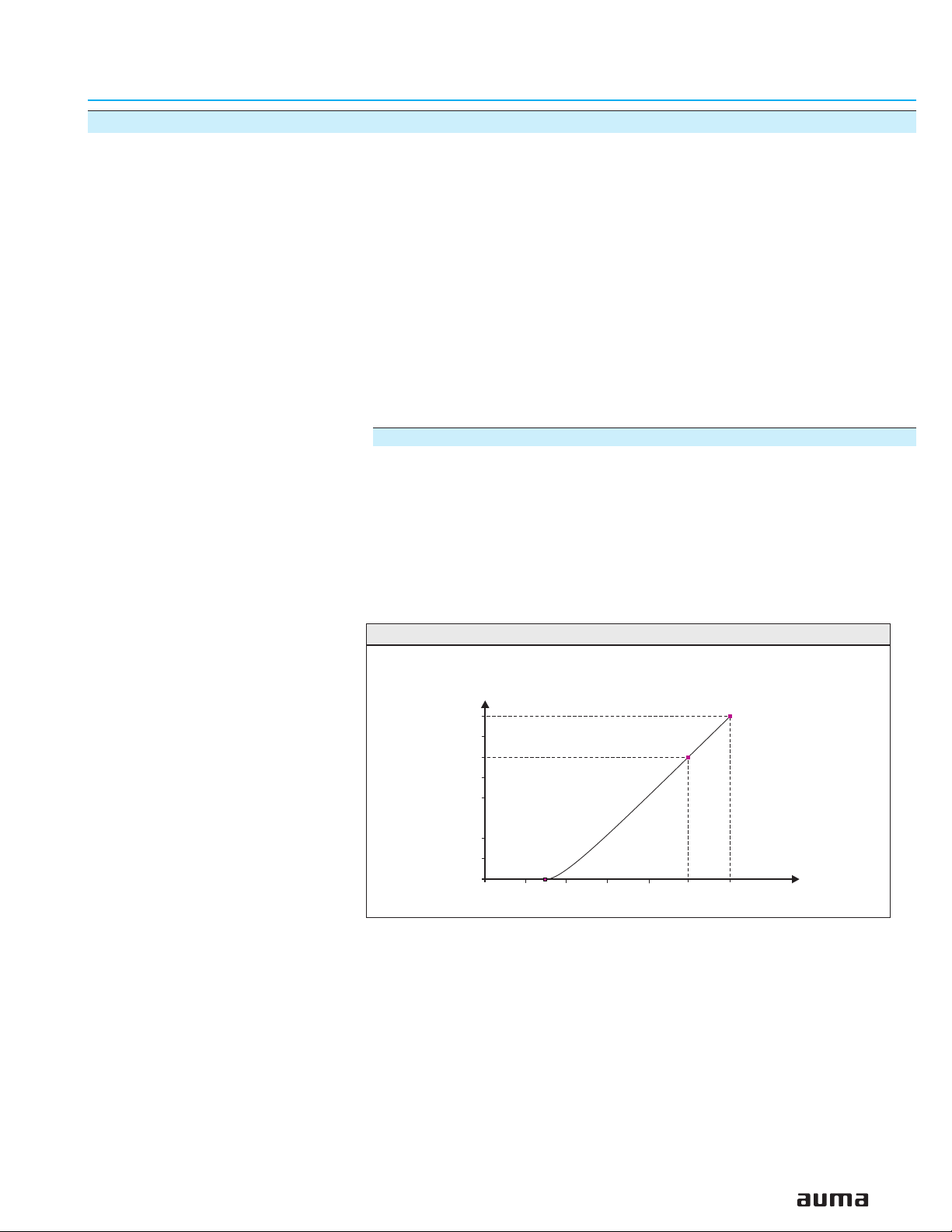
Commissioning
Please note that for low temperature versions (– 58 °F), the controls requires a
heat-up time.
This heat-up time is applicable in case the actuator and the controls are not live
and have cooled down to ambient temperature. In case commissioning has to
be performed under these conditions, the following heat-up times have to be
observed:
60 min. at – 58 °F
80 min. at – 76 °F
Figure A: Heat-up time chart
t [min.]
80
70
60
50
40
30
20
10
0
0–14–4
–22
–40 –76
–58
ϑ [°F]
5
Page 6
Multi-turn actuators SA 07.1 – SA 30.1/ SAR 07.1 – SAR 30.1
with actuator controls AUMA MATIC AM 01.1 / AM 02.1 Operation instructions
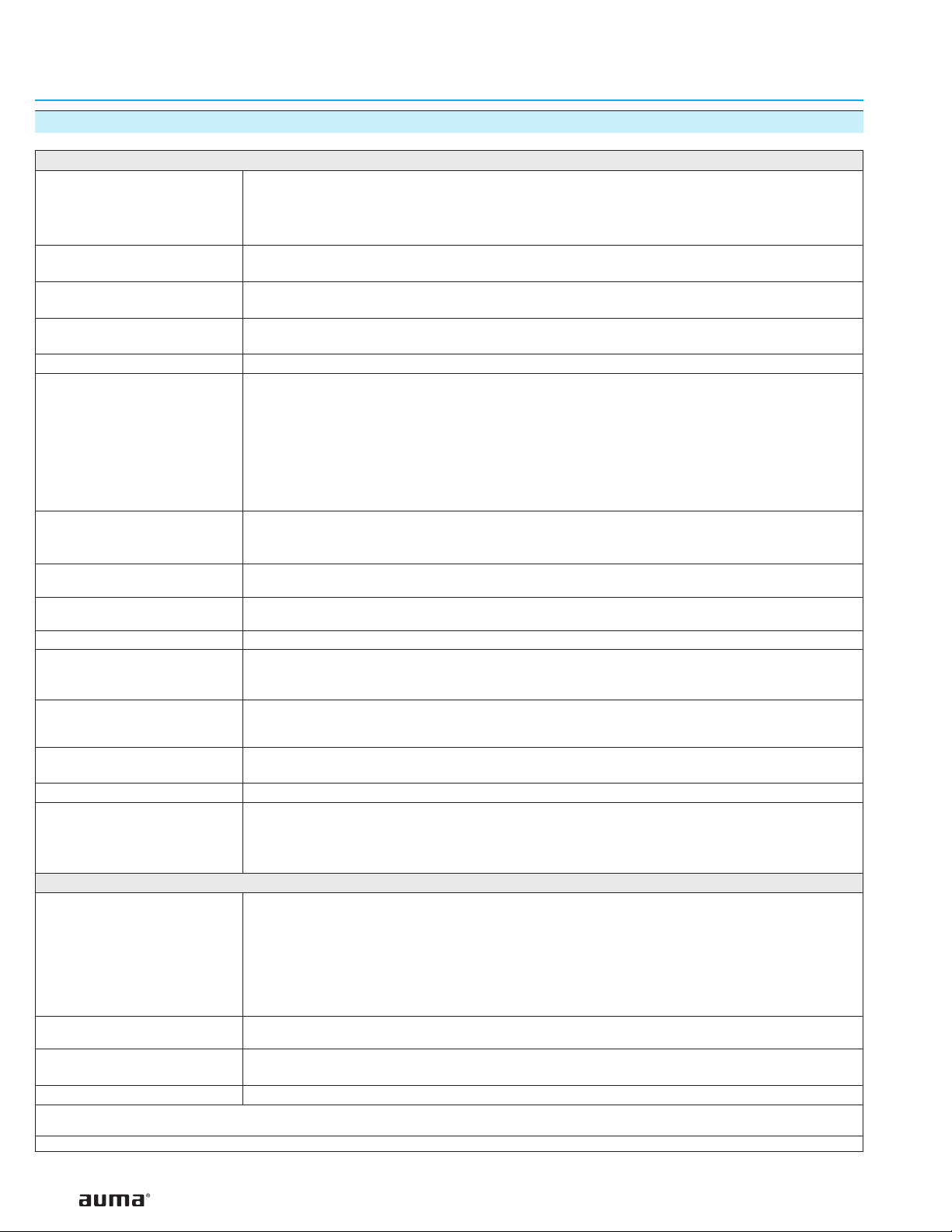
3. Technical data
Features and functions
Type of duty
Motors Standard: 3-ph AC asynchronous motor, type IM B9 according to IEC 34
Insulation class Standard: F, tropicalized
Motor protection Standard: Thermoswitches (NC)
Self-locking Yes, for output speeds from 5.6 to 108 rpm
Limit switching Counter gear mechanism for end positions CLOSED and OPEN
Torque switching Infinitely adjustable torque switching for direction OPEN and CLOSE
Position feedback signal,
analogue (options)
Mechanical position indicator
(option)
Running indication (option) Blinker transmitter
Heater in switch compartment Standard: Resistance type heater with 5 W, 24 V DC
Motor heater (option) SA(R) 07.1 – 10.1: 12.5 W
Manual operation Manual drive for setting and emergency operation, handwheel does not rotate during electrical operation.
Connection to controls AUMA plug/ socket connector with screw type connection
Output drive types A, B1, B2, B3, B4 according to EN ISO 5210
1)
Standard: SA Short time duty S2 - 15 min
SAR Intermittent duty S4 - 25 %
Option: SA Short time duty S2 - 30 min
SAR Intermittent duty S4 - 50 %
Intermittent duty S5 – 25 %
Option: Special motors
Option: H, tropicalized
Option: PTC thermistors (according to DIN 44082)
for 1 to 500 turns per stroke (optional for 1 to 5,000 turns per stroke)
Standard: Tandem switch (2 NC and 2 NO) for each end position
Options: Single switch (1 NC and 1 NO) for each end position,
switches galvanically isolated
Triple switch (3 NC and 3 NO) for each end position,
switches galvanically isolated
Intermediate position switch (DUO limit switching),
adjustable for any intermediate position
Standard: Single switch (1 NC and 1 NO) for each direction
Options: Tandem switch (2 NC and 2 NO) for each direction, switches galvanically isolated
Potentiometer or 0/4 – 20 mA (RWG)
For further details, see separate data sheet
Continuous indication, adjustable indicator disc with symbols OPEN and CLOSED
Options: Self-regulating PTC heater, 5 – 20 W
24 – 48 V AC/DC, 110 – 250 V AC/DC or 380 – 400 V AC
SA(R) 14.1 – 16.1: 25 W
SA(R) 25.1 – 30.1: 50 W
Option: Handwheel lockable
A, B, D, E according to DIN 3210
C according to DIN 3338
Special output drives: AF, AK, AG, IB1, IB3
Power supply, mains frequency
and current consumption
External supply of the
electronics (option)
Rated power Refer to motor name plate
Overvoltage category Category III
1) Based on 68 °F ambient temperature and at an average load with running torque according to Technical data SA or SAR
For mains voltage and mains frequency, refer to name plates at the controls and the motor
Permissible variation of the nominal voltage: ± 10 %
Permissible variation of the mains frequency: ± 5 %
Motor current consumption: Refer to motor name plate
Current consumption of the controls depending on the mains voltage:
100 to 120 V AC = max. 600 mA
208 to 240 V AC = max. 300 mA
380 to 500 V AC = max. 150 mA
24 V DC + 20 % / – 15 %,
Observe current consumption of the controls
Note: The controls is designed for the rated power of the actuator
6
Page 7
Multi-turn actuators SA 07.1 – SA 30.1/ SAR 07.1 – SAR 30.1
Operation instructions with actuator controls AUMA MATIC AM 01.1 / AM 02.1
Switchgear Standard: Reversing contactors2)(mechanically and electrically interlocked)
for motor power up to 1.5 kW
Options: Reversing contactors
2)
(mechanically and electrically interlocked)
for nominal motor current up to 18 A (OPEN - CLOSE- duty)
or 16 A (modulating duty)
Thyristor unit3)(recommended for modulating actuators)
for motor power up to 1.5 kW, 500 V AC with internal fuses
for motor power up to 5.5 kW, 500 V AC, external fuses required
Control Standard: Control inputs 115 V AC, OPEN - STOP - CLOSE (via opto-isolator,
with one common), current consumption: approx. 10 mA per input
Observe min. duration of impulse for modulating actuators
Option: Control inputs 24 V DC, OPEN - STOP - CLOSE (via opto-isolator,
with one common), current consumption: approx. 15 mA per input
Output signals Standard: 5 output relays with gold-plated contacts:
4 potential-free NO contacts with one common:
max. 250 V AC, 0.5 A (resistive load)
Standard configuration:
End position OPEN, end position CLOSED, selector switch REMOTE,
selector switch LOCAL
1 potential-free change-over contact, max. 250 V AC, 0.5A (resistive load)
for collective fault signal
Standard configuration:
Torque fault, phase failure, motor protection tripped
Option: Signals in connection with positioner:
End position OPEN, end position CLOSED
(requires tandem switch within actuator)
Selector switch REMOTE, selector switch LOCAL via 2
nd
level
selector switch
1 potential-free change-over contact, max. 250 V AC, 0.5A (resistive load)
for collective fault signal:
Torque fault, phase failure, motor protection tripped
Voltage output Standard: Auxiliary voltage 115 V AC, max. 30 mA for supply of the control inputs,3),
galvanically isolated from internal voltage supply
Option: Auxiliary voltage 24 V DC, max. 50 mA for supply of the control inputs,
galvanically isolated from internal voltage supply
Local controls Standard: Selector switch LOCAL - OFF - REMOTE (lockable in all three positions)
Push buttons OPEN - STOP - CLOSE
3 indication lights:
End position CLOSED (red), collective fault signal (yellow), end position OPEN (green)
Option: Protection cover, lockable
Functions Standard: Switch-off mode adjustable
Limit or torque seating for end position OPEN and end position CLOSED
Overload protection against excessive torques over the whole travel
Excessive torque (torque fault) can be excluded from collective fault signal
Phase failure monitoring with automatic phase correction
Push-to-run operation or self-retaining in REMOTE
Push-to-run operation or self-retaining in LOCAL
Blinker transmitter signal of actuator can be switched on or off (option)
Options: Positioner
4)
:
Nominal position value via analogue input E1 = 0/4 – 20 mA
Adjustable behavior on loss of signal
Adjustable sensitivity (dead band) and pause time
Split Range operation
Motor protection evaluation Standard: Monitoring of the motor temperature in combination with thermoswitches
in the actuator motor
Options: Additional thermal overload relay in the controls in combination with thermoswitches
within the actuator
PTC tripping device in combination with PTC thermistors in the actuator motor
Electrical connection Standard: AUMA plug/ socket connector with screw type connection
Options: Parking frame for wall mounting of the disconnected plug
Protection cover for plug compartment (when plug is removed)
2) The lifetime guaranteed by the manufacturer amounts to min. 2 million cycles. If a higher number of switching cycles is to be expected, thyristor units with virtually
unlimited lifetime should be used
3) Not possible in combination with PTC tripping device
4) Requires position transmitter (potentiometer or RWG) in actuator
7
Page 8
Multi-turn actuators SA 07.1 – SA 30.1/ SAR 07.1 – SAR 30.1
with actuator controls AUMA MATIC AM 01.1 / AM 02.1 Operation instructions
Threads for cable glands Standard: NPT-threads
Options: Pg-threads, G-threads
Wiring diagram Wiring diagram according to commission number included in delivery
Further options for version with RWG in the actuator
Position feedback (option)
Analogue output E2 = 0/4 – 20 mA (load max. 500 Ω)
Service conditions
Enclosure protection according
to EN 60 529
5)
Standard: IP 67
Options: IP 68
IP 67-DS (Double Sealed)
IP 68-DS (Double Sealed)
(Double Sealed = additional protection of the interior of the housing
against ingress of dust and dirt when removing the plug)
Corrosion protection Standard: KN Suitable for installation in industrial units, in water or power plants
with a low pollutant concentration
Options: KS Suitable for installation in occasionally or permanently aggressive
atmosphere with a moderate pollutant concentration
(e.g. in wastewater treatment plants, chemical industry)
KX Suitable for installation in extremely aggressive atmosphere
with high humidity and high pollutant concentration
KX-G Same as KX, however aluminium-free version (outer parts)
Finish coating Standard: Two-component iron-mica combination
Standard color Standard: AUMA silver-grey (similar to RAL 7037)
Option: Other colors are possible on request
Ambient temperature Standard: SA: – 25 °C to + 70 °C
SAR: – 25 °C to + 60 °C
Options: – 40 °C to + 60 °C/ – 40 to 140 °F, low temperature version
– 50 °C to + 60 °C/ – 75 to 140 °F, extreme low temperature version
incl. heating system
– 60 °C to + 60 °C/ – 75 to 140 °F, extreme low temperature version
incl. heating system
Vibration resistance
according to IEC 60 068-2-6
1 g, from 10 Hz to 200 Hz
Resistant to vibrations during start-up or for failures of the plant. However, a fatigue strength may
not be derived from this.
Applies to actuator with actuator controls, not valid in combination with gearboxes
Lifetime SA 07.1 – 10.1: 20,000 operations (OPEN - CLOSE - OPEN) with 30 turns per stroke
SA 14.1 – 16.1: 15,000 operations (OPEN - CLOSE - OPEN) with 30 turns per stroke
SA 25.1 – 30.1: 10,000 operations (OPEN - CLOSE - OPEN) with 30 turns per stroke
SAR 07.1 – 10.1: 5 million operations/ starts
SAR 14.1 – 16.1: 3.5 million operations/ starts
SAR 25.1 – 30.1: 2.5 million operations/ starts
6)
6)
6)
Weight Multi-turn actuator: Refer to Technical data SA/ SAR
Actuator controls: Approx. 7 kg (including AUMA plug/ socket connector)
Accessories
Wall bracket
7)
AUMA MATIC mounted separately from the actuator, including plug/ socket connector.
Connecting cables on request.
Recommended for high ambient temperatures, difficult access, or in case of heavy vibrations
during service.
Further information
Reference documents Product description “Electric multi-turn actuators SA/ SAR”
Product description “Actuator controls AUMA MATIC”
Dimension sheets SA/ SAR “...with integral controls AUMA MATIC”
Technical data sheets AM 01.1/AM 02.1
Technical data sheets SA/ SAR
Electrical data sheets SA/ SAR
5) For 3-phase asynchronous motors in enclosure protection IP 68, higher corrosion protection KS or KX is strongly recommended. Additionally, for enclosure protection
IP 68, we recommend to use the double sealed terminal compartment DS. For special motors, the enclosure protection according to the name plate applies
6) The lifetime of modulating actuators depends on the load and the number of starts. A high starting frequency will rarely improve the modulating accuracy. To reach the
longest possible maintenance and fault-free operation time, the number of starts per hour chosen should be as low as permissible for the process
7) Cable length between actuator and AUMA MATIC max. 100 m. Not suitable for version with potentiometer in the actuator. Instead of the potentiometer, an RWG has
to be used in the actuator
8
Page 9
Multi-turn actuators SA 07.1 – SA 30.1/ SAR 07.1 – SAR 30.1
Operation instructions with actuator controls AUMA MATIC AM 01.1 / AM 02.1
4. Additional information to the wiring diagram legend
Information A:
A running indication is possible if blinker transmitter (S5) is installed
(opening and closing of contacts).
Direction CLOSE: Connections X
Direction OPEN: Connections X
Contacts remain closed in end position.
When connected to an external PLC, the blinking signal can be switched off via
the DIP-switches (table 4, page 35).
Information B:
The type of seating in the end positions is determined by the valve manufacturer. The setting is done at the programming switches S1-2 and S3-2
(see page 35). The tripping of a torque switch in an intermediate position
switches off the actuator and causes a fault signal.
The limit switches serve for signalization when switching off by torque seating.
They need to be set so that the appropriate switch is tripped shortly before
reaching the end position. If the torque switch trips before the limit switch, the
actuator is switched off and a fault signal is generated.
For further programming possibilities, e.g. self-retaining in operation mode
REMOTE, see table 4, page 35.
6 - XK7
K
6 - XK8
K
Information D:
The following faults are registered and can be transmitted to the control room as
a potential-free collective fault signal:
- Power failure
- Phase failure
- Motor protection tripped
- Torque switch tripped in mid-travel.
This signal can be switched off on the logic board, see table 4, page 35.
Information E:
Input signals according to DIN 19 240.
The nominal operation current of inputs X
2, XK3, and XK4 amounts to
K
10 – 15 mA. If the internal voltage 24 V DC is used for remote control, it must
only be connected via potential-free contacts.
Information F:
In case of wrong phase sequence, the running direction is automatically
adjusted. In case of a phase failure, the actuator stops. The fault is indicated at
LED V14 on the interface board (see page 34). For collective fault signal, see
information D.
Information G:
Potential-free contacts are available for signals. The internal control voltage
(X
11 / + 24 V and XK5 / – 24V) must not be used for external lamps, relays,
K
etc.
Please note that this information only pertains to point to point
drawings.
9
Page 10
Multi-turn actuators SA 07.1 – SA 30.1/ SAR 07.1 – SAR 30.1
with actuator controls AUMA MATIC AM 01.1 / AM 02.1 Operation instructions
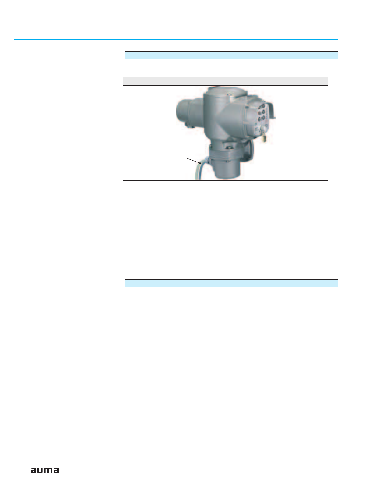
5. Transport, storage and packaging
5.1 Transport
.
For transport to place of installation, use sturdy packaging.
.
Do not attach ropes or hooks to the handwheel for the purpose of lifting by
hoist.
.
If multi-turn actuator is mounted on valve, attach ropes or hooks for the purpose of lifting by hoist to valve and not to multi-turn actuator.
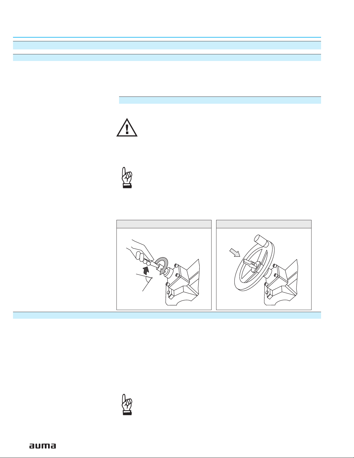
Fitting the handwheel:
For transport purposes, handwheels from a diameter of 400 mm are supplied
separately.
Engage manual operation prior to mounting the handwheel! If
the manual operation is not engaged, damage can occur at the
change-over mechanism.
.
Engage manual operation (figure B-1):
Manually lift the red change-over lever while slightly turning the shaft back and
forth until manual operation engages. The manual operation is correctly
engaged if the change-over lever can be lifted by approx. 85°.
Manual force is sufficient for operating the change-over lever. It
is not necessary to use an extension. Excessive force may
damage the change-over mechanism.
.
Install handwheel over the red change-over lever on to the shaft (figure B-1).
.
Release change-over lever (should snap back into initial position by spring
action, figure B), if necessary, push it back manually.
.
Secure handwheel using the snapring supplied.
5.2 Storage
Figure B-1
85°
.
Store in well-ventilated, dry room.
.
Protect against floor dampness by storage on a shelf or on a wooden pallet.
.
Cover to protect against dust and dirt.
.
Apply suitable corrosion protection agent to uncoated surfaces.
If multi-turn actuators are to be stored for a long time (more than 6 months), the
following points must be observed additionally:
.
Prior to storage: Protect uncoated surfaces, in particular the output drive parts
and mounting surface, with long-term corrosion protection agent.
.
Check for corrosion approximately every 6 months. If first signs of corrosion
show, apply new corrosion protection.
Figure B-2
10
After mounting, connect actuator immediately to electrical
system, so that the heater prevents condensation.
Page 11

Multi-turn actuators SA 07.1 – SA 30.1/ SAR 07.1 – SAR 30.1
Operation instructions with actuator controls AUMA MATIC AM 01.1 / AM 02.1
5.3 Packaging
Our products are protected by special packaging for the transport ex works. The
packaging consists of environmentally friendly materials which can easily be
separated and recycled.
We use the following packaging materials: wood, cardboard, paper, and Polyurethane foam. For the disposal of the packaging material, we recommend recycling and collection centers.
11
Page 12
Multi-turn actuators SA 07.1 – SA 30.1/ SAR 07.1 – SAR 30.1
with actuator controls AUMA MATIC AM 01.1 / AM 02.1 Operation instructions
6. Mounting to valve/ gearbox
.
Prior to mounting the multi-turn actuator must be checked for
damage. Damaged parts must be replaced by original spare
parts.
.
After mounting to valve/ gearbox, touch up any possible damage to paint finish.
The multi-turn actuator leaves the factory in position CLOSED (limit switch
CLOSED tripped).
.
Check if mounting flange fits the valve/ gearbox.
Spigot at flanges should be loose fit!
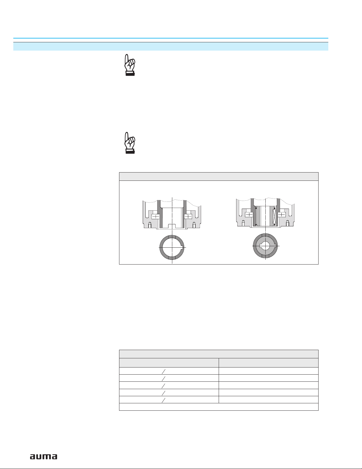
The output drive types B1, B2, B3, or B4 (figure B-3) are delivered with bore
and keyway (usually according to ISO 5210).
Figure B-3
Output drive type B1/B2
Plug sleeve
Output drive type B3/B4
Bore with keyway
For output drive type A (figure C-1), the internal thread of the stem nut must
match the thread of the valve stem. If not ordered explicitly with thread, the stem
nut is unbored or with pilot bore when delivered. For finish machining of stem
nut, refer to next page.
.
Check whether bore and keyway match the input shaft of valve/ gearbox.
.
Thoroughly degrease mounting faces at multi-turn actuator and valve/ gear-
box.
.
Apply a small quantity of grease to input shaft of valve/gearbox.
.
Place actuator on valve/gearbox and fasten. Fasten bolts
(quality min. grade 5, refer to table 1) evenly crosswise.
Table 1: Standard dry fastening torque for bolts
UNC bolts – grade 5 TA(ft lbs.)
5
- 18 19
16
3
- 16 33
8
1
- 13 78
2
5
- 11 155
8
3
- 10 255
4
Conversion factor: 1 Nm corresponds to 1.3529 ft lbs.
12
Page 13
Multi-turn actuators SA 07.1 – SA 30.1/ SAR 07.1 – SAR 30.1
Operation instructions with actuator controls AUMA MATIC AM 01.1 / AM 02.1
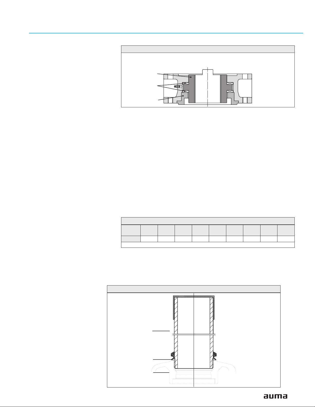
Finish machining of stem nut (output drive type A):
Figure C-1
Output drive type A
Stem nut
80.3
80.01/80.02
80.2
The output drive flange does not have to be removed from the actuator.
.
Remove spigot ring (80.2, figure C-1) from mounting flange.
.
Take off stem nut (80.3) together with thrust bearing (80.01) and thrust bearing races (80.02).
.
Remove thrust bearing and thrust bearing races from stem nut.
.
Drill and bore stem nut and cut thread.
When fixing in the chuck, make sure stem nut runs true!
.
Clean the machined stem nut.
.
Apply Lithium soap EP multi-purpose grease to thrust bearing and races, then
place them on stem nut.
.
Re-insert stem nut with thrust bearings into the mounting flange. Ensure that
dogs are placed correctly in the slots of the hollow shaft.
.
Screw in spigot ring until it is firm against the shoulder.
.
Press Lithium soap EP multi-purpose grease on mineral oil base into the
grease nipple with a grease gun (for quantities, please refer to table):
Table 2: Grease quantities for output drive type A
Output
drive
Qty
1) For greases with a density ρ = 0.9 kg/dm³3; conversion factor: 1 oz corresponds to 28.35 g
Protection tube for rising valve stem
.
Seal thread with hemp, Teflon tape, or thread sealing material.
.
Screw protection tube (1) into thread (figure C-2) and tighten it firmly.
.
Push down the sealing (2) to the housing.
.
Check whether cap (3) is available and without damage.
Figure C-2: Protection tube for rising valve stem
A 07.2 A 10.2 A 14.2 A 16.2 A 25.2 A 30.2 A 35.2 A 40.2 A 48.2
1)
1.5 g 2 g 3 g 5 g 10 g 14 g 20 g 25 g 30 g
3
1
2
13
Page 14
Multi-turn actuators SA 07.1 – SA 30.1/ SAR 07.1 – SAR 30.1
with actuator controls AUMA MATIC AM 01.1 / AM 02.1 Operation instructions
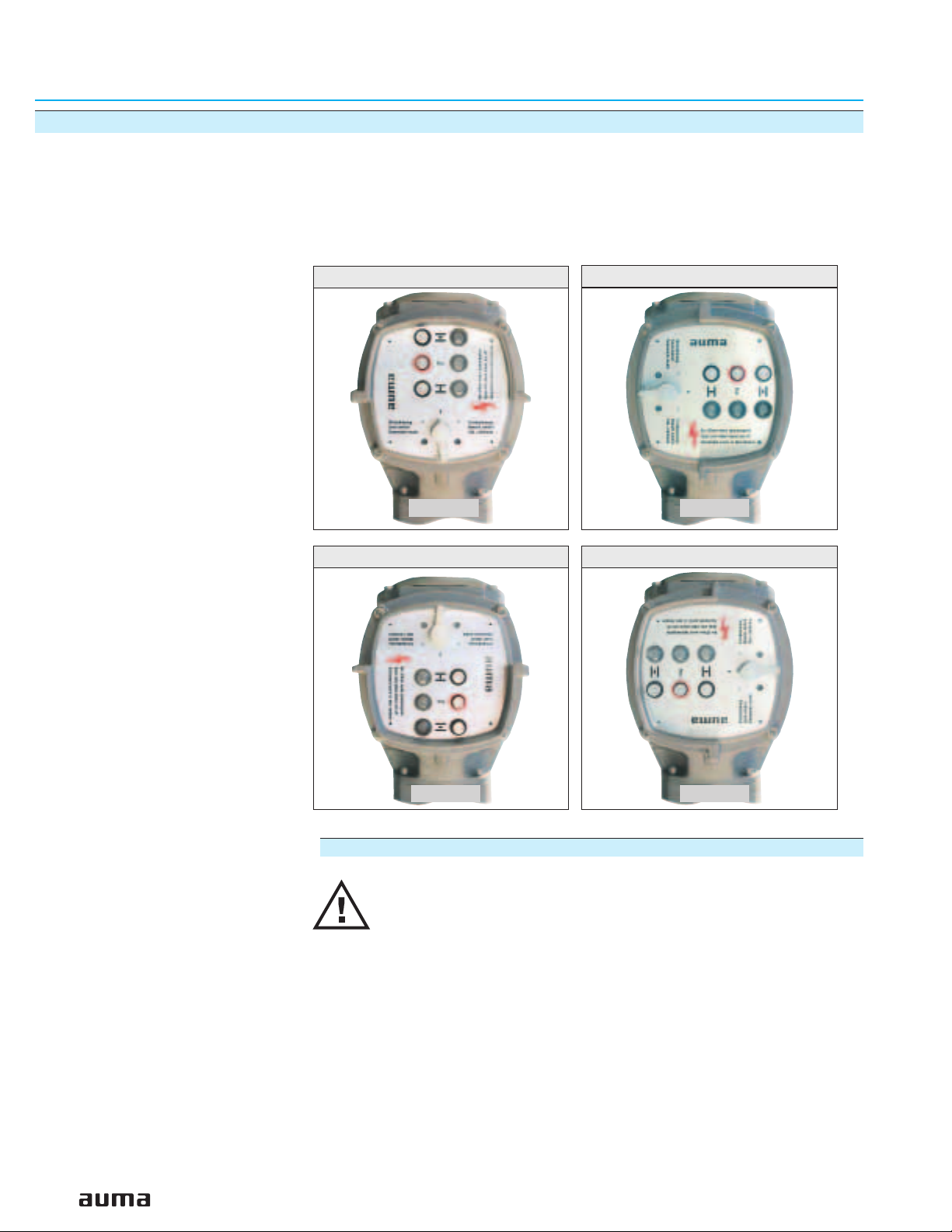
7. Mounting positions of the local controls
The mounting position of the local controls is designed according to the order. If,
after mounting the actuator to the valve or the gearbox on site, the local controls
is in an unfavorable position, the mounting position can easily be changed at a
later date.
Four mounting positions are possible:
Figure D-1: Mounting position A
Actuator
Figure D-3: Mounting position C
Figure D-2: Mounting position B
Actuator
Figure D-4: Mounting position D
14
Actuator
Changing the mounting position
.
Disconnect actuator from the mains before opening.
.
Turn local controls by a maximum of 180°, rotate circuit board
accordingly!
.
Ensure that the wires are neither twisted nor jammed.
.
Loosen 4 bolts and remove the local controls.
.
Turn local controls in one of the four positions and re-place on the actuator,
rotate circuit board accordingly.
.
Clean sealing faces of housing and cover.
.
Check whether O-ring is in good condition.
.
Replace cover on switch compartment and fasten bolts evenly crosswise.
Actuator
Page 15
Multi-turn actuators SA 07.1 – SA 30.1/ SAR 07.1 – SAR 30.1
Operation instructions with actuator controls AUMA MATIC AM 01.1 / AM 02.1
8. Electrical connection
Work on the electrical system or equipment must only be
carried out by a skilled electrician themselves or by specially
instructed personnel under the control and supervision of such
an electrician and in accordance with the applicable electrical
engineering rules.
Wiring diagram
The terminal plan applicable to the actuator is placed inside the terminal compartment, the operation instructions are attached to the handwheel in a
weather-proof bag.
External fuse
For short-circuit protection and for protecting the actuator, fuses and disconnect
switches have to be provided by the customer.
The current values for sizing the switch can be derived from the current consumption of the motor plus the current consumption of the controls.
Motor current consumption:
Refer to name plate on motor (nominal current).
Current consumption of the controls depending on the mains voltage:
100 to 120 V AC = max. 650 mA
208 to 240 V AC = max. 325 mA
380 to 500 V AC = max. 190 mA
The maximum permissible fuse for controls with a rated power of 1.5 kW is 16 A
(gL/ gG), and for controls with a rated power of 7.5 kW, the value amounts to 32
A (gL/ gG).
Cable installation in accordance with EMC
Signal and bus cables are susceptible to interference.
Motor cables are interference sources.
.
Lay cables being susceptible to interference or sources of interference at the
highest possible distance from each other.
.
The interference immunity of signal and bus cables increases if the cables are
laid close to the ground potential.
.
If possible, avoid laying long cables and make sure that they are installed in
areas being subject to low interference.
.
Avoid long parallel paths with cables being either susceptible to interference
or interference sources.
.
For the connection of remote position transmitters (potentiometer, RWG),
screened cables must be used.
Heater
As standard, the control unit of the actuator is equipped with a heater to prevent
condensation within the actuator. Unless ordered otherwise, the heater is internally supplied. For external supply (option), the heater always has to be
connected.
Some actuators are optionally equipped with an additional motor heater. The
motor heater is always externally supplied and has to be connected according
to the wiring diagram.
15
Page 16
Multi-turn actuators SA 07.1 – SA 30.1/ SAR 07.1 – SAR 30.1
with actuator controls AUMA MATIC AM 01.1 / AM 02.1 Operation instructions
Actuator controls on wall bracket (accessory)
For version on wall bracket, please observe the following:
Figure E: AUMA MATIC on wall bracket
Connecting cables
to actuator
.
Versions with potentiometer in the actuator are not suitable. Instead of the
potentiometer, an RWG has to be used in the actuator
.
Permissible cable distance between actuator and AUMA MATIC amounts to a
maximum of 100 m.
.
Factory supplied cables for the connection between actuator and AUMA
MATIC on wall bracket can be obtained from AUMA on request.
In case non factory supplied cables are used, the following additionally has to
be observed:
.
Use suitable flexible and screened connecting cables.
.
Connect the wires in correct phase sequence.
Check the direction of rotation before switching on (see page 26)
Subsequent mounting of the actuator controls on the actuator
In case the actuator and the actuator controls have different commission numbers (refer to name plates), the designations of the terminal plan and the wiring
diagram (KMS . . .) have to match for both devices.
16
Page 17
Multi-turn actuators SA 07.1 – SA 30.1/ SAR 07.1 – SAR 30.1
Operation instructions with actuator controls AUMA MATIC AM 01.1 / AM 02.1
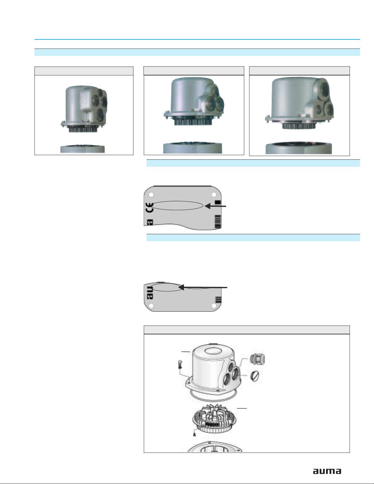
8.1 Connection with AUMA plug/ socket connector (S, SH, SE)
Figure F-1: Version SH (standard) Figure F-2: Version S Figure F-3: Version SE
Before mains connection
Check whether type of current, supply voltage, and frequency comply with
motor data (refer to name plate at motor):
VD00 63-4/45
Art. No.: Z006.413
3 ~ 480V 60Hz
0.09 kW
Y 0.60A
Current type/mains voltage/mains frequency
Opening the terminal compartment
.
Loosen bolts (1) and remove cover (figure G).
.
Loosen screws (2) and remove socket carrier from cover.
.
Insert cable glands suitable for connecting cables
(The enclosure protection stated on the name plate is only ensured if suitable
cable glands are used.).
NEMA 4X
Thermal protection: Th
Insulation class: F
.
Seal cable entries which are not used with suitable plugs.
Figure G: Opening the terminal compartment
Cover
(1)
Enclosure protection
Cable gland and
screw plug
in enclosure protection
according to name plate
Socket carrier
(2)
17
Page 18
Multi-turn actuators SA 07.1 – SA 30.1/ SAR 07.1 – SAR 30.1
with actuator controls AUMA MATIC AM 01.1 / AM 02.1 Operation instructions
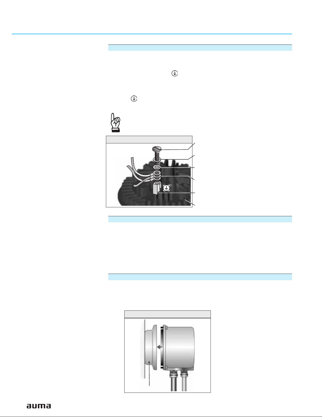
Connecting the cables
.
Connect cables according to order-related wiring diagram.
Cross sections:
- Power terminals (U1, V1, W1, U2, V2, W2) and
protective earth (symbol: )
max. 6 mm² flexible, max. 10 mm² solid
- Control contacts (1 to 50) = max. 2.5 mm²
.
All PE conductors have to be tightened firmly to the PE connection
(symbol: ) using either ring lugs (flexible cables), or lugs (solid cables) (figure H).
Each time the PE connection has been disconnected, it has to
be ensured that the PE conductors are firmly connected.
Figure H: PE connection
Closing the terminal compartment
.
Insert socket carrier into the cover and fasten with screws (2) (figure G).
.
Clean sealing faces at the cover and the housing.
.
Check whether O-ring is in good condition.
.
Apply a thin film of non-acidic grease (e.g. Vaseline) to the sealing faces.
.
Replace cover and fasten bolts (1) evenly crosswise.
.
Fasten cable glands with the specified torque to ensure the required enclosure protection.
Parking frame, protection cover (accessories)
A special parking frame (figure J) for protection against touching the exposed
contacts and against environmental influences is available.
The open terminal compartment can be closed using a protective cover
(not illustrated).
Screw
Washer
Circlip
Protective earth with ring lugs/lugs
PE connection
Socket carrier
18
Figure J: Parking frame (accessory)
Parking frame
Page 19
Multi-turn actuators SA 07.1 – SA 30.1/ SAR 07.1 – SAR 30.1
Operation instructions with actuator controls AUMA MATIC AM 01.1 / AM 02.1
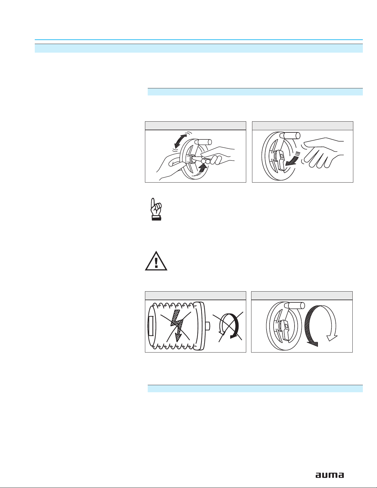
9. Manual operation
The actuator may be operated manually for purposes of setting and commis
sioning and in case of motor failure or power failure.
Manual operation is engaged by an internal change-over mechanism.
Engaging manual operation
.
Lift up change-over lever in the center of the handwheel to approx. 85°, while
slightly turning the handwheel back and forth until manual operation engages
(figure K-1).
Figure K-1
Manual force is sufficient for operating the change-over lever. It
is not necessary to use an extension. Excessive force may
damage the change-over mechanism.
.
Release change-over lever (should snap back into initial position by spring
action, figure K), if necessary, push it back manually.
Figure K-2
-
Operating the change-over lever while the motor is running
(figure L-1) can lead to increased wear at the change-over
mechanism.
Figure L-1 Figure 13-2
.
Turn handwheel into desired direction (figure 13-2).
Disengaging manual operation
Manual operation is automatically disengaged when motor is started again.
The handwheel does not rotate during motor operation.
19
Page 20
Multi-turn actuators SA 07.1 – SA 30.1/ SAR 07.1 – SAR 30.1
t
t
with actuator controls AUMA MATIC AM 01.1 / AM 02.1 Operation instructions
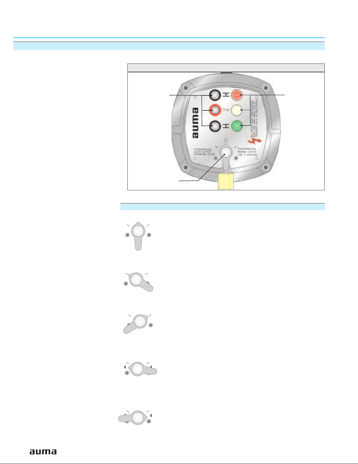
10. Operation and indications of the local controls
Figure M: Local controls
Push buttons
Selector switch
Selector switch
0
I
I
Indication lights
Position OFF (0):
- No remote control possible
- No local control possible
- Actuator remains ready for signalization
signalization (the controls’ power supply is maintained)
III
Test
III
Test
0
I
I
Position Local control (I):
The actuator can be operated locally via the push buttons
OPEN - STOP - CLOSE.
0
I
I
Position Remote control (II):
The actuator can be controlled from remote, e.g. via the control room.
0
I
Position Test (III):
II
Test PTC tripping device (refer to page 27)
Only available in combination with motor protection
III
(PTC thermistor).
Rese
Yellow indication light (fault) is illuminated.
0
I
Position Reset (III):
II
Reset fault signal (yellow indication light) after the motor pro
tection has tripped (refer to page 54).
III
Only available in combination with motor protection
Rese
-
(PTC thermistor).
20
Page 21

Multi-turn actuators SA 07.1 – SA 30.1/ SAR 07.1 – SAR 30.1
Operation instructions with actuator controls AUMA MATIC AM 01.1 / AM 02.1
Push buttons
If the selector switch is in position local control (I), use the push buttons OPEN STOP - CLOSE to operate the actuator locally.
OPEN: Actuator runs in direction OPEN
STOP: Actuator stops
CLOSE: Actuator runs in direction CLOSE
The operation commands OPEN - CLOSE can be used for control during
push-to-run operation or in the self-retaining mode.
In the push-to-run operation, the actuator runs as long as the push button is
pressed.
In the self-retaining mode, the actuator runs to the defined end position, unless
another command has been received beforehand.
For further information on the programming, refer to page 35.
Indication lights
The 3 indication lights give the following signals (standard indication).
Illuminated (red): Actuator is in end position OPEN
Collective fault signal (yellow)
Illuminated (green): Actuator is in end position CLOSED
Collective fault signal:
The collective fault signal (yellow indication light) will be activated if one of the
following events occurs:
.
Torque fault, i.e. the set torque (page 25) was exceeded before reaching an
end position.
.
Motor protection has tripped (refer to page 54), i.e. the motor is overheated.
.
A phase failure (for 3-phase AC motors) has occurred.
.
Test PTC tripping device
Indication lights are blinking:
If the actuator is equipped with a blinker, the indication lights can be used as
running indication.
If the blinker transmitter is active (page 35), the respective indication light blinks
during operation.
21
Page 22

Multi-turn actuators SA 07.1 – SA 30.1/ SAR 07.1 – SAR 30.1
DSR
WDR
with actuator controls AUMA MATIC AM 01.1 / AM 02.1 Operation instructions
11. Opening the switch compartment
To be able to carry out the following settings (up to and including clause 18.),
the switch compartment must be opened and, if installed, the indicator disc
must be removed.
These settings are only valid for “clockwise closing”, i.e. driven shaft turns clockwise to close the valve.
Work on the electrical system or equipment must only be
carried out by a skilled electrician themselves or by specially
instructed personnel under the control and supervision of such
an electrician and in accordance with the applicable electrical
engineering rules.
11.1 Removing the cover from the switch compartment
.
Loosen 4 bolts and take off the cover at the switch compartment
(figure N-1 or figure N-2).
Figure N-1: Cover with
11.2 Pulling off the indicator disc (option)
.
If installed, pull off indicator disc (figure O). Open end wrench
may be used as lever.
Figure O: Pulling off the indicator disc
indicator glass
Figure N-2: Cover without
indicator glass
22
Indicator disc
Page 23

Multi-turn actuators SA 07.1 – SA 30.1/ SAR 07.1 – SAR 30.1
Operation instructions with actuator controls AUMA MATIC AM 01.1 / AM 02.1
12. Setting the limit switching
12.1 Setting end position CLOSED (black section)
.
Turn handwheel clockwise until valve is closed.
.
Turn handwheel back by approximately half a turn (overrun). During test run check
overrun and, if necessary, correct setting of the limit switching.
.
Press down and turn setting spindle A (figure P-1) with a flat blade screw driver
in direction of arrow, thereby observe pointer B.
While a ratchet is felt and heard, the pointer B moves 90° every time.
When pointer B is 90° from mark C, continue turning slowly. When pointer B has
reached the mark C, stop turning and release setting spindle. If you override the tripping point inadvertently (ratchet is heard after the pointer has rotated), continue turning the setting spindle in the same direction and repeat setting process.
Figure P-1: Control unit
A
T
B
12.2 Setting end position OPEN (white section)
.
Turn handwheel counterclockwise until valve is open.
.
Turn handwheel back by approximately ½ a turn (overrun).During test run check
overrun and, if necessary, correct setting of the limit switching.
.
Press down and turn setting spindle D (figure P-1) with a flat blade screw driver
in direction of arrow, thereby observe pointer E.
While a ratchet is felt and heard, the pointer E moves 90° every time.
When pointer E is 90° from mark F, continue turning slowly.
When pointer E has reached the mark F, stop turning and release setting spindle. If
you override the tripping point inadvertently (ratchet is heard after the pointer has
rotated), continue turning the setting spindle in the same direction and repeat setting
process.
D
P
E
C
F
12.3 Checking the limit switches
The red test buttons T and P (figure P-1) are used for manual operation of the limit
switches.
.
Turning T in direction of the arrow LSC (WSR) triggers limit switch CLOSED.
The green indication light on the local controls is illuminated as long as the test button
is pushed down.
.
Turning P in direction of the arrow LSO (WÖL) triggers limit switch OPEN.
The yellow indication light (fault) on the local controls is illuminated.
.
The red indication light on the local controls is illuminated as long as the test button is
pushed down.
23
Page 24

Multi-turn actuators SA 07.1 – SA 30.1/ SAR 07.1 – SAR 30.1
with actuator controls AUMA MATIC AM 01.1 / AM 02.1 Operation instructions
13. Setting the DUO limit switching (option)
Any application can be switched on or off via the two intermediate position switches.
For setting, the switching point (intermediate position) must be
approached from the same direction as later during
electrical operation.
13.1 Setting direction CLOSE (black section)
.
Move valve to desired intermediate position.
.
Press down and turn setting spindle G (figure P-2) with a flat blade screw driver
in direction of arrow, while observing pointer H.
While a ratchet is felt and heard, the pointer H moves 90° every time.
When pointer H is 90° from mark C, continue turning slowly. When pointer H has
reached the mark C, stop turning and release setting spindle. If you override the tripping point inadvertently (ratchet is heard after the pointer has rotated), continue turning the setting spindle in the same direction and repeat setting process.
Figure P-2: Control unit
13.2 Setting direction OPEN (white section)
.
Move valve to desired intermediate position.
.
Press down and turn setting spindle K (figure P-2) with a flat blade screw driver
in direction of arrow, while observing pointer L.
While a ratchet is felt and heard, the pointer L moves 90° every time.
When pointer L is 90° from mark F, continue turning slowly. When pointer L has
reached the mark F, stop turning and release setting spindle. If you override the tripping point inadvertently (ratchet is heard after the pointer has rotated), continue turning the setting spindle in the same direction and repeat setting process.
13.3 Checking the DUO limit switches
The red test buttons T and P (figure P-2) are used for manual operation of the
DUO limit switches.
.
Turning T in direction of the arrow TSC (DSR) triggers DUO limit switch CLOSED.
The torque switch CLOSED is actuated at the same time.
.
Turning P in direction of the arrow TSO (DÖL) triggers DUO limit switch OPEN.
The torque switch OPEN is actuated at the same time.
.
After checking the switches, the fault (red indication light) has to be reset using the
OPEN or CLOSE push buttons of the local controls for operation in the opposite direction.
T
C
H
G
K
L
P
F
24
Page 25

Multi-turn actuators SA 07.1 – SA 30.1/ SAR 07.1 – SAR 30.1
Operation instructions with actuator controls AUMA MATIC AM 01.1 / AM 02.1
14. Setting the torque switching
14.1 Setting
.
The set torque must suit the valve!
.
This setting must only be changed with the consent of the
valve manufacturer!
Figure Q: Torque switching heads
14.2 Checking the torque switches
P
O
Setting OPEN
Ft. Lbs
35
15
25
45
Setting CLOSED
Ft. Lbs
15
25
45
35
.
Loosen both lock screws O at the torque dial (figure Q).
.
Turn torque dial P to set it to the required torque.
Example:
Figure Q shows the following setting:
35 ft lbs for direction CLOSE
25 ft lbs for direction OPEN
.
Tighten lock screws O again
.
The torque switches can also be operated in manual
operation.
.
The torque switching acts as overload protection over full
travel, also when stopping in the end positions by limit switching.
The red test buttons T and P (figure P-1) are used for manual operation of the
torque switches:
.
Turning T in direction of the arrow TSC (DSR) triggers torque switch
CLOSED.
The yellow indication light (fault) on the local controls is illuminated.
.
Turning P in direction of the arrow TSO (DÖL) triggers torque switch OPEN.
The yellow indication light (fault) on the local controls is illuminated.
.
If a DUO limit switching (optional) is installed in the actuator, the intermediate
position switches will be operated at the same time.
.
After checking the switches, the fault (yellow indication light) has to be reset
using the OPEN or CLOSE push buttons of the local controls for operation in
the opposite direction.
25
Page 26

Multi-turn actuators SA 07.1 – SA 30.1/ SAR 07.1 – SAR 30.1
with actuator controls AUMA MATIC AM 01.1 / AM 02.1 Operation instructions
15. Test run
15.1 Checking the direction of rotation
.
If provided, place indicator disc on shaft.
The direction of rotation of the indicator disc (figure R-1) indicates the direction of rotation of the output drive.
.
If there is no indicator disc, the direction of rotation can also be observed on
the hollow shaft. For this purpose, remove screw plug (no. 27)
(figure R-2).
Figure R-1: Indicator disc
CLOSED
.
Move actuator manually to intermediate position or to sufficient distance from
end position.
.
Set selector switch to local control (I) (figure S).
Figure S: Selector switch LOCAL
.
Switch on the voltage supply.
.
Press push button CLOSE (figure T-1) and observe the direction
of rotation:
If the indicator disc turns counterclockwise, the direction of rotation
is correct.
OPEN
Figure R-2: Opening the hollow shaft
27
S1/S2
26
Figure T-1: Push button CLOSE Figure T-2: Push button STOP
If the direction of rotation is wrong, switch off immediately.
Afterwards, correct phase sequence in the connecting cable from the
wall bracket to the actuator and repeat test run.
Page 27

Multi-turn actuators SA 07.1 – SA 30.1/ SAR 07.1 – SAR 30.1
Operation instructions with actuator controls AUMA MATIC AM 01.1 / AM 02.1
15.2 Checking the setting of the limit switching
.
Set selector switch to position OFF (0) (figure U-1).
Figure U-1: Selector switch OFF
The controls’ power supply is maintained in position OFF.
.
Move actuator manually into both end positions of the valve.
.
Check if limit switching is set correctly for both end positions. Hereby observe
that the appropriate switch is tripped in each end position and released again
after the direction of rotation is changed. If this is not the case, the limit
switching must be set again.
When limit switching is set correctly:
.
Set selector switch to local control (I) (figure S).
.
Perform test run at the local controls via push buttons OPEN - STOP CLOSE.
15.3 Checking the type of seating
The valve manufacturer states whether switching off in the end positions should
be by limit switch (limit seating) or torque switch (torque seating).
.
For checking the setting, refer to page 35, subclause 20.2.
15.4 Checking the PTC tripping device (option)
.
Turn selector switch to position TEST (wiping) (figure U-2).
If the PTC tripping device is working properly, the tripping of the motor protection is signaled via the collective fault signal (refer to wiring diagram) and via
the fault indication light on the local controls.
Figure U-2: Selector switch TEST
.
Turn selector switch to position RESET (wiping) (figure U-3):
The fault signal is reset if the device is working properly.
Figure U-3: Selector switch RESET
27
Page 28

Multi-turn actuators SA 07.1 – SA 30.1/ SAR 07.1 – SAR 30.1
with actuator controls AUMA MATIC AM 01.1 / AM 02.1 Operation instructions
In case the selector switch position TEST does not initiate a fault signal, the wir
ing and the selector switch have to be checked by the AUMA service.
If no other options (clauses 16. to 18.) require setting:
.
Close switch compartment (see page 33, clause 19.).
-
28
Page 29

Multi-turn actuators SA 07.1 – SA 30.1/ SAR 07.1 – SAR 30.1
Operation instructions with actuator controls AUMA MATIC AM 01.1 / AM 02.1
16. Setting the potentiometer (option)
— For remote indication —
.
Move valve to end position CLOSED.
.
Turn potentiometer (E2) clockwise to the stop.
End position CLOSED corresponds to 0 %, end position OPEN to 100 %.
.
Turn potentiometer (E2) slightly back.
Due to the ratio of the reduction gearings for the position transmitter, the complete resistance range is not always utilized for
the whole travel. Therefore, an external possibility for adjustment (setting potentiometer) must be provided.
.
Perform fine-tuning of the zero point at external setting potentiometer
(for remote indication).
Figure V: Control unit
E2
29
Page 30

Multi-turn actuators SA 07.1 – SA 30.1/ SAR 07.1 – SAR 30.1
with actuator controls AUMA MATIC AM 01.1 / AM 02.1 Operation instructions
17. Setting the electronic position transmitter RWG (option)
— For remote indication or external control —
After mounting the actuator on the valve, check setting and adjust, if necessary
(refer to subclauses 17.1 or 17.2).
Table 3: Technical data RWG 4020
Terminal plans
Output current
Power
supply
Max. input
current
Max. load
I
a
U
I
R
KMS TP_ _ 4 / _ _ _
3- or 4- wire system
0 – 20 mA, 4 – 20 mA 4 – 20 mA
v
B
24 V DC, ±15 %
smoothed
24 mA at 20 mA
output current
600 Ω (Uv - 14 V) / 20 mA
The position transmitter board (figure W) is located under the cover plate
(figure Y).
KMS TP _ 4 _ / _ _ _
KMS TP _ 5 _ / _ _ _
2-wire system
14 V DC + (I x RB),
max. 30 V
20 mA
Figure W: Position transmitter board
S1
30
Page 31

Multi-turn actuators SA 07.1 – SA 30.1/ SAR 07.1 – SAR 30.1
Operation instructions with actuator controls AUMA MATIC AM 01.1 / AM 02.1
17.1 Setting 2-wire system 4 – 20 mA and 3- /4-wire system 0 – 20 mA
.
Connect voltage to electronic position transmitter via AM.
.
Move valve to end position CLOSED.
.
Connect ammeter for 0 – 20 mA to measuring points (figure Y-1).
The circuit (external load) must be connected
(observe max. load R
(refer to wiring diagram) must be linked, otherwise no value can
be measured.
.
Turn potentiometer (E2) clockwise to the stop.
.
Turn potentiometer (E2) back a little.
Figure Y-1
“0” (0/4 mA)
), or the appropriate poles at the terminals
B
“max.” (20 mA)
Cover plate
Meas.point (+)
0/4 – 20 mA
.
Turn potentiometer “0” clockwise until output current starts to increase.
.
Turn potentiometer “0” back until the following value is reached:
for 3- or 4-wire system: approx. 0.1 mA
for 2-wire system: approx. 4.1 mA.
This ensures that the signal remains above the dead and live zero point.
.
Move valve to end position OPEN.
.
Set potentiometer “max.” to end value 20 mA.
.
Approach end position CLOSED again and check minimum value
(0.1 mA or 4.1 mA). If necessary, correct the setting.
If the maximum value cannot be reached, the selection of the
reduction gearing must be checked.
E2
Meas.point (–)
0/4 – 20 mA
31
Page 32

Multi-turn actuators SA 07.1 – SA 30.1/ SAR 07.1 – SAR 30.1
with actuator controls AUMA MATIC AM 01.1 / AM 02.1 Operation instructions
17.2 Setting 3- / 4- wire system 4 – 20 mA
.
Connect voltage to electronic position transmitter via AM.
.
Move valve to end position CLOSED.
.
Connect ammeter for 0 – 20 mA to measuring points (figure Y-2).
The circuit (external load) must be connected
(observe max. load R
(refer to wiring diagram) must be linked, otherwise no value can
be measured.
.
Turn potentiometer (E2) clockwise to the stop.
.
Turn potentiometer (E2) back a little.
Figure Y-2
“0” (0/4 mA)
), or the appropriate poles at the terminals
B
“max.” (20 mA)
Cover plate
Meas. point (+)
0/4 – 20 mA
.
Turn potentiometer “0” clockwise until output current starts to increase.
.
Turn back potentiometer “0” until a residual current of approx. 0.1 mA is
reached.
.
Move valve to end position OPEN.
.
Set potentiometer “max.” to end value 16 mA.
.
Move valve to end position CLOSED.
.
Set potentiometer “0” from 0.1 mA to initial value 4 mA.
This results in a simultaneous shift of the end value by 4 mA, so that the range
is now 4 – 20 mA.
.
Approach both end positions again and check setting. If necessary, correct the
setting.
If the maximum value cannot be reached, the selection of the
reduction gearing must be checked.
E2
Meas. point (–)
0/4 – 20 mA
32
Page 33

18. Setting the mechanical position indicator (option)
.
Place indicator disc on shaft.
.
Move valve to end position CLOSED.
.
Turn lower indicator disc (figure Z-1) until symbol CLOSED is in alignment
with the mark on the cover (figure Z-2).
.
Move actuator to end position OPEN.
.
Hold lower indicator disc CLOSED in position and turn upper disc with symbol OPEN until it is in alignment with the mark on the cover.
Figure Z-1
Indicator disc
Indicator disc rotates approximately 180° to 230° at full travel from OPEN to
CLOSED or vice versa. For this purpose, a suitable reduction gearing was
installed in our factory.
If the turns per stroke of the actuator are changed at a later date, the reduction
gearing may have to be exchanged.
19. Closing the switch compartment
Figure Z-2
Mark
.
Clean sealing faces of housing and cover
.
Check whether O-ring is in good condition.
.
Apply a thin film of non-acidic grease to the sealing faces.
.
Replace cover on switch compartment and fasten bolts evenly crosswise.
Check the multi-turn actuator for damage to paint finish. If
damage to paint-finish has occurred after mounting, it has to be
touched up to avoid corrosion.
33
Page 34

Multi-turn actuators SA 07.1 – SA 30.1/ SAR 07.1 – SAR 30.1
with actuator controls AUMA MATIC AM 01.1 / AM 02.1 Operation instructions
20. Actuator controls AUMA MATIC
Figure AA: Positions of the boards within the controls
Cover
Timer board
(option)
Cover plate
Interface board
Logic boards
Positioner board
(option)
20.1 Functions of the diagnosis LEDs on the interface board (standard version)
V14 is illuminated: Phase failure and/ or motor protection tripped.
In combination with motor protection (PTC thermistor)
(option):
Reset by selector switch position III at local controls
V15 is illuminated: Torque fault: Torque switch operated in mid-travel
The LEDs STOP, CLOSE, OPEN indicate the available control commands
(only in selector switch position REMOTE).
Figure AB: Cover plate on interface board
34
Page 35

Multi-turn actuators SA 07.1 – SA 30.1/ SAR 07.1 – SAR 30.1
Operation instructions with actuator controls AUMA MATIC AM 01.1 / AM 02.1
20.2 Programming the logic board
Figure AC: Logic board A2
S2-2
The type of seating – limit or torque seating – (switch S1-2 and switch S3-2, fig
ure AC) must be determined by the valve manufacturer.
Position 1:
Limit
seating
in end position OPEN
Position 2:
Torque
S3-2
seating
in end position OPEN
Position 1:
Limit
S1-2
seating
in end position CLOSED
Position 2:
Torque
seating
in end position CLOSED
-
.
Set desired programming according to table 4 at the switch S2-2.
Table 4
DIP switch S2-2
Self-retaining REMOTE
Push-to-run operation REMOTE
Self-retaining LOCAL
Push-to-run operation LOCAL
Blinker transmitter (option)
Torque fault: Torque switch tripping (in mid-travel) contained in
collective fault signal
Direction CLOSE Direction OPEN
activated
included not included
Programming
(ON = pressed)
deactivated
35
Page 36

Multi-turn actuators SA 07.1 – SA 30.1/ SAR 07.1 – SAR 30.1
with actuator controls AUMA MATIC AM 01.1 / AM 02.1 Operation instructions
20.3 EMERGENCY - OPEN and EMERGENCY - CLOSE signal (option)
th
(5
digit in wiring diagram MSP … C, D, or P)
When an EMERGENCY run command is given, the actuator operates the valve
to the predetermined end position (effective in all three selector switch positions:
LOCAL, OFF, REMOTE).
.
The input at terminal XK1 (refer to wiring diagram) must be connected to an
NC contact (closed circuit principle).
.
If EMERGENCY - OPEN or EMERGENCY - CLOSE signal is generally not
desired:
Take off cover plate and disconnect links B1 (for EMERGENCY - CLOSE) and
B2 (for EMERGENCY - OPEN).
Figure AD: Cover plate for EMERGENCY - OPEN or EMERGENCY - CLOSE option
Links:B1 (EMERGENCY-CLOSE)
B2 (EMERGENCY-OPEN)
LED for
EMERGENCY run command
B2
B1
36
Page 37

Multi-turn actuators SA 07.1 – SA 30.1/ SAR 07.1 – SAR 30.1
Operation instructions with actuator controls AUMA MATIC AM 01.1 / AM 02.1
21. Electronic positioner (option)
21.1 Technical data
Table 5: Technical data for positioner
Command signal (input signal E1, set value) 0/4 – 20 mA (option: 0 – 5 V)
Feedback (input signal E2, actual value) 0 – 5 V (option: 0/4 – 20 mA)
Sensitivity (dead band) ΔE (P9)
Fine tuning “Sens” (P7)
(useful for output speeds < 16 rpm only;
not possible with 1-phase AC motors)
Pause time “t-off ”(P10) 0.5 – 10 s
Input resistance 250 Ohm
Modulating duty with stepping mode (not required for modulating setting):
Running time “t-on” (P8)
effective until error is ≤ 25 %; then set value is
automatically reduced by 3.
21.2 Setting
The positioner in the actuator controls AUMA MATIC is programmed
according to the purchase order details and is set together with the actuator prior to
delivery.
Due to peculiarities of the regulating system not known beforehand, a readjustment
may become necessary. Before adjusting the positioner, the programming of the
positioner should be checked.
0.5 % – 2.5 %
min. 0.25 %
0.5 – 15 s
.
Check programming of the logic board according to subclause 20.2.
The self-retaining REMOTE function (see table 4) must be switched
off in conjunction with the positioner.
.
Take off cover plate (figure AE) and carry out required programming at positioner
board (figure AF) according to tables 6 and 7.
37
Page 38

Multi-turn actuators SA 07.1 – SA 30.1/ SAR 07.1 – SAR 30.1
with actuator controls AUMA MATIC AM 01.1 / AM 02.1 Operation instructions
Prior to setting, it must be ensured that the circuit for the position
feedback E2 (see wiring diagram) is closed (measuring device or
link). In case of missing signal E2, the LED (V10) “E1/E2 < 4 mA”
(figure AE) is illuminated and the positioner shows no reaction.
Figure AE: Cover plate positioner
Label with signal indication
(in our example: E1 = 4 – 20 mA, E2 = 4 – 20 mA)
V10 (red)
P10
P8
21.2.1 Setting type of signal
Figure AF: Positioner board A7
S2-7
S3-7
V28
V27
V18
V10
P10
E2{
P9 (ΔE)
P7 (Sens)
P3 (0)
P4 (max)
Meas.
points:
MP2(+)
MP1(–)
S1-7
Measuring points: MP3(+)/MP4(–) for E1
The signal type (current/ voltage signal) of nominal value E1 and actual value
E2 is set in the factory and marked with a label on the cover plate of the
positioner (refer to figure AE).
For split range version (page 38) and for versions with a setpoint
E1 ≠ 0/4 – 20 mA, it is possible to change the type of signalling. For these versions, the positioner board is equipped with an additional switch S1-7.
38
Page 39

Multi-turn actuators SA 07.1 – SA 30.1/ SAR 07.1 – SAR 30.1
Operation instructions with actuator controls AUMA MATIC AM 01.1 / AM 02.1
If the setting is subject to subsequent change, the marking also has to be
changed. Furthermore, the wiring diagram indicated on the name plate of the
actuator controls also changes (see page 61).
Table 6: Possible settings
Programming
Command signal
Setpoint E1
4 – 20 mA
0 – 20 mA
4 – 20 mA
0 – 20 mA
0 – 5 V
Feedback
Actual value E2
4 – 20 mA
0 – 20 mA
0 – 5 V
4 – 20 mA
0 – 20 mA
1)
via DIP switch S1-7
(see figure AF)
0 – 5 V 0 – 5 V
0 – 10 V
0 – 10 V 0 – 5 V
1) Signals for internal feedback:
0/4 – 20 mA from electronic position transmitter
or 0 – 5 V from precision potentiometer 5 k Ω
4 – 20 mA
0 – 20 mA
39
Page 40

Multi-turn actuators SA 07.1 – SA 30.1/ SAR 07.1 – SAR 30.1
with actuator controls AUMA MATIC AM 01.1 / AM 02.1 Operation instructions
21.2.2 Setting actuator behavior on loss of signal
In case of a loss of signal of nominal value E1 or actual value E2, the reaction of
the actuator can be programmed via the switch S2-7. The complete range of
choices, however, is only available with signals 4 – 20 mA.
The following reactions are possible:
Fail as is:
Actuator stops immediately and remains in this position.
Fail close
Actuator moves the valve to the end position CLOSED.
Fail open:
Actuator moves the valve to the end position OPEN.
Table 7: Possible settings
Behavior on loss of signal of Prerequisite
E1 E2
fail as is 4 – 20 mA 4 – 20 mA
fail close
Command signal
Setpoint E1
4 – 20 mA 4 – 20 mA
0 – 20 mA
0 – 5 V
1)
Feedback
Actual value E2
4 – 20 mA
Programming
2)
via DIP switch S2-7
(see figure AF)
4 – 20 mA 4 – 20 mA
fail open
4 – 20 mA
fail as is fail open 4 – 20 mA 0 – 5 V
4 – 20 mA
0 – 20 mA
fail close fail open
fail close fail as is
1) During loss of signal, signals from 0 – 20 mA and 0 – 5 V may be misinterpreted since E1 or E2 (without any fault) can also
be < 4 mA (end position CLOSED = 0 mA or 0 V) when working properly.
2) Signals for internal feedback:
0/4 – 20 mA from electronic position transmitter or 0 – 5 V from precision potentiometer 5 k Ω
0 – 20 mA 4 – 20 mA
0 – 20 mA
0 – 5 V
0 – 10 V
0 – 20 mA 4 – 20 mA
0 – 10 V 4 – 20 mA
0 – 20 mA
0 – 5 V
0 – 5 V
0 – 20 mA
0 – 5 V
40
Page 41

Multi-turn actuators SA 07.1 – SA 30.1/ SAR 07.1 – SAR 30.1
Operation instructions with actuator controls AUMA MATIC AM 01.1 / AM 02.1
21.3 Positioner adjustment for end position CLOSED (standard version)
Before beginning the setting of the positioner, it has to be
ensured that the limit and torque switching of the actuator as
well as the feedback have been set (clauses 16. and 17.).
.
Set selector switch (local controls) to position LOCAL.
.
Move multi-turn actuator by pressing push button to
end position CLOSED.
.
Supply nominal value E1 of 0 or 4 mA (see wiring diagram).
.
Turn potentiometer “t-off” (P10) counterclockwise to the stop
(figure AG).
Missing signals E1/ E2 or wrong polarity are indicated by LED
(V10) “E1/E2 < 4 mA" (figures AE or AG)
.
Connect voltmeter to measuring points MP3 and MP4 (figure AG) for measuring the nominal value (0 – 5 V).
For a nominal value E1 of 0 mA, the voltmeter shows 0 V.
For a nominal value E1 of 4 mA, the voltmeter shows 1 V.
In case nominal value (0 V or 1 V) is not correct:
Correct nominal value signal from control room.
.
Connect voltmeter to measuring points MP2 and MP1 for measuring the
actual value signal.
For an actual value E2 of 0 V, the voltmeter shows 0 V.
For an actual value E2 of 5 V, the voltmeter shows 1 V.
If measured value is not correct:
Adjust position feedback according to clause 16. and 17. and repeat
“positioner adjustment”.
Table 8
If
Possible LED display:
(refer to figures AG and AH)
the LEDs are not illuminated
LED (V28 green) is
illuminated
LED (V27 yellow)
is illuminated
Required setting in end position CLOSED:
(refer to figures AG and AH)
Turn potentiometer “0” (P3) slowly clockwise until
LED (V27 yellow) is illuminated
Turn potentiometer “0” (P3) slowly clockwise until
LED (V28 green) is no longer illuminated and
Then
LED (V27 yellow) is illuminated
Turn potentiometer “0” (P3) counterclockwise until
LED (V27 yellow) is no longer illuminated.
Then turn potentiometer “0” (P3) slightly clockwise until
LED (V27 yellow) is illuminated
41
Page 42

Multi-turn actuators SA 07.1 – SA 30.1/ SAR 07.1 – SAR 30.1
with actuator controls AUMA MATIC AM 01.1 / AM 02.1 Operation instructions
Figure AG: Positioner board A7
S2-7
S3-7
V28
V27
V18
V10
P10
E2{
P9 (ΔE)
P7 (Sens)
P3 (0)
P4 (max)
Meas.
points:
MP4(–)
MP3(+)
MP2(+)
MP1(–)
S1-7
Measuring points: MP3(+)/MP4(–) for E1
42
Page 43

Multi-turn actuators SA 07.1 – SA 30.1/ SAR 07.1 – SAR 30.1
Operation instructions with actuator controls AUMA MATIC AM 01.1 / AM 02.1
21.4 Positioner adjustment for end position OPEN (standard version)
.
Run multi-turn actuator by pressing push button (local controls) to end posi
tion OPEN.
.
Connect voltmeter to measuring points MP2 and MP1 for measuring the
actual value E2:
When position feedback is set correctly, the voltmeter shows approx. 5 V.
If measured value is not correct:
Adjust position feedback according to clause 16. and 17. and repeat
“positioner adjustment”.
.
Connect max. command signal (nominal value E1) = 20 mA.
.
Connect voltmeter to measuring points MP4 and MP3 for measuring the nominal value E1:
For a nominal value of 20 mA, the voltmeter shows 5 V.
If measured value is not 5 V:
Check the externally supplied command signal E1.
Table 9
LED display:
(refer to figures AG and AH)
the LEDs are not illuminated
LED (V28 green)
If
is illuminated
LED (V27 yellow)
is illuminated
Required setting in end position OPEN:
(refer to figures AG and AH)
Turn potentiometer “max.” (P4) slowly counterclockwise until
LED (V28 green) is illuminated
Turn potentiometer “max” (P4) clockwise until LED (V28 green)
is no longer illuminated.
Then
Then turn potentiometer “max” (P4) slowly counterclockwise until
LED (V28 green) is illuminated
Turn potentiometer “max” (P4) slowly counterclockwise until
LED (V27 yellow) is no longer illuminated and
LED (V28 green) is illuminated
-
21.5 Setting the sensitivity
.
Set selector switch at the local controls to position REMOTE.
.
Set command signal E1 according to label on cover plate (see figure AH).
The sensitivity (ΔE / dead band) is set to maximum value (2.5 %) in the factory.
.
The deadband can be increased by turning the potentiometer ΔE (P9) clockwise. Left stop = small dead band (= high sensitivity). For a precise setting of
the dead band, a set point device with setting options in the 0.1 mA range is
required.
.
A better sensitivity (ΔE
eter P7 (sens) clockwise.
When setting E, the following must be observed:
If the number of starts is too high, this will lead to unnecessary
wear at the valve and actuator. Therefore the maximum possible
dead band acceptable for the process must be set.
To prevent exceeding the max. permissible number of starts (refer to Technical
data sheets for modulating actuators) in extreme cases, a pause time between
0.5 s (left stop) and 10s (right stop) may be set with the potentiometer “t-off” (P10).
= 0.25 %) can be achieved by turning the potentiom-
min
43
Page 44

Multi-turn actuators SA 07.1 – SA 30.1/ SAR 07.1 – SAR 30.1
with actuator controls AUMA MATIC AM 01.1 / AM 02.1 Operation instructions
Figure AH: Cover plate for positioner
Label with signal indication
(in our example: E1 = 4 – 20 mA, E2 = 4 – 20 mA)
V28 (green)
V27 (yellow)
V18 (red)
V10 (red)
P10
Figure AI: Cover plate for positioner A7
P9 (ΔE)
P7 (Sens)
P3 (0)
P4 (max)
Meas.
points:
MP2(+)
E2{
MP1(–)
S1-7
Measuring points: MP3(+)/MP4(–) for E1
S2-7
S3-7
V28
V27
V18
V10
P10
44
Page 45

Multi-turn actuators SA 07.1 – SA 30.1/ SAR 07.1 – SAR 30.1
Operation instructions with actuator controls AUMA MATIC AM 01.1 / AM 02.1
21.6 Positioner adjustment for end position OPEN (inverse operation)
In standard version the maximum input signal (E1 = 20 mA) results in operation
to end position OPEN.
.
By switching the code switch S3-7 (figure AJ) to position “1”, an inversion of
this signal definition (inverse operation) can be achieved.
.
In case an RWG (option) is installed, the connections 7 (red) and 5 (black) on
the positioner board (figure W) of the actuator have to be exchanged.
.
In case a potentiometer is installed, (option) the connections 21 (red) and 22
(black) at XA (connection for actuator) must be interchanged.
Before beginning the setting of the positioner, it has to be
ensured that the limit and torque switching of the actuator as
well as the feedback have been set (clauses 16. and 17.).
.
Set selector switch (local controls) to position LOCAL.
.
Run actuator with push button to end position OPEN .
.
Supply nominal value E1 of 0 or 4 mA (see wiring diagram).
.
Turn potentiometer “t-off” (P10) counterclockwise to the stop
(figure AJ).
Table 10
If
Possible LED display:
(refer to figures AH and AJ)
the LEDs are not illuminated
LED (V27 yellow)
is illuminated
LED (V28 green)
is illuminated
Missing signals E1/ E2 or wrong polarity are indicated by LED
(V10) “E1/E2 < 4 mA" (figures AH or AJ)
.
Connect voltmeter to measuring points MP3 and MP4 (figure AJ) for measuring the nominal value (0 – 5 V).
For a nominal value E1 of 0 mA, the voltmeter shows 0 V.
For a nominal value E1 of 4 mA, the voltmeter shows 1 V.
In case nominal value (0 V or 1 V) is not correct:
Correct nominal value signal in control room.
.
Connect voltmeter to measuring points MP2 and MP1 for measuring the
actual value signal.
For an actual value E2 of 0 V, the voltmeter shows 0 V.
For an actual value E2 of 5 V, the voltmeter shows 1 V.
Adjust position feedback according to clause 16. and 17. and repeat
“positioner adjustment”.
Required setting in end position OPEN:
(refer to figures AH and AJ)
Turn potentiometer “0” (P3) slowly clockwise until
LED (V28 green) is illuminated
Turn potentiometer “0” (P3) slowly clockwise until
LED (V27 yellow) is no longer illuminated and
Then
LED (V28 green) is illuminated
Turn potentiometer “0” (P3) counterclockwise until
LED (V28 green) is no longer illuminated.
Then turn potentiometer “0” (P3) slowly clockwise until
LED (V27 yellow) is illuminated
45
Page 46

Multi-turn actuators SA 07.1 – SA 30.1/ SAR 07.1 – SAR 30.1
with actuator controls AUMA MATIC AM 01.1 / AM 02.1 Operation instructions
21.7 Positioner adjustment end position CLOSED (inverse operation)
.
Run actuator with push button (local controls) to end position CLOSED.
.
Connect voltmeter to measuring points MP2 and MP1 for measuring the
actual value E2:
When position feedback is set correctly, the voltmeter shows 5 V.
If measured value is not correct:
Adjust position feedback according to clauses 16. and 17. and repeat
“positioner adjustment”.
.
Connect max. command signal (nominal value E1) = 20 mA.
.
Connect voltmeter to measuring points MP4 and MP3 for measuring the nominal value E1:
For a nominal value of 20 mA, the voltmeter shows 5 V.
If measured value is not 5 V:
Check the externally supplied command signal E1.
Table 11
LED display:
(refer to figures AH and AJ)
the LEDs are not illuminated
LED (V27 yellow)
If
is illuminated
LED (V28 green)
is illuminated
Required setting in end position CLOSED:
(refer to figures AH and AJ)
Turn potentiometer “max” (P4) slowly counterclockwise until
LED (V27 yellow) is illuminated
Turn potentiometer “max” (P4) clockwise until LED (V27 yellow)
is no longer illuminated.
Then
Then turn potentiometer “max” (P4) slowly counterclockwise until
LED (V27 yellow) is illuminated.
Turn potentiometer “max” (P4) slowly counterclockwise until the
LED (V28 green) is no longer illuminated and
LED (V27 yellow) is illuminated.
Figure AJ: Positioner board A7
P9 (ΔE)
P7 (Sens)
P3 (0)
P4 (max)
Meas.
points:
MP2(+)
MP1(–)
S1-7
Measuring points: MP3(+)/MP4(–) for E1
S2-7
S3-7
V28
V27
V18
V10
P10
46
Page 47

Multi-turn actuators SA 07.1 – SA 30.1/ SAR 07.1 – SAR 30.1
Operation instructions with actuator controls AUMA MATIC AM 01.1 / AM 02.1
21.8 Positioner in Split Range version (option)
For Split Range, a modified version of the positioner is used. The standard ver
sion is not suitable for Split Range operation.
Split Range operation is only possible with the position transmitter RWG.
21.8.1 Split Range: description of functions
In Split Range operation, a setpoint is shared by up to four positioners. A typical
example is a pipeline with a bypass. The actuator mounted on the bypass reacts
in the lower range (0 – 10 mA), the actuator on the main valve in the upper
range (10 – 20 mA). Other values such as 4 – 12 mA and 12 – 20 mA can also
be set.
21.8.2 Programming
DIP 5 at code switch S1-7 must always be in position ON for Split Range version.
Table 12: Possible settings for Split Range operation
Command signal
Setpoint E1
4 – 12/12 – 20 mA
0 – 10/10 – 20 mA
4 – 12/12 – 20 mA
0 – 10/10 – 20 mA
1) Signals for internal feedback:
0/4 – 20 mA from electronic position transmitter
Feedback
Actual value E2
4 – 20 mA
0 – 20 mA
0 – 5 V
1)
-
Programming
via DIP switch S1-7
(see figure AK)
The further programming of the positioner via the code switch S2-7 can be
made in the same way as during normal operation.
21.8.3 Positioner adjustment for Split Range (see also example further down the page)
.
Supply the specified minimum command signal (nominal value E1) for the
positioner and check by measuring with voltmeter at the measuring points MP3
and MP4 (figure AK).
.
Connect voltmeter between measuring point M3 and measuring point MP1.
Calculate setting value:
Initial value = E 1
Set initial value with potentiometer P5.
.
Supply specified maximum command signal (nominal value E1) and check by
measuring at the measuring points MP3 and MP4.
.
Connect voltmeter between measuring point M9 and measuring point MP1.
Set potentiometer P6 to 5 V.
.
Supply input signal E1 from minimum to maximum value and check the set
range0–5VatmeasuringpointM9.Ifnecessary,readjust with P5 or P6.
.
Apply the same procedure to the second actuator’s positioner and set accord
ing to the specified nominal values E1.
.
After setting the Split Range operation, perform further readjustment as
described on page 41.
[in Ampere] x 250 Ohm
min
-
47
Page 48

Multi-turn actuators SA 07.1 – SA 30.1/ SAR 07.1 – SAR 30.1
with actuator controls AUMA MATIC AM 01.1 / AM 02.1 Operation instructions
Figure AK: Positioner board A7, Split Range version
P9 (ΔE)
P7 (Sens)
P3 (0)
P4 (max)
P6
P5
S2-7
S3-7
Meas.points
Meas.points
M9
M3
E1
{
E2{
S1-7
Example:
Two actuators are to be operated in Split Range version. Actuator 1 must be in
position CLOSED with a nominal value signal E1 of 0 mA and in position OPEN
with a signal of 10 mA.
Actuator 2 must be in position CLOSED with a nominal value signal of 10 mA
and in position OPEN with a signal of 20 mA.
.
Positioner actuator 1:
Supply E1 = 0 mA, set with P5 = 0 V at M3 (measured against MP1),
supply E1 = 10 mA, set with P6 = 5V at M9 (measured against MP1).
.
Positioner actuator 2:
Supply E1 = 10 mA, set with P5 = 0 V at M3 (measured against MP1),
supply E1 = 20 mA, set with P6 = 5V at M9 (measured against MP1).
.
Perform adjustments and settings for E2, etc. Afterwards the nominal value E1
can be transmitted through both actuators (connected in series). When operating within range E1 = 0 – 10 mA, actuator 1 moves, actuator 2 remains in
end position CLOSED. When operating within range
E1 = 10 – 20 mA, actuator 2 moves, actuator 1 remains in end position OPEN.
V28 (green)
V27 (yellow)
V18 (red)
V10 (red)
P10
48
Page 49

Multi-turn actuators SA 07.1 – SA 30.1/ SAR 07.1 – SAR 30.1
Operation instructions with actuator controls AUMA MATIC AM 01.1 / AM 02.1
22. Timer (option)
The timer board is used to increase the operating time for the entire or any por
tion of the valve travel.
Example:
In order to avoid water hammer in long pipelines, stepping mode can be chosen
for any part of the travel.
.
The timer is installed in the actuator controls AUMA MATIC instead of the
interface board.
.
Electronic timer is not possible in combination with positioner.
22.1 Functions of the diagnosis LEDs (timer)
Figure AL: Cover plate for timer A1.6
-
V14 is illuminated: Phase failure and/ or motor protection tripped.
For version with PTC thermistor: reset by
selector switch position III at local controls.
V15 is illuminated: Torque fault: Tripping torque was exceeded before
reaching the end position.
V21 is illuminated: Stepping mode in direction CLOSE is switched on.
V22 is illuminated: Stepping mode in direction OPEN is switched on.
49
Page 50

Multi-turn actuators SA 07.1 – SA 30.1/ SAR 07.1 – SAR 30.1
with actuator controls AUMA MATIC AM 01.1 / AM 02.1 Operation instructions
22.2 Setting start and end of stepping mode via DUO limit switching (option)
Start and end of stepping mode can also be set via external switches
(use potential-free contacts).
Direction OPEN, first normal operation then stepping mode
.
Run valve in direction OPEN to the desired start of stepping mode.
.
Press down and turn setting spindle K (figure AM) with screw driver
normal operation stepping
V 22 off V22 on
Start stepping mode OPEN
stepping normal operation
V 21 on V21 off
Start stepping mode CLOSED
in direction of arrow, thereby observe LED V22 (figure AL).
Start of stepping mode in direction OPEN is set correctly if the LED changes
from off to on (see sketch on the left).
Direction CLOSE, first normal operation then stepping mode
.
Run valve in direction CLOSE to the desired start of stepping mode.
.
Press down and turn setting spindle G (figure AM) with screw driver
in direction of arrow, thereby observe LED V21 (figure AL).
Start of stepping mode in direction CLOSE is set correctly if the LED changes
from off to on (see sketch on the left).
Figure AM: Control unit
stepping normal operation
V 22 on V22 off
End stepping mode OPEN
normal operation stepping
V 21 off V21 on
End stepping mode CLOSED
50
G
Direction OPEN, first stepping mode then normal operation
.
Run valve in direction OPEN to the desired end of stepping mode.
.
Press down and turn setting spindle K (figure AM) with screw driver
in direction of arrow, thereby observe LED V22 (figure AL).
End of stepping mode is correctly set if the LED changes from on to off (see
sketch on the left).
Direction CLOSE, first stepping mode then normal operation
.
Run valve in direction CLOSE to the desired end of stepping mode.
.
Press down and turn setting spindle G (figure AM) with screw driver
in direction of arrow, thereby observe LED V21 (figure AL).
End of stepping mode is correctly set if the LED changes from on to off (see
sketch on the left).
K
Page 51

Multi-turn actuators SA 07.1 – SA 30.1/ SAR 07.1 – SAR 30.1
Operation instructions with actuator controls AUMA MATIC AM 01.1 / AM 02.1
22.3 Setting ON and OFF times
ON and OFF times can be set independently of each other between 1 – 30 sec
onds at the 4 potentiometers R10 to R13.
Clockwise rotation: Time extension
Counterclockwise rotation: Time reduction
R10 (t-off) : OFF time in direction OPEN
R11 (t-on) : Running time in direction OPEN
R12 (t-off) : OFF time in direction CLOSE
R13 (t-on) : Running time in direction CLOSE
Figure AN: Cover plate for timer A1.6
R 10
R 11
R 12
R 13
-
51
Page 52

Multi-turn actuators SA 07.1 – SA 30.1/ SAR 07.1 – SAR 30.1
with actuator controls AUMA MATIC AM 01.1 / AM 02.1 Operation instructions
23. Fuses
.
Switch off the mains before changing the fuses.
.
When replacing fuses, only fuses according to table 13 may
be used.
23.1 Fuses within the actuator controls
Fuses (figures AP and AO) are accessible after removal of the local controls.
Figure AP: Fuses on signal and control board
Table 13
Switchgear Voltage supply
(mains voltage)
≤ 500 V
Reversing
contactors
> 500 V
Thyristors
Size
*) according to IEC 60127-2/III
≤ 500 V
Voltage output
(power supply unit)
24 V
115 V
24 V
115 V
24 V
115 V
1F1
Figure AO: Fuses on power supply board
1F2
G fuses: (figures AP and AO)
F 1/F 2
(Board A20, refer to
wiring diagram)
1 A T; 500 V
AUMA article no.:
K002.277
2 A FF; 660 V
AUMA article no.:
K002.665
16 A FF; 500 V
AUMA article no.:
K001.189
6.3 x 32 mm 5 x 20 mm 5 x 20 mm
F 3*
(Boards A2, refer to
wiring diagram)
500 mA T; 250 V
F3
F4
)
(Boards A8, refer to
wiring diagram)
1.6 A T; 250 V
0.4 A T; 250 V
1.6 A T; 250 V
0.4 A T; 250 V
1.6 A T; 250 V
0.4 A T; 250 V
F 4*
)
52
F1/ F2: Primary fuses on power supply unit
F3: Internal 24 V DC supply, RWG, logic board
F4: Internal 115 V AC supply (optional: 24 V AC);
Heater, tripping device for PTC thermistors,
control of reversing contactors, remote operation
.
After replacing the fuses, screw local controls back on again.
Page 53

Multi-turn actuators SA 07.1 – SA 30.1/ SAR 07.1 – SAR 30.1
Operation instructions with actuator controls AUMA MATIC AM 01.1 / AM 02.1
Carefully lead cables back into the housing to prevent them
from pinching.
53
Page 54

Multi-turn actuators SA 07.1 – SA 30.1/ SAR 07.1 – SAR 30.1
with actuator controls AUMA MATIC AM 01.1 / AM 02.1 Operation instructions
23.2 Motor protection
In order to protect against overheating and impermissibly high temperatures at
the actuator, PTC thermistors or thermoswitches are embedded in the motor
winding. The thermoswitch is tripped as soon as the max. permissible winding
temperature has been reached.
The actuator is stopped and the yellow indication light on the local controls is
illuminated.
The motor has to cool down before the operation can be resumed.
Version with thermoswitch (standard)
The actuator can be controlled again after the motor has cooled down.
As soon as the actuator receives a run command (OPEN - CLOSE), the fault
signal (yellow indication light) is no longer illuminated.
Version with thermoswitch and additional thermal overload relay within
the controls (option):
The operation can only be continued after the fault signal (yellow indication
light) has been reset. The fault signal is reset automatically via an overload relay
integrated in the actuator controls after the motor has cooled down.
Version with PTC thermistor (option)
The operation can only be continued after the fault signal (yellow indication
light) has been reset. The fault signal is reset via selector switch position
RESET (figure AQ) of the local controls.
Figure AQ: Selector switch RESET
54
Page 55

Multi-turn actuators SA 07.1 – SA 30.1/ SAR 07.1 – SAR 30.1
Operation instructions with actuator controls AUMA MATIC AM 01.1 / AM 02.1
24. Enclosure protection IP 68 (option)
Definition
According to EN 60 529, the conditions for meeting the requirements of enclosure protection IP 68 are to be agreed between manufacturer and user.
AUMA actuators and controls in enclosure protection IP 68 meet the following
requirements according to AUMA:
.
Duration of submersion in water max. 72 hours
.
Head of water max. 6 m
.
Up to 10 operations during submersion
.
Modulating duty is not possible during submersion
Enclosure protection IP 68 refers to the interior of the actuators (motor, gearing,
switch compartment, controls, and terminal compartment).
Inspection
AUMA actuators and controls in enclosure protection IP 68 undergo a routine
testing for tightness in the factory.
Cable glands
.
For the entries of the motor and control cables, appropriate cable glands in
enclosure protection IP 68 must be used. The size of the cable glands must
be suitable for the outside diameter of the cables, refer to recommendations
of the cable gland manufacturers.
.
As standard, actuators and controls are delivered without cable glands. For
delivery, the threads are sealed with plugs in the factory.
.
When ordered, cable glands can also be supplied by AUMA at an additional
charge. For this, it is necessary to state the outside diameter of the cables.
.
The cable glands must be sealed against the housing at the thread with an
O-ring.
.
It is recommended to additionally apply a liquid sealing material
(Loctite or similar).
Commissioning
When commissioning, the following should be observed:
.
Sealing faces of housing and covers must be clean.
.
O-rings of the covers must not be damaged.
.
A thin film of non-acidic grease should be applied to sealing faces.
.
Covers should be tightened evenly and firmly.
After submersion
.
Check actuator.
.
In case of ingress of water, dry actuator correctly and check for proper function.
Further notes
When using output drive types A and AF (stem nut), it cannot be prevented that
water enters the hollow shaft along the valve stem during submersion. This
leads to corrosion. The water also enters the thrust bearings of output drive type
A, causing corrosion and damage to the bearings. The output drive types A and
AF should therefore not be used during submersion for this application.
55
Page 56

Multi-turn actuators SA 07.1 – SA 30.1/ SAR 07.1 – SAR 30.1
with actuator controls AUMA MATIC AM 01.1 / AM 02.1 Operation instructions
25. Maintenance
After commissioning, check multi-turn actuator for damage to paint finish. Do a
thorough touch-up to prevent corrosion. Original paint in small quantities can be
supplied by AUMA.
AUMA multi-turn actuators require very little maintenance.
Precondition for reliable service is correct commissioning.
Seals made of elastomers are subject to ageing and must therefore regularly be
checked and, if necessary, be exchanged.
It is also very important that the O-rings at the covers are placed correctly and
cable glands fastened firmly to prevent ingress of dirt or water.
We recommend additionally:
.
If rarely operated, perform a test run about every 6 months. This ensures that
the actuator is always ready to operate.
.
Approximately six months after commissioning and then every year check
bolts between multi-turn actuator and valve/ gearbox for tightness. If required,
tighten applying the torques given in table 1, page 12.
.
For multi-turn actuators with output drive type A: At intervals of approx. 6
months from commissioning, press in Lithium soap EP multi-purpose grease
on mineral oil base at the grease nipple with grease gun (quantity see table 2,
page 13).
26. Lubrication
27. Disposal and recycling
.
The gear housing is filled with lubricant in the factory.
.
A grease change is recommended after the following operation time:
.
If rarely operated, after 10 – 12 years.
.
If operated frequently, after 6 – 8 years.
Lubrication of the valve stem must be done separately.
AUMA actuators have an extremely long lifetime. However, they have to be
replaced at one point in time.
The actuators have a modular design and may therefore easily be disassembled, separated, and sorted according to materials, i.e.:
.
electronic scrap
.
various metals
.
plastics
.
greases and oils
The following generally applies:
.
Collect greases and oils during disassembly. As a rule, these substances are
hazardous to water and must not be released into the environment.
.
Arrange for controlled waste disposal of the disassembled material or for sep
arate recycling according to materials.
.
Observe the regional regulations for waste disposal.
-
56
Page 57

Multi-turn actuators SA 07.1 – SA 30.1/ SAR 07.1 – SAR 30.1
Operation instructions with actuator controls AUMA MATIC AM 01.1 / AM 02.1
28. Service
AUMA offers extensive services such as maintenance and inspection for actua
tors as well as various training courses. Addresses of AUMA offices and representatives can be found on page 64 and on the Internet (www.auma.com).
-
57
Page 58

Multi-turn actuators SA 07.1 – SA 30.1/ SAR 07.1 – SAR 30.1
with actuator controls AUMA MATIC AM 01.1 / AM 02.1 Operation instructions
Notes
58
Page 59

Multi-turn actuators SA 07.1 – SA 30.1/ SAR 07.1 – SAR 30.1
Operation instructions with actuator controls AUMA MATIC AM 01.1 / AM 02.1
29. Spare parts list Multi-turn actuator SA 07.1 – SA 16.1/SAR 07.1 – SAR 16.1
Works/ Serial number
Torque range
- Protection type
No: 3302MD 19302
n: 11 rpm
T open: 7-22Nm
in CLOSE/ OPEN
- Lubricant
T close 7-22Nm
Lubr.: F1 NEMA4
- Temperature range
Temp -25°C/+80°C
Sample name plate
- Actuator type
- Commission number
- Comm./ sales order number
AUMA ACTUATORS I NC.
PITTSBURGH PA USA
SA 07.1-FA10
Com No:1309533
59
Page 60

Multi-turn actuators SA 07.1 – SA 30.1/ SAR 07.1 – SAR 30.1
with actuator controls AUMA MATIC AM 01.1 / AM 02.1 Operation instructions
Note:
Please state type and commission no. of the device (see name plate) when ordering spare parts. Only original AUMA
spare parts should be used. Failure to use original spare parts voids the warranty and exempts AUMA from any liability.
Delivered spare parts may slightly vary from the representation.
No. Designation Type No. Designation Type
001.0 Housing Sub-assembly
002.0 Bearing flange Sub-assembly
003.0 Hollow shaft without worm wheel Sub-assembly
005.0 Worm shaft Sub-assembly
005.1 Motor coupling
005.2 Coupling pin
005.3 Manual drive coupling
005.4 Pull rod
006.0 Worm wheeel
009.0 Planetary gear for manual drive Sub-assembly
010.0 Retaining flange Sub-assembly
017.0 Troque lever Sub-assembly
018.0 Gear segment
019.0 Crown wheel Sub-assembly
020.0 Swing lever Sub-assembly
022.0 Drive pinion II for torque switching Sub-assembly
023.0 Output drive wheel for limit switching Sub-assembly
024.0 Intermediate wheel for limit switching Sub-assembly
025.0 Locking plate Sub-assembly
058.0 Wire for protective earth (pin) Sub-assembly
061.0 Torque switching head Sub-assembly
070.0 Motor (VD motor incl. no. 079.0) Sub-assembly
079.0
080.0
155.0 Reduction gearing Sub-assembly
500.0 Cover for switch compartment Sub-assembly
501.0 Socket carrier (complete with sockets) Sub-assembly
502.0 Pin carrier without pins Sub-assembly
503.0 Socket for controls Sub-assembly
504.0 Socket for motor Sub-assembly
505.0 Pin for controls Sub-assembly
506.0 Pin for motor Sub-assembly
507.0 Plug cover Sub-assembly
511.0 Screw plug Sub-assembly
514.0 Output drive form A (without stem nut) Sub-assembly
514.1 Axial needle roller bearing Sub-assembly
Planetary gear for motor drive
(SA/SAR) 07.1 – 14.1 for VD motor)
Planetary gear for motor drive
(SA/SAR 16.1 for AD90 motor)
Sub-assembly
Sub-assembly
516.1 Output drive shaft D
535.1 Snap ring
539.0 Screw plug
542.0 Handwheel with ball handle Sub-assembly
549.1 Output socket B3/B4/E
551.1 Parallel key
553.0 Mechanical position indicator Sub-assembly
554.0 Socket carrier with motor cable harness Sub-assembly
556.0 Potentiometer for position transmitter Sub-assembly
556.1 Potentiometer without slip clutch Sub-assembly
557.0 Heater Sub-assembly
558.0
559.0-1
559.0-2
560.0-1 Switch stack for direction OPEN
560.0-2 Switch stack for direction CLOSE Sub-assembly
560.1 Switch for limit/torque switching
560.2 Switch case
566.0 Positioner transmitter RWG Sub-assembly
566.1 Potentiometer for RWG without slip clutch Sub-assembly
566.2 Electronic board RWG Sub-assembly
566.3 Wire harness for RWG Sub-assembly
567.1 Slip clutch for potentiometer/RWG Sub-assembly
568.1 Stem protection tube (without cap)
568.2 Cap for stem protection tube
568.3 V-seal
569.0 Change-over lever assy
569.1 Change-over lever
569.2 Notched pin
574.1 Radial seal output drive A for ISO flange
575.1 Stem nut type A
S1 Seal kit, small Set
S2 Seal kit, large Set
Blinker transmitter including pins at wires
(without impulse disc and insulation plate)
Control unit without torque heads switching and switches
control unit with magnetic limit and torque
transmitter (MWG) for Non-intrusive version in combination with AUMATIC integral
controls
Sub-assembly
Sub-assembly
Sub-assembly
60
Page 61

Multi-turn actuators SA 07.1 – SA 30.1/ SAR 07.1 – SAR 30.1
Operation instructions with actuator controls AUMA MATIC AM 01.1 / AM 02.1
30. Spare parts list controls AUMA MATIC
Sample name plate
- Type of controls
- Commission number
- Works number
- Terminal plan actuator
- Wiring diagram
AM 01.1 P:1.5kW
Com. no:1309533
No.: 2302MA04225
KMS: TP101/001
MSP:1Q1-C3Q-F18E1
- Mains voltage/ Enclosure protection
- Control voltage
3 ~ 400V IP67
Control: 24V DC
61
Page 62

Multi-turn actuators SA 07.1 – SA 30.1/ SAR 07.1 – SAR 30.1
with actuator controls AUMA MATIC AM 01.1 / AM 02.1 Operation instructions
Note:
Please state type and commission no. of the device (see name plate) when ordering spare parts. Only original AUMA
spare parts should be used. Failure to use original spare parts voids the warranty and exempts AUMA from any liability.
Delivered spare parts may slightly vary from the representation.
No. Designation Type
001.0
002.0
002.5
003.0
003.1
003.2
004.0
006.0
006.1
006.2
006.2-1
006.2-2
008.0
008.1
008.2
009.0
013.0
500.0
501.0
502.0
503.0
504.0
505.0
506.0
507.0
508.0
509.0
S1
Housing
Local controls Sub-assembly
Selector switch Sub-assembly
Local controls board Sub-assembly
Primary fuse
Fuse cover
Carrier for contactors
Power supply including mounting plate Sub-assembly
Mounting plate for power supply Sub-assembly
Power supply
Secondary fuse F3
Secondary fuse F4
Interface board Sub-assembly
Interface board
Cover plate for interface board
Logic board Sub-assembly
Adapter board Sub-assembly
Cover Sub-assembly
Socket carrier (complete with sockets) Sub-assembly
Pin carrier without pins Sub-assembly
Socket for controls Sub-assembly
Socket for motor Sub-assembly
Pin for controls Sub-assembly
Pin for motor Sub-assembly
Plug cover Sub-assembly
Motor power board Sub-assembly
Padlock
Seal kit Set
62
Page 63

Multi-turn actuators SA 07.1 – SA 30.1/ SAR 07.1 – SAR 30.1
Operation instructions with actuator controls AUMA MATIC AM 01.1 / AM 02.1
Index
A
Ambient temperature 8
B
Blinker transmitter 35
C
Collective fault signal 34,35
Command signal 37,39,40
Corrosion protection 10,56
Cross sections 18
Current consumption 6,15
D
Direction of rotation 26
Disconnect switches 15
Disposal and recycling 56
DUO limit switching 24
E
Electrical connection 15
Electronic position transmitter RWG
30
2-wire system 31
3-/ 4-wire system 32
EMERGENCY signal 36
Enclosure protection IP 68 55
F
Finish machining of the stem nut13
Fuses 52
H
Handwheel 19
Heater 15
I
Indicator disc 22,33
Interface board 34
Internet 5
Inverse operation 45,46
L
Limit switching 23,24,27
Local controls 27
Logic board 35
Loss of signal 40
Lubrication 56
M
Mains frequency 6
Maintenance 4
Manual operation 19
Mechanical position indicator 33
Motor protection 54
Mounting positions of the local
controls 14
Mounting to valve/ gearbox 12
N
Name plate 61
O
Output drive types 12
Overvoltage category 6
P
Packaging 10
Pause time 37,51
Position indicator 33
Position transmitter RWG 15,30
Positioner 37
Potentiometer 29
Power supply 6
Protection tube 13
Protective earth 18
PTC thermistors 54
PTC tripping device 27
Push-to-run operation 21,35
R
Rate power 6
Remote indication 29,30
RESET (Selector switch position)
27
Running time 37,51
S
Safety instructions 4
Selector switch 27
Self-retaining 21,35
Sensitivity 43
Service 57
Short description 5
Short-circuit protection 15
Signals 9
Spare parts list 59
Multi-turn actuator 59
Controls 61
Split Range Version 47
Stepping mode
Operating time 49
Pause time 51
Storage 10
T
Technical data 6
TEST (Selector switch position) 27
Test run 26
Thermoswitches 54
Timer 49
Torque setting 25
Transport 10
Tripping torque 25
Type of duty 6
Type of seating 35
W
Wall bracket 16
63
Page 64

North American Sales and Service:
US Headquarters and Factory:
AUMA Actuators, Inc.
100 Southpointe Blvd.
Canonsburg PA 15317
Tel: 724-743-AUMA (2862)
Fax: 724-743-4711
email: mailbox@auma-usa.com
www.auma-usa.com
Regional Offices:
Northeast (Maryland and New York)
Southeast (South Carolina)
Midwest (Illinois)
Midwest (Kansas)
Houston (Texas)
West Coast (Northern and Southern California)
Representatives and Distributors
Anchorage
Atlanta
Baltimore
Baton Rouge
Birmingham
Boston
Charlotte
Chicago
Cincinnati
Corpus Christi
Dallas
Denver
Detroit
Hawaii
Houston
Indianapolis
Kansas City
Los Angeles
Mexicali (Mexico)
Mexico City
Milwaukee
Minneapolis
Montana
Monterrey (Mexico)
New York
Omaha
Orlando
Philadelphia
Phoenix
Pittsburgh
Rochester
Salt Lake City
San Diego
San Francisco
San Juan
Seattle
St. Louis
Toronto
Tulsa
International Headquarters:
AUMA Riester GmbH & Co. KG
Muellheim/ Germany
www.auma.com
International Sales and Service:
South America:
Argentina
Brazil
Chile
Colombia
Peru
Venezuela
Europe:
Austria
Benelux
Czech Republic
Denmark
Finland
France
Greece
Hungary
Italy
Norway
Poland
Portugal
Russia
Spain
Sweden
Switzerland
Turkey
Ukraine
United Kingdom
Africa
Egypt
South Africa
Asia, Australia
Australia
China
Hong Kong
India
Japan
Korea
Kuwait
Oman
Qatar
Singapore
Taiwan
Thailand
UAE
For the name and phone number of the office
nearest you, call us at 724-743-2862 or visit our
website at www.auma-usa.com/saleserv.htm
2005-06-27
Y000.176/047/us/1.08
 Loading...