

Page 1
Part-turn gearboxes
Worm gearboxes
GS 50.3 – GS 250.3
for flange types FA
Operation instructions
Page 2

Worm gearboxes GS 50.3 – GS 250.3 Operation instructions
Scope of these instructions:
These operation instructions are valid for worm gearboxes of the type range
GS 50.3 – GS 125.3 with primary reduction gearings VZ 2.3 – VZ 4.3. and GS
160.3 – GS 250.3 with primary reduction gearings GZ 160.3 – GZ 250.3.
Table of contents Page
1. Safety instructions 3
1.1 Range of application 3
1.2 Maintenance 3
1.3 Warnings and notes 3
2. Technical data 4
3. Transport, storage and packaging 7
3.1 Transport 7
3.2 Storage 7
3.3 Packaging 7
4. Fitting the handwheel 7
5. Mounting positions of the different versions 8
6. Mounting multi-turn actuators SA/SAR 9
7. Mounting to valve 11
8. Setting the end stops for manual operation 12
8.1 Worm gearboxes on butterfly valves 12
8.2 Worm gearboxes on ball valves 13
9. Setting the end stops with mounted multi-turn electric actuator 13
9.1 Worm gearboxes on butterfly valves 13
9.2 Worm gearboxes on ball valves 14
10. Changing the swing angle 16
10.1 Changing the swing angle for sizes GS 50.3 – GS 125.3 (option)16
10.2 Changing the swing angle for sizes GS 160.3 – GS 250.3 17
11. Enclosure protection IP 68 18
12. Maintenance 19
12.1 General notes 19
12.2 Grease change for worm gearboxes GS 50.3 – GS 125.3 and primary reduction gearing
VZ 2.3 – VZ 4.3 20
12.2.1 Worm gearboxes 20
12.2.2 Primary reduction gearing 20
12.3 Grease change for worm gearboxes GS 160.3 – GS 250.3 and primary reduction gearing
GZ 160.3 – GZ 250.3 21
12.3.1 Worm gearboxes 21
12.3.2 Single-stage reductions gearings GZ 160.3 – GZ 250.3 (reduction ratios 4:1 and 8:1) 21
12.3.3 Double-stage primary reduction gearing GZ 200.3 – GZ 250.3 (reduction ratio 16:1) 22
12.4 After maintenance 22
13. Disposal and recycling 23
14. Service 23
15. Spare parts list worm gearboxes GS 50.3 – GS 125.3 and reduction gearing
VZ 2.3 – VZ 4.3 24
16. Spare parts list worm gearboxes GS 160.3 – GS 250.3 26
17. Spare parts list reduction gearings GZ 160.3 – GZ 250.3 (reduction ratios 4:1, 8:1 and 16:1) 28
Index 31
Addresses of AUMA offices and representatives 32
2
Page 3
Operation instructions Worm gearboxes GS 50.3 – GS 250.3
1. Safety instructions
1.1 Range of application AUMA worm gearboxes GS 50.3 – GS 250.3 are used for the operation of valves
(e.g. butterfly valves and ball valves).
They are designed for manual operation as well as motor operation in conjunction
with electric actuators.
For other applications, please consult us. The manufacturer is not liable for any
possible damage resulting from use in other than the designated applications.
Such risk lies entirely with the user.
Observance of these operation instructions is considered as part of the gearboxes’
designated use.
1.2 Maintenance The maintenance instructions (refer to page 19) must be observed, otherwise a
safe operation of the worm gearbox is no longer guaranteed.
1.3 Warnings and notes Non-observance of the warnings and notes may lead to serious injuries or
damage. Qualified personnel must be thoroughly familiar with all warnings and
notes in these operation instructions.
Correct transport, proper storage, mounting and installation, as well as careful
commissioning are essential to ensure a trouble-free and safe operation.
The following references draw special attention to safety-relevant procedures in
these operation instructions. Each is marked by the appropriate pictograph.
This pictograph means: Note!
“Note” marks activities or procedures which have major influence on the correct
operation. Non-observance of these notes may lead to consequential damage.
This pictograph means: Warning!
“Warning” marks activities or procedures which, if not carried out correctly, can
affect the safety of persons or material.
3
Page 4
Worm gearboxes GS 50.3 – GS 250.3 Operation instructions
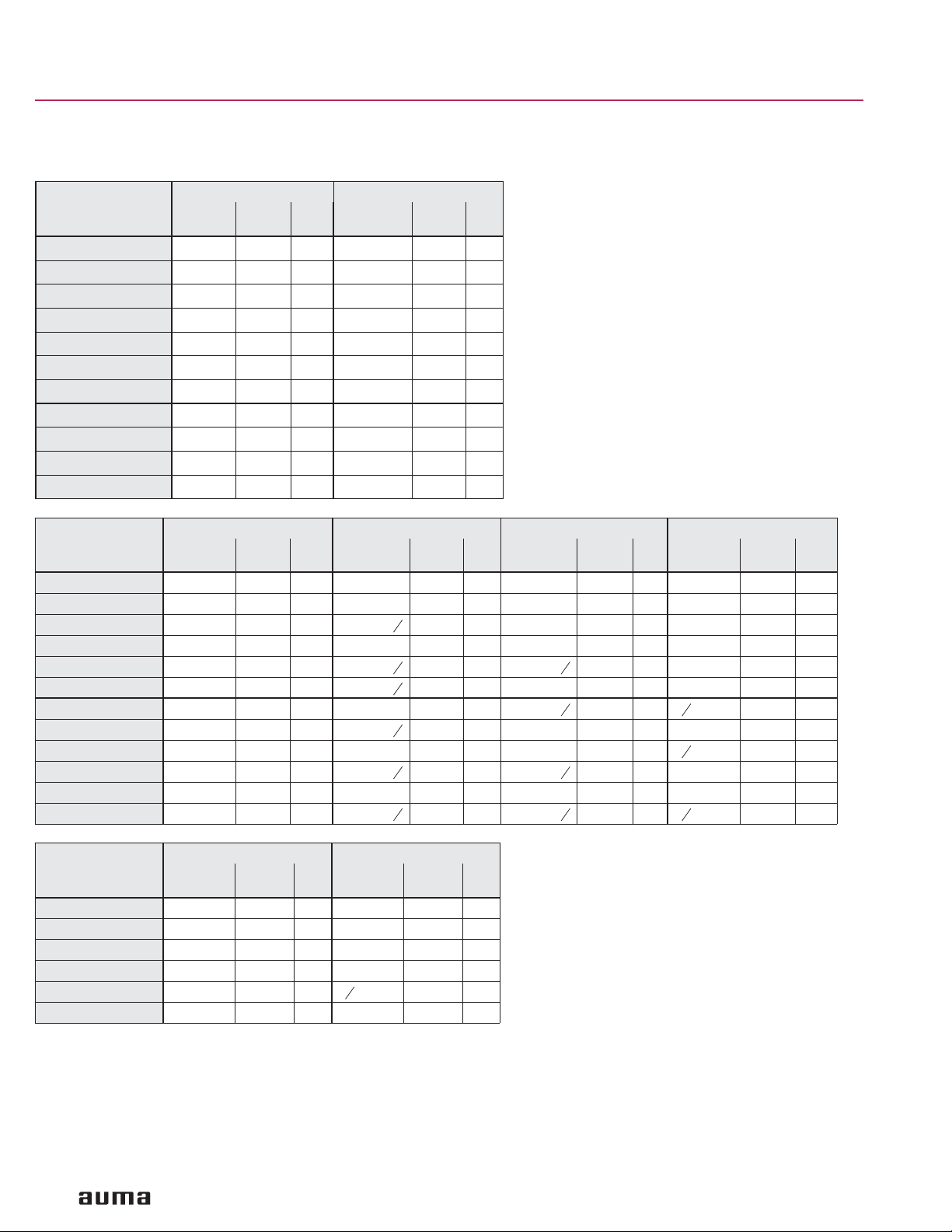
2. Technical data
Features and functions
Version Standard: clockwise rotation RR, counterclockwise rotation LL, option: RL or LR
Housing material Standard: cast iron (GJL-250), Option: spheroidal cast iron (GJS-400-15)
Self-locking The gearboxes are self-locking when at stand-still under normal service conditions; strong
Output torques
End stops Positive for both end positions by traveling nut, sensitive adjustment
Strength of end stop Guaranteed strength of end stop (in ft lbs.) for input side operation
Swing angle
GS 50.3 – GS 125.3
Swing angle
GS 160.3 – GS 250.3
Mechanical position indicator Standard: Pointer cover for continuous position indication
Input shaft Cylindrical with parallel key according to DIN 6885.1
Operation
Motor operation With electric multi-turn actuator, directly or through primary reduction gearing VZ/GZ
Type of duty According to actuator
Manual operation
1) With worm wheel made of spheroidal cast iron
2) Requires worm wheel made of bronze
3) Special sizing is required
4) For gas applications with sealed pointer cover, an air vent in the pointer cover or venting grooves in the valve mounting flange must be provided
5) Handwheel sizes shown reflect general industrial selection criteria. For information on gearbox/handwheel selection in accordance with AWWA Standard C504, please
refer to separate selection list/chart.
5)
vibrations may cancel the self-locking effect. While in motion, safe breaking is not guaranteed. If
this is required, a separate brake must be used.
Type Output torques
100 % 140 % 175 %
max. ft lbs. max. ft lbs. max. ft lbs. max. ft lbs. max. ft lbs.
GS 50.3
GS 63.3
GS 80.3
GS 100.3
GS 125.3
GS 160.3
GS 200.3
GS 250.3
Type
Reduction gearing – – – VZ 2.3 VZ 3.3 VZ 4.3 VZ 2.3 VZ 3.3 VZ 4.3
ft lbs. 185 330 330 370 185 370 185
Type
Reduction gearing GZ 160.3 GZ 200.3 GZ 250.3
Reduction ratio 4:1 8:1 4:1 8:1 16:1 4:1 8:1 16:1
ft lbs. 370 330 370 370
184 258 – 369 92
369 516 – 738 184
738 1,033 – 1,475 369
1,475 2,065 – 2,950 738
2,950 4,130 – 5,900 1,475
5,900 8,298 10,326 – 2,950
11,801 16,595 20,652 – 5,900
23,602 32,822 41,303 – 16,000
GS 50.3 GS 63.3 GS 80.3 GS 100.3 GS 125.3
GS 160.3 GS 200.3 GS 250.3
1)
200 %
1)
Modulating torque
2)
Standard: Fixed swing angle up to max. 100°; set in the factory to 92° unless ordered otherwise.
Options: Adjustable in steps of:
10°– 35°, 35° – 60°, 60° – 80°, 80° – 100°, 100° – 125°, 125° – 150°,
150° – 170°, 170° – 190°
For version with worm wheel made of bronze: swing angle > 190°,
Multi-turn version without end stops, version GSD
3)
Standard: Adjustable 80° – 100°; set in the factory to 92° unless ordered otherwise.
Options: Adjustable in steps of: 20° – 40°, 40° – 60°, 60° – 80°,
‘ Multi-turn version without end stops, version GSD
For version with worm wheel made of bronze: swing angle
3)
Options: Sealed pointer cover for horizontal outdoor installation
> 100°,
4)
Protection cover for buried service instead of pointer cover
Flanges for mounting of actuator, refer also to separate technical data sheets.
Via handwheel, directly or through primary reduction gearing VZ/GZ
Available handwheel diameters, selection according to the max. output torque:
Type
Reduction gearing – – – – VZ 2.3 VZ 3.3 VZ 4.3 – VZ 2.3 VZ 3.3 VZ 4.3
Handwheel Ø
mm
Type
Reduction gearing – GZ 160.3 – GZ 200.3 – GZ 250.3
Handwheel Ø
mm
GS 50.3 GS 63.3 GS 80.3 GS 100.3 GS 125.3
160
200
250
630
800
250
315
GS 160.3 GS 200.3 GS 250.3
400 315 – 500
315
400
400
500
315
315
400
630
250
400
315
400 315 – 800
500
630
800
400
500
400
500
500
630
315
400
400
25.4 mm correspond to 1 inch
4
Page 5

Operation instructions Worm gearboxes GS 50.3 – GS 250.3
Primary reduction gearing
Primary reduction gearing Planetary gear with various reduction ratios for reducing the input torques
Valve attachment
Valve attachment Dimensions according to SP 101
Standard: GS 50.3 – GS 125.3: without spigot
Options: GS 50.3 – GS 125.3: with spigot
Splined coupling for connection
Standard: without bore or pilot bore from GS 160.3
to the valve shaft
Options: Machined with bore and keyway, square bore or bore with two-flats
Service conditions
Enclosure protection according
to EN 60 529
6)
Standard: IP 68-3, dust and water tight up to max. 3 m head of water
Options
Corrosion protection Standard: KN Suitable for installation in industrial units, in water or power plants
Options: KS Suitable for installation in occasionally or permanently aggressive
Paint Standard: GS 50.3 – GS 125.3: Two-component iron-mica combination
Color Standard: Grey (DB 702, similar to RAL 9007)
Option: Other colors on request
Ambient temperature Standard: – 20 °F to + 175 °F/ – 25 °C to + 80 °C
Options: – 40 °F to + 140 °F/ – 40 °C to + 60 °C (low temperature), version L
Lifetime Open-close duty: The lifetime is based on a load profile typical for part-turn valves
GS 160.3 – GS 250.3: without spigot
GS 160.3 – GS 250.3: with spigot
Worm gearbox can be repositioned 4 x 90° on coupling
7)
: IP 68-6, dust and water tight up to max. 6 m head of water
IP 68-10, dust and water tight up to max. 10 m head of water
IP 68-20, dust and water tight up to max. 20 m head of water
with a low pollutant concentration
atmosphere with a moderate pollutant concentration
(e.g. in wastewater treatment plants, chemical industry)
KX Suitable for installation in extremely aggressive atmosphere
with high humidity and high pollutant concentration
GS 160.3 – GS 250.3: Two-component iron-mica combination
– 75 °F to + 140 °F/ – 60 °C to + 60 °C (extreme low temperature), version EL
+ 32 °F to + 250 °F/ – 0 °C to + 120 °C (high temperature), version H
Type Operating cycles (OPEN - CLOSE - OPEN)
100 % 140 % 175 %
GS 50.3 15,000 5,000 – 1,000
GS 63.3 15,000 5,000 – 1,000
GS 80.3 15,000 5,000 – 1,000
GS 100.3 15,000 5,000 – 1,000
GS 125.3 15,000 5,000 – 1,000
GS 160.3 15,000 5,000 1,000 –
GS 200.3 15,000 5,000 1,000 –
GS 250.3 10,000 3000 750 –
Modulating duty: min. 2.5 million operations
6) Refer to section enclosure protection IP 68
7) Not available for GS 50.3
8) With worm wheel made of spheroidal cast iron
9) The lifetime for modulating duty depends on the load and the number of starts. A high starting frequency will rarely improve the modulating accuracy. To reach the
longest possible maintenance and fault-free operation time, the number of starts per hour chosen should be as low as permissible for the process
for swivel movements of 90° (max. 100°)
and a maximum output torque of
8)
8)
200 %
9)
5
Page 6

Worm gearboxes GS 50.3 – GS 250.3 Operation instructions
Accessories
Valve position indicators Valve position indicator WSG for the signalization of intermediate and end positions for precise
Limit switching Limit switching WSH for manually operated valves. For the signalization of intermediate and
Further information
Reference documents Product description Worm gearboxes GS 50.3 – GS 250.3 /GS 315 – GS 500
Lever gearboxes See separate documents
and low-backlash feedback for swing angles ranging from 82° – 98°
(refer to separate data sheet)
Valve position indicator WGD for signalization of intermediate and end positions for swing
angles
> 180° (refer to separate data sheet)
end positions (refer to separate data sheet)
Dimension sheets GS 50.3 – GS 125.3, GS 160.3 – GS 250.3
Technical data GS 50.3 – GS 125.3, GS 160.3 – GS 250.3
Technical data SA, SAR, WSG, WGD, WSH
6
Page 7
Operation instructions Worm gearboxes GS 50.3 – GS 250.3
3. Transport, storage and packaging
3.1 Transport
3.2 Storage
3.3 Packaging Our products are protected by special packaging for the transport ex works. The
.
Transport to place of installation in sturdy packing.
.
If mounted together with actuator:
Attach ropes or hooks for the purpose of lifting by hoist only to the gearbox and
not to the actuator.
.
If eyebolts are supplied with the gearbox, they should be used to lift the gearbox
only and not the valve
.
Store in well-ventilated, dry room.
.
Protect against floor dampness by storage on a shelf or on a
wooden pallet.
.
Cover to protect against dust and dirt.
.
Apply suitable corrosion protection agent to bare surfaces.
In case worm gearboxes are to be stored for a long period
(more than 6 months), the following points must be observed additionally:
.
Prior to storage: Protect bare surfaces, in particular the output drive parts and
mounting surface, with long-term corrosion protection agent.
.
Check for corrosion approximately every 6 months. If first signs of corrosion
show, apply new corrosion protection.
packaging consists of environmentally friendly materials which can easily be
separated and recycled.
For the disposal of the packaging material, we recommend recycling and collection
centers.
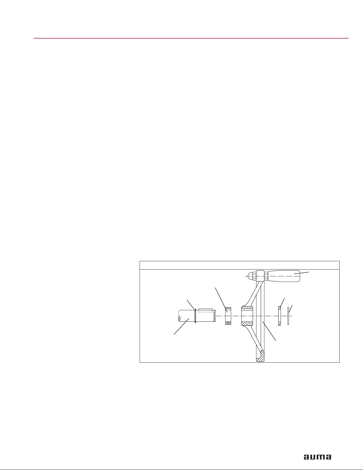
4. Fitting the handwheel For worm gearboxes designed for manual operation the handwheel may be
supplied separately. Fitting is done on site according to figure A.
Figure A: Handwheel
Ball handle
(option)
Circlip
Worm shaft
gearbox
Spacer
(may be required)
Spacer
(may be required)
Circlip
Handwheel
7
Page 8
Worm gearboxes GS 50.3 – GS 250.3 Operation instructions
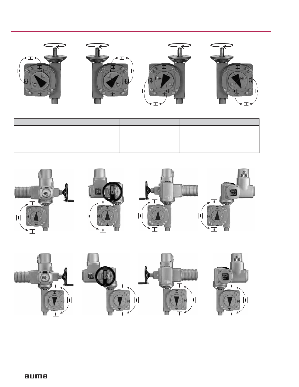
5. Mounting positions of the different versions
RR LL RL LR
Description of the 4 versions (viewed at the pointer cover):
Code Direction of rotation at input shaft Position of worm shaft Direction of rotation at output drive
RR
LL
RL
LR
clockwise
clockwise
clockwise
clockwise
Right side
Left side
Right side
Left side
Mounting positions of AUMA multi-turn actuator with AUMA worm gearbox (please indicate when ordering)
GS versions RR / RL
clockwise
counterclockwise
counterclockwise
clockwise
RR
RL
RR
RL
A
B
RR
RL
C
RR
RL
D
GS versions LL / LR
LL
LR
A
B C
LL
LR
LL
LR
D
LL
LR
Mounting positions can easily be changed at a later date.
Limitation: For SA/SAR 14.1/14.5 with GS 125.3, mounting position “C” in version RR/RL and “A” in version LL/LR is
only possible for a handwheel diameter up to 12.4 ”.
Up to size GS 125.3, the actuator-gearbox combination is delivered in the ordered mounting position. For packing
reasons, actuator and gearbox is delivered separately from size GS 160.3.
8
Page 9
Operation instructions Worm gearboxes GS 50.3 – GS 250.3
6. Mounting multi-turn actuators SA/SAR
When gearboxes and multi-turn actuators are supplied together, the mounting has
been done in the factory up to gearbox size GS 125.3. For sizes GS 160.3 and
larger, the mounting of gearboxes is performed as follows.
In case flange for actuator is not attached to gearbox or
reduction gearing:
.
Thoroughly degrease the mounting faces of the gearbox or reduction gearing as
well as the flange for actuator.
.
For GS 100.3 – GS 250.3:
Insert pin in the corresponding groove of the bearing cover.
.
Fit flange for actuator and fasten with bolts and lock washers.
.
Fasten bolts crosswise with a torque according to table 2.
Figure B: Mounting multi-turn actuator to worm gearbox
Flange for actuator
Bearing flange
Flange for actuator
Primary
reduction
gearing
Bearing flange
Mounting the multi-turn actuator:
.
Thoroughly degrease the faces of the flange for actuator at the gearbox or
reduction gearing as well as the actuator’s bearing flange.
.
Place the multi-turn actuator on the worm gearbox or reduction gearing. The
multi-turn actuator can be mounted on the valve at every 90°
(see page 8, mounting positions).
.
Ensure that the spigot mates uniformly in the recess and that the mounting faces
are in complete contact.
.
Fasten actuator with bolts and lock washers (see table 1) at the flange of the
worm gearbox.
.
Fasten bolts crosswise with a torque according to table 2.
Do not attach ropes or hooks for the purpose of lifting the actuator
by hoist to the handwheel. If multi-turn actuator is mounted on
gearbox, attach ropes or hooks for the purpose of lifting by hoist
to gearbox and not to multi-turn actuator.
9
Page 10
Worm gearboxes GS 50.3 – GS 250.3 Operation instructions
Table 1: Bolts for mounting AUMA actuators to worm gearboxes/ primary reduction gearing
(strength class min. 8.8)
Worm gearbox/
primary
reduction gearing
GS 50.3
GS 63.3
GS 80.3
GS 100.3
GS 100.3/VZ
GS 125.3
GS 125.3/VZ
GS 160.3
GS 160.3/GZ
GS 200.3
GS 200.3/GZ
SA(R) 07.1-FA10 SA(R) 07.5-FA10
Bolt
(UNC)
Lock
washer
Qty.
Bolt
(UNC)
washer
3/8-16x1 3/8 4
3/8-16x1 3/8 4
3/8-16x1 3/8 4
3/8-16x1 3/8 4
3/8-16x1 3/8 4
3/8-16x1 3/8 4
3/8-16x1 3/8 4
3/8-16x1 3/8 4
3/8-16x1 3/8 4
3/8-16x1 3/8 4
3/8-16x1 3/8 4
Lock
Qty.
Worm gearbox/
primary
reduction gearing
GS 63.3
GS 80.3
GS 100.3
GS 100.3/VZ
GS 125.3
GS 125.3/VZ
GS 160.3
GS 160.3/GZ
GS 200.3
GS 200.3/GZ
GS 250.3
GS 250.3/GZ
Worm gearbox/
primary
reduction gearing
GS 160.3
GS 160.3/GZ
GS 200.3
GS 200.3/GZ
GS 250.3
GS 250.3/GZ
SA(R) 10.1-FA10 SA(R) 14.1-FA14 SA(R) 14.5-FA14 SA(R) 16.1-FA16
Bolt
(UNC)
Lock
washer
Qty.
Bolt
(UNC)
Lock
washer
Qty.
Bolt
(UNC)
Lock
washer
Qty.
Bolt
(UNC)
washer
3/8-16x1 3/8 4
3/8-16x1 3/8 4
3/8-16x1 3/8 4
5/8-11x1
1
2
5/8 4
3/8-16x1 3/8 4
3/8-16x1 3/8 4
3/8-16x1 3/8 4
3/8-16x1 3/8 4
3/8-16x1 3/8 4
5/8-11x1
5/8-11x1
5/8-11x1
5/8-11x1
5/8-11x1
1
2
1
2
1
2
1
2
1
2
5/8 4
5/8 4
5/8 4
5/8 4
5/8 4
5/8-11x1
5/8-11x1
5/8-11x1
5/8-11x1
1
2
1
2
1
2
1
2
5/8 4
5/8 4
5/8 4
5/8 4
3
-10x2
4
3
-10x2
4
3
-10x2
4
SA(R) 25.1-FA25 SA(R) 30.1-FA30
Bolt
(UNC)
Lock
washer
Qty.
Bolt
(UNC)
Lock
washer
Qty.
5/8-11x2 5/8 8
3
5/8-11x2 5/8 8
-10x2
4
3/4 8
Lock
3/4 4
3/4 4
3/4 4
Qty.
10
Page 11

Operation instructions Worm gearboxes GS 50.3 – GS 250.3
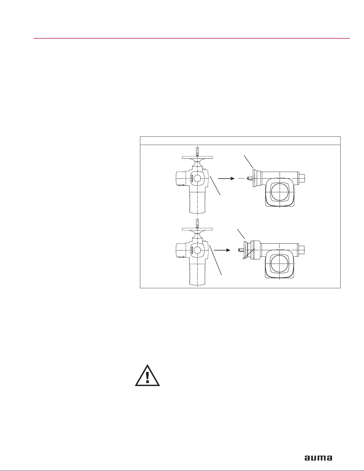
7. Mounting to valve AUMA worm gearboxes GS and primary reduction gearings VZ/GZ can be
operated in any mounting position.
.
For butterfly valves, the recommended mounting position is end position
CLOSED
(Prior to mounting, bring the gearbox to the mechanical end stop CLOSED by
turning the handwheel clockwise).
.
For ball valves, the recommended mounting position is end position OPEN
(Prior to mounting, bring the gearbox to the mechanical end stop OPEN by
turning the handwheel counterclockwise).
.
Alternatively, the limit stop housing can be turned up to the end position of the
respective valve.
.
Thoroughly degrease mounting faces of gearbox and valve.
.
Place coupling sleeve onto valve shaft and secure (refer to figure C, detail A or B),
ensure that dimensions X, Y, and Z are observed (refer to table 2).
.
Apply non-acidic grease at splines of coupling.
.
Mount gearbox on valve. Ensure that the spigot (if provided) mates uniformly in the
recess and that the mounting faces are in complete contact.
.
Fasten gearbox with bolts (quality min. 8.8) and lock washers.
.
Fasten bolts crosswise with a torque according to table 2.
Figure C
A
B
Coupling
Grub screw
X
Valve
Table 2: Standard dry fastening torques for bolts
Gearbox Dimensions Bolts Strength class
Flange type X
GS 50.3-FA10
GS 63.3-FA10
GS 63.3-FA12
GS 80.3-FA14
GS 100.3-FA14
GS 100.3-FA16
GS 125.3-FA16
GS 125.3-FA25
GS 160.3-FA25
GS 160.3-FA30
GS 200.3-FA30
GS 200.3-FA35
GS 250.3-FA35
GS 250.3-FA40
Y max Z max Qty. x threads
max
14 5 61 4 x
718 73 4 x
10 13 76 4 x
23 5 88 4 x
22 13 123 4 x
22 8 123 4 x
17 35 126 4 x
17 27 126 8 x
15 11 130 8 x
30 0 140 8 x
19 19 160 8 x
44 0 190 8 x 1 - 8 590
8 8 220 8 x 1 - 8 590
13 0 230 8 x 1
(UNC)
Z
Y
Fastening torque T
3
- 16 33
8
3
- 16 33
8
1
- 13 78
2
5
- 11 155
8
5
- 11 155
8
3
- 10 257
4
3
- 10 257
4
5
- 11 155
8
5
- 11 155
8
3
- 10 255
4
3
- 10 255
4
1
- 7 1,200
4
Grade 5
[Ft lbs.]
A
Note:
Experience showed that it is very difficult to fasten bolts or nuts of 1-8 UNC or
larger with the defined torques. The worm gearbox may be moved radially against
the valve flange by accident.
To improve adhesion between valve and gearbox, we recommend to apply
Loctite 243 (or similar products) on mounting faces.
11
Page 12

Worm gearboxes GS 50.3 – GS 250.3 Operation instructions
0
8. Setting the end stops for manual operation
If worm gearboxes GS are supplied on a valve the end stops are
already set by the valve manufacturer.
8.1 Worm gearboxes on butterfly valves
Setting end position CLOSED
Tabl e 3
Gearbox End stops fas-
GS 50.3
GS 63.3
GS 80.3
GS 100.3
GS 125.3
GS 160.3
GS 200.3
GS 250.3
Conversion factor: 1 Nm corresponds to 0.74 ft lbs.
.
Remove all bolts (03) at limit stop housing (figures D, E).
.
Turn valve manually to end position CLOSED.
.
In case limit stop housing (10) has not yet rotated, turn it clockwise up to the
stop.
.
If the holes of limit stop housing (10) do not align with the threads of the housing
(1), take off the limit stop housing (10) and replace it in the required position.
.
Fasten bolts (03) with lock washers (04).
.
Fasten bolts crosswise with a torque according to table 3.
Material Protective cap
tened with
bolts (03)
M 8 A2-80 24
M 8 A2-80 24
M 8 A2-80 24
M 12 A2-80 82
M 12 A2-80 82
M 10 A2-80 M 6 A2-80 48
M 12 A2-80 M 6 A2-80 82
M 16 A2-80 M 6 A2-80 200
Figure D: End stop up to GS 125.3
fastened with
bolts (054)
Figure E: End stop from GS 160.3
Material Fastening torque
[Nm]
T
A
03/04
10
.
If the position of the pointer cover does not correspond to the symbol CLOSED,
slightly loosen the screws of the pointer cover. Turn the pointer cover to the
CLOSED symbol and fasten the screws again.
Setting end position OPEN The end stop need not be set since the required swing angle has been set in the
factory.
If the swing angle does not match, refer to section 10.
1
03/04
1
1
12
Page 13

Operation instructions Worm gearboxes GS 50.3 – GS 250.3
8.2 Worm gearboxes on ball valves
In case end stops require adjustment, set end position OPEN first.
If the exact end position of the valve cannot be seen through a
position marking at the valve shaft, the setting may have to be
done with the valve removed.
Setting end position OPEN
Setting end position
CLOSED
9. Setting the end stops with mounted multi-turn electric actuator
.
Remove all bolts (03) at limit stop housing (10) (figures D, E).
.
Turn valve manually to end position OPEN.
.
In case limit stop housing (10) has not yet rotated, turn it counterclockwise up to
the stop.
.
If the holes of limit stop housing (10) do not align with the threads of the housing
(1), take off the limit stop housing (10) and replace it in the required position.
.
Fasten bolts crosswise with a torque according to table 3.
.
If the position of the pointer cover does not correspond to the symbol OPEN,
slightly loosen the screws of the pointer cover. Turn the pointer cover to the
OPEN symbol and fasten the screws again.
The end stop need not be set since the required swing angle has been set in the
factory.
If the swing angle does not match, refer to section 10.
.
If worm gearboxes GS and multi-turn actuators are supplied on a
valve, the end stops as well as limit and torque switching should
already have been set by the valve manufacturer.
.
If the limit and torque switching have not yet been set, they have
to be set according to the operation instructions SA/SAR and the
specifications of the valve manufacturer.
.
The valve manufacturer states whether the valve should be limit
or torque seated.
9.1 Worm gearboxes on butterfly valves
Setting end position CLOSED.Remove all bolts (03) at limit stop housing (figures D, E).
.
Determine the overrun of the multi-turn actuator for both directions, i. e. how much
does the valve move after the motor has been switched off?
.
Change actuator to manual drive and move the valve manually to end position
CLOSED.
.
In case limit stop housing (10) has not yet rotated, turn it clockwise up to the
stop.
.
Turn limit stop housing (10) back counterclockwise by ½ turn. This ensures that
the mechanical end stop is not reached in electric operation and thus the valve
can close tightly, provided that torque seating has been specified.
.
If the fixing holes of limit stop housing (10) do not align with the threads of the
housing (1), take off the limit stop housing (10) and replace it in required
position.
.
Fasten bolts (03) with lock washers (04).
.
Fasten bolts crosswise with a torque according to table 3.
.
If the position of the pointer cover does not correspond to the symbol CLOSED,
slightly loosen the screws of the pointer cover. Turn the pointer cover to the
CLOSED symbol and fasten the screws again.
13
Page 14

Worm gearboxes GS 50.3 – GS 250.3 Operation instructions
0
0
Limit seating in end position CLOSED
.
Turn back the valve from the end position by an amount equal to the overrun.
.
Set limit switching according to the operation instructions SA/SAR.
.
Check torque switching for end position CLOSED according to the operation
instructions SA/SAR, and, if necessary, set to the required value.
Torque seating in end position CLOSED
.
Turn handwheel counterclockwise by approx. 4 – 6 turns.
.
Set limit switching for the end position CLOSED according to the operation
instructions SA/SAR (for actuator indication).
.
Check torque switching for end position CLOSED or set to the required value.
Setting end position OPEN The end stop need not be set since the required swing angle has been set in the
factory.
.
Move gearbox to the end stop in position OPEN.
The last part of the travel has to be made manually.
.
To turn the valve back manually from the end position by an amount equal to the
overrun, proceed as follows:
For actuators mounted directly:
by approx. 4 to 6 turns at the handwheel.
With mounted primary reduction gearing VZ/GZ:
by approx. 10 to 15 turns at the handwheel, according to the reduction ratio of
the primary reduction gearing.
.
Set limit switching in actuator for the end position OPEN according to the
operation instructions SA/SAR.
If the swing angle does not match, refer to section 10.
9.2 Worm gearboxes on ball valves
.
Figure F: End stop up to GS 125.3
03/04
1
In case end stops require adjustment, set end position OPEN first.
If the exact end position of the valve cannot be seen through a
position marking at the valve shaft, the setting may have to be
done with the valve removed.
Determine overrun of the actuator for both directions, i. e. how much does the valve
move after the motor has been switched off?
1
Figure G: End stop from GS 160.3
03/04
1
1
14
Page 15

Operation instructions Worm gearboxes GS 50.3 – GS 250.3
Setting end position OPEN.Remove all bolts (03) at limit stop housing (10) (figures F, G).
Switching off in end position
OPEN
Setting end position
CLOSED
.
Change to manual drive and move the valve manually to end position OPEN.
.
In case limit stop housing (10) has not yet rotated, turn it counterclockwise up to
the stop.
.
Turn limit stop housing (10) back by ½ turn clockwise. This ensures that the
mechanical end stop is not reached in electric operation.
.
If the holes of limit stop housing (10) do not correspond to the threads of the
housing (1), take off the limit stop housing (10) and replace it in the required
position.
.
Fasten bolts (03) with lock washers (04).
.
Fasten bolts crosswise with a torque according to table 3.
.
If the position of the pointer cover does not align with the symbol OPEN, slightly
loosen the screws of the pointer cover. Turn the pointer cover to the OPEN
symbol and fasten the screws again.
.
Turn back the valve from the end position by an amount equal to the overrun.
.
Set limit switching according to the operation instructions SA/SAR.
The end stop need not be set since the required swing angle has been set in the
factory.
.
Move gearbox to the end stop in position CLOSED.
The last part of the travel has to be made manually.
.
To turn the valve back manually from the end position by an amount equal to the
overrun, proceed as follows:
For actuators mounted directly:
by approx. 4 to 6 turns at the handwheel.
With mounted primary reduction gearing VZ/GZ:
by approx. 10 to 15 turns at the handwheel, according to the reduction ratio of
the primary reduction gearing.
.
Set limit switching in actuator for the end position CLOSED according to the
operation instructions SA/SAR.
If the swing angle does not match, refer to section 10.
15
Page 16

Worm gearboxes GS 50.3 – GS 250.3 Operation instructions
10. Changing the swing angle
10.1 Changing the swing angle for sizes GS 50.3 – GS 125.3 (option)
The adjustment is made in end position OPEN.
Optional for size GS 50.3 – GS 125.3
Standard for size GS 160.3 – GS 250.3
Accuracy:
GS 50.3 – GS 125.3: 0.6°
GS 160.3 – GS 250.3: 0.11° to 0.14°
.
Unscrew protective cap (16) at limit stop housing (10) (figure H).
.
Remove roll pin (020) with appropriate tool (available from AUMA).
Increasing the swing angle
.
Turn end stop nut (15) back counterclockwise.
When turning back the end stop nut (015), make sure the roll pin
(020) can still be tapped in within the oblong hole.
.
Move valve into the desired end position.
.
Turn end stop nut (15) clockwise until it is tight up to the stop nut (7).
Reducing the swing angle
.
Move valve into the desired end position.
.
Turn end stop nut (15) clockwise until it is tight up to the stop nut (7).
The end stop nut (15) must entirely cover the roll pin (020).
Figure H: End stop up to GS 125.3
020 15 10 716 08
.
Tap in roll pin (020) with tool. If slot in end stop nut (15) does not align with the
hole in the worm shaft, turn end stop nut (15) slightly counterclockwise until it is
in alignment, then tap in roll pin.
.
Check O-ring (08) and replace, if damaged.
.
Replace protective cap (16).
.
If gearbox is mounted to a multi-turn actuator, set limit switching again for the
end position OPEN according to the operation instructions SA/SAR. Allow for
overrun.
Figure J: End stop from GS 160.3
082/083
058
03/04
34 1516
055
10 7056054
16
Page 17

Operation instructions Worm gearboxes GS 50.3 – GS 250.3
10.2 Changing the swing angle for sizes GS 160.3 – GS 250.3
.
Remove all bolts (054) and pull off protective cap (16)
(figure J).
.
Remove screw (082) with washer (058) and setting ring (34).
Increasing the swing angle
.
Turn end stop nut (15) back counterclockwise.
.
Move valve into the desired end position.
.
Turn end stop nut (15) clockwise until it is tight up to the stop nut (7).
Reducing the swing angle
.
Move valve into the desired end position.
.
Turn end stop nut (15) clockwise until it is tight up to the stop nut (7).
.
Place setting ring (34), secure with washer (058) and screw (082).
.
Check O-ring (056) and replace, if damaged.
.
Place protective cap (16), fasten bolts (054) with lock washers (055).
.
Fasten bolts crosswise with a torque according to table 3.
.
If gearbox is mounted to a multi-turn actuator, set limit switching again for the
end position OPEN according to the operation instructions SA/SAR. Allow for
overrun.
17
Page 18

Worm gearboxes GS 50.3 – GS 250.3 Operation instructions
11. Enclosure protection IP 68
Definition According to EN 60 529, the conditions for meeting the requirements of enclosure
protection IP 68 (requirements exceed those of IP 67) are to be agreed between
manufacturer and user. AUMA worm gearboxes and primary reduction gearings in
enclosure protection IP 68 meet the following requirements according to AUMA:
.
IP 68-3, submersible in water up to 3 m head of water
.
IP 68-6, submersible in water up to 6 m head of water
.
IP 68-10, submersible in water up to 10 m head of water
.
IP 68-20, submersible in water up to 20 m head of water
For size GS 50.3, only enclosure protection IP 68-3 is available.
If submersed in other media, additional measures for corrosion protection may be
necessary; please consult AUMA. Submersion in aggressive media, e.g. acids or
alkaline solutions, is not permitted.
Review Gearboxes in enclosure protection IP 68-3 were type tested in the factory.
Gearboxes in enclosure protection IP 68-6, IP 68-10 and IP 68-20 undergo a
routine testing for tightness in the factory.
Note:
.
The enclosure protection IP 68 refers to the interior of the gearboxes, but not to
the coupling compartment.
.
If the gearboxes are likely to be repeatedly submersed, a higher corrosion
protection KS or KX is required.
.
For gearboxes intended for buried service we strongly recommend to use the
higher corrosion protection KS or KX.
.
For horizontal outdoor installation of the gearboxes, a sealed pointer cover
should be used.
For gas applications with sealed pointer cover, an air vent in the pointer cover or
venting grooves in the valve mounting flange must be provided.
.
In case of permanent submersion of the gearboxes or for buried service, a
protection cover must be fitted instead of a pointer cover. This will be taken into
account in the factory if indicated on the purchase order. Subsequent exchange
of the pointer cover for the protection cover is possible.
.
Use suitable sealing material between valve flange and gearbox.
.
Water can enter into the coupling compartment along the valve shaft. This would
lead to corrosion of hub and coupling. Therefore a suitable anticorrosive (or
sticky grease) must be applied to the hub and coupling of the gearbox before
mounting.
.
With corrosion protection KX, the hub and coupling are provided with a high
quality corrosion protection as standard.
18
Page 19

Operation instructions Worm gearboxes GS 50.3 – GS 250.3
12. Maintenance
12.1 General notes After commissioning, check worm gearbox for damage to paint finish.
Do a thorough touch-up to prevent corrosion.
Original paint in small quantities can be supplied by AUMA.
AUMA worm gearboxes require only very little maintenance.
To ensure that the worm gearbox is always ready to operate,
gearboxes operated less than 10 times per year,
.
Approximately six months after commissioning and every year after check bolts
between multi-turn actuator, worm gearbox, and valve for tightness. If required,
tighten applying the torques given in table 2 (page 11).
.
Perform a test run every six months.
.
Perform a visual inspection for grease leakage on each gearbox every
2 years.
.
Carry out a detailed functional test for each gearbox every 5 years. Record the
results for future reference.
.
For gearboxes permanently exposed to ambient temperatures above
104 °F, maintenance must be performed at shorter intervals.
Seals:
Seals made of elastomeric materials are subject to ageing. The theoretical usable
lifetime of the seals made of NBR is 13.5 years from the date of manufacture.
These figures are based on an average ambient temperature of 104 °F. Seal kits
may be obtained from AUMA.
the following measures:
we recommend for
Grease:
A grease and seal change is recommended after the following operation time:
.
if operated seldom after 10 – 12 years
.
if operated frequently, after 6 – 8 years
.
in modulating duty after 4 – 6 years
.
Only original AUMA grease must be used.
.
For the grease type, refer to the name plate.
.
Lubricants should not be mixed.
Table 4: Grease quantities for worm gearboxes and primary reduction gearings
GS
Qty dm³
Weight1)g
Primary
reduction
gearing
Quantity dm³
Weight1)g
1) for ρ = approx. 900 g/dm3; conversion factor: 1 oz corresponds to 28.35 g
The removed lubricant and the cleaning agent used must be
disposed of according to the relevant regulations.
50.3 63.3 80.3 100.3 125.3 160.3 200.3 250.3
0.1 0.3 0.4 1.0 1.3 3.3 6.6 12.2
90 270 360 900 1,170 3,000 6,000 11,000
VZ GZ
2.3 3.3 4.3 160.3 200.3 250.3
4:1/8:1 16:1 4:1/8:1 16:1
0.35 0.35 0.35 1.0 1.5 2.0 2.2 2.8
320 320 320 900 1,400 1,800 2,000 2,250
19
Page 20

Worm gearboxes GS 50.3 – GS 250.3 Operation instructions
12.2 Grease change for worm gearboxes GS 50.3 – GS 125.3 and primary reduction gearing VZ 2.3 – VZ 4.3
.
For gearboxes with multi-turn actuator: Remove multi-turn actuator.
.
Remove gearbox from the valve:
During this time, the valve/pipeline must not be under pressure!
12.2.1 Worm gearboxes Refer to spare parts list GS 50.3 – GS 125.3, page 24.
Grease type, see name plate; grease quantities, see page 19, table 4.
.
Mark position of the gearbox on the valve, loosen connecting bolts to the valve
and remove the worm gearbox.
.
Remove fastening bolts with lock washers from the housing cover (518.0) and
take off housing cover.
.
Remove bolts with lock washers from the bearing cover (522.0). Lift worm wheel
carefully from the housing. For this, the worm shaft must be pulled from the
bearings and tilted slightly in the worm channel.
.
Remove old grease completely from the housing and the individual parts and
clean gear housing. For this purpose, a suitable cleaning agent should be used.
.
Clean mounting faces at housing and housing cover (518.0). Replace O-rings at
the worm wheel (010, 011) by new ones.
.
Re-insert worm wheel carefully and bring worm shaft into correct position, fasten
bearing cover (522.0) at housing with bolts and lock washers.
.
Fill with new grease.
.
Place housing cover (518.0) on housing, while ensuring the proper position of
the O-rings (010, 011) at the worm wheel. Place bolts with lock washers and
fasten them evenly crosswise.
– Thoroughly degrease mounting faces at mounting flange.
– Apply non-acidic grease at splines of coupling
– Mount worm gearbox to valve, ensure correct position,
observe mark made in previous step
– Fasten with bolts of minimum quality 8.8 using lock washers, fasten bolts
crosswise to the appropriate torque according to table 2, page 11.
.
Gearbox without primary reduction gearing: Continue with section “After
maintenance”.
.
Gearbox with reduction gearings VZ 2.3 – VZ 4.3: Perform grease change at the
reduction gearing according to the following subsection.
12.2.2 Primary reduction gearing Refer to spare parts list VZ 2.3 – VZ 4.3., page 24.
Grease type, see name plate; grease quantities, see page 19, table 4.
.
Remove bolts with lock washers from housing cover (020.0) and pull off housing
cover (020.0) with the complete input drive shaft (021.0).
.
Take off plate with internal teeth (045.0) and planet carrier (022.0) with the
planet wheels.
.
Remove old grease completely from the housing and the individual parts and
clean them. For this purpose, a suitable cleaning agent should be used.
.
Clean mounting faces at housing (019.0), housing cover (020.0) and plate with
internal teeth (045.0). Replace O-rings by new ones.
.
Insert planet carrier (022.0) with planet wheels.
.
Fill with new grease.
.
Place plate with internal teeth (045.0) and insert the input drive shaft (021.0)
completely. Screw in bolts with lock washers and fasten them evenly crosswise to
the appropriate torque according to table 2, page 11.
.
Continue with section “After maintenance”, page 22.
20
Page 21

Operation instructions Worm gearboxes GS 50.3 – GS 250.3
12.3 Grease change for worm gearboxes GS 160.3 – GS 250.3 and primary reduction gearing GZ 160.3 – GZ 250.3
.
For gearboxes with multi-turn actuator: Remove multi-turn actuator.
.
Remove gearbox from the valve:
During this time, the valve/pipeline must not be under pressure!
12.3.1 Worm gearboxes Refer to spare parts list GS 160.3 – GS 250.3, page 26.
Grease type, see name plate; grease quantities, see page 19, table 4.
Tools: Lock nut tool, can be obtained from AUMA.
.
Mark position of the gearbox on the valve, loosen connecting bolts to the valve
and remove the worm gearbox.
.
Remove bolts with lock washers from the housing cover (518.0) and take off
housing cover.
.
Remove bolts with lock washers from the bearing cover (522.0). Take off bearing
lock nut (537.0) by loosening the grub screw. Remove protective cap (536.0), pull
off snap ring from end nut (526.0). Remove end stop (523.0). Lift worm wheel
carefully from the housing. For this, the worm shaft must be pulled from the
bearings and tilted slightly in the worm channel.
Pull out worm shaft from housing in direction of the input shaft.
.
Remove old grease completely from the housing and the individual parts and
clean gear-housing. For this purpose, a suitable cleaning agent should be used.
.
Clean mounting faces at housing and housing cover (518.0). Replace O-rings at
the worm wheel (010, 011) by new ones.
.
Re-insert worm wheel carefully and bring worm shaft into correct position. Screw
in bearing lock nut (537.0) and secure with grub screw. Fasten bearing cover
(522.0) at the housing with bolts and lock nuts.
.
Fill with new grease.
.
Place housing cover (518.0) on housing, while ensuring the proper position of
the O-rings (010, 011) at the worm wheel. Place bolts with lock washers and
fasten them evenly crosswise.
– Thoroughly degrease mounting faces at mounting flange and valve.
– Apply non-acidic grease at splines of coupling.
– Mount worm gearbox to valve, ensure correct position, observe mark.
– Fasten with bolts of minimum quality 8.8 using lock washers, fasten bolts
crosswise to the appropriate torque according to table 2, page 11.
.
Gearbox without primary reduction gearing: Continue with section “After
maintenance”.
.
Gearbox with reduction gearings GZ 160.3 – GZ 250.3: Perform grease change
at the reduction gearing according to the following sections.
12.3.2 Single-stage reductions gearings GZ 160.3 – GZ 250.3 (reduction ratios 4:1 and 8:1)
Refer to spare parts list GZ 160.3 – GZ 250.3, page 28.
Grease type, see name plate; grease quantities, see page 19, table 4.
.
Remove bolts with lock washers at housing cover (002.0) and pull off housing
cover (002.0) with the input drive shaft (003.0) and the plate with internal teeth).
.
Remove screws from the plate with internal teeth and separate the plate with
internal teeth from the input drive shaft.
.
Remove old grease completely from the housing and the individual parts and
clean them.
.
For this purpose, a suitable cleaning agent should be used.
.
Clean mounting faces at housing (001.0), housing cover (002.0) and plate with
internal teeth. Replace O-rings by new ones.
.
Fill housing cover (002) with new grease.
.
Fix plate with internal teeth (006.0) with screws at housing cover.
21
Page 22

Worm gearboxes GS 50.3 – GS 250.3 Operation instructions
.
Fill housing (001.0) with remaining grease and fit the complete housing cover
with input drive shaft (003.0). Screw in bolts with lock washers and fasten them
evenly crosswise to the appropriate torque according to table 2, page 11.
.
Continue with section “After maintenance”, page 22.
12.3.3 Double-stage primary reduction gearing GZ 200.3 – GZ 250.3 (reduction ratio 16:1)
Refer to spare parts list GZ 160.3 – GZ 250.3, page 28.
Grease type, see name plate; grease quantities, see page 19, table 4.
.
Remove bolts with lock washers from housing cover (002.0) and pull off housing
cover with the complete input drive shaft (003.0).
.
Take off screws with lock washers from housing frame (010.0) and remove
housing frame with planet carrier and hollow wheel.
.
Remove screws from the plate with internal teeth and separate the plate with
internal teeth from the input drive shaft (003.0).
.
Remove screws (021) from the second stage of the plate with internal teeth and
separate it from the pinion (011.1).
.
Remove old grease completely from the housing and the individual parts and
clean them. For this purpose, a suitable cleaning agent should be used.
.
Clean mounting faces at housing (001.0), housing frame, housing cover (002.0)
and hollow wheels. Replace O-rings by new ones.
.
Fill housing (001.0) with new grease.
.
Fix second stage of the plate with internal teeth on housing frame (010.0).
.
Replace complete housing frame. Screw in bolts with lock washers and fasten
them evenly crosswise to the appropriate torque according to table 2, page 11.
.
Fill housing frame (010.0) and housing cover (002.0) with the remaining grease.
.
Fix first stage of the plate with internal teeth on the housing cover (002.0).
.
Place complete housing cover with input drive shaft onto housing frame. Screw
in bolts with lock washers and fasten them evenly crosswise to the appropriate
torque according to table 2, page 11.
12.4 After maintenance
.
If applicable, mount multi-turn actuator.
.
Reset the end stops.
.
For gearboxes with multi-turn actuator, check the setting of the limit switching
according to the operation instructions for multi-turn actuators; if required, reset.
.
Perform test run to ensure the proper function.
.
Check worm gearbox for damage to paint finish. Do a thorough touch-up to
prevent corrosion. Original paint in small quantities can be supplied by AUMA.
22
Page 23

Operation instructions Worm gearboxes GS 50.3 – GS 250.3
13. Disposal and recycling
AUMA gearboxes have an extremely long lifetime. However, they have to be
replaced at one point in time.
Our gearboxes have a modular design and may therefore easily be disassembled,
separated and sorted according to materials, i.e.:
.
various metals
.
plastics
.
greases and oils
The following generally applies:
.
Collect greases and oils during disassembly. As a rule, these substances are
hazardous to water and must not be released into the environment.
.
Send disassembled material to a sound disposal or to separate recycling center
according to materials.
.
Observe the local regulations for waste disposal.
14. Service AUMA offers extensive services such as maintenance and inspection for
gearboxes.
The AUMA service department can be reached at:
phone: 724-743-AUMA (2862)
fax: 724-743-4711
email: mailbox@auma-usa.com
www.auma-usa.com or www.auma.com.
23
Page 24

Worm gearboxes GS 50.3 – GS 250.3 Operation instructions
15. Spare parts list worm gearboxes GS 50.3 – GS 125.3 and reduction gearing VZ 2.3 – VZ 4.3
512.0
512.0
020.0
522.0
S1(009)
S1(009)
522.0
S1(017)
524.0
S1(011)
521.1
S1(012)
512.0
S1(017)
520.0
526.0
S1(009)
S1(017)
520.0
S1(010)
517.0
519.1
S1(010)
S1(034)
021.0
534.0
520.0
045.0
525.0
022.0
S1(033)
S1(033)
24
019.0
518.0
S1(073)
527.0
S1(009)
523.0
S1(076)
S1(009)
Page 25

Operation instructions Worm gearboxes GS 50.3 – GS 250.3
Note: Please state type and commission no. of the device (see name plate) when ordering spare parts. Only original
AUMA spare parts should be used. Delivered spare parts may slightly vary from the representation
in these instructions.
No. Designation Type
019.0
020.0
021.0
022.0
045.0
512.0
517.0
518.0
519.1
520.0
521.1
522.0
523.0
524.0
525.0
526.0
527.0
534.0
536.0
S1
Housing VZ Sub-assembly
Housing cover VZ Sub-assembly
Input drive shaft VZ Sub-assembly
Planet carrier VZ Sub-assembly
Plate with internal teeth VZ Sub-assembly
Flange for actuator Sub-assembly
Housing Sub-assembly
Housing cover Sub-assembly
Worm wheel Component
Worm shaft Sub-assembly
Travelling nut Component
Bearing cover Sub-assembly
Limit stop housing Sub-assembly
Pointer cover Sub-assembly
Coupling Sub-assembly
End stop nut Sub-assembly
Protection cover Sub-assembly
Input shaft Sub-assembly
Cap Sub-assembly
Seal kit Set
25
Page 26

Worm gearboxes GS 50.3 – GS 250.3 Operation instructions
16. Spare parts list worm gearboxes GS 160.3 – GS 250.3
537.0
512.0
520.0
521.1
524.0
S1(011)
518.0
S1(012)
522.0
S1(009)
538.1
526.0
517.0
S1(017)
538.0
26
513.1
S1(009)
S1(056)
S1(073)
527.0
S1(010)
523.0
519.1
536.0
S1(010)
525.0
Page 27

Operation instructions Worm gearboxes GS 50.3 – GS 250.3
Note: Please state type and commission no. of the device (see name plate) when ordering spare parts. Only original
AUMA spare parts should be used.
Delivered spare parts may slightly vary from the representation in these instructions.
No. Designation Type
512.0
513.0
517.0
518.0
519.1
520.0
521.1
522.0
523.0
524.0
525.0
526.0
527.0
536.0
538.0
538.1
S1
Flange for actuator Sub-assembly
Grub screw Component
Housing Sub-assembly
Housing cover Sub-assembly
Worm wheel Component
Worm shaft Sub-assembly
Travelling nut Component
Bearing cover Sub-assembly
Limit stop housing Sub-assembly
Pointer cover Sub-assembly
Coupling Sub-assembly
End stop nut Sub-assembly
Protection cover Sub-assembly
Cap Sub-assembly
Input shaft Sub-assembly
Input shaft Sub-assembly
Seal kit Set
27
Page 28

Worm gearboxes GS 50.3 – GS 250.3 Operation instructions
002.0
17. Spare parts list reduction gearings GZ 160.3 – GZ 250.3 (reduction ratios 4:1, 8:1 and 16:1)
GZ 200.1 – GZ 250.1
GZ 160.1 – GZ 250.1
16:1
4:1 / 8:1
S1(004)
S1(009)
001.0
S1(009)
S1(004)
001.0
003.3
006.0
S1(029)
006.0
S1(003)
S1(029)
003.0
003.3
S1(003)
S1(003)
S1(003)
003.0
S1(014)
512.0
002.0
011.1
010.0
GZ 200.1 – GZ 250.1
16:1
S1(009)
S1(004)
001.0
013.0
006.0
S1(029)
S1(003)
S1(029)
S1(014)
512.0
S1(003)
003.0
003.3
S1(014)
512.0
002.0
28
011.1
013.0
010.0
Page 29

Operation instructions Worm gearboxes GS 50.3 – GS 250.3
Note:
Please state type and commission no. of the device (see name plate) when ordering spare parts. Only original AUMA
spare parts should be used. Delivered spare parts may slightly vary from the representation in these instructions.
No. Designation
001.0
002.0
003.0
003.3
006.0
010.0
011.1
013.0
512.0
S1
Housing Sub-assembly
Housing cover Sub-assembly
Housing cover Sub-assembly
Input drive shaft Sub-assembly
Planetary gear Sub-assembly
Housing frame Sub-assembly
Pinion Sub-assembly
Planetary gear 1st stage Sub-assembly
Flange for actuator Sub-assembly
Seal kit Set
29
Page 30

Worm gearboxes GS 50.3 – GS 250.3 Operation instructions
Notes
30
Page 31

Operation instructions Worm gearboxes GS 50.3 – GS 250.3
Index
B
Bolts for mounting actuators 10
C
Changing the swing angle 16
Corrosion protection 7
D
Disposal and recycling 23
E
Enclosure protection IP 68 18
F
Fitting the handwheel 7
H
Handwheel 7
L
Lubricant 19
M
Maintenance 3,19
Manual operation 12
Motor operation 13
Mounting positions 8
Mounting the multi-turn actuators 9
Mounting to valve 11
P
Packaging 7
R
Range of application 3
S
Safety instructions 3
Service support/ Parts 23
Setting the end stop
with mounted
multi-turn actuator 13
Setting the end stops
for manual operation 12
Spare parts list
GS 50.3 - GS 125.3 24,25
GS 160.3 - GS 250.3 26,27
GZ 160.3 - GZ 250.3
(4:1/8:1/16:1) 28,29
Storage 7
T
Technical data 4
Transport 7
31
Page 32

North American Sales and Service:
US Headquarters and Factory:
AUMA Actuators, Inc.
100 Southpointe Blvd.
Canonsburg PA 15317
Tel: 724-743-AUMA (2862)
Fax: 724-743-4711
email: mailbox@auma-usa.com
www.auma-usa.com
Regional Offices:
Northeast (Maryland and New York)
Southeast (South Carolina)
Midwest (Illinois)
Midwest (Kansas)
Houston (Texas)
West Coast (Northern and Southern California)
Representatives and Distributors
Anchorage
Atlanta
Baltimore
Baton Rouge
Birmingham
Boston
Charlotte
Chicago
Cincinatti
Corpus Christi
Dallas
Denver
Detroit
Hawaii
Houston
Indianapolis
Kansas City
Los Angeles
Mexicali (Mexico)
Mexico City
Milwaukee
Minneapolis
Montana
Monterrey (Mexico)
New York
Omaha
Orlando
Philadelphia
Phoenix
Pittsburgh
Rochester
Salt Lake City
San Diego
San Francisco
San Juan
Seattle
St. Louis
Toronto
Tulsa
International Headquarters:
AUMA Riester GmbH & Co. KG
Müllheim/ Germany
www.auma.com
International Sales and Service:
South America:
Argentina
Brazil
Chile
Colombia
Peru
Venezuela
Europe:
Austria
Benelux
Czech Republic
Denmark
Finland
France
Greece
Hungary
Italy
Norway
Poland
Portugal
Russia
Spain
Sweden
Switzerland
Turkey
Ukraine
United Kingdom
Africa
Egypt
South Africa
Asia, Australia
Australia
China
Hong Kong
India
Japan
Korea
Kuwait
Oman
Qatar
Singapore
Taiwan
Thailand
UAE
For the name and phone number of the office
nearest you, call us at 724-743-2862 or visit our
website at www.auma-usa.com/saleserv.htm
2005-06-27
Y003.822/031/us/1.06
 Loading...