

Page 1
Certificate Registration No.
12 100/104 4269
Actuator controls
Operation instructions
AUMA MATIC
AM 01.1/ AM 02.1
AMExB 01.1/ AMExC 01.1
Modbus
Page 2

2
Actuator controls AUMA MATIC AM/ AMExB/ AMExC
Modbus Operation instructions
Scope of these instructions: These instructions are valid for multi-turn actuators of type ranges
SA(R) 07.1 – SA(R) 16.1 and SA(R)ExC 07.1 – SA(R)ExC 16.1 and for
part-turn actuators of type ranges SG(R) 05.1 – SG(R) 12.1 and SGExC
05.1 – SGExC 12.1 with the controls AUMA MATIC AM 01.1/ AM 02.1
or AMExB 01.1 and AMExC 01.1 and Modbus interface.
Table of contents Page
1. Safety instructions 4
1.1 Range of application 4
1.2 Commissioning (electrical connection) 4
1.3 Maintenance 4
1.4 Warnings and notes 4
2. Short description 4
3. Transport and storage 5
4. General information about Modbus 5
4.1 Basic characteristics 5
4.2 Modbus Basic functions 6
4.3 Transfer mode 6
4.4 Bus access 6
4.5 Communication 6
4.6 Protection functions 6
4.7 Modbus RTU mode 6
5. Technical data 7
6. Design AUMA MATIC Modbus 10
7. Electrical connection 11
7.1 Power supply (standard) 11
7.2 Bus connection (standard) 12
7.3 Fitting the cover 13
7.4 Remote position transmitter 14
7.5 AUMA MATIC on wall bracket 14
7.6 Test run 14
7.7 Mains and bus connection for Ex-version with plug/ socket connector / terminal board (KP) 15
7.8 Mains and bus connection for Ex-version with plug-in terminal connection (KES) 17
7.9 Redundant bus connection 18
7.10 Bus cables 19
7.11 Setting the Modbus interface 20
7.12 Setting the communication parameter 21
7.13 Setting parameter seating mode in end position CLOSED, parity bits and number of stop bits 21
7.14 Setting the Modbus address: 21
7.15 Setting the baud rate 22
8. Commissioning with controls 23
8.1 Introduction 23
8.2 Overview over the Modbus functions for data transmission 23
8.3 Modbus function and corresponding offset addresses of the AUMA MATIC 23
9. Input data 24
9.1 Reading the actuator signals from the actuator using register functions 24
9.2 Description of the input data 26
9.3 Reading the feedback signals from the actuator using status functions 30
10. Process representation output 32
10.1 Transmitting operation commands to or reading out from the actuator using register functions 32
10.2 Description of the output data 32
10.3 Transmission of operation commands to the actuator using coil functions 33
Page 3

3
Actuator controls AUMA MATIC AM/ AMExB/ AMExC
Operation instructions Modbus
Page
11. Operation parameters of the actuator 34
12. Description of actuator functions 41
12.1 Operation commands for OPEN/ CLOSE operation 41
12.2 Positioner 41
12.3 Stepping mode 42
13. Failure function 43
14. Description Modbus interface 44
14.1 Indication during system start-up: 44
14.1.1 Indications of operation LEDs 7 to 0 44
14.1.2 System displays LEDs L1 to L4 45
14.2 Customer inputs assignment of the Modbus interface (option) 45
14.3 Modbus connection assignment 46
14.4 Assignment positioner connections 46
14.5 Checking/ setting the switches on the logic board 47
15. Troubleshooting and corrective actions 48
15.1 Actuator can not be controlled via Modbus 48
15.2 Position feedback does not function 51
15.3 Actuator is not switched off by the limit switch in direction CLOSE 51
15.4 Actuator stops immediately after having started 51
15.5 Actuator does not signalise reference operation, connection failure position transmitter or
signal interruption position transmitter 51
15.6 Measuring the Modbus signals using an oscilloscope 51
16. Appendix A Standard wiring diagram 52
16.1 Legend for standard wiring diagram 53
16.2 Additional information to the wiring diagram legend 53
17. Appendix B Proposed external wiring diagram 54
18. Appendix C Literature references 57
19. Appendix D Connecting the cable shield for AUMA MATIC AMExB/ AMExC 01.1 57
Index 59
Addresses of AUMA offices and representatives 60
Page 4
1. Safety instructions
1.1 Range of application AUMA actuators are designed for the operation of industrial valves,
e.g. globe valves, gate valves, butterfly valves and ball valves.
For other applications, please consult us. The manufacturer is not liable for
any possible damage resulting from use in other than the designated appli
cations. Such risk lies entirely with the user.
Observance of these operation instructions is considered as part of the
controls’ designated use.
1.2 Commissioning
(electrical connection)
During electrical operation, certain parts inevitably carry lethal voltages.
Work on the electrical system or equipment must only be carried out by a
skilled electrician himself or by specially instructed personnel under the
control and supervision of such an electrician and in accordance with the
applicable electrical engineering rules.
1.3 Maintenance The maintenance instructions must be strictly observed, otherwise a safe
operation of the multi-turn actuator/ the controls is no longer guaranteed.
1.4 Warnings and notes Non-observance of the warnings and notes may lead to serious injuries or
damage. Qualified personnel must be thoroughly familiar with all warnings
and notes in these operation instructions.
Correct transport, proper storage, mounting and installation, as well as
careful commissioning are essential to ensure a trouble-free and safe operation.
The following references draw special attention to safety-relevant procedures in these operation instructions. Each is marked by the appropriate
pictograph.
This pictograph means: Note!
“Note” marks activities or procedures which have major influence on the
correct operation. Non-observance of these notes may lead to consequential damage.
This pictograph means: Electrostatically endangered parts!
If this pictograph is attached to a printed circuit board, it contains parts
which may be damaged or destroyed by electrostatic discharges. If the
boards need to be touched during setting, measurement, or for exchange, it
must be assured that immediately before a discharge through contact with
an earthed metallic surface (e.g. the housing) has taken place.
This pictograph means: Warning!
“Warning” marks activities or procedures which, if not carried out correctly,
can affect the safety of persons or material.
2. Short description AUMA actuators have a modular design. Motor and gearing are mounted in
a common housing.
The actuators are driven by an electric motor and controlled with the electronic controls AUMA MATIC Modbus. The electronic controls are included
in the scope of delivery.
4
Actuator controls AUMA MATIC AM/ AMExB/ AMExC
Modbus Operation instructions
Page 5

3. Transport and storage
.
Transport to place of installation in sturdy packing.
.
Do not attach ropes or hooks to the handwheel for the purpose of lifting by
hoist.
.
Store in well-ventilated, dry room.
.
Protect against floor dampness by storage on a shelf or on a wooden
pallet.
.
Cover to protect against dust and dirt.
.
Apply suitable corrosion protection agent to bright surfaces.
4. General information about Modbus
For the exchange of information among automation systems and between
automation systems and the connected decentral field devices, serial
fieldbuses are mainly used today as the communication system. Thousands
of applications have proved impressively that cost savings of up to 40 % in
wiring, commissioning, and maintenance are achieved by using fieldbus
technology. Just two wires are needed to transmit all relevant information for
the field devices, such as input and output signals, parameters, and diagnostics data. While in the past the fieldbuses used were often manufacturer
specific and incompatible with other bus systems, the systems employed
today are almost exclusively open and standardized. This means that the
user is independent of individual suppliers and can choose the best product
at the most competitive price.
Modbus is an open international fieldbus system which is also used
successfully throughout the world. The application range includes automation in the areas of manufacturing, processing, and building.
These operation instructions cannot provide a general introduction into
Modbus. For this, please refer to the literature references in appendix C
(page 57).
4.1 Basic characteristics Modbus defines the functional features of a serial fieldbus system with
which distributed digital automation devices can be interconnected. Modbus
distinguishes between master and slave devices.
Master devices control the data traffic on the Bus. A master is allowed to
send messages without an external request.
Slave devices such as AUMA Modbus actuators are peripheral devices.
Typical slave devices are input/ output devices, valves, actuators, and
measuring transmitters. They do not have bus access, i.e. they may only ,at
the request of a master, transmit messages to that master.
5
Actuator controls AUMA MATIC AM/ AMExB/ AMExC
Operation instructions Modbus
Page 6

4.2 Modbus Basic functions Modbus uses a master-slave technique in which only the master can initiate
a transaction. The slaves respond by supplying the requested data in a reply
or by executing the action requested in the query.
The Modbus telegram from the master contains the slave address, a func
tion code defining the requested action, a data field, and a CRC field. The
Modbus slaves’ response message contains fields confirming the requested
action and possibly the requested data and also a CRC field.
If an error occurs during reception of the telegram or the slave is unable to
perform the requested action, the slave will generate an error telegram and
send it as response to the master.
4.3 Transfer mode
.
RS-485 twisted pair cable or fibre optic cable.
.
AUMA actuators support baud rates up to 38.4 kBit/s
4.4 Bus access
.
Master-slave technique.
.
Mono-master system.
.
Master and slave devices: max. 127 devices at one bus
(the AUMA MATIC supports slave addresses from 1 to 127), without
repeater max. 32 devices.
4.5 Communication
.
Master-slave data exchange via query-response cycle (Polling procedure).
.
Modbus RTU protocol.
4.6 Protection functions
.
Parity check for each telegram byte
.
CRC check for each telegram
.
Watchdog for AUMA actuators with adjustable failure behaviour.
.
Query-response cycle monitoring with configurable timer interval at the
master.
4.7 Modbus RTU mode Data format for a byte.
Coding system:
.
8 bit binary, hexadecimal 0-9, A-F
.
2 hexadecimal characters contained in each 8 bit field of the telegram
Bits per byte:
.
1 start bit
.
8 data bits; least significant bit sent first
.
1 bit for even/ odd parity, no bit for no parity
.
1 stop bit if parity is used, 2 stop bits if no parity is used.
6
Actuator controls AUMA MATIC AM/ AMExB/ AMExC
Modbus Operation instructions
Page 7
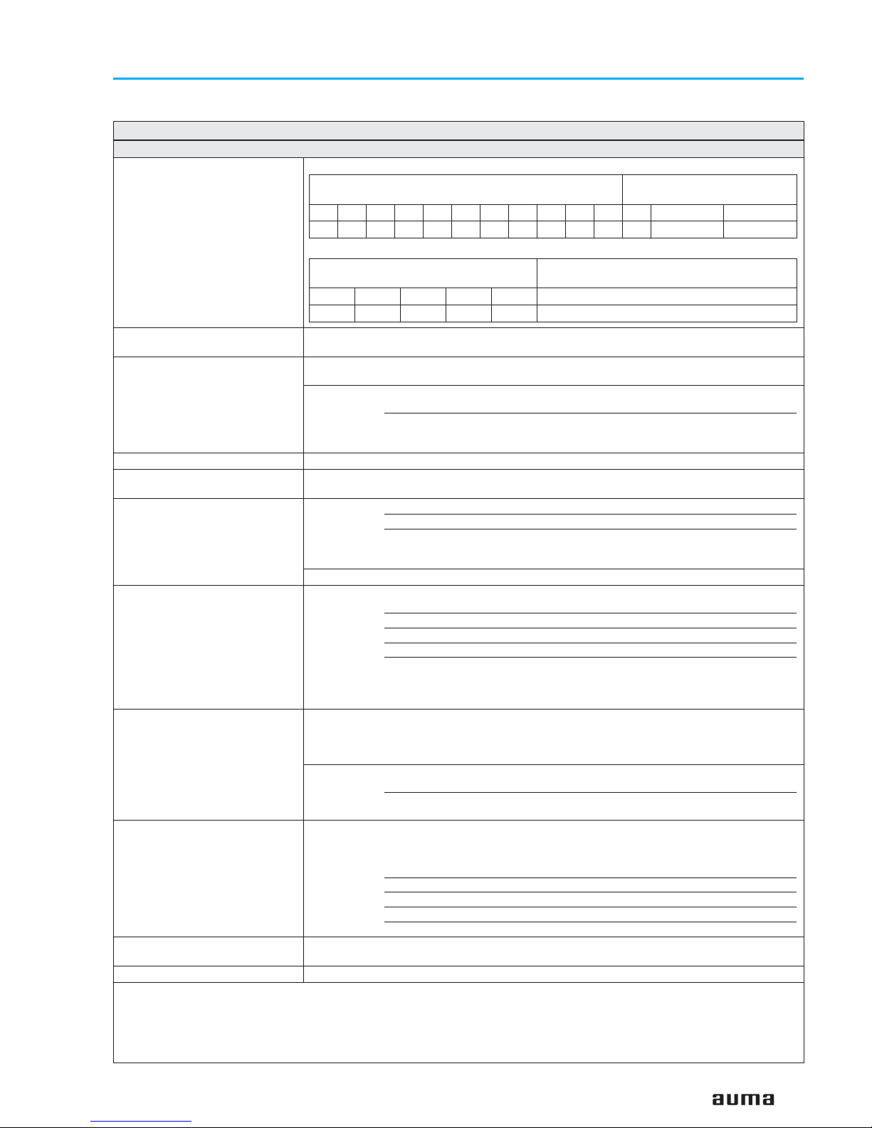
5. Technical data
7
Actuator controls AUMA MATIC AM/ AMExB/ AMExC
Operation instructions Modbus
Features and functions
Power supply Standard voltages:
Special voltages:
External supply of the electronics
(option)
24 V DC + 20 % / – 15 %,
Current consumption: Basic version approx. 200 mA, with options up to 500 mA
Switchgear Standard: Reversing contactors
2)
(mechanically and electrically interlocked)
for motor power up to 1.5 kW
Options: Reversing contactors
2)
(mechanically and electrically interlocked)
for motor power up to 7.5 kW
Thyristor unit3)(recommended for modulating actuators)
for motor power up to 1.5 kW, 500 V AC, with internal fuses
for motor power up to 5.5 kW, 500 V AC, external fuses required
Control and output signals via Modbus interface
Modbus interface with additional
inputs (option)
Modbus interface with 4 free 24 V DC inputs and 2 free 0/4 – 20 mA inputs. Signal
transmission vial fieldbus interface.
Local controls Standard: Selector switch LOCAL – OFF – REMOTE (lockable in all three positions)
Push buttons OPEN – STOP – CLOSE
3 indication light:
End position CLOSED (yellow), collective fault signal (red),
End position OPEN (green)
Option: Protection cover, lockable
Functions Standard Switch-off mode, adjustable
Limit or torque seating for end position CLOSED
Overload protection against excessive torque over the whole travel
Phase failure monitoring with automatic phase correction
Push-to-run operation or self-retaining in LOCAL
Positioner4):
Nominal position value via Modbus interface
Adjustable behaviour on loss of signal
Adjustable sensitivity (dead band) and pause time
Motor protection evaluation Standard: For AM: Monitoring of motor temperature in combination with thermoswitches
in actuator motor
For AMExB/ AMExC: Monitoring of the motor temperature with PTC tripping
device in combination with PTC thermistors in the actuator motor
Optionen: Additional thermal overload relay in the controls in combination with
thermoswitches within the actuator
PTC tripping device in combination with PTC thermistors in the actuator
motor
Electrical connection Standard: For AM: AUMA plug/ socket connector with screw type connection
For AMExB/ AMExC: Ex-plug/ socket connector with terminal board
For further options and threads for cable entries, please refer to separate
technical data sheets
Special threads, other than standard mentioned above, possible
Control plug gold plated3)(sockets and pins)
Parking frame for wall mounting of the disconnected plug
Protection cover for plug compartment (when plug is removed)
Overvoltage protection3)(option) Protection of the actuator and controls electronics against overvoltages on the fildbus
cables of up to 4 kV
Wiring diagram (basic version) MSP 1B1-00-7-F18E1 KMS TP102/001
1) AC current only with AM 01.1/ AM 02.1 and AMExC 01.1 in combination with actuator SGExC
2) The lifetime guaranteed by the manufacturer amounts to min. 2 million cycles. If a higher number of switching cycles is to be expected, thyristor units with
virtually unlimited lifetime should be used
3) only in combination with AM 01.1 and AM 02.1
4) Requires position transmitter (potentiometer or RWG) in actuator
Table 1: Modbus interface for actuator controls AM/ AMExB/ AMExC
3-phase AC
voltages/ frequencies
1-phase AC
1)
voltages/ frequencies
Volt 220 230 240 380 400 415 440 460 480 500 Volt 110,115,120 220,230,240
Hz 50 50 50 50 50 50 60 60 60 50 Hz 50/60 50/60
3-phase AC
voltages/ frequencies
1-phase AC
1)
voltages/ frequencies
Volt
525 575 660 690 208
Hz
50 50 50 50 60
Page 8
8
Actuator controls AUMA MATIC AM/ AMExB/ AMExC
Modbus Operation instructions
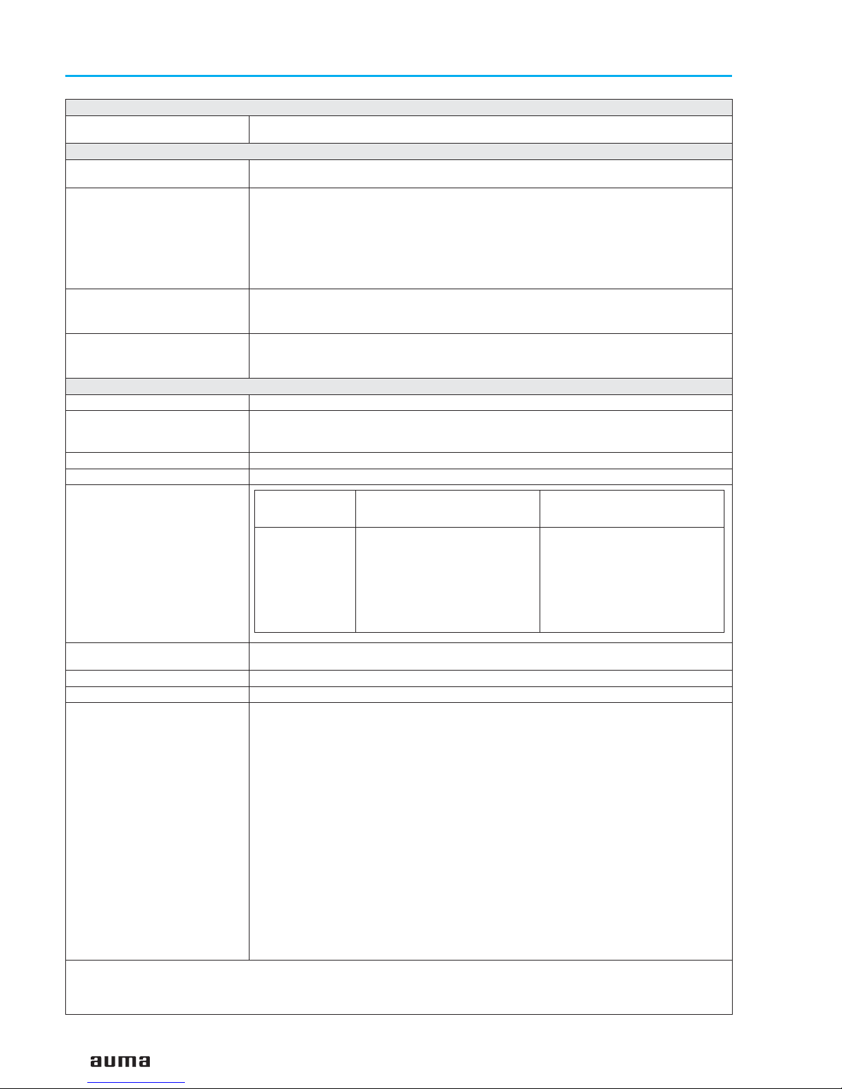
Settings/ programming of the Modbus interface
Setting of the Modbus interface The setting of baud rate, parity, and Modbus address is realised via the AUMA MATIC
Modbus assembly
Commands and signals of the Modbus interface
Oricess representation output
(command signals)
OPEN, STOP CLOSE, nominal position value
4)
Process representation input
(feedback signals)
End position OPEN, CLOSED
Actual position value
4)
Selector switch in position LOCAL/ REMOTE
Running indication
4)
(directional)
Torque switch OPEN, CLOSED
Limit switch OPEN, CLOSED
Manual operation by handwheel
4)
or local controls
Process representation input
(fault signals)
Motor protection tripped
Torque switch tripped in mid-travel
One phase missing
Behaviour on loss of
communication
The behaviour of the actuator is programmable:
- operation to end position OPEN or CLOSED
- operation to any intermediate position
4)
General Modbus data
Communication protocol Modbus RTU
Network topology Linear (BUS) structure. Active bus termination on both sides.
Coupling and uncoupling of devices during operation without affecting other devices is
possible.
Transmission medium Twisted, shielded copper cable according to EN 50 170
Modbus interface EIA-485 (RS485)
Transmission speed/
cable length
Device types Modbus slave, e.g. devices with digital and/ or analogue inputs and outputs, such as
actuators, sensors
Number of devices 32 devices within each segment without repeater, with repeater expandable up to 127
5)
Bus access Polling between master and slaves (query-response)
Supported Modbus functions
(services)
01 Read Coil Status
02 Read Input Status
03 Read Holding Registers
04 Read Input Registers
05 Force Single Coil
15 (0FHex) Force Multiple Coils
06 Preset Single Register
16 (10Hex) Preset Multiple Registers
07 Read Exception Status
17 (11Hex) Report Slave ID
08 Diagnostics:
00 00 Loopback
00 10 (0AHex) Clear Counters and Diagnostic Register
00 11 (0BHex) Return Bus Message Count
00 12 (0CHex) Return Bus Communication Error Count
00 13 (0DHex) Return Bus Exception Error Count
00 14 (0EHex) Return Slave Message Count
00 15 (0FHex) Return Slave No Response Count
4) Requires position transmitter (potentiometer or RWG) in actuator
5) The highest Modbus address which can be set at the AUMA MATIC is 127
Baud rate (kbit/s) Max. cable length (segment
length) without repeater
Possible cable length with
repeater (total network cable
length)
300
600
1,200
2,400
4,800
9,600
19,200
38,400
1,200 m
1,200 m
1,200 m
1,200 m
1,200 m
1,200 m
1,200 m
1,200 m
approx. 10 km
approx. 10 km
approx. 10 km
approx. 10 km
approx. 10 km
approx. 10 km
approx. 10 km
approx. 10 km
Page 9

9
Actuator controls AUMA MATIC AM/ AMExB/ AMExC
Operation instructions Modbus
Service conditions
Enclosure protection according
to EN 60 529
Standard: IP 67 (when mounted)
Options: IP 68
6)
DS3)Terminal compartment additionally sealed against interior (double
sealed)
Corrosion protection Standard: KN Suitable for installation in industrial units, in water or power plants
with a low pollutant concentration
Optionen: KS Suitable for installation in occasionally or permanently aggressive
atmosphere with a moderate pollutant concentration
(e.g. wastewater treatment plants, chemical industry)
KX Suitable for installation in extremely aggressive atmosphere with
high humidity and high pollutant concentration
KX-G Same as KX, however aluminium-free version (outer parts)
Finish coating Standard: Two-component iron-mica combination
Option: Special primer/special finish coat (customer’s choice)
Colour Standard: Silver-grey (DB 701, similar to RAL 9007)
Option: Other colours than standard colour are possible on request
Ambient temperature AM 01.1/ AM 02.1:
Standard: – 25 °C to + 70 °C
Options: – 40 °C to + 70 °C, low temperature version
– 50 °C to + 70 °C, extreme low temperature version, incl. heating system
– 60 °C to + 70 °C, extreme low temperature version, incl. heating system
AMExB
Standard: – 20 °C to + 40 °C
AMExC:
Standard: – 20 °C to + 40 °C
Options: – 40 °C to + 40 °C, low temperature version
– 50 °C to + 40 °C, extreme low temperature version, incl. heating system
Vibration resistance
7)
according to IEC 60 068-2-6
1 g, for 10 to 200 Hz
(only for actuator with controls. Not valid in combination with gearboxes)
Weight approx. 7 kg (with AUMA plug/ socket connector)
approx. 12 kg (with Ex-plug/ socket connector with terminal board)
Accessories
Wall bracket
8)
AUMA MATIC mounted separately from the actuator, including plug/ socket connector.
Connecting cables on request..
Recommended for high ambient temperatures, difficult access, or in case of heavy
vibrations during service.
Other information
EU Directives Electromagnetic Compatibility (EMC): (89/336/EEC)
Low Voltage Directive: (73/23/EEC)
Machinery Directive: (98/37/EC)
Reference documents Product description “Actuator controls AUMA MATIC”
Dimension sheets “Multi-turn actuators/ part-turn actuators with integral controls AUMA
MATIC”
3) Only in combination with AM 01.1 and AM 02.1
6) For version in enclosure protection IP 68, a higher corrosion protection KS or KX is strongly recommended
7) Resistant to vibrations during start-up or for failures of the plant. However, a fatigue strength may not be derived from this
8) Cable length between actuator and AUMA MATIC max. 100 m. Not suitable for version with potentiometer in the actuator. Instead of the potentiometer, an RWG
has to be used in the actuator.
Page 10
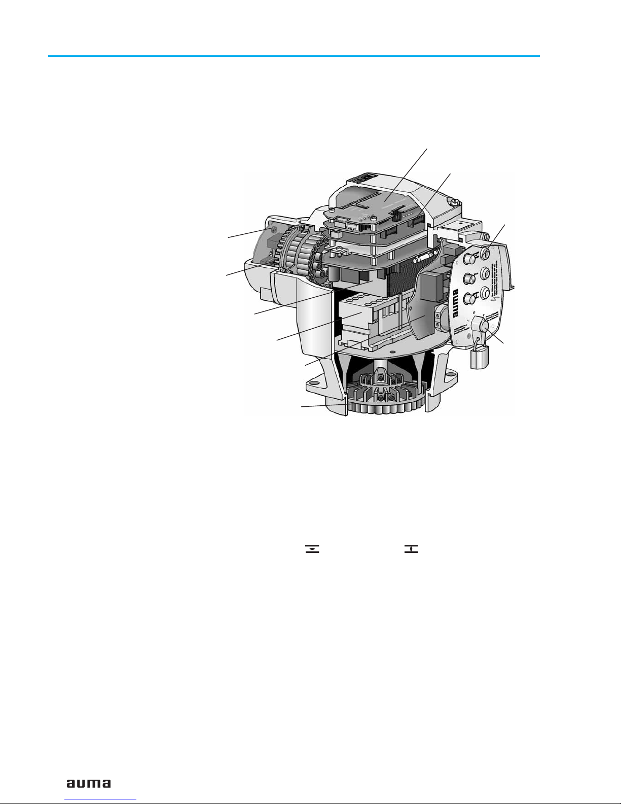
6. Design AUMA MATIC Modbus
The AUMA MATIC Modbus by AUMA represents the ideal controls for
connecting multi-turn actuators of the SA range and part-turn actuators of
the SG range to Modbus.
The integral controls AUMA MATIC Modbus consist of the following
modules:
.
Modbus interface. The interface links the Modbus data with the internal
electronics.
.
The logic board links the signals of the actuator with the local controls and the
Modbus interface and controls the reversing contactors or the thyristors.
.
Local controls with selector switch, push buttons, and indication lights.
The selector switch is used to select the control devices for the local
control LOCAL – 0 – REMOTE for remote control.
The push buttons (OPEN) – Stop – (CLOSE) are used for the
electric operation of the actuator on site.
.
Plug/ socket connectors for easy mounting of the AUMA MATIC Modbus
on the actuators.
.
Signal and control board with primary fuses, relays for conversion of the
local control commands into electrical signals, and indication lights as an
option.
.
Switchgear: Reversing contactors or thyristors for motor controls.
.
Modbus connection board with terminals for the Modbus cable and the
termination resistor for bus termination.
Actuators which have already been installed can be retrofitted for Modbus
by exchanging the controls AUMA MATIC for controls AUMA MATIC
Modbus.
10
Actuator controls AUMA MATIC AM/ AMExB/ AMExC
Modbus Operation instructions
Figure A: AUMA MATIC Modbus
Switchgear
Power supply unit
Logic board
Modbus interface
Plug/ socket connector
to actuator
Local controls
Selector switch
Signal and control board
Modbus
connection board
Electrical connection
with AUMA plug/ socket connector
Page 11
7. Electrical connection
.
Work on the electrical system or equipment must only be
carried out by a skilled electrician himself or by specially
instructed personnel under the control and supervision of
such an electrician and in accordance with the applicable
electrical engineering rules.
.
Installation regulations for Modbus must be observed for
the wiring.
(For literature references, please refer to appendix C)
Make sure to respect electromagnetic compatibility (EMC) when installing
cables:
Signal and bus cables are susceptible to interference.
Electric power cables are interference sources.
.
Lay cables being susceptible to inferference or sources of interference at
the highest possible distance from each other.
.
The interference immunity of signal and bus cables increases if the cables
are laid close to the ground potential.
.
Avoid long cables, if possible, or make sure that they are laid in locations
with low susceptibility to interference.
.
Avoid long parallel paths with cables being either interference sources or
susceptible to interference.
7.1 Power supply (standard) For explosion-proof version (type designation: AMExB/ AMExC), please
refer to page 15 or page 17.
.
Check whether type of current, supply voltage, and frequency comply with
motor data (refer to name plate at motor).
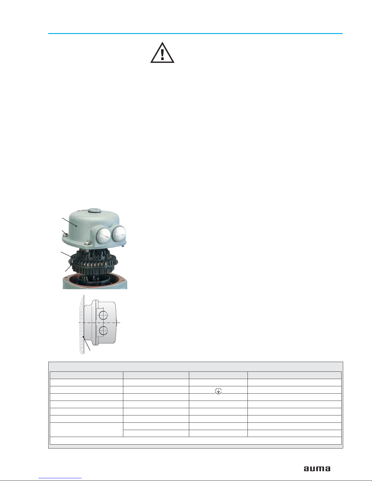
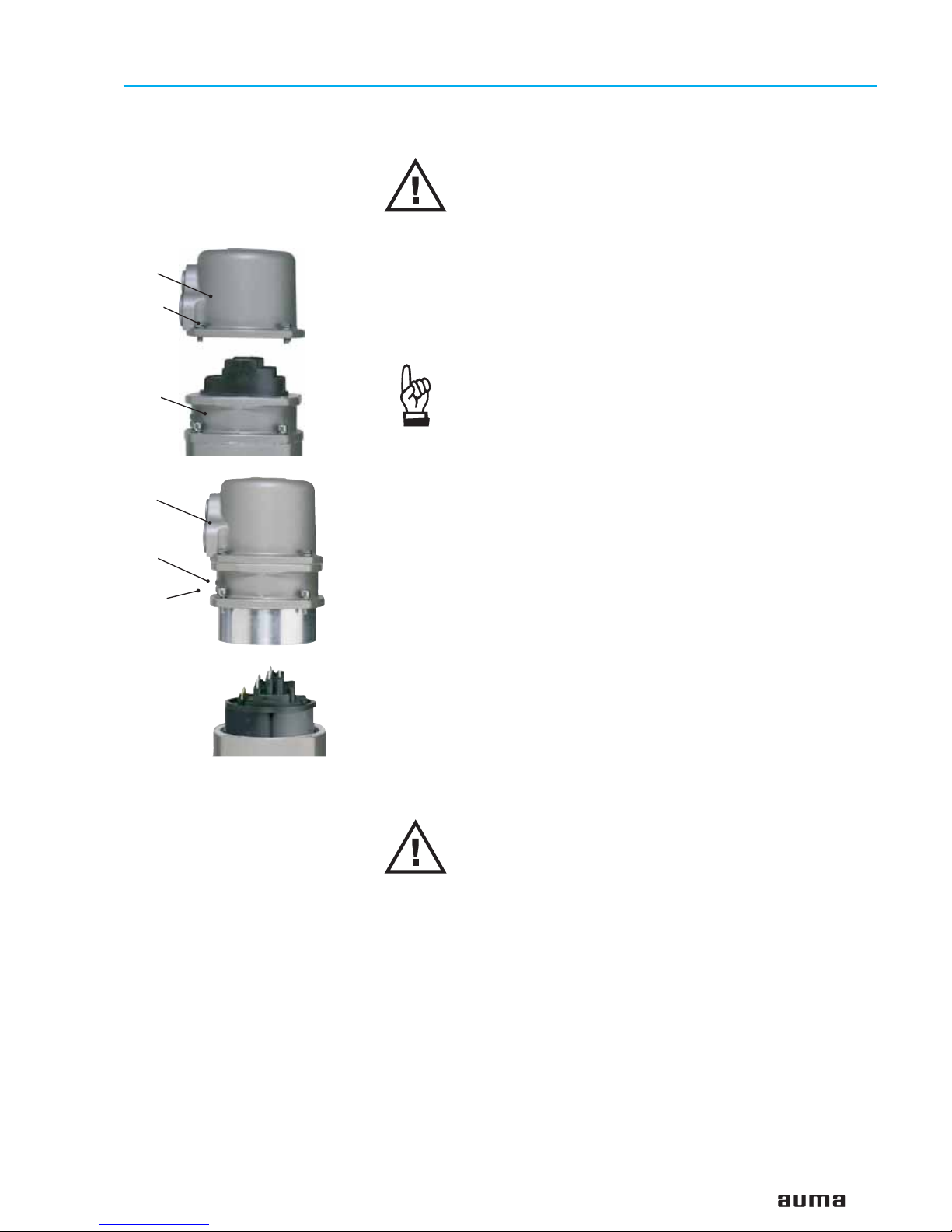
.
Loosen bolts (50.01) (figure B-1) and remove connection housing.
.
Loosen screws (51.01) and remove socket carrier (51.0) from plug cover
(50.0).
.
Insert cable glands suitable for connecting cables.
(The enclosure protection stated on the name plate is only ensured if suitable cable glands are used).
.
Seal cable entries which are not used with suitable plugs.
.
Connect cables according to order-related wiring diagram.
The wiring diagram applicable to the actuator is attached to the
handwheel in a weather-proof bag, together with the operation instructions. In case the wiring diagram is not available, it can be obtained from
AUMA (state commission no., refer to name plate) or downloaded directly
from the Internet (www.auma.com).
A special parking frame (figure B-2) for protection against touching the bare
contacts and against environmental influences, in case the electrical
connection has been removed, is available.
11
Actuator controls AUMA MATIC AM/ AMExB/ AMExC
Operation instructions Modbus
Figure B-1: Connection
50.0
50.01
51.0
51.01
Parking frame
Technical data Motor power connections1)Protective earth Control terminals
No. of contacts max. 6 (3 are used) 1 (leading contact) 50 pins / sockets
Marking U1, V1, W1, U2, V2, W2 1 to 50
Connecting voltage max. 750 V – 250 V
Nominal current max. 25 A –
16 A
Type of customer connection Screws Screw for ring lug Screws
Cross section max. 6 mm
2
6 mm
2
2.5 mm
2
Material: Pin/ socket carrier Polyamide
Polyamide Polyamide
Contacts Brass (Ms)
Brass (Ms)
Brass, tin plated or gold plated (option)
1)Suitable for copper wires. For aluminium wires, please contact AUMA
Table 2: Technical data AUMA plug/ socket connector for bus connection
Figure B-2: Parking frame (accessory)
Page 12
7.2 Bus connection (standard) For explosion-proof version (type designation: AMExB/ AMExC), please
refer to page 15 or page 17.
For version with FO (fibre optics), refer to separate operation instructions
“AUMA MATIC AM 01.1/ AM 02.1 FO connection”.
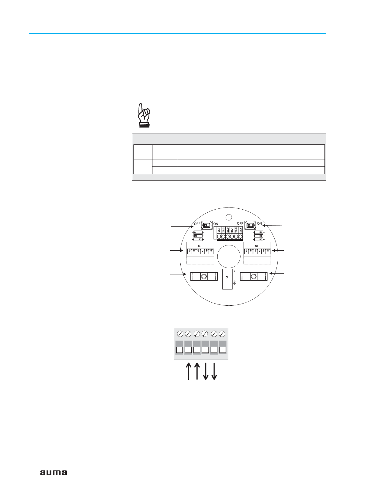
.
Connect bus cable. Refer to figures C-1 and C-4.
The termination resistors for channel 1 and channel 2 are switched in via
switches (S1) and (S2). Both switches are supplied in position ‘OFF’.
Only switch on the termination resistors (position ‘ON’) if the
actuator is the final device in the Modbus segment.
12
Actuator controls AUMA MATIC AM/ AMExB/ AMExC
Modbus Operation instructions
S1
ON Bus termination channel 1 ON
OFF Bus termination channel 1 OFF
S2
ON Bus termination channel 2 ON (option)
OFF Bus termination channel 2 OFF (option)
Table 3: Switch positions of S1 and S2
Figure C-1: Connection board (standard)
S1
Bus termination
channel 1
Connection
channel 1
Screening
S2
Bus termination
channel 2
(ption)
Connection
channel 2
(redundant)
Screening
X1
P/B
N/A
N/A
5V
P/B
GND
B
A
B
Figure C-2: Connection (standard)
from previous / to next
Modbus device
channel 1
Page 13
7.3 Fitting the cover After connection:
.
Insert the socket carrier (51.0) into the plug cover (50.0) and fasten it with
screws (51.01).
.
Clean sealing faces at the plug cover and the housing.
.
Check whether O-ring is in good condition.
.
Apply a thin film of non-acidic grease (e.g. Vaseline) to the sealing faces.
.
Replace plug cover (50.0) and fasten bolts (50.01) evenly crosswise.
.
Fasten cable glands with the specified torque to ensure the required
enclosure protection.
13
Actuator controls AUMA MATIC AM/ AMExB/ AMExC
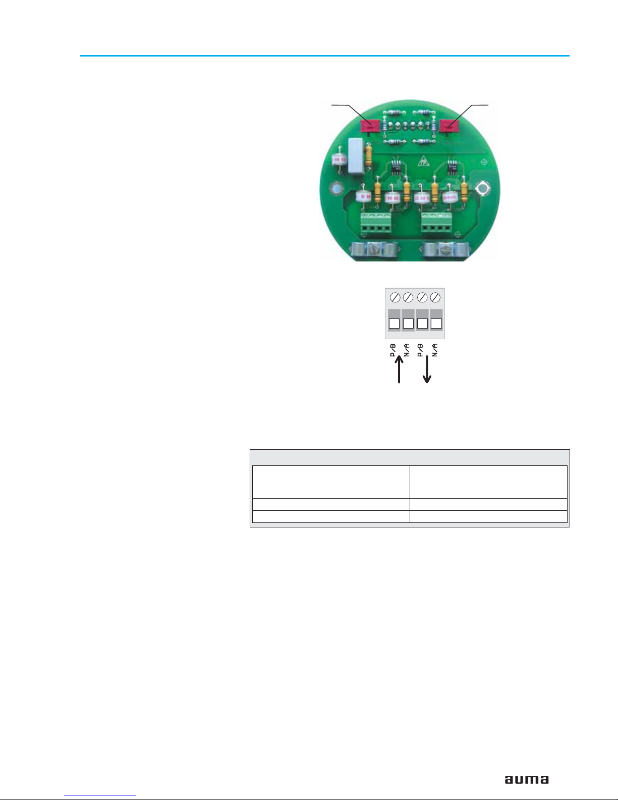
Operation instructions Modbus
Figure C-3: Connection board (for overvoltage protection)
S1
Bus termination
channel 1
S2
Bus termination
channel 2
X1
1234
Figure C-4: Connection for overvoltage protection
Modbus
cable
AUMA
labelling at the
connection
A N/A
B P/B
Table 4: Assignment of Modbus cable
from previous / to next
Modbus device
channel 1
Page 14

7.4 Remote position transmitter For the connection of remote position transmitters (potentiometer, RWG)
screened cables must be used.
7.5 AUMA MATIC on wall bracket The AUMA MATIC can also be mounted separately from the actuator on a
wall bracket.
.
For the connection of actuator and AUMA MATIC on wall bracket, use suitable flexible and screened connecting cables.
(Preconfectioned cables can be obtained from AUMA on request)
.
Permissible cable distance between actuator and AUMA MATIC amounts
to a max. of 100 m.
.
Versions with potentiometer in the actuator are not suitable. Instead of the
potentiometer, an RWG has to be used in the actuator.
.
Connect the wires in correct phase sequence.
Check direction of rotation before switching on.
The plug connection on the wall bracket is made as crimp version.
Use a suitable four indent crimp tool for crimping.
Cross sections for flexible wires:
Control cables: max. 0.75 to 1.5 mm²
Power supply: max. 2.5 to 4 mm²
The connector at the actuator is equipped with screw type connections.
Wire end sleeves have to be used.
7.6 Test run Perform test run. Please refer to the operation instructions pertaining to the
actuator (multi-turn actuator SA(R) ... / part-turn actuator SG ...).
Check limit and torque switching:
Check limit and torque switching, electronic position transmitter RWG or
potentiometer (option) and re-set where appropriate.
The settings are described in the operation instructions pertaining to the
actuator (multi-turn actuator SA(R) ... part-turn actuator SG ... ).
For actuators with feedback signal (RWG, potentiometer), a reference operation has to be performed after having changed the setting.
Perform reference operation:
.
Operate actuator electrically (via the push buttons OPEN and CLOSE of
the local controls) once to the end position OPEN and once to the end
position CLOSED.
.
If no reference operation is performed after changing the limit switching,
the feedback signal via the bus is not correct. The bus signals the missing
reference operation as warning (see page 28).
14
Actuator controls AUMA MATIC AM/ AMExB/ AMExC
Modbus Operation instructions
Figure C-5: AM on wall bracket
Connecting cable to actuator
Page 15
7.7 Mains and bus connection for Ex-version with plug/ socket connector / terminal board (KP)
When working in potentially explosive areas, observe the
European Standards EN 60079-14 “Electrical installations in
hazardous areas” and EN 60079-17 “Inspection and maintenance of electrical installations in hazardous areas”.
For the Ex-plug/ socket connector (figure D-1), the electrical mains connection is made after removing the plug cover (50.0) at the EEx e terminals of
the terminal board (51.0). The flameproof compartment (type of protection
EEx d) remains hereby closed.
.
Check whether type of current, supply voltage, and frequency correspond
to motor data (refer to name plate at motor).
.
Loosen bolts (50.01) (figure D-1) and remove plug cover.
.
Insert cable glands with “EEx e” approval and of size suitable for connecting cables. For the recommended cable
glands refer to appendix D, page 57.
(The enclosure protection stated on the name plate is only
ensured if suitable cable glands are used).
.
Seal cable entries which are not used with suitable plugs.
.
No more than max. 2 wires with the same cross section
may be connected to one terminal.
.
Remove cable sheathing in a length of 120 – 140 mm.
Strip wires: Controls max. 8 mm, motor max. 12 mm.
For stranded wires use end-sleeves according to DIN 46228.
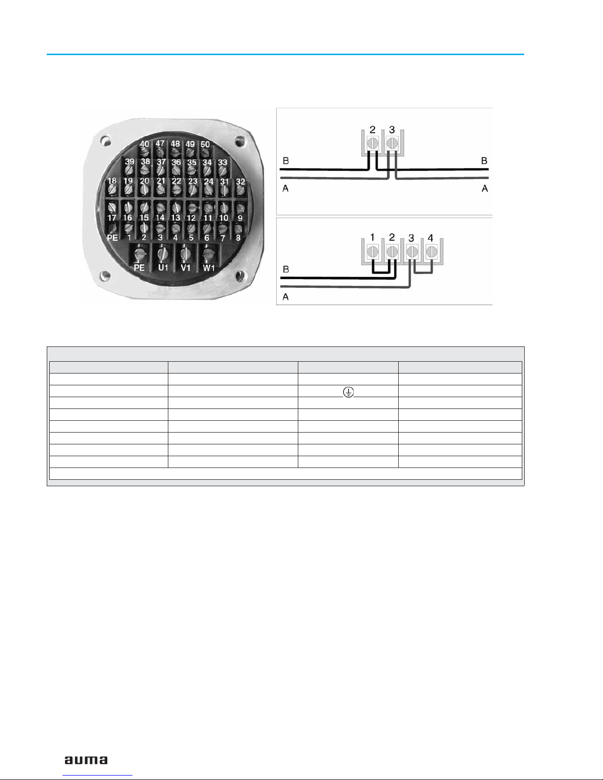
.
Connect bus cable. Refer to figure (D-3).
The termination resistor for channel 1 is connected through linking the
terminals 1 – 4 and 3 – 2 (standard).
.
Only connect the termination resistor if the actuator is the final device in
the Modbus segment.
.
Connect screen largely to the cable glands. For the recommended cable
glands refer to appendix D, page 57.
If the actuator must be taken from the valve, e.g. for service purposes, it can
be separated from the mains without having to remove the wiring
(figure D-2). For this purpose, the screws (51.02) are removed and the plug/
socket connector is pulled off. Plug cover (50.0) and terminal board (51.0)
remain together.
Flameproof enclosure! Before opening, ensure that no
explosive gas and no voltage is present.
A special parking frame (figure D-2) for protection against touching the bare
contacts and against environmental influences is available.
15
Actuator controls AUMA MATIC AM/ AMExB/ AMExC
Operation instructions Modbus
Figure D-1: Connection
50.0
50.01
51.0
Figure D-2: Disconnection from the mains
50.0
51.0
51.02
Page 16
16
Actuator controls AUMA MATIC AM/ AMExB/ AMExC
Modbus Operation instructions
Figure D-3: Bus connection for channel 1 (standard)
Another bus device follows the actuator
Actuator is final bus device
from previous
Modbus device
channel 1
to next
Modbus device
channel 1
Technical data Motor power connections
1)
Protective earth Control terminals
No. of contacts max. 3 1 (leading contact) 38 pins/ sockets
Marking U1, V1, W1 1 to 24, 31 to 50
Connecting voltage max. 550 V – 250 V
Nominal current max. 25 A – 10 A
Type of customer connection Screws Screws Screws
Cross section max. 6 mm
2
6 mm
2
1.5 mm
2
Material: Pin/ socket carrier Araldite/ Polyamide Araldite/ Polyamide Araldite/ Polyamide
Contacts Brass (Ms) Brass (Ms) Brass (Ms) tin-plated
1)Suitable for copper wires. For aluminium wires, please contact AUMA
Table 5: Technical data Ex plug/ socket connector with terminal board for explosion-proof actuators
Page 17

7.8 Mains and bus connection for Ex-version with plug-in terminal connection (KES)
When working in potentially explosive areas, observe the
European Standards EN 60079-14 “Electrical installations in
hazardous areas” and EN 60079-17 “Inspection and maintenance of electrical installations in hazardous areas”.
The bus connection is realised via terminals (figure E-1) The terminal
compartment is designed for explosion protection “EEx e” (increased
safety). The controls AUMA MATIC (type of protection EEx d) remain closed.
.
Loosen bolts (1) (figure E-1) and remove terminal cover.
.
Insert cable glands with “EEx e” approval and of size suitable for connecting cables. For the recommended cable
glands refer to appendix D, page 57.
(The enclosure protection stated on the name plate is only
ensured if suitable cable glands are used).
.
Seal cable entries which are not used with suitable plugs.
Cross sections for connection:
Control cables: max. 2.5 mm
2
Motor connection: max. 10 mm2,
Suitable bus cables, see page 19.
.
Connect bus cable to channel 1 according to configuration of the terminals (figure E-2).
The termination resistor for channel 1 is connected through linking the
terminals 1 – 2 and 3 – 4.
.
Only connect the termination resistors if the actuator is the final device in
the Modbus segment.
17
Actuator controls AUMA MATIC AM/ AMExB/ AMExC
Operation instructions Modbus
Figure E-1: Plug-in terminal
connection
Terminal
cover
Terminals
Terminal
board
Figure E-2: Terminal configuration for Ex connection (KES)
Another bus device
follows the actuator
Previous Next
Modbus device Modbus device
Actuator is last
bus device
Previous
Modbus device
Page 18

7.9 Redundant bus connection AUMA Modbus devices can be connected with a second (redundant)
Modbus cable. If the bus on channel 1 fails, e. g. through cable break, the
slave automatically switches to channel 2 after a waiting time.
Thus, the change-over is realised with a time delay (see parameter 5
“Time for channel changing in 0.1s”, page 35).
Additionally, the communication cannot be carried out on both channels
simultaneously.
If the redundancy is activated (see parameter 4 “Redundancy”, page 34),
the AUMA MATIC transmits its data using both channels but receives the
data only using the active channel.
This cable redundancy may only be applied after previous
integration test using the desired process control system!
.
For versions with AUMA plug/ socket connector (subclause 7.2):
Connect redundant bus cable to channel 2 in the same way as channel 1
(figure C-2).
.
For Ex-version with plug/ socket connector / terminal board (KP)
(subclause 7.7):
Connect cable B to terminal 6, cable A to terminal 7.
The termination resistor for channel 2 is connected through linking the
terminals 5 – 6 and 7 – 8.
.
For Ex-version with plug-in terminal connection (KES)
(subclause 7.8):
Connect cable B to terminal 6, cable A to terminal 7 (figure E-2).
The termination resistor for channel 2 is connected through linking the
terminals 5 – 6 and 7 – 8.
The setting of the redundant bus connection is realised via the parameters
4 and 5 (refert to pages 34, 35).
18
Actuator controls AUMA MATIC AM/ AMExB/ AMExC
Modbus Operation instructions
Page 19

7.10 Bus cables Only cables according to the recommendations of EIA 485 standard may be
used for Modbus wiring.
A maximum of up to 32 Modbus devices may be connected in one segment.
If more stations are to be connected to one Modbus network, several
segments must be connected with repeaters.
The bus cable must be laid at a distance of at least 20 cm from other cables.
It should be laid in a separate, conductive, and earthed cable trunking.
It must be ensured that there are no potential differences between the individual devices on the Modbus (perform a potential compensation).
The max. cable length without repeater amounts to 1,200 m (independent of
the baud rate).
Cable recommendation for Modbus
Characteristic impedance: 35 to 165 Ohm, at a measurement
frequency of 3 to 20 MHz.
Cable capacity: < 30 pF per metre
Core diameter > 0.64 mm
Core cross section: > 0.34 mm², corresponds to AWG 22
Loop resistance: < 110 Ohm per km
Screening: copper shielding braid or shielding braid and
shielding foil
19
Actuator controls AUMA MATIC AM/ AMExB/ AMExC
Operation instructions Modbus
Figure F: Example: Modbus with one secment
Bus termination
switched on
Bus termination
switched on
Modbus board
AUMA MATIC
Modbus
Connection
board
2-wire cable
Controls (master)
Page 20

7.11 Setting the Modbus interface
A correct communication is only possible if the settings of
the baud rate, the parity, and the stop bits agree with the
master settings.
The settings are realised on the Modbus interface board.
.
Loosen screws and remove cover (figure G-1)
20
Actuator controls AUMA MATIC AM/ AMExB/ AMExC
Modbus Operation instructions
Figure G-1
Screws
Modbus interface
board
Figure G-2: Modbus interface board
green LED illuminated
ADDRESS MODE ON
Push buttons:
T1 RESET
T2 MODIFY
T3 CHANGE MODE
LEDs: 7 6 5 4 3 2 1 0 L1 L2 L3 L4
Page 21

7.12 Setting the communication parameters
Push buttons:
T1 RESET
T2 MODIFY
T3 CHANGE MODE:
DEFAULT MODE: for status indication and basic programming,
ADDRESS MODE for address setting
BAUD RATE MODE for baud rate selection
Push button 3 (CHANGE MODE) is used to switch between the following
modes:
1) DEFAULT MODE is characterised by LED 7 (green) being switched off.
Display and modification of type of seating in end position CLOSED,
parity bits and stop bits as well as display of DataExchange, status,
BusActivity, and LocalError.
2) ADDRESS MODE is characterised by LED 7 (green) being illuminated.
The address is adjustable.
3) BAUD RATE MODE
is characterised by the blinking of LED 7 (green).The baud rate is adjustable.If no
push buttons are pressed for 30 seconds, the display will revert to DEFAULT MODE.
The push button MODIFY allows incrementation of the figure shown in the
LED row. The new value is immediately accepted in the DEFAULT MODE.
For ADDRESS MODE and BAUD RATE MODE, the value is only accepted
when leaving these modes.
7.13 Setting parameter seating mode in end position CLOSED, parity bits and number of stop bits
When not pressing push button CHANGE MODE, you are in the DEFAULT
MODE (LED 7 is not illuminated). LED 0, LED 1, and LED 2 show the value
of the three mentioned parameters:
Push button S3 “MODIFY” is used to set these parameters. If, for example,
type of seating in end position CLOSED = torque seating, parity setting =
even parity, and number of stop bits = 1 stop bit is to be selected, the combination 001 must be illuminated for the first 3 LEDs. The push button
“MODIFY” is operated until this combination appears. The parameter values
become immediately valid.
7.14 Setting the Modbus address The Modbus address is set using push buttons T2 and T3. This is done
according to the following sequence:
(a) Press push button T1 CHANGE MODE (hold down for 1 to 2 seconds):
The green LED 7 ADRESS MODE is illuminated (not blinking);
it indicates the programming mode for the Modbus address.
The actually set Modbus address is displayed as binary coding by LEDs
6 to 0 (1 to 127).
(b) Set desired bus address using push button T2 MODIFY:
(Factory setting: slave address 2)
(c) Each pressing of the push button increments the address value by one.
Address 1 will follow after address 127. If push button T2 MODIFY is
held down (approx. 1/3 s), the incrementation is done automatically.
21
Actuator controls AUMA MATIC AM/ AMExB/ AMExC
Operation instructions Modbus
LED Parameter LED on LED off
0 seating mode in end position CLOSED torque seating limit seating
1 Parity setting No Parity Even Parity
2 Number of stop bits 2 stop bits 1 stop bit
Page 22

(d) After setting the required Modbus address, quit the programming mode
by pressing key T3 CHANGE MODE. The newly set address now
becomes valid.
Pressing the key T3 results in changing to BAUD RATE MODE;
renewed pressing of key 3 results in reverting to DEFAULT MODE.
(e) Alternatively to clause d), pressing the push button T3 may be ommitted.
After 30 s the status address mode is automatically quit and the
DEFAULT MODE is indicated. The set address is thus accepted.
7.15 Setting the baud rate
The baud rate is selected with the push buttons T2 and T3. This is done
according to the following sequence:
(a) Press push button T3 CHANGE MODE (hold down for 1 to 2 seconds):
The green LED 7 is illuminated (not blinking): the ADDRESS MODE is
active.
(b) Press push button T3 CHANGE MODE again (hold down for 1 to 2
seconds): The green LED 7 is blinking: now, the BAUD RATE MODE is
active.
(c) Select the desired Modbus baud rate pressing push button T2 MODIFY.
(d) The baud rate setting changes each time, push button T2 is pressed.
After the setting 56,400 bit/s (1001), the setting 110 Bit/s (0000) follows
again. If push button T2 MODIFY is held down (approx. 1/3 s), the
incrementation is done automatically. Only the first 4 LEDs count as only
10 baud rate settings are possible.
(e) After setting the required Modbus baud rate, close the programming
mode by pressing push button T3. The newly set baud rate becomes
valid and the interface is in DEFAULT MODE.
(f) Alternatively to clause e), pressing the push button T3 CHANGE MODE
may be omitted. After 30 s, the BAUD RATE MODE status is
automatically quit and the DEFAULT MODE is indicated. The set baud
rate is thus accepted.
22
Actuator controls AUMA MATIC AM/ AMExB/ AMExC
Modbus Operation instructions
Setting
LED 3 LED 2 LED 1 LED 0
Baud rate
bit/s
Notes
0 0000
110
1 0001
300
2 0010
600
3 0011
1200
4 0100
2400
5 0101
4800
6 0110
9600 Default setting
7 0111
19200
8 1000
38400
Baud rate deviation
– 2.5 % !
9 1001
56400
Baud rate deviation – 5 %
(not recommended)
Page 23

8. Commissioning with controls
8.1 Introduction To commission a Modbus slave, a special configuration of the master using
a configuration file is usually not required.
The Modbus RTU transmission is based on a simple protocol containing the
slave address, a function code with offset address, the process data, and a
checksum.
8.2 Overview of the Modbus functions for data transmission
8.3 Modbus function and corresponding offset addresses of the AUMA MATIC
23
Actuator controls AUMA MATIC AM/ AMExB/ AMExC
Operation instructions Modbus
Function Function code
(decimal)
Description
Force Single Coil 05 Sets one single bit to ON or OFF within slave
Force Multiple Coils 15 Sets several subsequent bits to ON or OFF within slave
Read Coil Status 01 Reads the status of individual pieces of output bit information out of
the slave.
Read Input Status 02 Reads the status of individual pieces of input bit information out of the
slave
Preset Single Register 06 Writs data into one single holding register (16 bit) of slave
Preset Multiple Register 16 Writes data into subsequent holding registers
Read Input Register 04 Reads the content of input data register (16 bit) out of the slave
Read Holding Register 03 Reads the content of holding registers out of the slave
Action Permissible function func-
tion code (decimal)
Permissible offset
addresses (decimal)
Permissible offset addresses (hexadecimal)
Write or read process
representation output data
(master outputs)
Force Single Coil (05)
Force Multiple Coils (15)
Read Coil Status (01)
0 to 2 0x0000 to 0x0002
Preset Single Register (06)
Preset Multiple Register (16)
Read Holding Register (03)
4096 to 4098 0x1000 to 0x1002
Read process representation
input data (master inputs
Read Input Status (02) 8192 to 8239 0x2000 to 0x202F
Read Input Register (04) 12288 to 12296 0x3000 to 0x3008
Write or read parameters of
AUMA MATIC
Preset Single Register (06)
Preset Multiple Register (16)
Read Holding Register (03)
16384 to 16433 0x4000 to 0x4031
Page 24

9. Input data
9.1 Reading the actuator signals from the actuator using register functions
Functions to be used:
Read Input Register (04)
Grey bits are collective signals. They contain the results of a disjunction (OR
operation) of other information.
24
Actuator controls AUMA MATIC AM/ AMExB/ AMExC
Modbus Operation instructions
Offset
(hexadecimal)
Offset
(decimal)
Register contents
(For the description, refer to chapter 9.2)
0x3000 12288 Register 1: Locigal signalsMeldungen
0x3001 12289 Register 2: Actuator signals
0x3002 12290 Register 3: E2 Actual position
0x3003 12291 Register 4: Fault signals
0x3004 12292 Register 5: Warning signals
Bit15Bit14Bit13Bit12Bit11Bit10Bit9Bit
8
Bit7Bit6Bit5Bit4Bit3Bit2Bit1Bit
0
–
–
–
–
–
–
–
–
Fault ind.
Warning ind.
Running CLOSE
Running OPEN
–
Setpoint reached
CLOSED position
OPEN position
Bit15Bit14Bit13Bit12Bit11Bit10Bit9Bit
8
Bit7Bit6Bit5Bit4Bit3Bit2Bit1Bit
0
–
–
–
–
–
–
–
–
TSC (DSR)
TSO (DOEL)
LSC (WSR)
LSO (WOEL)
Local sw. position
Remote sw. position
Mains failure
Thermal fault
Bit15Bit14Bit13Bit12Bit11Bit10Bit9Bit
8
Bit7Bit6Bit5Bit4Bit3Bit2Bit1Bit
0
–
–
–
–
–
–
–
–
--
--
TSC (DSR) fault
TSO (DOEL) fault
Mains failure
Tthermal fault
Switch not REMOTE
Wrong command
Bit15Bit14Bit13Bit12Bit11Bit10Bit9Bit
8
Bit7Bit6Bit5Bit4Bit3Bit2Bit1Bit
0
–
–
–
–
–
–
–
–
–
–
No reference operation
Hardware fault
Potentiometer fault
Loss of transm. signal
Channel 2 active
24 V power failure
Page 25

To ensure that the actuator gives a correct end position
signal after power failure in end position CLOSED/ OPEN, we
recommend to evaluate the information LSC (WSR)/
LSO (WOEL) (bit 5/4 in register 2) for the end position signal
CLOSED/ OPEN.
25
Actuator controls AUMA MATIC AM/ AMExB/ AMExC
Operation instructions Modbus
Offset
(hexadecimal)
Offset
(decimal)
Register contents
(For the description, refer to chapter 9.2)
0x3005 12293 Register 6: Physical operation
0x3006 12294 Register 7: Options
0x3007 12295 Register 8: First analogue input (wiring diagram designation: analogue 2)
0x3008 12296 Register 9: Second analogue input (wiring diagram designation: analogue 3/4)
Bit15Bit14Bit13Bit12Bit11Bit10Bit9Bit
8
Bit7Bit6Bit5Bit4Bit3Bit2Bit1Bit
0
–
–
–
–
–
–
–
–
–
Analogue 3/4 loss
Analogue 2 loss
–
Dig. input 4
Dig. input 3
Dig. input 2
Dig. input 1
Bit15Bit14Bit13Bit12Bit11Bit10Bit9Bit
8
Bit7Bit6Bit5Bit4Bit3Bit2Bit1Bit
0
–
–
–
–
–
–
–
–
Local CLOSE
Local OPEN
Remote CLOSE
Remote openF
Start stepping mode
Operation pause
–
Rev.prev. /dead time
Page 26

9.2 Description of the input data
Register 1: Logical signals
Important signals from the
actuator concerning errors,
warnings, operations:
26
Actuator controls AUMA MATIC AM/ AMExB/ AMExC
Modbus Operation instructions
Bit Designation Value Description
0
OPEN
position
Limit seating
in end position OPEN
1 Limit switch in direction OPEN operated.
0 other
1
CLOSED
position
Limit seating
in end position CLOSED
1 Limit switch in direction CLOSE operated.
0 other
CLOSED
position
Torque seating in end position
CLOSED
1
Torque switch and limit switch in direction CLOSE operated.
0 other
2
Setpoint
reached
1
The setpoint is within max. error variable (outer dead
band). Signal occurs only if Modbus master has set
the Setpoint reached bit.
0 other
3
—
1
(reserved for extensions)
0
4
Running
OPEN
1
Operation command (OPEN or SETPOINT) from
Modbus in direction OPEN is executed. For operation
in stepping mode, this signal is also active during an
off-time, the dead time, and the reversing prevention.
0 No operation is carried out via Modbus.
5
Running
CLOSED
1
Operation command (CLOSE or SETPOINT) from
Modbus in direction CLOSE is executed. For operation in stepping mode, this signal is also active during
an off-time, the dead time, and the reversing prevention.
0 No operation is carried out via Modbus.
6
Warning ind.
1
One or several warnings have occurred.
Collective signal: Contains the result of a disjunction
(OR operation) of all bits of the register “Warning signals (page 28)
0
No warnings are active (all bits of the warnings cancelled).
7
Fault ind.
1
One or several faults have occurred so that the actuator can no longer be controlled via Modbus (at least
one bit set in fault byte).
Collective signal: Contains the result of a disjunction
(OR operation) of all bits of the register “Fault signals”
(page 27).
0
No faults are active (all bits are cancelled in fault register).
Page 27

Register 2: Actuator signals
Basic signals originating from
the logic
Register 3: E2 Actual position
Actual actuator position,
complete value,
or low register
Register 4: Fault signals
The actuator is not ready for
remote operation. As soon as
one of these signals is set, bit
7 of register1 will also beset.
27
Actuator controls AUMA MATIC AM/ AMExB/ AMExC
Operation instructions Modbus
Bit Designation Value Description
0
Thermal fault
1 A thermal fault (motor protection) has occurred.
0 No thermal fault has occurred.
1
Mains fault
1 A mains failure has occurred, e.g. phase error.
0 No mains failure has occurred.
2
Remote sw.
position
1 Selector switch in position REMOTE.
0 Selector switch not in position REMOTE.
3
Local sw.
position
1 Selector switch in position LOCAL.
0 Selector switch not in position LOCAL.
4
LSO (WOEL)
1 Limit switch OPEN left operated.
0 Limit switch OPEN left not operated.
5
LSC (WSR)
1 Limit switch CLOSE right operated.
0 Limit switch CLOSE right not operated.
6
TSO (DOEL)
1 Torque switch OPEN left operated (storing).
0 Torque switch OPEN left not operated.
7
TSC (DSR)
1 Torque switch CLOSE right operated (storing).
0 Torque switch CLOSE right not operated.
Condition Value
Parameter 2 (measured data coding position transmitter) = 0
Value range 0..100 %
Parameter 2 (measured data coding position transmitter) = 1
Value range 0..1000 %
Bit Designation Value Description
0
Wrong
command
1
Indicates the fact that several operation commands
were received simultaneously via Modbus (e.g. Remote
OPEN and Remote CLOSE simultaneously or Remote
CLOSE/ Remote OPEN and Remote SETPOINT (nominal) simultaneously) or that the max. value for a nominal
position has been exceeded (setpoint > 1000 or > 100).
0 Operation commands correct
1
Selector not
remote
1 Selector switch: position LOCAL or OFF
0 Selector switch: position REMOTE
2
Thermal fault
1
Motor protection has tripped; remedy: resetting local
controls via selector switch position RESET after the
motor has cooled off.
0 other
3
Mains failure
1 Loss of one phase or incorrect phase sequence.
0 other
4
TSO (DOEL)
fault
1
Torque fault OPEN occurred (only torque or torque before limit, according to type of seating); remedy: resetting using counter command.
0 other
5
TSC (DSR)
fault
1
Torque fault CLOSED occurred (only torque or torque
before limit, according to type of seating); remedy: re
-
setting using counter command.
0 other
Page 28

Register 5: Warning signals
The warning signals serve
only information purposes
and do not interrupt or cancel
an operation (as opposed to
faults). As soon as one of
these signals is set, bit 6 of
register 1 will be set simultaneously.
Register 6: Physical operation
28
Actuator controls AUMA MATIC AM/ AMExB/ AMExC
Modbus Operation instructions
Bit Designation Value Description
6
—
1
not assigned (reserved for extensions)
0
7
—
1
not assigned (reserved for extensions)
0
Bit Designation Value Description
0
Failure 24 V
supply
1
Failure 24 V supply voltage (internal 24 V DC supply
outside the permissible range).
0 other
1
Channel 2
active
1 Actuator uses channel 2 for communication.
0 other
2
Loss of
transm. sig-
nal
1
Signal interrupted at position transmitter RWG: For
recognition purposes, parameter 1 must be set to
value 3 (RWG 4 – 20 mA).
0 other
3
Potentio-
meter fault
1
Potentiometer fault: in end position CLOSED a value
is measured being higher than the one in end position
OPEN.
0 other
4
Hardware-
fault
1
Hardware fault: If this bit is set, the Modbus board
must be checked/ replaced.
0 other
5
No reference
operation
1
No reference operation: The values of the position transmitter cannot be used as long as the reference operation
(end position OPEN, en position CLOSED) has not been
performed. A nominal operation is not possible.
0 other
6
—
1
not assigned (reserved for extensions)
0
7
—
1
not assigned (reserved for extensions)
0
Bit Designation Value Description
0
Rev.prev./
dead time
1
Reversing prevention/ dead time warning: The actuator does not start as long as reversing prevention or
dead time is still active. The bit is set if a operation
command is available which cannot be executed immediately. The bit is cancelled as soon as the actuator
starts
0 other
1
—
1
not assigned (reserved for extensions)
0
2
Operation
pause
1 Operation pause
0 other
3
Start step-
ping mode
1
Indicates that the actuator is within the stepping range
during active stepping mode. Conditions: position
transmitter is provided, stepping mode is active, remote operation is being performed.
0 other
Page 29

Register 7: Options
Digital inputs and signal loss
at analogue inputs
Register 8: First analogue input (wiring diagram designation analogue 2)
The data content depends on parameter 22 (coding analogue 2), holding
register offset: 0x4015 (hexadezimal), 16405 (dezimal)
Settings:
0: 0 to 100 percent (default value)
1: 0 to 1000 per mil
2: 0 to 1023 (raw value of analogue-digital converter, not standardised)
29
Actuator controls AUMA MATIC AM/ AMExB/ AMExC
Operation instructions Modbus
4
Remote
OPEN
1
Remote operation via Modbus in direction OPEN (re
mote operation bit for logic board set and movement of
potentiometer detected). Signalling of this bit requires
a position transmitter.
0 other
5
Remote
CLOSE
1
Remote operation via Modbus in direction CLOSE (remote operation bit for logic board set and movement of
potentiometer detected). Signalling of this bit requires
a position transmitter.
0 other
6
Local OPEN
1
Actuator runs locally in direction OPEN (local controls
or handwheel).
Signalling of this bit requires a position transmitter.
0 other
7
Local
CLOSE
1
Actuator runs locally in direction CLOSE (local controls
or handwheel). Signalling of this bit requires a position
transmitter.
0 other
Bit Designation Value Description
0
Dig.
input 1
1 Digital input Nr. 1 = 1 (switch closed)
0 Digital input Nr. 1 = 0 (switch open)
1
Dig.
input 2
1 Digital input Nr. 2 = 1 (switch closed)
0 Digital input Nr. 2 = 0 (switch open)
2
Dig.
input 3
1 Digital input Nr. 3 = 1 (switch closed)
0 Digital input Nr. 3 = 0 (switch open)
3
Dig.
input 4
1 Digital input Nr. 4 = 1 (switch closed)
0 Digital input Nr. 4 = 0 (switch open)
4
—
1
Not assigned (reserved for extensions)
0
5
Analogue 2
loss
1
Signal interrupted at analogue input 2 (first free analogue input) i.e. the measured value is more than 0.2
mA lower than the set minimum value.
0 no signal interruption analogue input 2 detected
6
Analogue 3/4
loss
1
Signal interrupted at analogue input 3/4 (second free
analogue input) i.e. the measured value is more than
0.2 mA lower than the set minimum value.
0 no signal interruption analogue input 3/4 detected
7
—
1
not assigned (reserved for extensions)
0
Page 30

Register 9: Second analogue input (wiring diagram designation analogue 3/4)
The data content depends on parameter 25 (coding analogue 3/4), holding
register offset: 0x4018 (hexadecimal), 16408 (decimal)
Settings:
0: 0 to 100 percent (default value)
1: 1 to 1000 per mil
2: 0 to 1023 (raw value of analogue-digital converter, not standardised)
9.3 Reading the feedback signals from the actuator using status functions
Functions to be used:
Read Input Status (02)
Grey bits are collective signals. They contain the results of a disjunction (OR
operation) of other information.
30
Actuator controls AUMA MATIC AM/ AMExB/ AMExC
Modbus Operation instructions
Offset
(hexadecimal)
Offset
(decimal)
Content
(Description in subclause 9.2)
0x2000 8192 OPEN position
0x2001 8193 CLOSED position
0x2002 8194 Setpoint reached
0x2003 8195 - -
0x2004 8196 Running OPEN
0x2005 8197 Running CLOSE
0x2006 8198
Warning signals
(refer to page 28, register 5)
0x2007 8199 Error signals (refer to page 27, register 4)
0x2008 8200 Thermal fault
0x2009 8201 Mains failure (phase loss)
0x200A 8202 Selector switch REMOTE
0x200B 8203 Selector switch LOCAL
0x200C 8204 LSO (WOEL)
0x200D 8205 LSC (WSR)
0x200E 8206 TSO (DOEL)
0x200F 8207 TSC (DSR)
0x2010 8208 Wrong command
0x2011 8209 Selector switch not remote
0x2012 8210 Thermal fault
0x2013 8211 Mains failure (phase loss)
0x2014 8212 TSO (DOEL) fault
0x2015 8213 TSC (DSR) fault
0x2016 8214 - -
0x2017 8215 - -
0x2018 8216 24 V power supply failure
0x2019 8217 Channel 2 active
Page 31

31
Actuator controls AUMA MATIC AM/ AMExB/ AMExC
Operation instructions Modbus
Offset
(hexadecimal)
Offset
(decimal)
Content
(Description in subclause 9.2)
0x201A 8218 Signal loss position transmitter
0x201B 8219 Potentiometer fault (wrong polarity)
0x201C 8220 Hardware fault
0x201D 8221 No reference operation
0x201E 8222 - -
0x201F 8223 - -
0x2020 8224 Rev.prev./ dead time
0x2021 8225 - -
0x2022 8226 Operation pause
0x2023 8227 Start stepping mode
0x2024 8228 Remote OPEN
0x2025 8229 Remote CLOSE
0x2026 8230 Local OPEN
0x2027 8231 Local CLOSE
0x2028 8232 Digital input 0
0x2029 8233 Digital input 1
0x202A 8234 Digital input 2
0x202B 8235 Digital input 3
0x202C 8236 - -
0x202D 8237 Singal loss customer analogue input 1
0x202E 8238 Signal loss customer analogue input 2
0x202F 8239 - -
Page 32

10. Process representation output
Via the process representation output, the master (controls) can control the
slave (actuator).
10.1 Transmitting operation commands to or reading out from the actuator using register functions
Functions to be used:
Preset Single Register (06); Preset Multiple Register (16);
Read Holding Register (03)
10.2 Description of the output data
Register 1: Commands (high byte)
With the bits 0 – 2, the operation commands are transmitted to the actuator.Only one of
these bits may be set at any
given time. If remote
SETPOINT is set, the value of
the nominal position
(register 2) is used.
Bits3–15arereserved for future extensions and must remain set to 0.
As soon as these bits are written to via coil functions, the
contents of the respective
Holding Registers for the operation commands will also
change.
If the Coil Remote SETPOINT
is used, the respective
setpoint has to be entered on
the setpoint register.
32
Actuator controls AUMA MATIC AM/ AMExB/ AMExC
Modbus Operation instructions
Offset
(hexadecimal)
Offset
(decimal)
Register contents
0x1000 4096
Register 1: Commands
0x1002 4098
Register 2: E1 Setpoint
Holding register operation commands also change the corresponding coils for operation commands.
Operation commands which cannot be executed are rejected with ILLEGAL DATA VALUE (code 03). Operation commands
cannot be executed if a thermal fault or mains failure have occurred, or if the local controls are not set to remote, or if
commands are contradictory.
If a thermal fault or a mains failure occurs during remote operation, or if the remote operation is switched off via the selector
switch, the actuator will cancel all pending operation commands
Bit Designation Value Description
0
Remote
OPEN
1 Running OPEN
0 Not running OPEN
1
Remote
CLOSED
1 Running CLOSE
0 Not running CLOSE
2
Remote
SETPOINT
1
Running to setpoint
Can only be set if a position transmitter e.g. potentiom-
eter/ RWG (options) is available.
0 Not running to setpoint.
3
- -
1
Not assigned (reserved for extensions)
0
4
- -
1
Not assigned (reserved for extensions)
0
5
- -
1
Not assigned (reserved for extensions)
0
6
- -
1
Not assigned (reserved for extensions)
0
7
- -
1
Not assigned (reserved for extensions)
0
Bit15Bit14Bit13Bit12Bit11Bit10Bit9Bit
8
Bit7Bit6Bit5Bit4Bit3Bit2Bit1Bit
0
0
0
0
0
0
0
0
0
0
0
0
0
0
Remote SETPOINT
Remote CLOSED
Remote OPEN
Page 33

Register 2: E1 Setpoint
The setpoint can be transmit
ted either as a value between
0 – 100 (percent) or 0 – 1000
(per mil). The cange-over between 0 – 100 and 0 – 1000is
realised via parameter 2
“Measured data coding position transmitter”. According to
this programming, different
maximum values apply. When
these limits are exceeded, the
actuator stops and signals a
fault.
10.3 Transmission of operation commands to the actuator using coil functions
Functions to be used:
Force Single Coil (05)
Force Multiple Coils (15)
Read Coil Status (01)
If a Force Coil is set, the other two coils will be deleted by the actuator
(the actuator executes the last command issued).
Coil operation commands also change the corresponding holding register
for the operation commands.
Operation commands which cannot be executed are rejected with ILLEGAL
DATA VALUE (code 03). Operation commands cannot be executed if:
.
a thermal fault or a power failure have occurred.
.
the remote controls is not set to REMOTE.
.
an impermissible nominal value has been set (>100 or >1000).
.
commands are contradictory (coil contents at Force Multiple Coils or
holding registers contradictory).
If a thermal fault or a power failure occurs during remote operation or if the
remote operation is switched off, the actuator will cancel the pending operation commands.
33
Actuator controls AUMA MATIC AM/ AMExB/ AMExC
Operation instructions Modbus
Condition Value
Parameter 2 (measured data coding position transmitter) = 0
Setpoint 0...100 %
Parameter 2 (measured data coding position transmitter) = 1
Setpoint 0...1000 %
Byte 2: Setpoint 0...100 or setpoint 0...1000
Offset
(hexadecimal)
Offset
(decimal)
Contents
(Description in page 41)
0x0000 0 REMOTE OPEN
0x0001 1 REMOTE CLOSED
0x0002 2 REMOTE SETPOINT
Page 34

11. Operation parameters of the actuator
Functions to be used:
The parameters of the AUMA MATIC can be written or read using the
following functions:
Preset Single Register (06),
Preset Multiple Register (16), or
Read Holding Register (03)
Parameters should only be changed as a whole parameter record in order to
avoid inconsistent parameter records. The Modbus software checks the
consistency of parameters and refuses inconsistent parameter records
(ILLEGAL DATA VALUE, code 03).
Parameter 1 “Position transmitter”
Holding Register Offset: 0x4000 (hex.), 16384 (decimal)
Default value (standard setting): 1
0: The actuator is not equipped with a position transmitter.
1: The actuator is equipped with a potentiometer without RWG.
Switch S1.2 on Modbus board must be switched off!
2: Actuator is equipped with an RWG 0 – 20 mA.
For this position transmitter, the signal interruption noitoring is not active.
Switch S1.2 must be switched on!
3: Actuator is equipped with an RWG 4 – 20 mA.
For this position transmitter, the signal interruption monitoring is active.
Switch S1.2 on Modbus board must be switched on!
Parameter 2 “Measured data coding position transmitter”
Holding Register Offset: 0x4001 (hexadecimal), 16385 (decimal)
Default value: 0
0: Feedback signal (register 3, E2 actual position) 0 to 100 percent,
resolution is 1 %,
setpoint (register 2, E1 actual position) 0 to 100 percent.
1: Feedback signal (register 3, E2 actual position) 0 to 1000 per mil,
resolution is 0.1 %,
setpoint (register 2, E1 actual position) 0 to 1000 per mil.
Parameter 3 “Reversing prevention in ms”
Parameter for setting the waiting time in between a change of direction.
If necessary, adjust the value to the mechanics to prevent destruction
caused by excessively fast changes of direction.
Holding Register Offset: 0x4002 (hexadecimal), 16386 (decimal)
Default value: 200
lowest value: 100 (0.1s)
maximum value: 1000 (1 s)
Parameter 4 “Redundancy”
Holding Register Offset: 0x4003 (hexadecimal), 16387 (decimal)
Default value 0
0: no cable redundancy (only the first channel is used for communication).
1: Cable redundancy is switched on (first and second communication
channel connected).
34
Actuator controls AUMA MATIC AM/ AMExB/ AMExC
Modbus Operation instructions
Page 35

Parameter 5 “Time for channel changing in 0.1 s”
Indicates the time after which the channel is changed if no process data, i.e.
expiry of connection control time of 0.1 s, is received. This parameter is only
effective if the cable redundancy (parameter 4) is switched on.
Holding Register Offset: 0x4004 (hexadecimal), 16388 (decimal)
Default value: 50
lowest value: 50 (5 s)
maximum value: 6000 (10 min)
Parameter 6 “Failure behaviour”
Failure operation on failure of connection.
The parameters set in the most recent connection also apply to the failure
behaviour after interruption and restoring of the voltage supply.
Holding Register Offset: 0x4005 (hexadecimal), 16389 (decimal)
Default value: 0
0: Failure behaviour switched off (parameters 7, 8, 9 insignificant)
1: Simple failure behaviour switched on.
A failure operation will only be started if a connection to the master
(process data exchange) was already available.
2: Extended failure behaviour switched on.
If extended failure behaviour is switched on, a failure operation can be initiated immediately after the actuator has been
switched on.
Parameter 7 “Delay time for failure operation 0.1 s”
Delay time for failure operation in 0.1 s.
Indicates the down time of process data exchange after which a failure operation will be started. If the exchange is restored during this time, no failure
operation will be performed.
Holding Register Offset: 0x4006 (hexadecimal), 16390 (decimal)
Default value: 30
lowest value: 0 (actuator reacts immediately)
maximum value: 12,000 (actuator reacts after 20 minutes)
Parameter 8 “Failure operation”
Holding Register Offset: 0x4007 (hexadecimal), 16391 (decimal)
Default value 0
0: The actuator stops (STOP).
1: Actuator runs CLOSE
2: Actuator runs OPEN
3: Actuator runs to failure position.
If no position transmitter is installed (parameter 1 = 0), value 3 is not
permitted. In this case, the parameter record is rejected.
Parameter 9 “Failure position in per mil”
Actuator runs to the pre-set failure position.
This parameter is only effective if parameter 8 (failure operation) is set to
value 3, and if parameter 6 (failure behaviour) is not 0.
Holding Register Offset: 0x4008 (hexadecimal), 16392 (decimal)
Default value: 0
lowest value: 0 (end position CLOSED)
maximum value: 1,000 (end position OPEN)
35
Actuator controls AUMA MATIC AM/ AMExB/ AMExC
Operation instructions Modbus
Page 36

Parameter 10: not used
For detailed descriptions of parameters 11 to 14, please refer to
subclause 12.2
Parameter 11 “Dead time positioner in 0.1 s”
Indicates the dead time which has to be maintained between two motor
starts. In case the Modbus master issues a command before that time, the
AUMA MATIC delays the actuator reaction until dead time has expired.
Holding Register Offset: 0x400A (hexadecimal), 16394 (decimal)
The Modbus master of the controls must ensure that the
maximum number of motor starts of the actuator is not
exceeded.
Default value: 0
minimum value: 0 (actuator reacts immediately)
maximum value: 600 (actuator delays reaction by 1 minute max.)
Parameter 12 “Overrun direction OPEN in per mil”
The motor is switched off as soon as the distance between the actuator
position and the nominal position reaches this value. This is only valid for
operations in direction OPEN.
This parameter must be lower than the value in parameter 14 (max. error in
per mil).
Holding Register Offset: 0x400B (hexadecimal), 16395 (decimal)
Default value: 5
minimum value: 0 (no overrun in direction OPEN)
maximum value: 100 (10 % overrun in direction OPEN)
Parameter 13 “Overrun direction CLOSE in per mil”
The motor is switched off as soon as the distance between the actuator
position and the nominal position reaches this value. This is only valid for
operations in direction CLOSE.
This parameter must be smaller than the value in parameter 14 (max. error
in per mil).
Holding Register Offset: 0x400C (hexadecimal), 16396 (decimal)
Default value: 5
minimum value: 0 (no overrun in direction CLOSE)
maximum value: 100 (10 % overrun in direction CLOSE)
Parameter 14 “Max. error in per mil”
The actuator will only be restarted if the distance between the nominal position and the actual position is higher than this value.
Corresponds to the outer dead band.
This parameter must be higher than the value in parameter 12 (overrun in
direction OPEN) and parameter 13 (overrun in direction CLOSE).
The parameter must be set sufficiently high to ensure a
stable function of the positioner. If the value is set too low,
the actuator moves continuously within nominal value range
which will result in reducing the life time of the actuator.
Holding Register Offset: 0x400D (hexadecimal), 16397 (decimal)
Default value: 10
minimum value: 1 (0,1 % error).
maximum value: 100 (10 % error).
36
Actuator controls AUMA MATIC AM/ AMExB/ AMExC
Modbus Operation instructions
Page 37

Parameters 15 to 19 are not used
Parameter 20 “Start analogue 2 in 0.1 mA”
Current value at which the measuring range of analogue 2 input (option)
begins. This value must be smaller than the value in parameter 21 (end
analogue 2 in 0.1 mA). If a sensor with 4 – 20 mA signal is connected to the
analogue 2 input, the value must be set to 40.
Holding Register Offset: 0x4013 (hexadecimal), 16403 (decimal)
Default value: 0
minimum value: 0 (value for sensor with 0 – 20 mA signal)
maximum value: 150
important value: 40 (this corresponds to the correct value for a sensor with a
4 - 20 mA signal)
Parameter 21 “End analogue 2 in 0.1 mA”
Current value at which the measuring range of analogue 2 input (option)
ends. This value must be higher than the value in parameter 20 (start
analogue 2 in 0.1 mA).
Holding Register Offset: 0x4014 (hexadecimal), 16404 (decimal)
Default value: 200
minimum value: 50
maximum value: 200 (value for sensor with 0 – 20 or 4 – 20 mA signal)
Parameter 22 "Coding analogue 2"
Holding Register Offset: 0x4015 (hexadecimal), 16405 (decimal)
Default value: 0
0: 0 to 100 percent
1: 0 to 1000 per mil
2: 0 to 1023 (raw value of analogue-digital converter, not standardised)
Parameter 23 “Start analogue 3/4 in 0.1 mA”
Current value at which the measuring range of analogue 3/4 input begins.
This value must be smaller than the value in parameter 24 (end
analogue 3/4).
If a sensor with a 4 – 20 mA signal is connected to analogue 3/4, the value
must be set to 40.
Holding Register Offset: 0x4016 (hexadecimal), 16406 (decimal)
Default value 0
minimum value: 0 (value for sensor with 0 – 20 mA output)
maximum value: 150
important value: 40 (this corresponds to the correct value for a sensor with a
4 – 20 mA signal)
Parameter 24 “End analogue 3/4 in 0.1 mA”
Current value at which the measuring range of analogue 3/4 input ends.
This value must be higher than the value in parameter 23 (start
analogue 3/4).
Holding Register Offset: 0x4017 (hexadecimal), 16407 (decimal)
Default value: 200
minimum value: 50
maximum value: 200 (value for sensor with 0 – 20 mA or 4 – 20 mA output)
37
Actuator controls AUMA MATIC AM/ AMExB/ AMExC
Operation instructions Modbus
Page 38

Parameter 25 “Coding analogue 3/4”
Holding Register Offset: 0x4018 (hexadecimal), 16408 (decimal)
Default value: 0
0: 0 to 100 percent
1: 0 to 1000 per mil
2: 0 to 1023 (raw value of analogue-digital converter, not standardised)
The stepping mode increases the number of starts of the
actuator. It must be ensured that the maximum number of
starts will equally not be exceeded when operating in stepping mode.
Parameter 26 “Stepping direction OPEN active”
This parameter is only effective if parameter 1 (position transmitter) is not 0.
Otherwise, the parameter record will be rejected.
Holding Register Offset: 0x4019 (hexadecimal), 16409 (decimal)
Default value: 0
0: Stepping mode in direction OPEN switched off
1: Stepping mode in direction OPEN switched on
Parameter 27 “Stepping operating time OPEN in 0.1 s”
Stepping operating time direction OPEN in 0.1 s
This parameter is only effective if parameter 26 (stepping direction OPEN
active) is not 0.
Holding Register Offset: 0x401A (hexadecimal), 16410 (decimal)
Default value: 10
minimum value: 1 (actuator runs 0.1 s per stepping period)
maximum value: 36,000 (actuator runs 1 hour per stepping period)
Parameter 28 “Stepping pause time OPEN in 0.1 s”
Stepping pause time direction OPEN in 0.1 s
This parameter is only effective if parameter 26 (stepping direction OPEN
active) is not 0.
Holding Register Offset: 0x401B (hexadecimal), 16411 (decimal)
Default value 50
Default value: 50
minimum value: 1 (actuator stationary 0.1 s per stepping period)
maximum value: 36,000 (actuator stationary 1 hour per stepping period)
Parameter 29 “Stepping start OPEN in per mil”
Start stepping range in direction OPEN with indication of position in per mil.
This value must be smaller than the value in parameter 30 (stepping end
OPEN in per mil). Otherwise, the parameter record will be rejected.
This parameter is only effective if parameter 26 (stepping direction OPEN
active) is not 0.
Holding Register Offset: 0x401C (hexadecimal), 16412 (decimal)
Default value: 0
minimum value: 0 (stepping mode in direction OPEN begins at position 0,
end position CLOSED)
maximum value: 999
38
Actuator controls AUMA MATIC AM/ AMExB/ AMExC
Modbus Operation instructions
Page 39

Parameter 30 “Stepping end OPEN in per mil”
End stepping range in direction OPEN with indication of position in per mil.
This value must be higher than the value in parameter 29 (stepping start
OPEN in per mil). Otherwise, the parameter record will be rejected. This
parameter is only effective if parameter 26 (stepping direction OPEN active)
is not 0.
Holding Register Offset: 0x401D (hexadecimal), 16413 (decimal)
Default value: 1000
minimum value: 1
maximum value: 1,000 (Stepping mode in direction OPEN ends at position
1,000, end position OPEN)
Parameter 31 “Stepping direction CLOSE active”
This parameter is only effective if parameter 1 (position transmitter) is not 0.
Otherwise, the parameter record will be rejected.
Holding Register Offset: 0x401E (hexadecimal), 16414 (decimal)
Default value: 0
0: Stepping mode in direction CLOSE switched off
1: Stepping mode in direction CLOSE switched on
Parameter 32 “Stepping operating time CLOSE in 0.1 s”
Operating time for stepping mode in direction CLOSE. Indication in 0.1
seconds.
This parameter is only effective if parameter 31 (stepping direction CLOSE
active) is not 0.
Holding Register Offset: 0x401F (hexadecimal), 16415 (decimal)
Default value: 10
minimum value: 1 (actuator runs 0.1 s per stepping period)
maximum value: 36,000 (actuator runs 1 hour per stepping period)
Parameter 33 “Stepping pause time CLOSE in 0.1 s”
Pause time for stepping mode in direction CLOSE. Indication in 0.1 seconds
This parameter is only effective if parameter 31 (stepping direction CLOSE
active) is not 0. Otherwise, the parameter record will be rejected.
Holding Register Offset: 0x4020 (hexadecimal), 16416 (decimal)
Default value: 50
minimum value: 1 (actuator stationary 0.1 s per stepping period)
maximum value: 36,000 (actuator stationary 1 hour per stepping period)
Parameter 34 “Stepping start CLOSE in per mil”
Start stepping range in direction CLOSE with indication of position in per
mil.
This value must be higher than the value in parameter 35 (stepping end
CLOSE in per mil). Otherwise, the parameter record will be rejected.
This parameter is only effective if parameter 31 (stepping direction CLOSE
active) is not 0.
Holding Register Offset: 0x4021 (hexadecimal), 16417 (decimal)
Default value: 1000
minimum value: 1
maximum value: 1,000 (Stepping mode in direction CLOSE starts at position
1,000, end position OPEN)
39
Actuator controls AUMA MATIC AM/ AMExB/ AMExC
Operation instructions Modbus
Page 40

Parameter 35 “Stepping end CLOSED in per mil”
End stepping range in direction CLOSE with indication of position in per mil.
This value must be higher than the value in parameter 34 (stepping start
CLOSE in per mil). This parameter is only effective if parameter 31 (stepping
direction CLOSE active) is not 0. Otherwise, the total parameter record will
be rejected.
Holding Register Offset: 0x4022 (hexadecimal), 16418 (decimal)
Default value: 0
minimum value: 0 (stepping mode in direction CLOSE ends at position 0,
end position CLOSED)
maximum value: 999
Parameters 36 to 50 are spare parameters
They are reserved for extensions.
Default value: 0
Value range: 0 to 65535
40
Actuator controls AUMA MATIC AM/ AMExB/ AMExC
Modbus Operation instructions
Page 41

12. Description of actuator functions
12.1 Operation commands for OPEN/ CLOSE operation
Operation commands are determined by the operation command bits and
the nominal value (setpoint) of the Modbus process representation output.
Only one command bit may be set at any given time. If several command
bits are set, no operation is performed and the fault signal ‘Wrong command’
is given.
To avoid placing too much strain on the mechanics the actuator is equipped
with a (programmable) delay when changing direction (reversing prevention).
The following operation command bits are required for OPEN/ CLOSE
operation:
Remote OPEN
Remote CLOSE
Remote operation OPEN / STOP
Remote OPEN = 1 The actuator runs in direction OPEN.
Remote OPEN = 0 The actuator stops.
The actuator is switched off automatically if the end position OPEN
(limit switch LSO [WOEL]) is reached.
Occurring faults (thermal protection, phase failure, torque failure) stop the
operation.
Remote operation CLOSE/ STOP
Remote CLOSED = 1 The actuator runs to position CLOSED.
Remote CLOSED = 0 The actuator stops.
The actuator is switched off automatically if the end position CLOSED is
reached (limit switch LSC [WSR] for limit seating or LSC [WSR] and TSC
[DSR] for torque seating). Occurring faults (thermal failure, phase failure,
torque failure) stop the operation.
Remote operation to setpoint position/ STOP
The positioner can only function if the actuator is equipped with a position
transmitter, e.g. potentiometer/ RWG (option).
Remote SETPOINT = 1 The actuator moves to the set nominal value.
Remote SETPOINT = 0 The actuator stops.
The setpoint must be indicated in % or in ‰ (depending on the AUMA user
parameter 2 “Measured data coding position transmitter”.
Occurring faults (thermal failure, phase failure, torque failure) stop an operation via the positioner.
With a setpoint of 0 % (0 ‰), the actuator runs to the end position CLOSED.
With a setpoint of 100 % (1000 ‰), the actuator runs to the end position
OPEN. In case the setpoint is more than 100 % (1,000 ‰) , no operation is
performed and the fault signal “Wrong command” is given.
12.2 Positioner The positioner is activated via the bit ‘Remote SETPOINT’.
The positioner is a three-position controller. Via the setpoint E1 in the
process representation output, the nominal value of the position is transmitted to the actuator as nominal variable.
The positioner integrated in the actuator controls AUMA MATIC provides the
position signal for controlling the motor depending on the nominal and
actual position value. The feedback signal (actual position E2) is produced
internally within the actuator.
The position transmitter compares the nominal value of the position set in
the controls to the locally measured actual value of the position. If the differ
ence between nominal value and actual value is higher than the max. error
(parameter 14), the positioner drives the motor, depending on the error,
either in direction OPEN or direction CLOSE.
41
Actuator controls AUMA MATIC AM/ AMExB/ AMExC
Operation instructions Modbus
Page 42

Overrun (inner dead band) The inner dead band determines the switching-off point of the actuator.
The tripping point in both directions can be set via the parameters 12 and
13 (page 35), so that the actuator stops as close as possible to the nominal
value.
Max. error (outer dead band)
The outer dead band determines the switching-on point of the actuator.
If the actual position or a change in nominal value is higher than the max.
permissible error set with parameter 14 (page 36), the motor is started.
The parameter must be set sufficiently high to ensure a
stable function of the positioner. If the value is set too low,
the number of starts is likely to be increased. Thus, the end
of the lifetime of the actuator and valve will be reached
sooner.
Dead time The dead time prevents the operation to a new nominal position within
a pre-defined time period. The time can be between
0 and 1 minute and is set in parameter 11.
The controls must ensure that the maximum number of
motor starts of the actuator is not exceeded. This can be
achieved by setting the parameter 11 to a sufficiently high
value.
For further information on the positioner, please refer to the operation
instructions pertaining to the actuator (multi-turn actuator SA(R).../ part-turn
actuator SG... with AUMA MATIC AM...).
12.3 Stepping mode Stepping mode requires a position transmitter (option).
The stepping mode lengthens the operating time for part of or for the whole
travel.
Setting operation and pause times as well as stepping ranges
The operation and pause times (stepping times) in opening or closing direction are set with the parameters 27, 28 and 32, 33. An individual operation
and pause time can be set for each direction.
The stepping ranges can be set separately in direction OPEN and CLOSE
(parameter 29, 30 and 34, 35).
Indication of operation in stepping mode
The states of the operation in stepping mode are indicated by the bits 2 and
3 in register 6 of the process representation input.
42
Actuator controls AUMA MATIC AM/ AMExB/ AMExC
Modbus Operation instructions
50 %
100 %
0%
50,5 %
49 %
49,5 %
51 %
Figure H: Modulating duty: nominal operation to 50 %
OPEN
Setpoint
CLOSED
Motor is switched off
Max.
error
= 1 %
Setpoint reached
Overrun
Page 43

13. Failure function The failure function allows the start of failure operations in case of special
events, e.g. when the communication between the actuator and the master
is interrupted. This function is set with the parameters 6 to 9.
If the actuator is in the failure function, the set failure position is approached
via a failure operation.
If the actuator is then moved to another position (e.g. by manual operation),
it will try to perform the set failure action while the selector switch is in position REMOTE.
To prevent a new approach to the failure position during
manual operation, the selector switch (local controls) must
be switched to position ‘LOCAL’ or ‘OFF’ before operating
the handwheel.
The following events can trigger the failure function:
.
The connection to the master is interrupted.
.
The master sends no telegrams to the actuator.
As soon as the cause for triggering the failure function is eliminated
(connection restored, master in Operate state), the operation commands
from the master can be executed again.
The last operation command having been transmitted to the
actuator prior to the connection failure is deleted within the
actuator. To ensure a defined behaviour, a valid operation
command must be transmitted to the actuator upon
resuming communication.
Time behaviour of the failure function
The internal connection control time (1 s) is started with the last Modbus
query-response cycle prior to communication failure.
If no valid Modbus telegram was received within this connection control
time, the failure function will be initiated with the start of the delay time. At
the end of the delay time, the failure action will be executed:
Last Modbus
Query-response cycle
End of the connection
control time (1s)
Start of the failure
function delay time
End of the failure
function delay time
(Parameter 7)
Executing the failure action
43
Actuator controls AUMA MATIC AM/ AMExB/ AMExC
Operation instructions Modbus
Page 44

14. Description Modbus interface
S1.1 When using the external analogue input X11 AI 3/4, the switch S1.1 must be
in position On.
S1.2 Switch for setting the position feedback via position transmitter potentiom-
eters/ RWG (option).
S1.2 = OFF:
The actuator is equipped with a potentiometer.
S1.2 = ON:
Switch may only be in this position if an RWG (0/4 – 20 mA) is
installed in the actuator.
14.1 Indication during system start-up
When starting the system, the LEDs 0 to 7 will be illuminated. LEDs L1 to L4
are switched off. This signifies that the board is correctly started.
After a short time (approx. 1/4 s), the LED L1 (round red LED) will be illuminated and the LEDs 0 to LED 7 will be switched off one after the other. This
means that the microcontroller is now operating. If LED L1 is switched off
and the LEDs 0 to 7 are still illuminated, then the system is in the reset
status (this situation can also be reproduced by constantly pressing push
button T1).
14.1.1 Indications of operation LEDs 7 to 0
LED 0 Indicates torque or limit switching in end position CLOSED
(illuminated for torque switching)
LED 1 Indicates the quantity of the parity bits from the Modbus protocol
(illuminated for No Parity). Only No Parity and Even Parity are
supported, Odd paritiy is not supported
44
Actuator controls AUMA MATIC AM/ AMExB/ AMExC
Modbus Operation instructions
1
1
1
2
1
1
1
6
6
64
Figure J: Modbus interface board
X7
X8 Modbus X11 X12 X10
Switch S1
(below cover plate)
Taster
T1
T2
T3
LEDs: 7 6 5 4 3 2 1 0 L1 L2 L3 L4
Indications of operation
LED Default Mode Significance
LED on LED is off
Address
Mode
Baud rate
Mode
0 (red) torque seating limit seating
11
1 (red) no parity even parity
22
2 (red) 2 stop bits 1 stop bit
44
3 (red) data exchange no data exchange
88
4 (red) state (blinking)
16 –
5 (red) bus active no bus active
32 –
6 (red) local error no local error
64 –
7 (red) off
on blinking
Page 45

LED 2 Indicates the quantity of stop bits - 1 or 2 - (illuminated for 2 stop
bits)
LED 3 Is blinking for each incoming telegram which is assigned to the
actuator.
LED 4 Applications LED:
- is blinking in 1 s intervals for normal service
(0.5 s illumination, 0.5 s pause)
- is permanently illuminated in case of initialisation failure
- is blinking twice while Fail Safe status is active.
LED 5 Is blinking for each telegram which has been recognized at the bus.
LED 6 Local actuator signal:
- blinking once: Thermal fault
- blinking twice: Power failure
- blinking 3 times: TSO (DOEL) fault
- blinking 4 times: TSC (DSR) fault
- blinking 5 times: 24 V power supply > 28.3 V or <18 V
LED 7 indicates the setting mode:
Off: DEFAULT MODE
On: ADDRESS MODE
Blinking: BAUD RATE MODE
14.1.2 System displays LEDs L1 to L4
LED L1 indicates the actuator status. If L1 is illuminated, the actuator is
ready for operation.
LEDs L2 to L4 are illuminated if the actuator has received and processed a
feasible operation command via the bus. The following combinations are
valid:
14.2 Customer input assignment of the Modbus interface (option)
X7 Digital inputs This plug provides pins for 4 digital customer inputs.
These signals are freely available inputs which the microcontroller transmits
into the process representation input (register 7, bits 0 – 3). The inputs are
galvanically isolated and internally connected to 0 V via pull-down resistors.
In an unconnected state, a logical zero is transmitted. To set an input to
logical one, + 24 V DC must be applied (pins 5 or 6).
.
For these signals, proposed external wiring diagrams
(appendix B) must be observed.
.
The bounce time of the connected switches should not be
more than 1 ms.
45
Actuator controls AUMA MATIC AM/ AMExB/ AMExC
Operation instructions Modbus
System indications
L1 (red) System is Ok (CPU working)
L2 (red) Actuator runs OPEN
L3 (red) Actuator runs CLOSE
L4 (red) not assigned
Operation indications
LED 4 LED 3 LED 2 Signification
off off
on no operation
off off
on operation direction OPEN
off on
on operation direction CLOSE
Pin Description
1 Digital input 1
2 Digital input 2
3 Digital input 3
4 Digital input 4
5 + 24 V DC
6 + 24 V DC
Table 6: Digital inputs (galvanically isolated)
Page 46

X11 Second analogue input (analogue 3/4)
An external 0/4 – 20mA sensor for transmitting the measured values via the
Modbus can be connected to this input.
If switch S1.1 is set to position ON, then pin 5 (AN 3/4+) is connected to
GND and input AN 3/4– can be used in the same way as AN 2.
If the switch is set to position OFF, a differential measurement between AN
3/4+ and AN 3/4– can be performed.
X12 First analogue input (analogue 2).
An external 0/4 – 20mA sensor for transmitting the measured values via the
Modbus can be connected to this input.
.
Potential-free differential measurement is not possible due
to the presence of a permanent ground (GND) connection.
.
For these signals, proposed external wiring diagrams
(appendix B) must be observed.
.
The inputs AN2, AN3, and AN4 do not have galvanic isolation via opto-isolator. The maximum load of the 24 V DC
voltage source applied by the sensors must not exceed
40 mA altogether.
14.3 Modbus connection assignment
X8 MODBUS The bus signals and the galvanically isolated power supply for the bus termi-
nation are allocated to this plug.
14.4 Assignment positioner connections
X10 The signals required for the position transmitter with potentiometer or with
RWG are allocated to this plug.
46
Actuator controls AUMA MATIC AM/ AMExB/ AMExC
Modbus Operation instructions
Pin Description
1 + 24 V DC
2 GND (system ground)
3 GND (system ground)
4 AN 3+: analogue signal 0 – 20 mA (plus)
5 AN 4–: analog signal 0 – 20 mA (minus)
6 GND (system ground)
Table 7: Analogue inputs at plug X11
Pin Description
1 AN 2: analogue signal (0 – 20 mA)
2 GND (system ground)
Table 8: Analogue inputs at plug X12 AI 2
Pin Description
1 Channel 1: B cable Modbus
2 Channel 1: A cable Modbus
3 Channel 2: A cable Modbus (redundant channel)
4 Channel 2: B cable Modbus (redundant channel)
5 GND float (Modbus ground)
6 + 5 V float (Modbus + 5 V)
Table 9: Assignment for plug X8
Pin Description
1 + 5 V for potentiometer
2 AN 1: analogue signal from position transmitter
3 GND (system ground)
4 + 24V for RWG
Table 10: Assignment for plug X10 AI 1
Page 47

14.5 Checking/ setting the switches on the logic board
The settings on the logic board are already made in the factory, according to
the order details.
The logic board is located below the Modbus board.
The setting of the end position seating in end position
CLOSED must be the same on the Modbus board (LED 0 in
default mode, figure J, page 44) and on the logic board
(switch S1-2).
47
Actuator controls AUMA MATIC AM/ AMExB/ AMExC
Operation instructions Modbus
S3-2:
Switching-off in end position OPEN.
Switch position has no influence.
When controlling via Profibus DP,
switching-off is always realised by
limit seating in end position OPEN
Position 1:
Switching-off by limit seating in end
position CLOSED
Position 2:
Switching-off by torque seating in
end position CLOSED
S3-2
S1-2
S2-2
Figure K: Logic board
DIP switch S2-2 Programming
(ON = pressed)
Direction CLOSE
Direction OPEN
Self-retaining REMOTE
Self-retaining REMOTE
may not be used!
Push-to-run operation REMOTE
Self-retaining LOCAL
Push-to-run operation LOCAL
Blinker transmitter (option)
Blinker transmitter
must be deactivated!
Blinker transm. deact.
Torque error: torque switch tripping
(in mid-travel) contained in collective fault signal (insignificant for
fieldbus interface)
included not included
Table 11
Page 48

15. Troubleshooting and corrective actions
15.1 Actuator can not be controlled via Modbus
48
Actuator controls AUMA MATIC AM/ AMExB/ AMExC
Modbus Operation instructions
LED ‘SYSTEM OK’ (V1) ?
Operation
via local controls
possible?
Voltage supply of
Modbus
board correct
Actuator cannot be controlled
via Modbus
EPROM
installed on
board?
Modbus board
defective
Exchange
Modbus board
Install
Modbus EPROM
Modbus board not
supplied with voltage
Exchange
Modbus board
Check voltage supply
of AUMA MATIC
Check fuses
continuously
illuminated
is blinking is not illuminated
Ye s
No
Ye s
No
1
Page 49

49
Actuator controls AUMA MATIC AM/ AMExB/ AMExC
Operation instructions Modbus
Voltage supply
of Modbus
board correct
‘Data Ex.’
illuminated?
(LED 3)
LED 5
illuminated?
(bus active)
Modbus slave not
in Data Exchange mode
Modbus
communication
correct
Master poss. sends data
to the wrong
slave address
- check master or
change slave address
of AUMA MATIC
- Baud rate setting,
check parity and number
of stop bits
- Check RS485 wiring
- Baud rate setting,
check parity and number
of stop bits
- poss. exchange of
Modbus interface
Ye s
Ye s
No
No
1
2
Page 50

50
Actuator controls AUMA MATIC AM/ AMExB/ AMExC
Modbus Operation instructions
LED 4
(State)
?
blinking once
blinking twice
Slave is in
failure mode
1)
Modbus
communication
correct
Thermal fault
Motor overheating
LED 5 (LocErr) ?
blinking
once
is not
illuminated
blinking
three times
blinking
twice
Modbus
board does not
signal any fault
Powe r failure :
mains failure/
overcurrent/
phase loss
TSO (DOEL) fault:
Torque in
direction OPEN
Check mains
connection
exchange PSU
voltage. Poss.
Check mains
Eliminate cause
of torque fault
Let motor cool
off. Eliminate
cause of
overheating
24 DC power
supply fault
TSC (DSR) fault:
Torque in
direction CLOSE
blinking
four times
blinking
five times
Eliminate cause
of torque fault
Operation
possible via
controls?
Ye s
No
Check logic
board, motor
control and/
or motor
Illumination of LED or
if operation command
is sent via Modbus ?
No operation
command issued
by master
Check prgram
of controls
Check
Modbus board
Check
logic board
Ye s
No
2
1) refer to setting of application parameters 6, 7, 8, and 9
Page 51

15.2 Position feedback does not function
.
Check if the voltage at plug (X1) on the Modbus board, pin 3 (-) and pin 2
(+) is subject ot linear incrementation when running open and linear
decrement when running close.
The value for position CLOSED should be within the range of 0 to 2 V.
The value for position OPEN should be within the range of 3 to 5 V. The
voltage difference between CLOSED and OPEN should be superior to 3V.
15.3 Actuator is not switched off by the limit switch in direction CLOSE
The actuator is set to torque seating.
Set actuator to limit seating:
.
Set switch S4 (see figure H, page 44) on the Modbus board to position
‘LIMIT’.
.
Adjust switch S1-2 on the logic board (see page 47) to position 1.
15.4 Actuator stops immediately after having started
.
Set switch S2-2 (blinker transmitter) on the logic board to position ‘ON’.
15.5 Actuator does not signal reference operation, connection failure position transmitter or signal
interruption position transmitter
The position transmitter (potentiometer, RWG) is faulty.
.
Check position transmitter wiring and connection
.
Check the setting of parameter 1 “Position transmitter”
.
If the actuator is not equipped with a position transmitter, parameter 1 has
to be set to value 0 (no position transmitter)
15.6 Measuring the Modbus signals using an oscilloscope
On the Modbus board, the signal from Modbus channel 1 on the plug (X8
Modbus, refer to page 46) pin 1 (P/B) and pin 2 (N/A) can be checked using
a digital oscilloscope.
The off-load voltage between pin 1 (+) and pin 2 (-) must be positive and
within the range of 0.8 V and 1.4 V.
51
Actuator controls AUMA MATIC AM/ AMExB/ AMExC
Operation instructions Modbus
Example for correct Modbus signal: Example for incorrect Modbus signal
(Bus only terminated on one side):
Page 52

16. Appendix A Standard wiring diagram Legend page 53
Original wiring diagram and legend are delivered together with the actuator.
52
Actuator controls AUMA MATIC AM/ AMExB/ AMExC
Modbus Operation instructions
Page 53

16.1 Legend for standard wiring diagram
16.2 Additional information to the wiring diagram legend
Information B:
Local controls
Information F:
Power supply board
Information H:
Modbus board
53
Actuator controls AUMA MATIC AM/ AMExB/ AMExC
Operation instructions Modbus
S 1
TSC
(DSR)
Torque switch, closing, clockwise rotation
S 2
TSO
(DOEL)
Torque switch, opening, counterclockwise rotation
S 3
LSC
(WSR)
Limit switch, closing, clockwise rotation
S 4
LSO
(WOEL)
Limit switch, opening, counterclockwise rotation
R 2 Potentiometer
F 1 Th Thermoswitch (motor protection)
R 1 H Heater
A 1.8 Modbus board
A 2 Logic board
A 8 Power supply board
A 13 Bus connection board
A 20 Signal and control board
F 1, F 2 Primary fuses for power supply unit
F 3, F 4 Secondary fuses
H 1 Indication light end position CLOSED
H 2 Indication light end position OPEN
H 3 Indication light FAULT
K 1, K 2 Reversing contactors
K 3, K4 Control relays for reversing contactors
S 11 Selector switch LOCAL – OFF – REMOTE
S 12.1
S 12.2
S 12.3
Push button OPEN
Pusbutton STOP
Push button CLOSE
Page 54

17. Appendix B Proposed external wiring diagram
Digital and analogue inputs are optional.
The two analogue customer connections (AI 3/4 and AI 2) as well as the
four digital customer inputs (Dig 1 ...4) are only provided (wired) by the
factory if explicitly mentioned in the order.
The 5th digit of the MSP number (refer to name plate) indicates if analogue
connections are available.
If the 5th digit is assigned to ‘0’, no external connections are available.
If the 5th digit is assigned to ‘L’, the connections are provided.
54
Actuator controls AUMA MATIC AM/ AMExB/ AMExC
Modbus Operation instructions
Connection of external sensors, 2-wire technology
Page 55

55
Actuator controls AUMA MATIC AM/ AMExB/ AMExC
Operation instructions Modbus
Connection of external sensors, 3-wire technology
Page 56

56
Actuator controls AUMA MATIC AM/ AMExB/ AMExC
Modbus Operation instructions
Connection of external sensors, 4-wire technology
Page 57

18. Appendix C Literature references
1. Modicon protocol:
Reference Guide PI-MBUS-300
2. http:/ www.modbus.org
Modbus Application Protocol Specification
Modbus over serial line specification and implementation guide
19. Appendix D Connecting the cable shield for AUMA MATIC AMExB/ AMExC 01.1
The shield of the fieldbus cable should be largely connected with the
respective threads.
Recommended threads e.g. WAZU-EMV/EX supplied by Hugro (refer to
www.hugro-gmbh.de).
57
Actuator controls AUMA MATIC AM/ AMExB/ AMExC
Operation instructions Modbus
Page 58

Notes
58
Actuator controls AUMA MATIC AM/ AMExB/ AMExC
Modbus Operation instructions
Page 59

59
Actuator controls AUMA MATIC AM/ AMExB/ AMExC
Operation instructions Modbus
Index
A
Actuator functions 41
AUMA plug/ socket connector 10
B
Basic functions 6
Basic signals 27
Blinker transmitter 47
Bus access 6
Bus cable 18,19
Bus connection 18
C
Cable capacity 19
Cable recommendation 19
Characteristic impedance 19
Collective fault signal 47
Commissioning 23
Communication 6
Connection board 10,12
Controls 10
Core cross section (bus cable 19
Core diameter (bus cable) 19
Corrosion protection 5
D
Dead band 26,42
Dead time 26,42
E
Electrical connection 4,11
Error 26
Error variable 26
F
Failure function 43
Fault signals 27
Faults 26,48
H
Handwheel 43
I
Indication lights 10
L
Limit seating 26
Literature 57
Local controls 10
Loop resistance 19
M
Maintenance 4
Measuring the Modbus signals 51
Motor connection 17
Motor protection 27
N
Name plate 15
O
Operating time 42
Overrun 36,42
Overvoltage protection 13
P
Parameter
Coding 37
Coding analogue 3/4 38
Dead time positioner 36
Delay time for failure operation 35
End analogue 37
End analogue 3/4 in 0.1 mA 37
Failure behaviour 35
Failure operation 35
Failure position 35
Max. error 36
Measured data coding 34
Overrun direction CLOSE 36
Overrun direction OPEN 36
Position transmitter 34
Redundancy 34
Reversing prevention 34
Start analogue 37
Start analogue 3/4 in 0.1 mA 37
Stepping 38
Stepping direction
CLOSE active 39
Stepping end CLOSED
in per mil 40
Stepping end OPEN in per mil 39
Stepping operating time
CLOSE in 0.1 s 39
Stepping operating time
OPEN in 0.1 s 38
Stepping pause time
CLOSE in 0.1 s 39
Stepping pause time
OPEN in 0.1 s 38
Stepping start
CLOSE in per mil 39
Stepping start
OPEN in per mil 38
Time for channel changing 35
Parking frame 15
Part-turn actuators 10
Phase failure 41
Plug/ socket connector 10,15,16
Position transmitter 41
Position transmitter RWG 14
Positioner 41
Power supply 11
Process representation 32
Protective functions 6
Push-to-run operation 47
R
Reversing contactors 10
S
Safety instructions 4
Screening (bus cable) 19
Seating 47
Selector switch 10
Self-retaining 47
Signals 26
Stepping mode 38,42
Storage 5
Switching-off point 42
T
Technical data 7,8,9,16
Termination resistors 10,12
Thyristors 10
Torque switching 14
Transfer mode 6
Transport 5
Trouble shooting and corrective
actions 48
W
Wall bracket 14
Warning signals 28
Warnings 4,26
Wiring diagram 52
Information also available on
the Internet:
Wiring diagram, inspection records and further actuator information
can be downloaded directly from the Internet by entering the order no. or
COMM. no (refer to name plate).
Our website: http://www.auma.com
Page 60

Certificate Registration No.
12 100/104 4269
www.auma.com
AUMA Riester GmbH & Co. KG
P. O. B o x 1 3 6 2
D - 79373 Müllheim
Te l
Fax
riester@auma.com
www.auma.com
+49 (0)7631/809-0
+49 (0)7631/809 250
+49 (0)711 / 34803 0
+49 (0)711 / 34803 34
AUMA Riester GmbH & Co. KG
P. O. B o x 1 1 5 1
D - 73747 Ostfildern
Te l
Fax
riester@wof.auma.com
www.auma.com
For detailed information on AUMA products, please refer to the Internet:
Y003.953/003/en/1.05
Europe
AUMA Riester GmbH & Co. KG
Factory Müllheim
DE-79373 Müllheim
Tel +49 7631 809 - 0
Fax +49 7631 809 - 250
riester@auma.com
www.auma.com
Factory Ostfildern-Nellingen
DE-73747 Ostfildern
Tel +49 711 34803 - 3000
Fax +49 711 34803 - 3034
riester@wof.auma.com
Service Centre Cologne
DE-50858 Köln
Tel +49 2234 20379 - 00
Fax +49 2234 20379 - 99
Service@sck.auma.com
Service Centre Magdeburg
DE-39167 Niederndodeleben
Tel +49 39204 759 - 0
Fax +49 39204 759 - 19
Service@scm.auma.com
Service Centre Bavaria
DE-85748 Garching-Hochbrück
Tel +49 89 329885 - 0
Fax +49 89 329885 - 18
Riester@scb.auma.com
North Office, Ship building sector
DE-21079 Hamburg
Tel +49 40 791 40285
Fax +49 40 791 40286
Stephan.Dierks@auma.com
North Office, Industry
DE-29664 Walsrode
Tel +49 5167 504
Fax +49 5167 565
Erwin.Handwerker@auma.com
East Office
DE-39167 Niederndodeleben
Tel +49 39204 75980
Fax +49 39204 75989
Claus.Zander@auma.com
West Office
DE-45549 Sprockhövel
Tel +49 2339 9212 - 0
Fax +49 2339 9212 - 15
Karlheinz.Spoede@auma.com
SoutheWest Office
DE-69488 Birkenau
Tel +49 6201 373149
Fax +49 6201 373150
Dieter.Wagner@auma.com
Württemberg Office
DE-73747 Ostfildern
Tel +49 711 34803 80
Fax +49 711 34803 81
Siegfried.Koegler@wof.auma.com
Baden Office
DE-76764 Rheinzabern
Tel +49 7272 76 07 - 23
Fax +49 7272 76 07 - 24
Wolfgang.Schulz@auma.com
Power plant sector
DE-79373 Müllheim
Tel +49 7631 809 192
Fax +49 7631 809 294
Klaus.Wilhelm@auma.com
Büro Bavaria
DE-93356 Teugn/Niederbayern
Tel +49 9405 9410 24
Fax +49 9405 9410 25
Mathias.Jochum@auma.com
AUMA Armaturenantriebe GmbH
AT-2512 Tribuswinkel
Tel +43 2252 82540
Fax +43 2252 8254050
office@auma.at
AUMA (Schweiz) AG
CH-8965 Berikon
Tel +41 566 400945
Fax +41 566 400948
RettichP.ch@auma.com
AUMA Servopohony spol. s.r.o.
CZ-10200 Praha 10
Tel +420 272 700056
Fax +420 272 704125
auma-s@auma.cz
OY AUMATOR AB
FI-02270 Espoo
Tel +35 895 84022
Fax +35 895 8402300
auma@aumator.fi
AUMA France
FR-95157 Taverny Cédex
Tel +33 1 39327272
Fax +33 1 39321755
stephanie.vatin@auma.fr
www.auma.fr
AUMA ACTUATORS Ltd.
GB- Clevedon North Somerset BS21 6QH
Tel +44 1275 871141
Fax +44 1275 875492
mail@auma.co.uk
AUMA ITALIANA S.R.L.
IT-20023 Cerro Maggiore Milano
Tel +39 0331-51351
Fax +39 0331-517606
info@auma.it
www.auma.it
AUMA BENELUX B.V.
NL-2314 XT Leiden
Tel +31 71 581 40 40
Fax +31 71 581 40 49
office@benelux.auma.com
AUMA Polska
PL-41-310 Dabrowa Górnicza
Tel +48 32 26156 68
Fax +48 32 26148 23
R.Ludzien@auma.com.pl
www.auma.com.pl
AUMA Priwody OOO
RU-141400 Moscow region
Tel +7 095 221 64 28
Fax +7 095 221 64 38
aumarussia@auma.ru
www.auma.ru
ERICHS ARMATUR AB
SE-20039 Malmö
Tel +46 40 311550
Fax +46 40 945515
info@erichsarmatur.se
www.erichsarmatur.se
GRØNBECH & SØNNER A/S
DK-2450 København SV
Tel +45 33 26 63 00
Fax +45 33 26 63 21
GS@g-s.dk
www.g-s.dk
IBEROPLAN S.A.
ES-28027 Madrid
Tel +34 91 3717130
Fax +34 91 7427126
iberoplan@iberoplan.com
D. G. Bellos & Co. O.E.
GR-13671 Acharnai Athens
Tel +30 210 2409485
Fax +30 210 2409486
info@dgbellos.gr
SIGURD SØRUM A. S.
NO-1301 Sandvika
Tel +47 67572600
Fax +47 67572610
post@sigurd-sorum.no
INDUSTRA
PT-2710-297 Sintra
Tel +351 2 1910 95 00
Fax +351 2 1910 95 99
jpalhares@tyco-valves.com
MEGA Endüstri Kontrol Sistemieri Tic. Ltd. Sti.
TR-06460 Övecler Ankara
Tel +90 312 472 62 70
Fax +90 312 472 62 74
megaendustri@megaendustri.com.tr
CTS Control Limited Liability Company
UA-02099 Kiyiv
Tel +38 044 566-9971, -8427
Fax +38 044 566-9384
v_polyakov@cts.com.ua
Africa
AUMA South Africa (Pty) Ltd.
ZA-1560 Springs
Tel +27 11 3632880
Fax +27 11 8185248
aumasa@mweb.co.za
A.T.E.C.
EG- Cairo
Tel +20 2 3599680 - 3590861
Fax +20 2 3586621
atec@intouch.com
America
AUMA ACTUATORS INC.
US-PA 15317 Canonsburg
Tel +1 724-743-AUMA (2862)
Fax +1 724-743-4711
mailbox@auma-usa.com
www.auma-usa.com
AUMA Chile Respresentative Office
CL- La Reina Santiago de Chile
Tel +56 2 821 4108
Fax +56 2 281 9252
aumachile@adsl.tie.cl
LOOP S. A.
AR-C1140ABP Buenos Aires
Tel +54 11 4307 2141
Fax +54 11 4307 8612
contacto@loopsa.com.ar
Asvotec Termoindustrial Ltda.
BR-13190-000 Monte Mor/ SP.
Tel +55 19 3879 8735
Fax +55 19 3879 8738
atuador.auma@asvotec.com.br
TROY-ONTOR Inc.
CA-L4N 5E9 Barrie Ontario
Tel +1 705 721-8246
Fax +1 705 721-5851
troy-ontor@troy-ontor.ca
MAN Ferrostaal de Colombia Ltda.
CO- Bogotá D.C.
Tel +57 1 4 011 300
Fax +57 1 4 131 806
dorian.hernandez@manferrostaal.com
www.manferrostaal.com
PROCONTIC Procesos y Control Automático
EC- Quito
Tel +593 2 292 0431
Fax +593 2 292 2343
info@procontic.com.ec
IESS DE MEXICO S. A. de C. V.
MX-C.P. 02900 Mexico D.F.
Tel +52 55 55 561 701
Fax +52 55 53 563 337
informes@iess.com.mx
Multi-Valve Latin America S. A.
PE- San Isidro Lima 27
Tel +511 222 1313
Fax +511 222 1880
multivalve@terra.com.pe
PASSCO Inc.
PR-00936-4153 San Juan
Tel +18 09 78 77 20 87 85
Fax +18 09 78 77 31 72 77
Passco@prtc.net
Suplibarca
VE- Maracaibo Estado, Zulia
Tel +58 261 7 555 667
Fax +58 261 7 532 259
suplibarca@intercable.net.ve
Asia
AUMA (INDIA) PRIVATE LIMITED
IN-560 058 Bangalore
Tel +91 80 2839 4655
Fax +91 80 2839 2809
info@auma.co.in
www.auma.co.in
AUMA JAPAN Co., Ltd.
JP-210-0848 Kawasaki-ku, Kawasaki-shi Kanagawa
Tel +81 44 329 1061
Fax +81 44 366 2472
mailbox@auma.co.jp
AUMA ACTUATORS (Singapore) Pte Ltd.
SG-569551 Singapore
Tel +65 6 4818750
Fax +65 6 4818269
sales@auma.com.sg
www.auma.com.sg
AUMA Middle East Rep. Office
AE- Dubai
Tel +971 4 3682720
Fax +971 4 3682721
auma@emirates.net.ae
PERFECT CONTROLS Ltd.
HK- Tsuen Wan, Kowloon
Tel +852 2493 7726
Fax +852 2416 3763
joeip@perfectcontrols.com.hk
DW Controls Co., Ltd.
KR-153-803 Seoul Korea
Tel +82 2 2113 1100
Fax +82 2 2113 1088/1089
sichoi@actuatorbank.com
www.actuatorbank.com
AL-ARFAJ Eng. Company W. L. L.
KW-22004 Salmiyah
Tel +965 4817448
Fax +965 4817442
arfaj@qualitynet.net
BEHZAD Trading Enterprises
QA- Doha
Tel +974 4433 236
Fax +974 4433 237
behzad@qatar.net.qa
Sunny Valves and Intertrade Corp. Ltd.
TH-10120 Yannawa Bangkok
Tel +66 2 2400656
Fax +66 2 2401095
sunnyvalves@inet.co.th
Top Advance Enterprises Ltd.
TW- Jhonghe City Taipei Hsien (235)
Tel +886 2 2225 1718
Fax +886 2 8228 1975
support@auma-taiwan.com.tw
www.auma-taiwan.com.tw
AUMA Beijing Representative Office
CN-100029 Beijing
Tel +86 10 8225 3933
Fax +86 10 8225 2496
mailbox@auma-china.com
www.auma-china.com
Australia
BARRON GJM Pty. Ltd.
AU-NSW 1570 Artarmon
Tel +61 294361088
Fax +61 294393413
info@barron.com.au
www.barron.com.au
2005-04-11
 Loading...