

Page 1
Actuator controls
AC 01.2/ACExC 01.2
Control
→ Parallel
Profibus
Modbus RTU
Modbus TCP/IP
Foundation Fieldbus
HART
Operation and settingManual
Page 2

Actuator controls
Table of contents AC 01.2/ACExC 01.2
Read operation instructions first.
●
Observe safety instructions.
Purpose of the document:
This document contains information for the commissioning, operation and maintenance staff. It is intended to
support local device operation and setting modifications.
Reference documents:
●
Operation instructions (Assembly, operation, commissioning) for actuator.
Reference documents can be downloaded from the Internet (www.auma.com) or ordered directly from AUMA
(refer to <Addresses>).
Table of contents Page
81. Safety instructions.................................................................................................................
81.1. Basic information on safety
81.2. Range of application
91.3. Warnings and notes
91.4. References and symbols
102. Identification...........................................................................................................................
102.1. Name plate
112.2. Short description
133. Operation................................................................................................................................
133.1. Local actuator operation
143.2. Actuator operation from remote
143.3. Menu navigation via push buttons (for settings and indications)
153.3.1. Menu layout and navigation
163.4. User level, password
163.4.1. Password entry
173.4.2. Password change
173.5. Language in the display
173.5.1. Language change
194. Indications..............................................................................................................................
194.1. Indications during commissioning
194.2. Indications in the display
204.2.1. Feedback indications from actuator and valve
234.2.2. Status indications according to AUMA classification
244.2.3. Status indications according to NAMUR recommendation
254.3. Indication lights of local controls
264.3.1. Indication lights: change colour
275. Signals (output signals).........................................................................................................
275.1. Status signals via output contacts (digital outputs)
275.1.1. Assignment of outputs
275.1.2. Coding the outputs
275.2. Configurable status signals
295.3. Analogue signals (analogue outputs)
295.3.1. Assignment of analogue output 1
305.3.2. Signal range of analogue output 1
305.3.3. Adjustment of analogue output 1
2
Page 3

Actuator controls
AC 01.2/ACExC 01.2 Table of contents
305.3.4. Assignment of analogue output 2
305.3.5. Signal range of analogue output 2
315.3.6. Adjustment of analogue output 2
326. Operation ...............................................................................................................................
326.1. Operation mode Off
326.2. Operation mode Local
326.2.1. Push-to-run operation or self-retaining Local
336.3. Operation mode Remote
336.3.1. Push-to-run operation or self-retaining Remote
356.4. Operation mode EMERGENCY
356.5. Operation mode EMERGENCY stop
356.6. Operation mode Disabled
356.7. Operation mode Service
377. Basic settings for commissioning........................................................................................
377.1. Type of seating for end positions
377.1.1. Type of seating: set
387.2. Torque switching
397.2.1. Torque switching: set
407.3. Limit switching
407.3.1. Limit switching: set
427.4. Date and time
427.5. Display formats
427.5.1. Date format
437.5.2. Time format
437.5.3. Number format
437.5.4. Torque unit
437.5.5. Temperature unit
437.5.6. Position units
447.5.7. Process factor units
457.5.8. Analogue working value units (AIN)
457.5.9. Analogue signal output units (AIN)
457.6. Contrast
468. Application functions.............................................................................................................
468.1. Intermediate positions (pivot points)
468.1.1. Intermediate positions (pivot points): define
468.1.2. Signal behaviour of intermediate positions: set
478.1.3. Hysteresis for intermediate positions: set
488.2. Operation profile (operation behaviour) for intermediate positions
488.2.1. Operation profile: activate
488.2.2. Operation behaviour for intermediate positions (pivot points): set
498.2.3. Off times for intermediate positions (pivot points): set
498.3. Two-wire control
508.4. Positioner (operation mode Remote SETPOINT)
508.4.1. Positioner: activate
508.4.2. Adaptive behaviour: switch on or off
518.4.3. Overrun (inner dead band): set manually
518.4.4. Max. error variable (outer dead band): set manually
528.4.5. Dead time: set
528.4.6. Hysteresis for positioner: set
3
Page 4

Actuator controls
Table of contents AC 01.2/ACExC 01.2
528.4.7. Closing fully/opening fully (end position tolerance for setpoint)
538.4.8. Setting range: limit
538.4.9. Change-over between OPEN - CLOSE control and setpoint control
548.4.10. Input of setpoint position
548.4.11. Input range of setpoint position
548.4.12. Split Range operation
558.5. Process controller
568.5.1. Process controller activation
568.5.2. Process controller: set modulating behaviour
578.5.3. Setpoint source (input for process setpoint)
588.5.4. Behaviour on loss of process setpoint
588.5.5. Inverse operation
588.5.6. Internal process setpoint
598.5.7. Setting procedure
598.5.8. Proportional amplification Kp: set
598.5.9. Reset time Ti: set
598.5.10. Rate time Td: set
608.5.11. Actual value source (input for actual process value)
608.6. Stepping mode
608.6.1. Stepping mode: activate
618.6.2. Operation mode for stepping mode
618.6.3. Start and end of stepping mode
618.6.4. On times and off times
628.7. By-pass function
638.7.1. Bypass function: activate
648.7.2. By-pass application: configure
648.8. Lift Plug Valve (LPV)
678.8.1. LPV function: activate
678.8.2. LPV actuator type: configure
678.8.3. Delay time of master LPV actuator: configure
688.8.4. Delay time of slave LPV actuator: configure
688.9. Multiport valve function (operation to position)
688.9.1. Multiport valve function: activate
698.9.2. Actuator type: set/check
698.9.3. Gear reduction ratio: set/check
698.9.4. Number of ports (positions)
708.9.5. Home port (zero position): set
708.9.6. Positions (of valve ports): define/check
718.9.7. Operate to position via push buttons of the local controls
728.9.8. Operate to position from Remote
728.9.9. Dead band
728.9.10. Backlash compensation
738.9.11. Signalling behaviour of positions: set/check
738.9.12. Hysteresis for signalling intermediate positions: set
748.10. Automatic deblocking
758.10.1. Automatic deblocking function: activate
758.10.2. Operation time for operation in opposite direction: set
758.10.3. Number of deblocking attempts: set
758.10.4. Tolerance range: set
758.11. Heater system and heaters
4
Page 5

Actuator controls
AC 01.2/ACExC 01.2 Table of contents
768.11.1. Heater system within the actuator controls
768.11.2. Heater on control unit (actuator)
768.11.3. Motor heater
779. Failure functions....................................................................................................................
779.1. Reversing prevention time
779.2. Failure behaviour on loss of signal
779.2.1. Failure behaviour initiation on loss of signal
779.2.2. Failure source (failure reason) for a failure operation: set
789.2.3. Failure operation (reaction of the actuator) on loss of signal
789.2.4. Failure position: define
789.2.5. Failure position MPV: define
799.2.6. Delay time: set
799.3. EMERGENCY behaviour
809.3.1. EMERGENCY behaviour: activate
809.3.2. EMERGENCY failure behaviour
819.3.3. Failure source (failure reason) for an EMERGENCY operation: set
819.3.4. Operation mode for EMERGENCY behaviour
819.3.5. EMERGENCY operation
829.3.6. EMERGENCY position
829.3.7. EMERGENCY position MPV
829.3.8. Torque switching: by-pass
829.3.9. Motor protection: by-pass
839.3.10. Stepping mode: by-pass
839.3.11. Operation profile: by-pass
839.3.12. Interlock: by-pass
839.3.13. Local stop: by-pass
849.3.14. Delay time for EMERGENCY operation
849.4. Enabling local controls
849.4.1. Enabling function: activate
859.4.2. Enabling function behaviour
859.5. Priority REMOTE
869.5.1. Priority REMOTE: activate
869.5.2. Priority REMOTE behaviour
869.6. Interlock (enabling operation commands)
879.6.1. Interlock: activate
879.6.2. Failure source of Interlock enable signal: set
879.6.3. Operation mode for interlock
879.6.4. Interlock behaviour (running direction)
889.7. Local Stop
889.7.1. Behaviour
889.8. EMERGENCY stop function
899.9. Partial Valve Stroke Test (PVST)
909.9.1. PVST: activate
909.9.2. Operation mode for PVST
919.9.3. Behaviour for PVST: define
919.9.4. Partial stroke for PVST: set
919.9.5. PVST monitoring time: set
919.9.6. PVST operating time: set
919.9.7. PVST reverse time: set
929.9.8. PVST reminder
5
Page 6

Actuator controls
Table of contents AC 01.2/ACExC 01.2
9310. Monitoring functions..............................................................................................................
9310.1. Torque monitoring
9410.2. Motor protection monitoring (thermal monitoring)
9510.3. Type of duty monitoring (motor starts and running time)
9610.4. Operating time monitoring
9710.5. Reaction monitoring
9710.6. Motion detector
9710.6.1. Motion detector: activate
9810.6.2. Detection time dt
9810.6.3. Travel difference dx
9810.6.4. Delay time
9810.7. Monitoring of electronics power supply
9910.8. Temperature monitoring
9910.9. Heater system/heater monitoring
10010.10. Verification of sub-assemblies
10110.11. Phase failure monitoring
10110.12. Phase sequence detection and correction of the direction of rotation
10211. Functions: activate and enable.............................................................................................
10211.1. Activate functions
10211.2. Enable functions
10412. Service functions...................................................................................................................
10412.1. Direction of rotation
10412.2. Factory setting
10512.3. Languages: reload
10512.4. Data export
10512.5. Data import
10612.6. Actual configuration: accept
10612.7. Firmware update
10612.8. Service software AUMA CDT (Bluetooth)
10813. Diagnostics.............................................................................................................................
10813.1. Electronic device ID
10813.2. Diagnostic Bluetooth connection
10913.3. Diagnostic Interface
11013.4. Diagnostic Position transmitter potentiometer
11013.5. Diagnostic Position transmitter RWG
11113.6. Diagnostic Position transmitter MWG
11113.7. Diagnostic positioner
11113.8. Diagnostic On time monitoring
11213.9. Diagnostic Process controller
11213.10. Diagnostic FQM (fail safe)
11213.11. Simulation (inspection and test function)
11213.11.1. Actuator signals
11313.11.2. Interface signals
11414. Plant Asset Management.......................................................................................................
11414.1. Operating data
11514.2. Event report
11614.3. Characteristics
11614.3.1. Torque-travel characteristic
11814.3.2. Position-time characteristic
6
Page 7

Actuator controls
AC 01.2/ACExC 01.2 Table of contents
11914.3.3. Temperature-time characteristic
11914.4. Histograms
11914.4.1. Motor running time-position (histogram)
12014.4.2. Motor running time-temperature (histogram)
12114.4.3. Acceleration-frequency (histogram)
12114.4.4. Motor running time-torque (histogram)
12214.5. Maintenance (information and signals)
12414.6. Operating times: display
12414.7. Device temperatures: display
12515. Corrective action....................................................................................................................
12515.1. Primary fuses
12515.2. Fault indications and warning indications
13316. Appendix.................................................................................................................................
13316.1. Selection overview for output contacts and indication lights (digital outputs DOUT)
13516.2. Selection overview of binary signals for digital inputs (DIN)
137Index........................................................................................................................................
141Parameter index.....................................................................................................................
146Addresses...............................................................................................................................
7
Page 8

Actuator controls
Safety instructions AC 01.2/ACExC 01.2
1. Safety instructions
1.1. Basic information on safety Standards/directives
Safety instructions/warn-
ings
Qualification of staff
AUMA products are designed and manufactured in compliance with recognised
standards and directives.This is certified in a Declaration of Incorporation and a EC
Declaration of Conformity.
The end user or the contractor must ensure that all legal requirements, directives,
guidelines, national regulations and recommendations with respect to assembly,
electrical connection, commissioning and operation are met at the place of installation.
They include among others:
●
Standards and directives such as: EN 60079 “Electrical apparatus f or explosiv e
gas atmospheres" –
- Part 14: Electrical installations in hazardous areas (other than mines).
- Part 17: Inspection and maintenance of electrical installations in hazardous
areas (other than mines).
All personnel working with this device must be familiar with the safety and warning
instructions in this manual and observe the instructions given. Safety instructions
and warning signs on the device must be observed to av oid personal injury or property
damage.
Assembly, electrical connection, commissioning, operation, and maintenance must
be carried out exclusively by suitab ly qualified personnel ha ving been authorised by
the end user or contractor of the plant only.
Prior to working on this product, the staff must have thoroughly read and understood
these instructions and, furthermore, know and observe officially recognised rules
regarding occupational health and safety.
Work performed in potentially explosiv e atmospheres is subject to special regulations
which have to be observed.The end user or contractor of the plant are responsible
for respect and control of these regulations, standards, and laws.
Commissioning
Prior to commissioning, it is important to check that all settings meet the requirements
of the application. Incorrect settings might present a danger to the application, e.g.
cause damage to the valve or the installation.The manufacturer will not be held
liable for any consequential damage. Such risk lies entirely with the user.
Operation
Protective measures
Prerequisites for safe and smooth operation:
●
●
●
●
●
The end user or the contractor are responsible for implementing required protective
measures on site, such as enclosures, barriers, or personal protective equipment
for the staff.
Maintenance
Any device modification requires the consent of the manufacturer.
1.2. Range of application
AUMA actuator controls are e xclusively designed f or the operation of AUMA actuators .
Other applications require explicit (written) confirmation by the manufacturer.The
following applications are not permitted, e.g.:
●
●
No liability can be assumed for inappropriate or unintended use.
Correct transport, proper storage, mounting and installation, as well as careful
commissioning.
Only operate the device if it is in perf ect condition while observing these instructions.
Immediately report any faults and damage and allow for corrective measures.
Observe recognised rules for occupational health and safety.
Observe the national regulations.
motor control
pump control
8
Page 9

Actuator controls
AC 01.2/ACExC 01.2 Safety instructions
Observance of these operation instructions is considered as part of the device's
designated use.
1.3. Warnings and notes
The following warnings draw special attention to saf ety-rele v ant procedures in these
operation instructions, each marked by the appropriate signal word (DANGER,
WARNING, CAUTION, NOTICE).
Indicates an imminently hazardous situation with a high level of risk. Failure
to observe this warning could result in death or serious injury.
Indicates a potentially hazardous situation with a medium level of risk. F ailure
to observe this warning could result in death or serious injury.
Indicates a potentially hazardous situation with a low level of risk. Failure to
observe this warning may result in minor or moderate injury . Ma y also be used
with property damage.
Potentially hazardous situation. Failure to observe this warning may result in
property damage. Is not used for personal injury.
Arrangement and typographic structure of the warnings
Type of hazard and respective source!
Potential consequence(s) in case of non-observance (option)
→
Measures to avoid the danger
→
Further measure(s)
Safety alert symbol warns of a potential personal injury hazard.
The signal word (here: DANGER) indicates the level of hazard.
1.4. References and symbols
The following references and symbols are used in these instructions:
Information The term Information preceding the text indicates important notes and information.
Symbol for CLOSED (valve closed)
Symbol for OPEN (valve open)
Important information before the next step.This symbol indicates what is required
for the next step or what has to be prepared or observed.
Via the menu to parameter
Describes the path within the menu to the parameter. By using the push buttons of
the local controls you may quickly find the desired parameter in the display.
< > Reference to other sections
T erms in brack ets shown abov e refer to other sections of the document which provide
further information on this topic.These terms are either listed in the index, a heading
or in the table of contents and may easily be located.
9
Page 10
Actuator controls
Identification AC 01.2/ACExC 01.2
2. Identification
2.1. Name plate
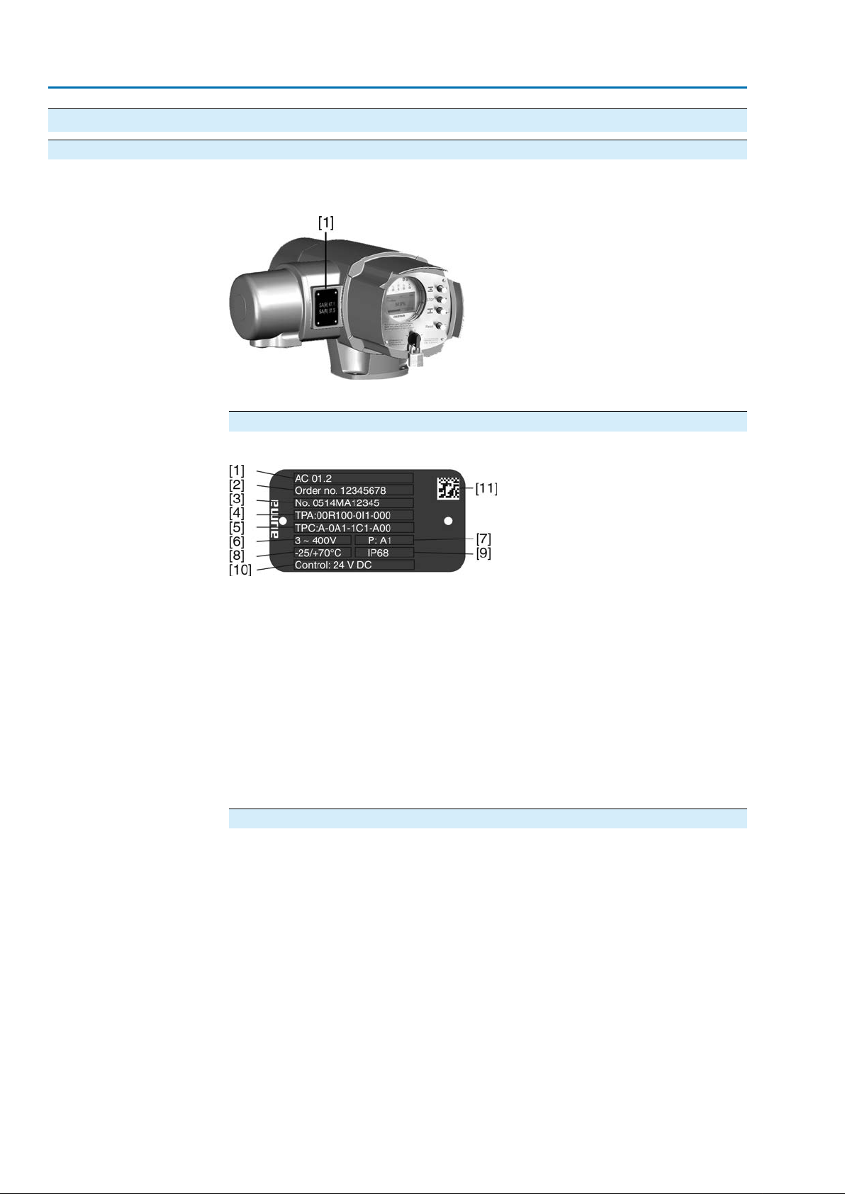
Each device is equipped with a name plate.
Figure 1: Arrangement of name plate
[1] Actuator controls name plate
Description of actuator controls name plate
Figure 2: Actuator controls name plate
Type designation
Order number
[1] Type designation
[2] Order number
[3] Serial number
[4] Actuator terminal plan
[5] Actuator controls terminal plan
[6] Mains voltage
[7] AUMA power class for switchgear
[8] Permissible ambient temperature
[9] Enclosure protection
[10] Control
[11] Data Matrix code
Descriptions
Type and size
These instructions apply to the following devices types and sizes:
Types: AC/ACExC = AUMATIC actuator controls
Size: 01.2
Versions: Intrusive and Non-Intrusive
The product can be identified using this number and the technical data as well as
order-related data pertaining to the device can be requested.
Please always state this number for any product inquiries.
On the Internet at http://www.auma.com, we offer a service allowing authorised
users to download order-related documents such as wiring diagrams and technical
data (both in German and English), inspection certificates and the operation
instructions when entering the order number.
10
Page 11
Actuator controls
AC 01.2/ACExC 01.2 Identification
Serial number
Actuator controls termin-
al plan
AUMA power class for
switchgear
Table 1: Description of serial number (with example)
MD123451405
Position 1+ 2: Assembly in week
Week 0505
Position 3 +4 :Year of production
Year of production: 201414
All other positions
Internal number for unambiguous product identificationMD12345
Position 9 in the TPA wiring diagram: Position transmitter (actuator):
Control unit: electromechanical:
0 = Without position transmitter
A, B, J, K, L, N = Potentiometer
C, D, E, G, H, M, S = EWG/RWG (electronic position transmitter)
Control unit: electronic:
I = MWG (Magnetic limit and torque transmitter)
The switchgear used in the actuator controls (reversing contactors/thyristors) are
classified according to AUMA power classes (e.g. A1, B1, ....).The power class
defines the max. permissible rated power (of the motor) the switchgear has been
designed for.The rated power (nominal power) of the actuator motor is indicated in
kW on the motor name plate. For the assignment of the A UMA pow er classes to the
nominal power of the motor types, refer to the separate electrical data sheets.
For switchgear without assignment to an y power classes, the actuator controls name
plate does not indicate the power class but the max. rated power in kW.
Control
Data Matrix code
2.2. Short description Actuator controls
Local con-
trols/AUMA CDT
Table 2: Control examples (indications on controls name plate)
DescriptionInput signal
24 V DC
115 V AC
Control voltage 24 V DC for OPEN - CLOSE control via digital inputs
(OPEN, STOP, CLOSE)
Control voltage 115 V AC f or OPEN - CLOSE control via digital inputs
(OPEN, STOP, CLOSE)
Input current for setpoint control via analog input0/4 – 20 mA
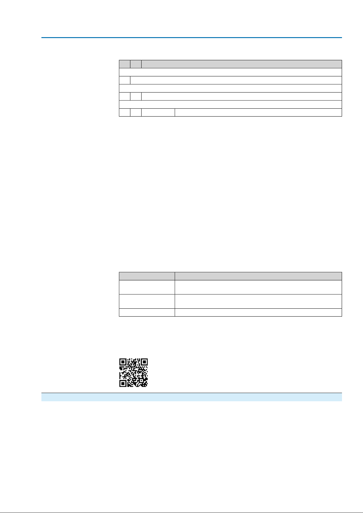
When registered as authorised user, you may use the AUMA Support App to scan
the Data Matrix code and directly access the order-related product documents without
having to enter order number or serial number.
Figure 3: Link to the App store:
AUMATIC actuator controls are used to operate AUMA actuators and are supplied
ready for use.The controls may be mounted directly to the actuator or separately
on a wall bracket.
The functions of the AUMATIC controls include standard valve control in OPEN CLOSE duty, positioning, process control, logging of operating data right through to
diagnostic functions.
Operation, setting, and display can be performed on site directly at the controls.
When set to local control, it is possible to
11
Page 12

Actuator controls
Identification AC 01.2/ACExC 01.2
●
operate the actuator via the local controls (push buttons and display) and perf orm
settings (contents of these instructions).
●
read in or out data or modify and save settings via the AUMA CDT software
(accessories), using a computer (laptop or PC).The connection between computer and AUMATIC is wireless via Bluetooth interface (not included in these
instructions).
Intrusive - Non-Intrusive
●
Intrusive version (control unit: electromechanical):
Limit and torque setting is performed via switches in the actuator.
●
Non-Intrusive version (control unit: electronic):
Limit and torque setting is performed via the controls, actuator and controls
housings do not have to be opened. For this purpose, the actuator is equipped
with an MWG (magnetic limit and torque transmitter), also supplying analogue
torque feedback signals/torque indication and analogue position feedback signals/position indication.
12
Page 13
Actuator controls
AC 01.2/ACExC 01.2 Operation
3. Operation
Valve damage due to incorrect basic setting!
→
Prior to electrical operation of the actuator, the basic settings i.e. type of seating,
torque and limit switching have to be completed.
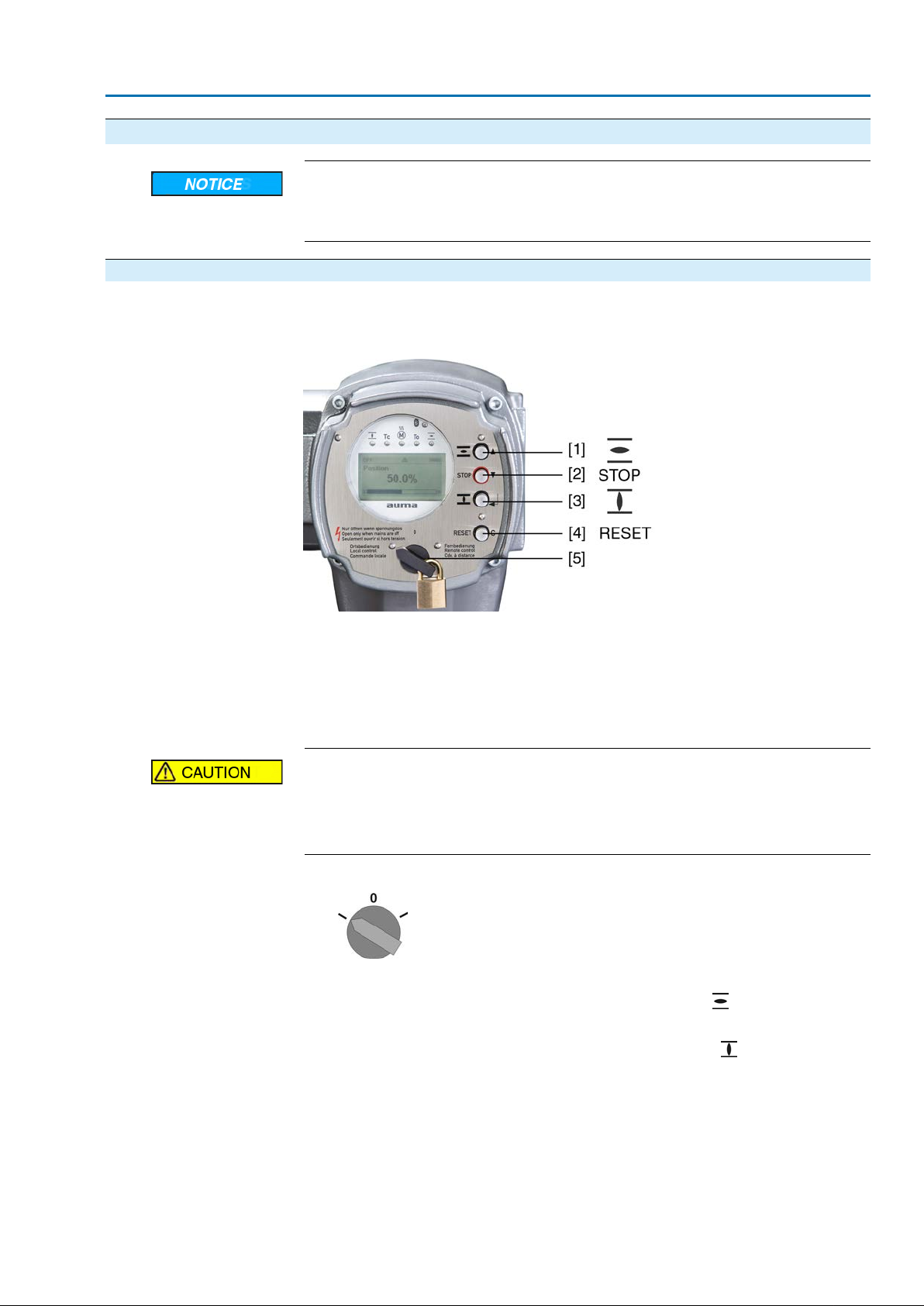
3.1. Local actuator operation
Local actuator operation is performed using the push buttons of the local controls of
the AC.
Figure 4: Local controls
[1] Push button for operation command in direction OPEN
[2] Push button STOP
[3] Push button for operation command in direction CLOSE
[4] Push button RESET
[5] Selector switch
Hot surfaces, e.g. possibly caused by high ambient temperatures or strong
direct sunlight!
Danger of burns
→
Check surface temperature and wear protective gloves, if required.
→
Set selector switch [5] to position Local control (LOCAL).
The actuator can now be operated using the push buttons [1 – 3]:
➥
-
Run actuator in direction OPEN: Press push button [1] .
- Stop actuator: Press push button STOP [2].
-
Run actuator in direction CLOSE: Press push button [3] .
Information The OPEN - CLOSE operation commands can be given either in push-to-run or in
self-retaining operation mode. For further information, please refer to <Push-to-run
operation or self-retaining local> chapter.
13
Page 14
Actuator controls
Operation AC 01.2/ACExC 01.2
3.2. Actuator operation from remote
→
Set selector switch to position Remote control (REMOTE).
Now, it is possible to operate the actuator via remote control, via operation
➥
commands (OPEN, STOP, CLOSE) or analogue setpoints (e.g. 0 – 20 mA).
Information For actuators equipped with a positioner , it is possible to change ov er between OPEN
- CLOSE control (Remote OPEN-CLOSE) and setpoint control (Remote SET-
POINT). For further information, refer to chapter <Change-over between OPEN CLOSE control and setpoint control>.
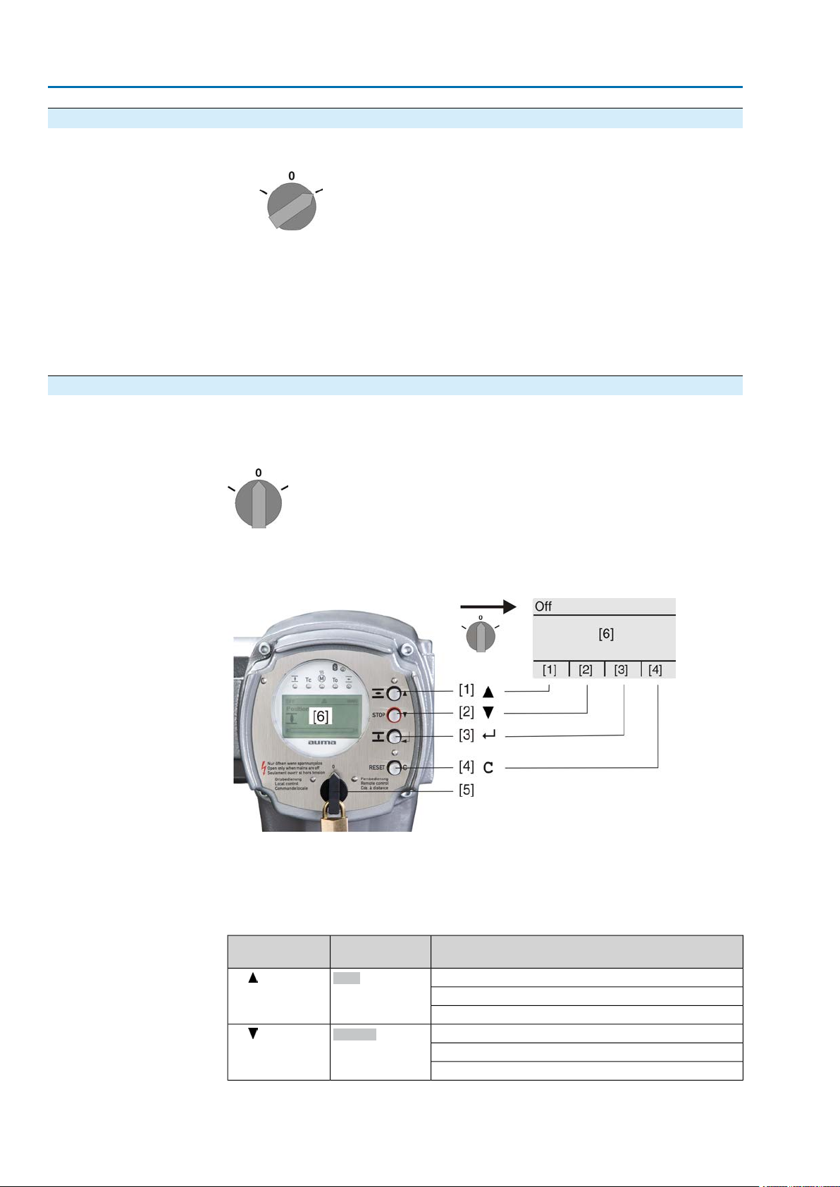
3.3. Menu navigation via push buttons (for settings and indications)
Menu navigation for display and setting is made via the push buttons [1 – 4] of the
local controls.
Set the selector switch [5] to position 0 (OFF) when navigating through the menu.
The bottom row of the display [6] serves as navigation support and explains which
push buttons [1 – 4] are used for menu navigation.
Figure 5:
[1–4] Push buttons or navigation support
[5] Selector switch
[6] Display
Table 3: Important push button functions for menu navigation
Push buttons
[1]
[2]
port on display
Up ▲
Down ▼
FunctionsNavigation sup-
Change screen/selection
Change values
Enter figures from 0 to 9
Change screen/selection
Change values
Enter figures from 0 to 9
14
Page 15

Actuator controls
AC 01.2/ACExC 01.2 Operation
Push buttons
[3]
[4] C
●
Backlight
The display is illuminated in white during normal operation.The backlight turns
to red under fault conditions.
●
The screen illumination is brighter when operating a push button. If no push
button is operated for 60 seconds, the display will become dim again.
3.3.1. Menu layout and navigation
Groups
The indications on the display are divided into 3 groups:
Figure 6: Groups
[1] Startup menu
[2] Status menu
[3] Main menu
port on display
Ok
Save
Edit
Details
Setup
Esc
FunctionsNavigation sup-
Confirm selection
Save
Enter <Edit> menu
Display more details
Enter Main menu
Cancel process
Return to previous display
ID
Group selection
Direct display via ID
Status menu and main menu are marked with an ID.
Figure 7: Marking with ID
S
ID starts with S = status menu
M
ID starts with M = main menu
It is possible to select between status menu S and main menu M:
For this, set selector switch to 0 (OFF), hold down push button C for approx. 2
seconds until a screen containing the ID M... appears.
Figure 8: Select menu groups
You return to the status menu if:
●
the push buttons on the local controls have not been oper ated within 10 minutes
●
or by briefly pressing C
When entering the ID within the main menu, screens can be displayed directly (without
clicking through).
15
Page 16

Actuator controls
Operation AC 01.2/ACExC 01.2
Figure 9: Direct display (example)
Display indicates in the bottom row:Go to
1.
Press push button Go to.
Display indicates:Go to menu M0000
2.
Use push buttons Up ▲ Down ▼ to select figures 0 to 9.
3.
Press push button Ok to confirm first digit.
4. Repeat steps 2 and 3 for all further digits.
5.
To cancel the process: Press C Esc.
3.4. User level, password User level
Password
The user level defines which menu items or par ameters can be displayed or modified
by the active user.
There are 6 different user levels.The user level is indicated in the top row:
Figure 10: User level display (example)
A password must be entered to allow par ameter modification.The display indicates:
Password 0***
A specific password is assigned to each user level and permits different actions.
Table 4: User levels and authorisations
Authorisation/passwordDesignation (user level)
Observer (1)
Operator (2)
Maintenance (3)
Specialist (4)
Service (5)
AUMA (6)
Verify settings
No password required
Change settings
Default factory password: 0000
Reserved for future extensions
Change device configuration
e.g. type of seating, assignment of output contacts
Default factory password: 0000
Service staff
Change configuration settings
AUMA administrator
3.4.1. Password entry
16
1.
Select desired menu and hold down push button for approx. 3 seconds.
Display indicates the set user level, e.g Observer (1)
➥
2.
Press Up ▲to select a higher user level and press Ok to confirm.
Display shows:Password 0***
➥
3.
Use push buttons Up ▲ Down ▼ to select figures 0 to 9.
4.
Confirm first digit of password via push button Ok.
5. Repeat steps 1 and 2 for all further digits.
Having confirmed the last digit with Ok, access to all parameters within one
➥
user level is possible if the password entry is correct.
Page 17

Actuator controls
AC 01.2/ACExC 01.2 Operation
3.4.2. Password change
Only the passwords of same or lower user level may be changed.
Example:The user is signed in as Specialist (4).This authorises him or her to modify
the passwords between user levels (1) to (4).
Device configuration M0053
Service functions M0222
Change passwords M0229
Menu point Service functions M0222 is only visible if user level has been set to
Specialist (4) or higher.
Select main menu
Change passwords
1. Set selector switch to position 0 (OFF).
2.
Press push button C Setup and hold it down for approx. 3 seconds.
Display goes to main menu and indicates:▶ Display...
➥
3.
Select parameter Change passwords either:
→
→
-
Display indicates:▶ Change passwords
- The user level is indicated in the top row (1 – 6), e.g.:
- For user level 1 (view only), passwords cannot be changed.To change passwords, you must change to a higher user level. For this, enter a password via
a parameter.
4.
For a user level between 2 and 6: Press push button Ok.
The display indicates the highest user level, e.g.:For user 4
➥
5.
Select user level via push buttons Up ▲ Down ▼ and confirm with Ok.
Display indicates:▶ Change passwords Password 0***
➥
6.
Enter current password (→ enter password).
Display indicates:▶ Change passwords Password (new) 0***
➥
7.
Enter new password (→ enter password).
Display indicates:▶ Change passwords For user 4 (example)
➥
8.
Select next user lev el via push b uttons Up ▲ Down ▼ or cancel the process
via Esc.
click via the menu to parameter, or
via direct display: press and enter ID M0229
3.5. Language in the display
The AUMATIC display is multilingual.
3.5.1. Language change
Display... M0009
Language M0049
Select main menu
1. Set selector switch to position 0 (OFF).
17
Page 18

Actuator controls
Operation AC 01.2/ACExC 01.2
2.
Press push button C Setup and hold it down for approx. 3 seconds.
Display goes to main menu and indicates:▶ Display...
➥
3.
Change language
Press Ok.
Display indicates:▶ Language
➥
4.
Press Ok.
Display indicates the selected language, e.g.:▶ Deutsch
➥
5. The bottom row of the display indicates:
Language selection
→
→
6.
Press Edit.
Display indicates:▶ Observer (1)
➥
7.
Select user level via Up ▲ Down ▼ resulting in the following significations:
→
→
8.
Press Ok.
Display indicates:Password 0***
➥
9.
Enter password (→ enter password).
Display indicates:▶ Language and Save (bottom row)
➥
10.
Select new language via Up ▲ Down ▼ resulting in the following significa-
Save → continue with step 10
Edit → continue with step 6
black triangle:▶ = current setting
white triangle: ▷ = selection (not saved yet)
tions:
→
→
11.
Confirm selection via Save.
The display changes to the new language.The new language selection is saved.
➥
black triangle:▶ = current setting
white triangle: ▷ = selection (not saved yet)
18
Page 19
Actuator controls
AC 01.2/ACExC 01.2 Indications
4. Indications
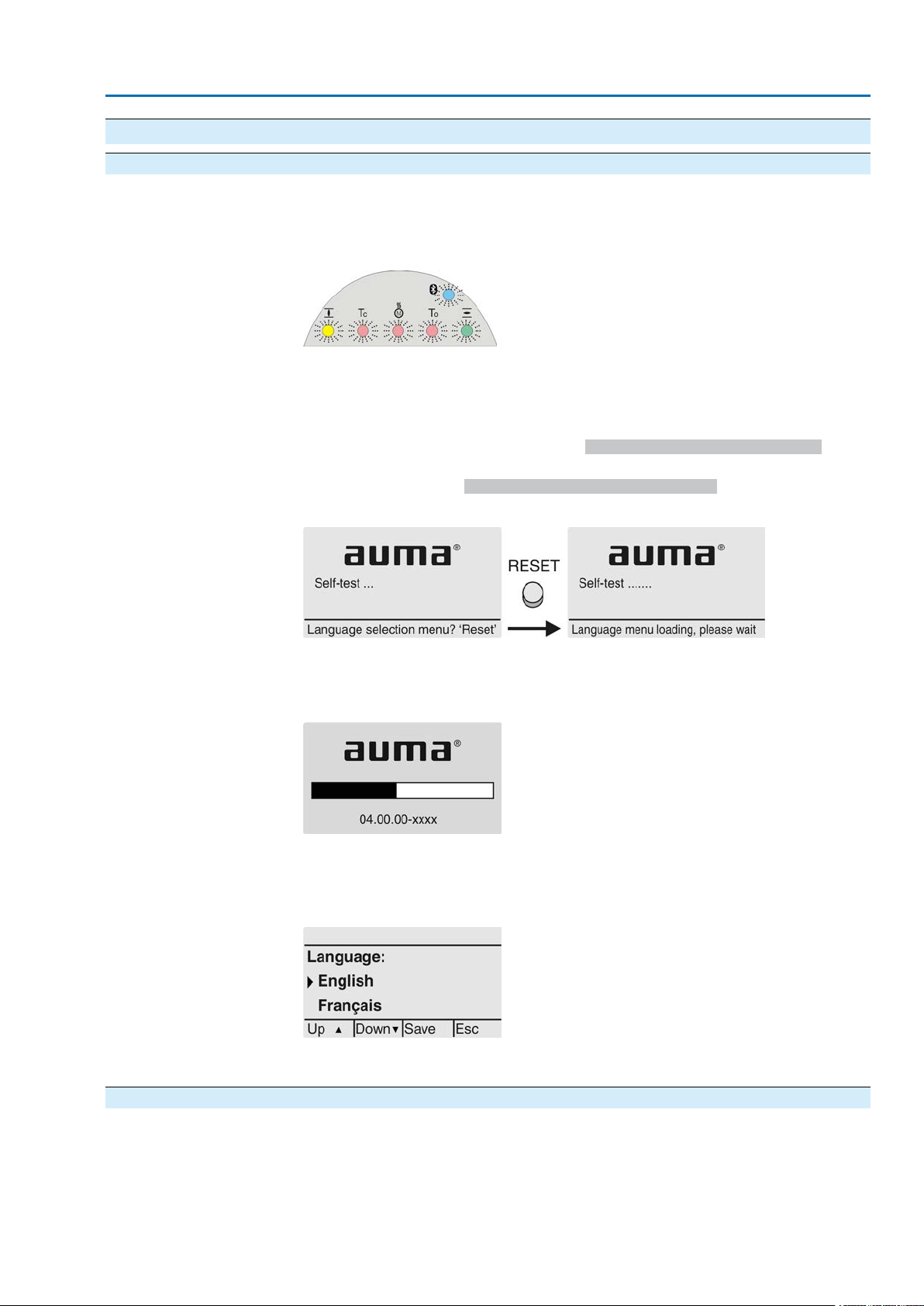
4.1. Indications during commissioning LED test
Language selection
When switching on the power supply, all LEDs on the local controls illuminate for
approx. 1 second.This optical feedback indicates that the v oltage supply is connected
to the controls and all LEDs are operable.
Figure 11: LED test
During the self-test, the language selection can be activated so that the selected
language is immediately indicated in the display. For this, set selector switch [5] to
position 0 (OFF).
Activate language selection:
1.
Display indicates in the bottom row:Language selection menu? 'Reset'
2. Press push button RESET and hold it down until the following te xt is displayed
in the bottom line: Language menu loading, please wait.
Figure 12: Self-test
The language selection menu follows the startup menu.
Startup menu
The current firmware version is displayed during the startup procedure:
Figure 13: Startup menu with firmware version: 04.00.00–xxxx
If the language selection feature has been activated during the self-test, the menu
for selecting the display language will now be indicated. For further information on
language setting, please refer to chapter <Language in the display>.
Figure 14: Language selection
If no entry is made over a longer period of time (approx. 1 minute), the display
automatically returns to the first status indication.
4.2. Indications in the display Status bar
The status bar (first row in the display) indicates the operation mode [1], the presence
of an error [2] and the ID number [3] of the current display indication.
19
Page 20
Actuator controls
Indications AC 01.2/ACExC 01.2
Figure 15: Information in the status bar (top)
[1] Operation mode
[2] Error symbol (only for faults and warnings)
[3] ID number: S = Status page
Navigation support
If further details or information are available with reference to the displa y, the following
indications Details or More appear in the navigation support (bottom display row).
Then, further information can be displayed via the push button.
Figure 16: Navigation support (bottom)
[1] shows list with detailed indications
[2] shows further available information
The navigation support (bottom row) is faded out after approx. 3 seconds. Press any
push button (selector switch in position 0 (OFF)) to fade in the navigation support.
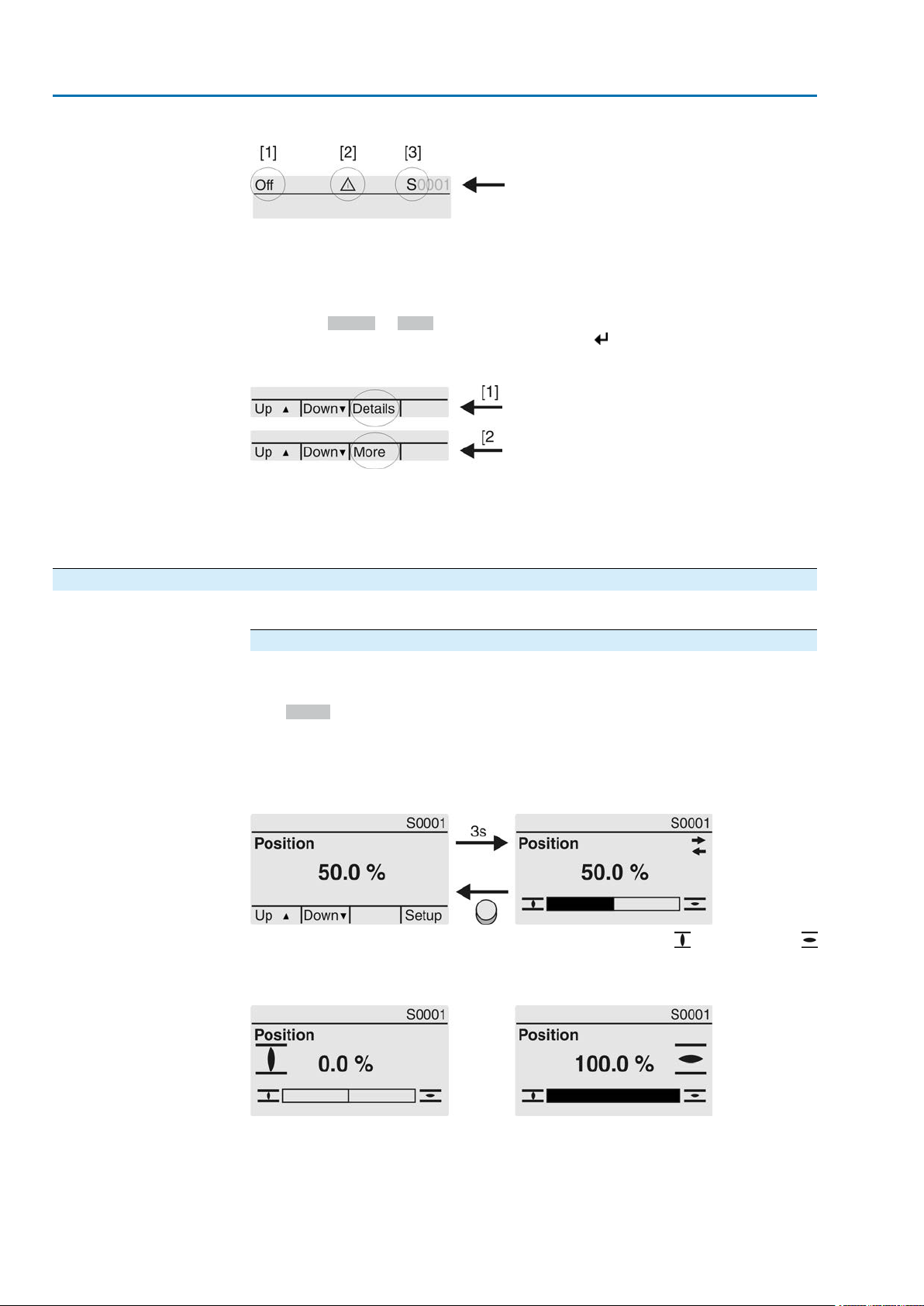
4.2.1. Feedback indications from actuator and valve
Display indications depend on the actuator version.
Valve position (S0001)
This indication is only available if a position transmitter (potentiometer, EWG, RWG
or MWG) is installed in the actuator.
●
S0001 on the display indicates the valve position in % of the travel.
●
The bargraph display appears after approx. 3 seconds.
●
When issuing an operation command, an arrow indicates the direction
(OPEN/CLOSE).
Figure 17:Valve position and direction of operation
Reaching the preset end positions is additionally indicated via (CLOSED) and
(OPEN) symbols.
Figure 18: End position CLOSED/OPEN reached
0% Actuator is in end position CLOSED
100% Actuator is in end position OPEN
20
Page 21
Actuator controls
AC 01.2/ACExC 01.2 Indications
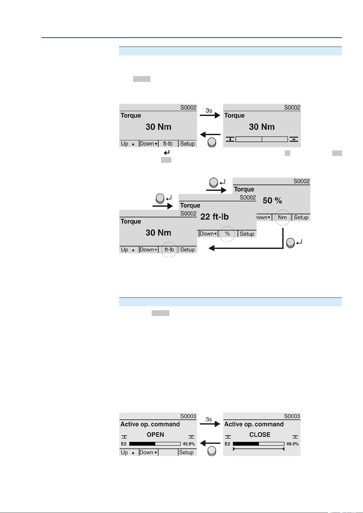
Torque (S0002)
The indication is only available if the actuator is equipped with an MWG (magnetic
limit and torque transmitter).
●
S0002 on the display indicates the torque applied at the actuator output.
●
The bargraph display appears after approx. 3 seconds.
Figure 19:Torque
Select unit
Display in percent
OPEN - CLOSE control
The push button allows to select the unit displayed (percent %, Newton metre Nm
or "foot-pound" ft-lb
Figure 20: Units of torque
100 % indication equals the max. torque indicated on the name plate of the actuator .
Example: SA 07.6 with 20 – 60 Nm.
●
100 % corresponds to 60 Nm of nominal torque.
●
50 % corresponds to 30 Nm of nominal torque.
Operation commands (S0003)
The display S0003 indicates:
●
active operation commands, lik e e.g.: Operation in direction CLOSE or in direction OPEN
●
the actual value E2 as bargraph indication and as v alue between 0 and 100 %.
●
for setpoint control (positioner): setpoint E1
●
for stepping mode or for intermediate positions with operation profile: pivot
points and operation behaviour of pivot points
The navigation support (bottom row) is faded out after approx. 3 seconds and the
axis/axes for pivot point display are shown.
Active operation commands (OPEN, CLOSE, ...) are shown above the bargraph
display. The figure below shows the operation command in direction CLOSE.
Figure 21: Display for OPEN - CLOSE control
E2 Actual position value
21
Page 22

Actuator controls
Indications AC 01.2/ACExC 01.2
Setpoint control
Pivot point axis
If the positioner is enabled and activated, the bargraph indication for E1 (position
setpoint) is displayed.
The direction of the operation command is displayed b y an arrow above the barg raph
indication.The figure below shows the operation command in direction CLOSE.
Figure 22: Indication for setpoint control (positioner)
E1 Position setpoint
E2 Actual position value
The pivot points and their operation behaviour (operation profile) are shown on the
pivot point axis by means of symbols.
The symbols are only displayed if at least one of the f ollo wing functions is activ ated:
Operation profile M0294
Timer CLOSE M0156
Timer OPEN M0206
Figure 23: Examples: on the left pivot points (intermediate positions); on the right
stepping mode
Table 5: Symbols along the pivot point axis
Symbol
with operation profile
Stop during operation in direction
CLOSE
Stop during operation in direction
OPEN
OPEN and CLOSE
and CLOSE
Stepping modePivot point (intermediate position)
End of stepping modePivot point without reaction|
Start of stepping mode in direction
CLOSE
Start of stepping mode in direction
OPEN
–Stop during operation in directions
–Pause for oper ation in direction CLOSE
–Pause for oper ation in direction OPEN
–Pause for oper ation in directions OPEN
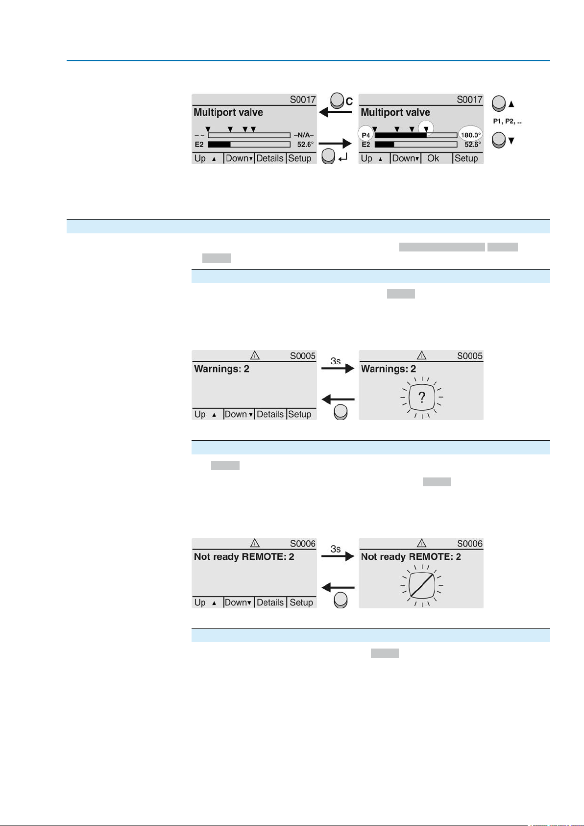
Multiport valve positions (S0017)
In case of active multiport valve function, the display S0017 indicates a second
bargraph display with set positions (valve connections) above the actual position
value E2. Positions (P1, P2, ...) are displayed with a black triangle . Push buttons
are used to select positions. Both positions and the actual position v alue E2 are
displayed in degrees.
22
Page 23
Actuator controls
AC 01.2/ACExC 01.2 Indications
Figure 24: Status indication for multiport valve (example P4 = 180°)
P (P1, P2, ...) selected position (1, 2, ...)
(– –) no position selected
E2 Actual position value
4.2.2. Status indications according to AUMA classification
These indications are available if the parameter Diagnostic classific. M0539 is set
to AUMA.
Warnings (S0005)
If a warning has occurred, the display shows S0005:
●
the number of warnings occurred
●
a blinking question mark after approx. 3 seconds
Figure 25:Warnings
For further information, please also refer to <Corrective action>.
Not ready REMOTE (S0006)
The S0006 display shows indications of the Not ready REMOTE group.
If such an indication has occurred, the display shows S0006:
●
the number of indications occurred
●
a blinking crossbar after approx. 3 seconds
Figure 26: Not ready REMOTE indications
For further information, please also refer to <Corrective action>.
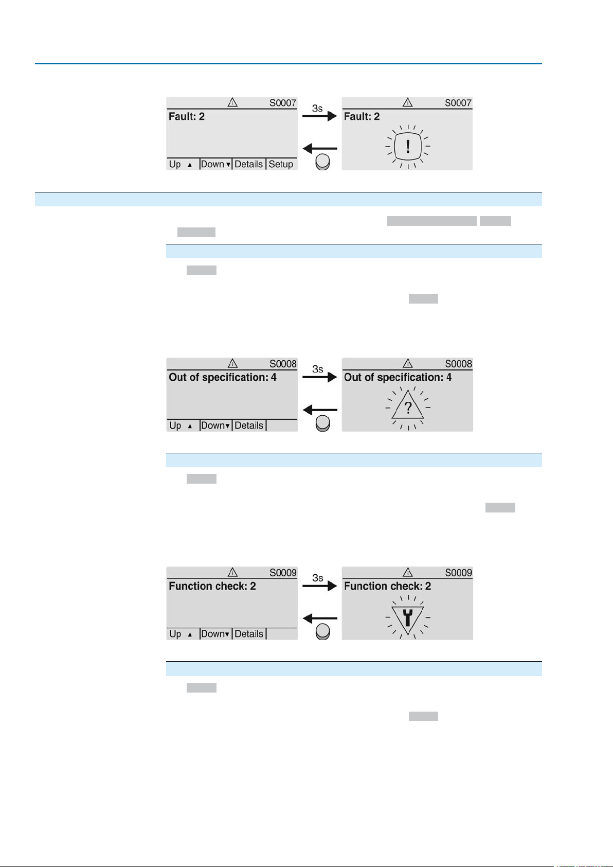
Fault (S0007)
If a fault has occurred, the display shows S0007:
●
the number of faults occurred
●
a blinking exclamation mark after approx. 3 seconds
23
Page 24
Actuator controls
Indications AC 01.2/ACExC 01.2
Figure 27: Fault
For further information, please also refer to <Corrective action>.
4.2.3. Status indications according to NAMUR recommendation
These indications are available, if the parameter Diagnostic classific. M0539 is set
to NAMUR.
Out of Specification (S0008)
The S0008 indication shows out of specification indications according to NAMUR
recommendation NE 107.
If such an indication has occurred, the display shows S0008:
●
the number of indications occurred
●
a blinking triangle with question mark after approx. 3 seconds
Figure 28: Out of specification
For further information, please also refer to <Corrective action>.
Function check (S0009)
The S0009 indication shows function check indications according to NAMUR
recommendation NE 107.
If an indication has occurred via the function check, the display shows S0009:
●
the number of indications occurred
●
a blinking triangle with a spanner after approx. 3 seconds
Figure 29: Function check
For further information, please also refer to <Corrective action>.
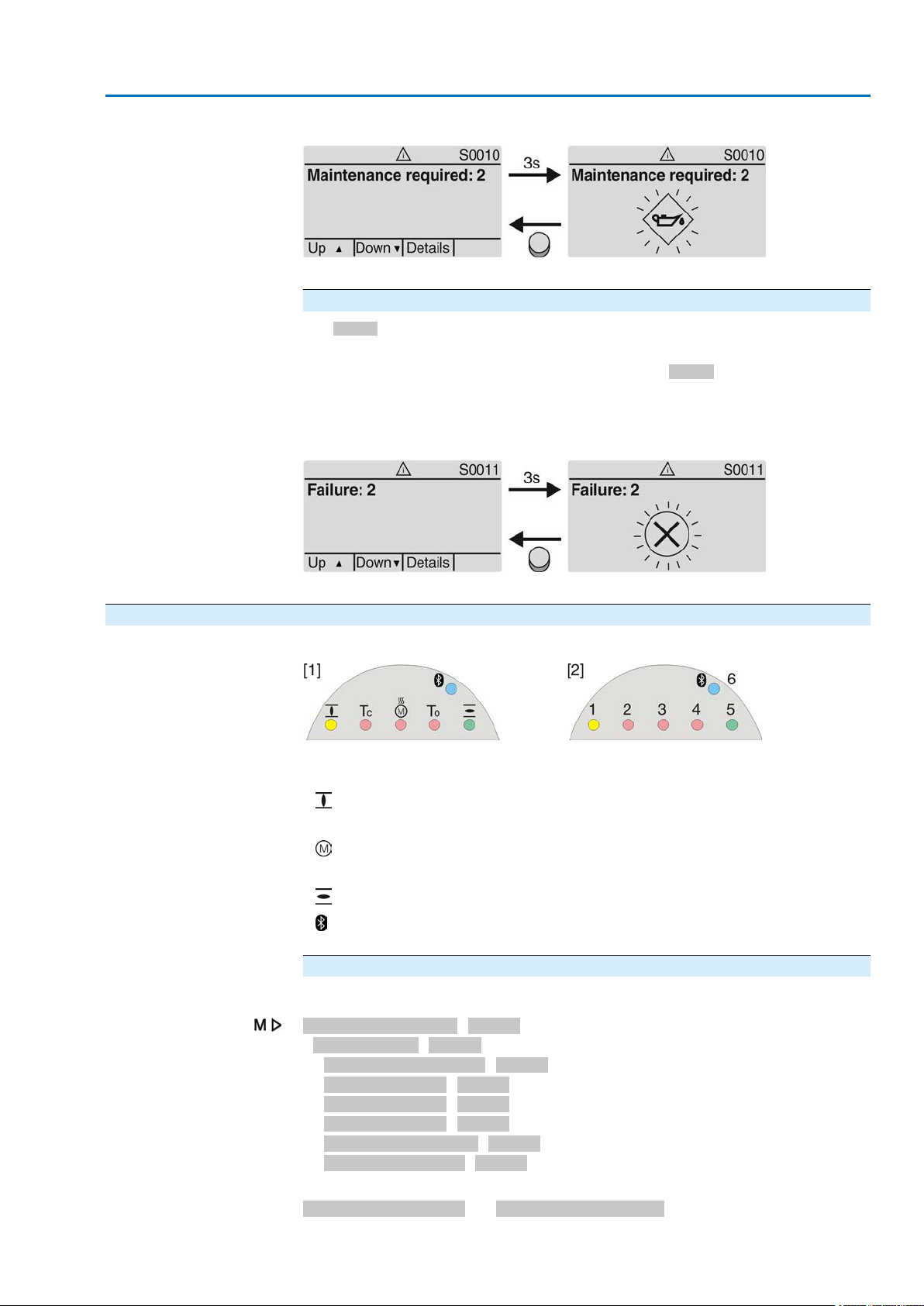
Maintenance required (S0010)
The S0010 indication shows maintenance indications according to NAMUR
recommendation NE 107.
If such an indication has occurred, the display shows S0010:
●
the number of indications occurred
●
a blinking square with an oil can after approx. 3 seconds
24
Page 25
Actuator controls
AC 01.2/ACExC 01.2 Indications
Figure 30: Maintenance required
For further information, please also refer to <Corrective action>.
Failure (S0011)
The S0011 indication shows the causes of the failure indication according to NAMUR
recommendation NE 107.
If such an indication has occurred, the display shows S0011:
●
the number of indications occurred
●
a blinking circle with a cross after approx. 3 seconds
Figure 31: Failure
For further information, please also refer to <Corrective action>.
4.3. Indication lights of local controls
Figure 32: Arrangement and signification of indication lights
[1] Marking with symbols (standard)
[2] Marking with figures 1 – 6 (option)
End position CLOSED reached (blinking: operation in direction CLOSE)
1
2 Tc Torque fault CLOSE
Motor protection tripped
3
4 To Torque fault OPEN
End position OPEN reached (blinking: operation in direction OPEN)
5
Bluetooth connection
6
Modify indication light assignment (indications)
Different indications can be assigned to LEDs 1 – 5.
Device configuration M0053
Local controls M0159
Indication light 1 (left) M0093
Indication light 2 M0094
Indication light 3 M0095
Indication light 4 M0096
Indicat. light 5 (right) M0097
Signal interm. pos. M0167
Defaut values (Europe):
Indication light 1 (left) = End p. CLOSED, blink
25
Page 26

Actuator controls
Indications AC 01.2/ACExC 01.2
Indication light 2 = Torque fault CLOSE
Indication light 3 = Thermal fault
Indication light 4 = Torque fault OPEN
Indicat. light 5 (right) = End p. OPEN, blink
Signal interm. pos. = OPEN/CLOSED = Off
Further setting values:
Refer to <Appendix>/<Selection overview for output contacts and indication lights>
4.3.1. Indication lights: change colour — Option —
User level required to make changes: AUMA (6)
Device configuration M0053
Local controls M0159
Setting valuesDefault values for versionMenuParameters
USAEurope
GreenYellowM0838Colour ind.light 1
BlueRedM0839Colour ind.light 2
YellowRedM0840Colour ind.light 3
BlueRedM0841Colour ind.light 4
RedGreenM0842Colour ind.light 5
Yellow
Green
Yellow/green
Red
Blue
Purple
Red
Yellow
Orange
Red
Blue
Purple
Green
Red
Orange
26
Page 27

Actuator controls
AC 01.2/ACExC 01.2 Signals (output signals)
5. Signals (output signals)
5.1. Status signals via output contacts (digital outputs) Characteristics
5.1.1. Assignment of outputs
Output contacts are used to send status signals (e.g. reaching the end positions,
selector switch position, faults...) as binary signals to the control room.
Status signals only have two states: active or inactive. Active means that the
conditions for the signal are fulfilled.
The output contacts (outputs DOUT 1 – 12) can be assigned to various signals.
Required user level:Specialist (4) or higher.
Device configuration M0053
I/O interface M0139
Digital outputs M0110
Default values:
Signal DOUT 1 = Fault
Signal DOUT 2 = End position CLOSED
Signal DOUT 3 = End position OPEN
Signal DOUT 4 = Selector sw. REMOTE
Signal DOUT 5 = Torque fault CLOSE
Signal DOUT 6 = Torque fault OPEN
Signal DOUT 7 = End position CLOSED
Signal DOUT 8 = End position OPEN
Signal DOUT 9 = Selector sw. REMOTE
Signal DOUT 10 = Torque fault CLOSE
Signal DOUT 11 = Torque fault OPEN
Signal DOUT 12 = Fault
Signal DOUT 1 M0109
Further setting values:
Refer to <Appendix>/<Selection overview for output contacts and indication lights>
5.1.2. Coding the outputs
The output signals DOUT 1 – 12 can be set either to high active or low active.
●
High active = output contact closed = signal active
●
Low active = output contact open = signal active
Required user level:Specialist (4) or higher.
Device configuration M0053
I/O interface M0139
Digital outputs M0110
Coding DOUT 1 M0102
Default values for DOUT 1 – 12: High active
5.2. Configurable status signals
The signals described here are collective signals of various other signals which can
be configured for specific users. For configuration, the individual signals can be
selected from a list and activated (☑) or deactivated (☐) indivdually.The signals can
either be assigned to a digital output (output contact) or to an indication light (LED).
For detailed information on these signals, refer to <Fault signals and warnings>
chapter.
Configure status signals
Required user level:Specialist (4) or higher.
27
Page 28

Actuator controls
Signals (output signals) AC 01.2/ACExC 01.2
Device configuration M0053
Config. of signals M0860
Failure (configurable) M0879
Fault (Cfg) M0880
Warnings (Cfg) M0881
Not ready REMOTE (Cfg) M0882
Default values Failure (configurable):
☑ = activated
☑ Fault (Cfg)
☑ Warning (Cfg)
☑ Not ready REMOTE (Cfg)
Default values Fault (Cfg):
☑ = activated
☑ Configuration error
☑ Config. error REMOTE
☑ Internal error
☑ Torque fault CLOSE
☑ Torque fault OPEN
☑ Phase fault
☑ Incorrect phase seq
☑ Mains quality
☑ Thermal fault
☑ Fault no reaction
Default values Warnings (Cfg):
☑ = activated
☑ Config. warning
☑ Internal warning
☑ Wrn input AIN 1
☑ Wrn input AIN 2
☑ Wrn setpoint position
☑ Not used
☑ Maintenance required
Default values Not ready REMOTE (Cfg):
☑ = activated
☑ Wrong oper. cmd
☑ Sel. sw. not REMOTE
☑ Service active
☑ Disabled
☑ EMCY stop active
☑ EMCY behav. active
☑ I/O interface
☑ Handwheel active
☑ FailState fieldbus
☑ Local STOP
28
Page 29

Actuator controls
AC 01.2/ACExC 01.2 Signals (output signals)
☑ Interlock by-pass
☑ PVST active
5.3. Analogue signals (analogue outputs) Conditions
Characteristics
5.3.1. Assignment of analogue output 1
The actuator is equipped with a position transmitter.
Depending on the actuator equipment, different signals, such as travel, torque or
output speed can be recorded and issued as continuous values, e.g. 4 to 20 mA.
The AC is equipped with up to two analogue outputs AOUT1 and AOUT2.
Designation in the wiring diagram: AOUT 1.
Required user level:AUMA (6).
Device configuration M0053
I/O interface M0139
Analogue outputs M0335
Signal AOUT 1 M0131
Default value: Actual position
Information The signal range of the output (e.g. 0/4 – 20 mA) is set via a separate parameter
(Signal range AOUT1 M0129).
Setting values:
Not used
Actual position
Torque
Analogue output 1 is not assigned.
Position feedback of the valve position (actual position value E2)
Condition: Position transmitter installed in the actuator.
An adjustment to the end positions or the defined travel is not required. An automatic
adjustment is done via the end positions (LSC (WSR) and LSO (WOEL)).
For torque seating, the end positions OPEN and CLOSED of the limit switching
should be set as close as possible to the end positions of the valve to minimise the
deviation of the feedback.
Torque feedback E6
Condition: MWG position transmitter in actuator.
The zero point is in the centre of the selected output range (10 mA or 12 mA).The
torque in direction CLOSE is indicated with 0 – 10 mA or 4 – 12 mA, the torque in
direction OPEN with 10 – 20 mA or 12 – 20 mA. F or 127 % of the maxim um nominal
output torque, 0 or 4 mA are indicated in direction CLOSE, and 20 mA are indicated
in direction OPEN.
Input AIN 1
Input AIN 2
Figure 33: Actual torque value
–127 %= maximum nominal torque in end position CLOSED reached
+127 %= maximum nominal torque in end position OPEN reached
Analogue value transmitted via AIN1 (refer to wiring diagram) to the actuator.
Condition: An analogue signal (e.g. 0 – 20 mA) is connected to the analogue input
AIN 1.
Analogue value transmitted via AIN 2 (refer to wiring diagram) to the actuator.
29
Page 30

Actuator controls
Signals (output signals) AC 01.2/ACExC 01.2
Condition: An analogue signal (e.g. 0 – 20 mA) is connected to the analogue input
AIN 2.
Speed target value
5.3.2. Signal range of analogue output 1
Actual speed value.
Required user level:Specialist (4) or higher.
Device configuration M0053
I/O interface M0139
Analogue outputs M0335
Signal range AOUT1 M0129
Default value: 0 - 20 mA
Setting values:
0 - 20 mA
4 - 20 mA
20 - 0 mA
20 - 4 mA
5.3.3. Adjustment of analogue output 1
Analogue output 1 generates a 0 – 20 mA signal.
Analogue output 1 generates a 4 – 20 mA signal.
Analogue output 1 generates a 20 – 0 mA signal.
Analogue output 1 generates a 20 – 4 mA signal.
The initial values and end values of the signal range can be corrected by ± 1 mA.
Example: Parameter Signal range AOUT1 = 4 - 20 mA
The initial value (4 mA) can be adapted within a range of 3 mA to 5 mA.
The end value (20 mA) can be adapted within a range of 19 mA to 21 mA.
Required user level:Specialist (4) or higher.
Device configuration M0053
I/O interface M0139
Analogue outputs M0335
Adjustment AOUT 1 M0544
0/4 mA (initial value) M0140
20 mA (final value) M0210
Default value: 0
Setting ranges: –100 ... 100 (– 1.00 to + 1.00 mA)
5.3.4. Assignment of analogue output 2
Designation in the wiring diagram: AOUT2.
Required user level:AUMA (6).
Device configuration M0053
I/O interface M0139
Analogue outputs M0335
Signal AOUT 2 M0132
Default value: Torque
Setting values:
Description see <Assignment of analogue output 1>.
5.3.5. Signal range of analogue output 2
Required user level:Specialist (4) or higher.
Device configuration M0053
I/O interface M0139
Analogue outputs M0335
Signal range AOUT2 M0130
30
Page 31

Actuator controls
AC 01.2/ACExC 01.2 Signals (output signals)
Default value: 0 - 20 mA
Setting values:
0 - 20 mA
4 - 20 mA
20 - 0 mA
20 - 4 mA
5.3.6. Adjustment of analogue output 2
Analogue output 2 generates a 0 – 20 mA signal.
Analogue output 2 generates a 4 – 20 mA signal.
Analogue output 2 generates a 20 – 0 mA signal.
Analogue output 2 generates a 20 – 4 mA signal.
Initial values and end values of the signal range can be corrected by ± 1 mA
Example: Parameter Signal range AOUT1 = 4 - 20 mA
The initial value (4 mA) can be adapted within a range of 3 mA to 5 mA.
The end value (20 mA) can be adapted within a range of 19 mA to 21 mA.
Required user level:Specialist (4) or higer.
Device configuration M0053
I/O interface M0139
Analogue outputs M0335
Adjustment AOUT 2 M0545
0/4 mA (initial value) M0141
20 mA (final value) M0211
Default values: 0
Setting ranges: –100 ... 100 (–1.00 to +1.00 mA)
31
Page 32

Actuator controls
Operation AC 01.2/ACExC 01.2
6. Operation
Different operation modes (states) are available.The current operation mode is
indicated in the first line of the display:
Figure 34: Example: Operation mode Off
This chapter describes the characteristics of the different operation modes; the
respective functions are described in separate chapters.
6.1. Operation mode Off
The selector switch is in position 0 (OFF).
●
Characteristics
The indication in the top row of the display shows:Off
●
Electric operation is not possible (not even EMERGENCY operation).
●
The controls remain fully operative as far as signalling is concerned (controls’
power supply is maintained).
●
Push buttons C can be used for menu navigation via the display.
6.2. Operation mode Local
Selector switch is in position Local control (LOCAL).
●
Characteristics
The indication in the top row of the display shows:Local
●
In motor operation, the actuator can be controlled locally via the push buttons
(OPEN), STOP, (CLOSE).
●
Faults and warnings without automatic reset can be confirmed with the push
button RESET.
6.2.1. Push-to-run operation or self-retaining Local
Parameter Self-retaining Local M0076 determines the actuator operation behaviour
to operation commands via push buttons on local controls.
Customer settings M0041
Local controls M0075
Self-retaining Local M0076
Default value: OPEN and CLOSE
Setting values:
Off (push-to-run op.)
OPEN
CLOSE
Push-to-run operation activated, self-retaining off:
Actuator only runs in direction OPEN or CLOSE while an operation command is
being received.The actuator stops if the operation command is cancelled.
In direction OPEN = self-retaining (in direction CLOSE push-to-run operation):
After an operation command in direction OPEN, the actuator continues to run, even
if the operation command is cancelled (self-retaining).The actuator is either stopped
by the STOP command or if end position OPEN or an intermediate position OPEN
has been reached.
In direction CLOSE = self-retaining (in direction OPEN push-to-run operation):
32
Page 33

Actuator controls
AC 01.2/ACExC 01.2 Operation
After an operation command in direction CLOSE, the actuator continues to run, even
if the operation command is cancelled (self-retaining).The actuator is either stopped
by the STOP command or if end position CLOSED or an intermediate position CLOSE
has been reached.
OPEN and CLOSE
In directions OPEN and CLOSE = self-retaining:
After an operation command, the actuator continues to run in directions OPEN or
CLOSE, even if the operation command is cancelled (self-retaining).The actuator
is either stopped by the STOP command or if an end position or intermediate position
has been reached.
Direct reversal of operation is not possib le. Operation commands in directions OPEN
or CLOSE must be stopped first by STOP command. Only then is an operation
command into the opposite direction allowed.
OPEN & CL w/o STOP
In directions OPEN and CLOSE = self-retaining without stop:
Direct reversal of operation is also possible without the STOP command. However,
operation can be stopped at any time by the STOP command.
Information
Hold down push buttons (OPEN) or (CLOSE) for more than 2 seconds to activate self-retaining, press STOP to reset the operation mode to push-to-run operation.
6.3. Operation mode Remote
Selector switch is in position Remote control (REMOTE).
Characteristics
The indication in the top row of the display shows the set source of the operation
commands:
●
Remote (parallel interface)
●
Remote II (parallel interface, push button station)
Depending on the control, a distinction is made between:
●
OPEN - CLOSE control (operation mode Remote OPEN - CLOSE):
Control is made via binary operation commands OPEN, STOP, CLOSE.
(or for activated Multiport Valve function via operation commands CW, CCW)
●
Setpoint control (operation mode Remote SETPOINT):
Control via analogue operation commands, e.g. 4 – 20 mA.
●
Information
Binary signals (e. g. +24 V DC) via digital inputs are only recognised as valid
operation commands if the signal is present for at least 10 ms.
●
If a positioner or process controller is available, change-over between OPEN CLOSE control (operation mode Remote OPEN - CLOSE) and setpoint control
(operation mode Remote SETPOINT) is possible. Refer to chapter <Changeover between OPEN - CLOSE control and setpoint control>.
6.3.1. Push-to-run operation or self-retaining Remote
Parameters Self-retaining Remote M0100, Self-retaining M01193 and Self-retaining
Remote II M0101 determine the actuator operation behaviour to binary operation
commands (OPEN, STOP, CLOSE or CW, CCW), which control the actuator “from
Remote” via I/O interface.
Customer settings M0041
I/O interface M0015
Self-retaining Remote M0100
Self-retaining M01193
Self-retaining Remote II M0101
Default values:
33
Page 34

Actuator controls
Operation AC 01.2/ACExC 01.2
Self-retaining = Off (push-to-run op.)
Self-retaining Remote II = OPEN and CLOSE
Setting values for parameters,Self-retaining Remote M0100 and Self-retaining
Remote II M0101:
Off (push-to-run op.)
Push-to-run operation activated, self-retaining off:
Actuator only runs in directions OPEN or CLOSE while an operation command is
being received.The actuator stops if the operation command is cancelled.
OPEN
In direction OPEN = self-retaining (in direction CLOSE push-to-run operation):
After an operation command in direction OPEN, the actuator continues to run, even
if the operation command is cancelled (self-retaining).The actuator is either stopped
by the STOP command or if end position OPEN or an intermediate position OPEN
has been reached.
CLOSE
In direction CLOSE = self-retaining (in direction OPEN push-to-run operation):
After an operation command in direction CLOSE, the actuator continues to run, even
if the operation command is cancelled (self-retaining).The actuator is either stopped
by the STOP command or if end position CLOSED or an intermediate position
CLOSED has been reached.
OPEN and CLOSE
In directions OPEN and CLOSE = self-retaining:
After an operation command, the actuator continues to run in directions OPEN or
CLOSE, even if the operation command is cancelled (self-retaining).The actuator
is either stopped by the STOP command or if an end position or intermediate position
has been reached.
Direct reversal of operation is not possib le. Operation commands in directions OPEN
or CLOSE must be stopped first by the STOP command.. Only then is an operation
command into the opposite direction allowed.
OPEN & CL w/o STOP
In directions OPEN and CLOSE = self-retaining without stop:
Direct reversal of the operation direction without STOP command is possible.
Direct reversal of operation is also possible without the STOP command. However,
operation can be stopped at any time by the STOP command.
Off
CCW
CW
CW and CCW
CW & CCW w/o STOP
Setting values for parameter Self-retaining M01193 (for Multiport V alve function):
Push-to-run operation activated, self-retaining off:
The actuator will only be operated clockwise or counterclockwise as long as an
operation command (CW or CCW) is present.The actuator stops if the operation
command is cancelled.
Counterclockwise (CCW) = self-retaining (clockwise = push-to-run operation):
After an operation command in CCW direction, the actuator continues to run, even
if the operation command is cancelled (self-retaining).The actuator is either stopped
by the STOP command or if the specified MPV position has been reached.
Clockwise (CW) = self-retaining (counterclockwise = push-to-run operation):
After an operation command in CW direction, the actuator continues to run, even if
the operation command is cancelled (self-retaining).The actuator is either stopped
by the STOP command or if the specified MPV position has been reached.
In both directions = self-retaining:
After an operation command (in CW or CCW direction), the actuator continues to
run, even if the operation command is cancelled (self-retaining).The actuator is
either stopped by the STOP command or if an MPV position has been reached.
Direct reversal of operation is not possible. Operation commands in CW or CCW
directions must be stopped first by the STOP command.. Only then is an operation
command into the opposite direction allowed.
In both directions = self-retaining without stop:
Direct reversal of the operation direction without STOP command is possible.
34
Page 35

Actuator controls
AC 01.2/ACExC 01.2 Operation
Direct reversal of operation is also possible without the STOP command. However,
operation can be stopped at any time by the STOP command.
6.4. Operation mode EMERGENCY
See also: Failure function <EMERGENCY behaviour>
●
Characteristics
The indication in the top row of the display shows:EMERGENCY
●
The operation mode EMERGENCY is initiated by the EMERGENCY signal.
●
The actuator performs an EMERGENCY operation. For example, the actuator
moves to a predefined EMERGENCY position (i.e. end position OPEN or end
position CLOSED).
●
As long as the EMERGENCY signal is present, the actuator does not respond
to any other operation commands (EMERGENCY signal has top priority).
The actuator can start immediately when switching on!
Risk of personal injuries or damage to the valve.
→
Ensure that the EMERGENCY signal is present when switching on.
→
Should the actuator start unexpectedly: Immediately set selector s witch to position 0 (OFF).
6.5. Operation mode EMERGENCY stop — Option — See also: Failure function <EMERGENCY stop function>
Condition
An EMERGENCY stop button (latching) is either located on the electrical connection
or outside.
●
Characteristics
The indication in the top row of the display shows:EMCY stop
●
In an emergency, the EMERGENCY stop button can be used to interrupt the
power supply of the motor control (contactors or thyristors).
●
Operation mode EMERGENCY stop supersedes all other operation modes.
●
A new operation command can only be executed once the pressed EMERGENCY stop button is released and operation mode EMERGENCY Stop is
cancelled using a Reset command.
●
Analogue operation commands (e.g. 0/4 – 20 mA) are immediately executed
again.
6.6. Operation mode Disabled See also: Application function <Local controls:enable>
●
Characteristics
The indication in the top row of the display shows:Disabled
●
The operation via the push buttons on the local controls is disabled.
●
Operation mode Disabled is possible in selector switch positions LOCAL and
OFF.
Table 6: Functions depending on the selector switch position:
●
The Enable Local is used for disabling or enabling via a digital input.
6.7. Operation mode Service
Conditions:
Set selector switch = position Local control (LOCAL) or Remote contr ol (REMOTE).
Display indicates in the first row:Service
●
Characteristics
The indication in the top row of the display shows:Service
Selector switch is in position
Function during indication = Disabled
Actuator cannot be operated locallyLocal control (LOCAL)
Local menu operation not possible0 (OFF)
35
Page 36

Actuator controls
Operation AC 01.2/ACExC 01.2
●
For operation mode service, a PC or laptop with the A UMA CDT service software
is required. AUMA service uses this software (e.g. during commissioning or
maintenance) to perform settings at the AUMATIC.
Information In selector position Local control (LOCAL), press any push button to e xit the service
operation mode and to activate operation mode local.
36
Page 37

Actuator controls
AC 01.2/ACExC 01.2 Basic settings for commissioning
7. Basic settings for commissioning
Definition
Basic settings such as type of seating, torque and limit switching are required for
safe commissioning of the AUMATIC together with the actuator. Basic settings for
display, such as date and time or display formats, can be changed, if required.
7.1. Type of seating for end positions
●
Function
Selection of the type of seating (according to valve manuf acturer's specifications)
- Limit seating in end position
- Torque seating in end position
●
For end positions OPEN and CLOSE, the following can be set individually:
Limit seating
The controls switch off the actuator in the end positions (OPEN/CLOSED) set via
limit switching.
For end position seating via limit switching, you have to account for the overrun of
the actuator. Overrun [1] is the tra v el from s witching off until complete standstill.The
overrun depends on the inertia of both the actuator and the valve and the delay time
of the controls.
Figure 35: Limit seating
P Tripping position
[1] Overrun
The controls switch off the actuator in the end positions via torque switching.
For this the torque switching has to be set to the tripping torque specified by the
valve manuf acturer .When reaching the end position, the torque increases within the
valve seat. As soon as the set tripping torque is reached, the controls automatically
switch off the actuator.
In this context, the limit seating is used to signal that the limit switching will trip shortly
before reaching the end position.
7.1.1. Type of seating: set
Customer settings M0041
Torque seating
Valve damage due to incorrect setting!
→
The type of seating must suit the valve.
→
Only change the setting with the consent of the valve manufacturer.
Type of seating M0012
End position CLOSED M0086
End position OPEN M0087
Limit
Torque
Default value: Limit
Setting values:
Seating in end positions via limit switching.
Seating in end positions via torque switching.
37
Page 38

Actuator controls
Basic settings for commissioning AC 01.2/ACExC 01.2
Select main menu
Select parameter
CLOSE or OPEN
Log on user
1. Set selector switch to position 0 (OFF).
2.
Press push button C Setup and hold it down for approx. 3 seconds.
Display goes to main menu and indicates:▶ Display...
➥
3. Select parameter either:
→
→
Display indicates:End position CLOSED
➥
4.
Use Up ▲ Down ▼ to select:
→
→
The black triangle ▶ indicates the current selection.
➥
5.
Press Ok.
Display indicates the current setting:Limit or Torque
➥
The bottom row of the display indicates either:
➥
-
Edit → continue with step 6
-
Save → continue with step 10
6.
Press Edit.
Display indicates:▶ Specialist (4)
➥
7.
Use Up ▲ Down ▼ to select user:
click via the menu to parameter, or
via direct display: press and enter ID M0086 or M0087
▶ End position CLOSED
▶ End position OPEN
Information: Required user level: Specialist (4) or higher
Change settings
7.2. Torque switching Conditions
Function
The symbols have the following meaning:
➥
-
black triangle:▶ = current setting
-
white triangle: ▷ = selection (not saved yet)
8.
Press Ok.
Display indicates:Password 0***
➥
9.
Enter password (→ enter password).
The screen indicates the pre-set type of seating (▶ Limit or ▶ Torque) by means
➥
of a black triangle ▶.
10.
Select new setting Up ▲ Down ▼ resulting in the following significations:
The symbols have the following meaning:
➥
-
black triangle:▶ = current setting
-
white triangle: ▷ = selection (not saved yet)
11.
Confirm selection via Save.
The setting for the type of seating is complete.
➥
12.
Back to step 4 (CLOSED or OPEN): Press Esc .
MWG in actuator (Non-intrusive version).
For torque switches in the actuator (Intrusiv e v ersion), the torque s witching is set as
described in the operation instructions.
●
Overload protection across full travel
●
Tripping in end positions (for torque seating)
●
Tripping in during manual operation also possible
38
Page 39

Actuator controls
AC 01.2/ACExC 01.2 Basic settings for commissioning
●
Indication or setting either in percent %, Newton metre Nm or in foot-pound ftlb
Read more:
<Torque monitoring> chapter
7.2.1. Torque switching: set
Once the set torque is reached, the torque switches will be tripped (overload protection
of the valve).
Information The torque switches may also trip during manual operation.
Valve damage due to excessive tripping torque limit setting!
→
The tripping torque must suit the valve.
→
Only change the setting with the consent of the valve manufacturer.
Customer settings M0041
Torque switching M0013
Trip torque CLOSE M0088
Trip torque OPEN M0089
Default value: According to order data
Setting range: Torque range according to actuator name plate
Select main menu
Select parameter
CLOSE or OPEN
User login
1. Set selector switch to position 0 (OFF).
2.
Press push button C Setup and hold it down for approx. 3 seconds.
Display goes to main menu and indicates:▶ Display...
➥
3. Select parameter either:
→
→
Display indicates:Trip torque CLOSE
➥
4.
Use Up ▲ Down ▼ to select:
→
→
The black triangle ▶ indicates the current selection.
➥
5.
Press Ok.
Display shows the set value.
➥
The bottom row indicates: Edit Esc
➥
6.
Press Edit.
Display indicates:
➥
-
Specialist (4) → continue with step 7
-
in bottom row Up ▲ Down ▼ Esc → continue with step 11
7.
Use Up ▲ Down ▼ to select user:
click via the menu to parameter, or
via direct display: press and enter ID M0084.
▶ Trip torque CLOSE
▶ Trip torque OPEN
Information: Required user level: Specialist (4) or higher.
The symbols have the following meanings:
➥
-
black triangle:▶ = current setting
-
white triangle: ▷ = selection (not saved yet)
8.
Press Ok.
Display indicates:Password 0***
➥
39
Page 40

Actuator controls
Basic settings for commissioning AC 01.2/ACExC 01.2
9.
Enter password (→ enter password).
Display shows the set value.
➥
The bottom row indicates: Edit Esc
➥
10.
Press Edit.
11.
Change value
Enter new value for tripping torque via Up ▲ Down ▼.
Information: The adjustable torque range is shown in round brackets.
12.
Save new value via Save.
The tripping torque is set.
➥
13.
Back to step 4 (CLOSED or OPEN): Press Esc.
Information The following f ault signals are issued if the torque setting performed has been reached
in mid-travel:
●
In the display of the local controls: Status indication S0007 Fault
Torque fault OPEN or Torque fault CLOSE
The fault has to be acknowledged before the operation can be resumed.The
acknowledgement is made:
1. either by an operation command in the opposite direction.
-
For Torque fault OPEN : Operation command in direction CLOSE
-
For Torque fault CLOSE : Operation command in direction OPEN
2. or, in case the torque applied is lower than the preset tripping torque:
7.3. Limit switching Conditions
Electronic control unit with MWG in the actuator (non-intrusive version)
For an electro-mechanical control unit equipped with switches in the actuator (intrusiv e
version), the limit switches are set as described in the operation instructions.
Functions
●
●
7.3.1. Limit switching: set
Customer settings M0041
- in selector switch position Local control (LOCAL) via push b utton RESET.
- in selector switch position Remote control (REMOTE):
- via a digital (I/O interface) with the Reset command if a digital input
is configured for RESET signal.
Tripping in end positions (limit seating)
Signalling the end positions (torque seating)
Valve damage at valve/gearbox due to incorrect setting!
→
When setting with motor operation: Stop actuator bef ore reaching end of tra v el
(press push button STOP).
→
Allow for overrun when selecting limit seating.
Limit switching M0010
Set end pos.CLOSED? M0084
Set end pos. OPEN? M0085
Select main menu
40
1. Set selector switch to position 0 (OFF).
2. Press push button C and hold it down for approx. 3 seconds.
Display goes to main menu and indicates:▶ Display...
➥
Page 41

Actuator controls
AC 01.2/ACExC 01.2 Basic settings for commissioning
Select parameter
CLOSED or OPEN
Log on user
Set end position
CLOSED CMD0009
3. Select parameter either:
→
→
Display indicates:Set end pos.CLOSED?
➥
4.
Use Up ▲ Down ▼ to select:
→
→
The black triangle ▶ indicates the current selection.
➥
5.
Press Ok.
The display indicates either:
➥
-
Set end pos.CLOSED? CMD0009 → continue with step 9
-
Set end pos. OPEN? CMD0010 → continue with step 14
-
Specialist (4) → continue with step 6
6.
Use Up ▲ Down ▼ to select a user:
click via the menu to parameter, or
via direct display: press and enter ID M0084.
▶ Set end pos.CLOSED? M0084
▶ Set end pos. OPEN? M0085
Information: Required user level: Specialist (4) or higher
The symbols have the following meaning:
➥
-
black triangle:▶ = current setting
-
white triangle: ▷ = selection (not saved yet)
7.
Press Ok to confirm selected user level.
Display indicates:Password 0***
➥
8.
Enter password (→ enter password).
The display indicates either:
➥
-
Set end pos.CLOSED? CMD0009 → continue with step 9
-
Set end pos. OPEN? CMD0010 → continue with step 14
9. Re-set end position CLOSED:
9.1 For large strokes: Set selector switch in position Local control (LOCAL)
and operate actuator in motor operation via push button (CLOSED) in
direction of the end position.
Information: Stop actuator before reaching end of travel (press push
button STOP) to avoid damage.
9.2 Engage manual operation.
9.3 Turn handwheel until valve is closed.
9.4 Turn back the handwheel by an amount equal to the overrun.
9.5 Set selector switch to position 0 (OFF).
Display indicates:Set end pos.CLOSED? Yes No
➥
10.
Press Yes to accept new end position setting.
Display indicates:End pos. CLOSED set!
➥
The left LED is illuminated (standard version) and thus indicates that the end
➥
position CLOSED setting is complete.
41
Page 42

Actuator controls
Basic settings for commissioning AC 01.2/ACExC 01.2
11. Make selection:
Set end position OPEN
CMD0010
→
→
12. Re-set end position OPEN:
12.1 For large strokes: Set selector switch in position Local control (LOCAL)
Edit → back to step 9: Set end position CLOSED "once again"
Esc → back to step 4; either set end position OPEN or exit the menu.
and operate actuator in motor operation via push button (OPEN) in
direction of the end position.
Information: Stop actuator before reaching end of travel (press push
button STOP) to avoid damage.
12.2 Engage manual operation.
12.3 Turn handwheel until valve is open.
12.4 Turn back the handwheel by an amount equal to the overrun.
12.5 Set selector switch to position 0 (OFF).
Display indicates:Set end pos. OPEN? Yes No
➥
13.
Press Yes to accept new end position setting.
Display indicates:End pos. OPEN set!
➥
The right LED is illuminated (standard version) and thus indicates that the end
➥
position setting is complete.
Information If an end position cannot be set: Check the type of control unit in actuator.
7.4. Date and time
Information
7.5. Display formats
7.5.1. Date format
14. Make selection:
→
→
Edit → back to step 9: Set end position OPEN "once again"
Esc → back to step 4; either set end position CLOSED or exit the menu.
After commissioning, we recommend checking and setting date and time. Date and
time are required for the event report function.
In case of a mains failure, date and time are stored.This data will only have to be
checked after a longer downtime.
Display... M0009
Date and time M0221
●
The date format, e.g. day/month/year, can be changed via the parameter Date
format M0310.
●
The time format, e.g. 12/24h can be changed via the parameter Time format
M0050.
The indications on the display can be represented in different f ormats: Country-specific
spellings, for example, can be accounted for.
The data can be represented in day/month/year or in year/month/day.
Display... M0009
Date format M0310
Default value: DD.MM.YYYY
42
Page 43

Actuator controls
AC 01.2/ACExC 01.2 Basic settings for commissioning
Setting values:
MM/DD/YYYY
DD.MM.YYYY
YYYY-MM-DD
Indication in: Month/day/year, example: 01/21/2009
Indication in: Day/month/year, example: 21.01.2009
Indication in:Year/month/day, example: 2009–01–21
7.5.2. Time format
The time can be indicated in 12 or 24 hour format.
Display... M0009
Time format M0050
Default value: 24h
Setting values:
12h
24h
7.5.3. Number format
Indication of hour/minute/second in 12-hour format, example: 02:25:09 PM
Indication of hour/minute/second in 24-hour format, example: 14:25:09
The number format determines the sign for indicating the decimal places. Either a
decimal point or a decimal comma can be used to separate integral numbers and
decimal places.
xx.x
xx,x
7.5.4. Torque unit
Nm
ft-lb
%
7.5.5. Temperature unit
Display... M0009
Number format M0231
Default values:
●
For English as display language = xx.x
●
For all other display languages = xx,x
Setting values:
Indication of the decimal places using a decimal point, example: 20.0 mA
Indication of the decimal places using a decimal comma, example: 20,0 mA
The torque can be indicated in different units.
Display... M0009
Torque unit M0051
Default value: Nm
Setting values:
Indication in Nm
Indication in foot-pound
Indication in percent
7.5.6. Position units
The temperature unit can either be displayed in Celsius [C°] or Fahrenheit [°F].
Display... M0009
Temperature unit M0052
Default value: °C
Setting range: °C or °F
The valve position (e.g. actual position, target position) or other positions (e.g. pivot
points) are indicated in percent of the travel on the AC display (default setting). By
activating the parameter Position, you may select other physical units instead of
percent to represent the positions. Furthermore, both scaling and maximum value
43
Page 44

Actuator controls
Basic settings for commissioning AC 01.2/ACExC 01.2
may be adapted.The change-over affects all screens indicating a position.This
includes status pages such as S0001 S0002, but also the representation of
characteristics (e.g. position-time) as well as histograms.
Activate position unit
Required user level:Specialist (4) or higher.
Display... M0009
Units M1205
Position M1206
Activation M1207
Default value: Function not active
Setting values:
Function not active
Function active
<Units of position> function deactivated.
<Units of position> function activated.
Set max. value, scaling and unit
Required user level:Specialist (4) or higher.
Display... M0009
Units M1205
Position M1206
Max. value at 100.0 % M1208
Scaling M1209
Unit M1210
7.5.7. Process factor units
Process factors (e.g. process setpoint, actual process value ...) are shown in percent
of travel in the AC display (default setting). By activating the parameter Process
factor, you may select other physical units instead of percent.The change-over
affects all screens indicating a process value.
Activate process factor units
Required user level:Specialist (4) or higher.
Display... M0009
Process factor M1211
Activation M1212
Default value: Function not active
Setting values:
Function not active
Function active
<Process factor units> deactivated.
<Process factor units> activated.
Set max. value, scaling and unit
Required user level:Specialist (4) or higher.
Display... M0009
Process factor M1211
Max. value at 100.0 % M1213
Scaling M1214
Unit M1215
Units M1205
Units M1205
44
Page 45

Actuator controls
AC 01.2/ACExC 01.2 Basic settings for commissioning
7.5.8. Analogue working value units (AIN) Activate working value units (AIN)
Required user level:Specialist (4) or higher.
Display... M0009
Units M1205
Working values (AIN) M1216
Activation M1217
Default value: Function not active
Setting values:
Function not active
Function active
<Working value units (AIN)> function deactivated.
<Working value units (AIN)> function activated.
Set max. value, scaling and unit
Required user level:Specialist (4) or higher.
Display... M0009
Units M1205
Working values (AIN) M1216
Max. value at 100.0 % M1217
Scaling M1218
Unit M1219
7.5.9. Analogue signal output units (AIN) Activate signal output units (AIN)
Required user level:Specialist (4) or higher.
Display... M0009
Units M1205
Signal outputs (AIN) M1221
Activation M1222
Default value: Function not active
Setting values:
Function not active
Function active
<Signal output units (AIN)> function deactivated.
<Signal output units (AIN)> function activated.
Set max. value, scaling and unit
Required user level:Specialist (4) or higher.
Display... M0009
Units M1205
Signal outputs (AIN) M1221
Max. value at 100.0 % M1223
Scaling M1224
Unit M1225
7.6. Contrast
The contrast can be used to adapt the display backlight (light or dark background).
Display... M0009
Contrast M0230
45
Page 46

Actuator controls
Application functions AC 01.2/ACExC 01.2
8. Application functions
Definition
Application functions are functions used to adapt the AC to special applications.This
includes device functions, communication functions and device information.
If they are enabled, these functions can be programmed by the user for his/her
specific task using parameters.
8.1. Intermediate positions (pivot points) — Option —
Conditions
Characteristics
The actuator is equipped with a position transmitter.
●
With the AC, up to 8 intermediate positions (pivot points) can be set to any
value between 0 % and 100 % of the travel.
●
Each intermediate position can be activated or deactivated individually.
●
When reaching an intermediate position, a signal can be generated.
●
A hysteresis can be defined for each pivot point.
8.1.1. Intermediate positions (pivot points): define
Each intermediate position can be set to a value between 0 and 100 % of the travel.
Customer settings M0041
Intermediate positions M0143
Pivot points M0160
Pivot point 1 M0249
Default values: 0.0 % for all 8 intermediate positions
Setting range: 0.0 % (CLOSED) to 100.0 % (OPEN) of the travel
Information The pivot points also apply to the <Operation profile> function.
8.1.2. Signal behaviour of intermediate positions: set
Reaching a pivot point (intermediate position) can be signalled:
●
via indication lights (LEDs) of the local controls or
●
via output contacts
Each pivot point (intermediate position) can be assigned a specific signal behaviour .
Customer settings M041
Intermediate positions M0143
Signal behaviour M0266
Signal behaviour 1 M0269
Default value: No signal
Setting values:
No signal
C________|¯¯¯¯¯¯¯¯O
C¯¯¯¯¯¯¯¯¯|_______O
C_______|¯|_______O
Behaviour A: "Off", intermediate position is not signalled.
Behaviour B: Signal is active from reaching the pivot point (P) up to end position
OPEN (100 %)
Behaviour C: Signal is active from end position CLOSED (0 %) until reaching the
pivot point (P).
Behaviour D: When passing the pivot point (P), a pulse signal is issued.
46
Page 47

Actuator controls
AC 01.2/ACExC 01.2 Application functions
Figure 36: Signal behaviour (A to D) of the intermediate positions
Special characteristics of B, C and D
Behaviour of B and C:The signal is directly activated when reaching the set pivot
point (P).
Behaviour D: The signal is activated shortly before reaching the set pivot point (P).
The switch-on point is determined by pulse duration (+/– range around the pivot
point). Pulse dur ation depends on parameter Outer dead band M0148 and amounts
to 1.0 % of the travel for default setting.
Information For behaviours B and C, the signal might be omitted if, e.g when using a positioner,
pivot point (P) is not fully reached due to the dead band. In this case, behaviour D
can be selected as the dead band is considered.
8.1.3. Hysteresis for intermediate positions: set
The hysteresis determines the tripping point of the signal.
Example
Parameter Pivot point 6 M0253 is set to 50.0 % of the travel.
Parameter Hysteresis 6 M0282 is set to 1.0 %.
Figure 37: Signal behaviour B, C, D for hysteresis = 1 %
P1
Switching on point(●)
P2
Switch-off point (○)
pT Pulse duration = 2 times XT + hysteresis
Required user level:AUMA (6).
Customer settings M041
Intermediate positions M0143
47
Page 48

Actuator controls
Application functions AC 01.2/ACExC 01.2
Hysteresis M0267
Hysteresis 1 M0277
Default values: 0.5 % for all 8 positions
Setting range: 0.0 % to 5.0 % of the travel (from OPEN to CLOSED)
Information
For signal behaviour D , the v alue XT (Outer dead band M0148 parameter) determines
pulse duration pT and influences switch-on point P1.
8.2. Operation profile (operation behaviour) for intermediate positions — Option —
Conditions
Function <Positioner>, parameter Positioner M0158 = Function active (Required
user level:Specialist (4) or higher)
Characteristics
The function <Operation profile> can be used to define the operation behaviour of
the actuator when reaching an end position. Example:The actuator stops and only
continues its operation after another operation command.
This function is required in special applications to avoid water hammer , possib ly also
in combination with the timer.
8.2.1. Operation profile: activate
Required user level:Specialist (4) or higher.
Device configuration M0053
Application functions M0178
Activation M0212
Operation profile M0294
Default value: Function not active
Setting values:
Function not active
Function active
Function <Operation profile> deactivated.
Function <Operation profile> activated.
8.2.2. Operation behaviour for intermediate positions (pivot points): set
When reaching an intermediate position, the operation behaviour of the actuator
may be set.
Customer settings M0041
Intermediate positions M0143
Operation behaviour M0257
Operation behaviour 1 M0258
Default value: Off
Setting values:
No intermediate stop, actuator continues the operation.
Off
●
Stop in OPEN
Stop in CLOSED
Stop in OPEN & CL.
Off time in OPEN
Actuator stops at pivot point during operation in direction OPEN.
●
Another operation command must be issued to resume operation.
●
This function is not active in the operation mode Remote SETPOINT.
●
Actuator stops at pivot point during operation in direction CLOSE.
●
Another operation command must be issued to resume operation.
●
This function is not active in the operation mode Remote SETPOINT.
●
Actuator stops automatically upon reaching the pivot point.
●
Another operation command must be issued to resume operation.
●
This function is not active in the operation mode Remote SETPOINT.
Actuator stops at pivot point during operation in direction OPEN. If an operation
command in direction OPEN is present at the end of the pause time, the actuator
48
Page 49

Actuator controls
AC 01.2/ACExC 01.2 Application functions
resumes operation into direction OPEN. If an operation command in direction CLOSE
is present during the pause time, the pause is interrupted and operation into direction
CLOSE resumed.
Off time in CLOSED
When reaching the pivot point, the actuator stops during operation in direction CLOSE.
If an operation command in direction CLOSE is present at the end of the pause time,
the actuator resumes operation into direction CLOSE. If an operation command in
direction OPEN is present during the pause time, the pause is interrupted and
operation into direction OPEN resumed.
Off time in OPEN & CL.
Actuator stops automatically upon reaching the pivot point. If an operation command
in direction OPEN or CLOSE is present at the end of the pause time, the actuator
resumes operation depending on the operation command.
Information The actuator stops for each activated intermediate position, for which oper ation be-
haviour Stop in OPEN, Stop in CLOSED or Stop in OPEN & CL. is assigned.
8.2.3. Off times for intermediate positions (pivot points): set
An off time can be defined for each pivot point.
Once a pivot point with the operation behaviour Off time in OPEN , Off time in
CLOSED or Off time in OPEN & CL. is reached, the AC generates the Operation
pause active indication during the off time.
Required user level:Specialist (4) or higher.
8.3. Two-wire control
Conditions
Characteristics
Information
Default setting
Customer settings M041
Intermediate positions M0143
Off times M0268
Off time 1 M0285
Default values: 1 s
Setting ranges: 1 to 1,800 seconds
— Option —
Operation mode Remote (Selector switch = position Remote control).
With the function <Two-wire control>, the actuator can be operated to end position
OPEN or CLOSED via a digital input.
In this function, the actuator only reacts to commands via the input OPEN / CLOSE.
Other inputs to which the operation commands OPEN, STOP, CLOSE were assigned,
do not have any function.
Execute operation commands via digital input:
Designation of digital input OPEN / CLOSE
(wiring diagram designation: OPEN/CLOSE
●
Input OPEN / CLOSE = low level (0 V DC or input open):
Actuator runs in direction CLOSE.
●
Input OPEN / CLOSE = high level (standard: +24 V DC):
Actuator runs in direction OPEN.
Configuration of digital input
For the two-wire control, a digital input for the OPEN / CLOSE signal has to be
configured.
Required user level:Specialist (4)
Device configuration M0053
I/O interface M0139
Digital inputs M0116
49
Page 50

Actuator controls
Application functions AC 01.2/ACExC 01.2
Example
Use input DIN 5 for signal OPEN / CLOSE:
Parameter: Signal DIN 5 M0122 = OPEN/CLOSE
Information The logic for the digital inputs may be in verted. Depending on the parameter setting
(e.g.Coding DIN 6 M0128), the input is either High active or Low active. Default
setting is High active.
8.4. Positioner (operation mode Remote SETPOINT) — Option —
Conditions
This function requires one of the following equipments within the actuator:
●
Electronic control unit with MWG (Non-Intrusive version)
●
Potentiometer
●
Electronic position transmitter EWG/RWG
Further conditions for the positioner operation mode:
●
Positioner enabled and activated.
●
Operation mode Remote (selector switch = position Remote control).
Characteristics
The positioner records setpoint position E1 and actual position value E2 for
comparison. Depending on the detected deviation, the actuator motor then runs in
direction OPEN or CLOSE.
●
Information
If the actuator is controlled via a setpoint (e.g. 0 – 20 mA), the status indication
S0003 on the display shows both the setpoint position E1 and the actual position
value E2.
●
If the status indication S0003 only shows the actual position value E2, OPEN
- CLOSE control is active: there is no setpoint control via the positioner. In this
case, you have to change-over to setpoint control first, refer to <Change-over
between OPEN - CLOSE control and setpoint control> chapter.
8.4.1. Positioner: activate
Required user level:Specialist (4) or higher.
Device configuration M0053
Application functions M0178
Activation M0212
Positioner M0158
Default value: Function not active
Setting values:
Function not active
Function active
Function <Positioner> deactivated.
Function <Positioner> activated.
8.4.2. Adaptive behaviour: switch on or off
Adaptive positioning may reduce the number of starts and compensate for the o verrun
of the actuator.
Customer settings M0041
Positioner M0145
Adaptive behaviour M0147
Default value: Adaptive I
Setting values:
Adaptive behaviour switched off.
Off
Adaptive I
Adaptive behaviour for precise positioning (high positioning accuracy).
Due to the inertia of actuator and valve, the valv e position changes only slightly after
switching off the actuator (overrun).The positioner determines the resulting error
50
Page 51

Actuator controls
AC 01.2/ACExC 01.2 Application functions
between setpoint and actual value for both directions and automatically adapts the
inner dead bands Xi and therefore switching point P2.
On the basis of the determined inner dead bands Xi and the set hysteresis
(parameters Positioner hyst. OPEN M0598 or Positioner hyst. CLOSE M0599), the
outer dead bands XT are automatically determined.
This reduces the error caused by the overrun after only a f e w oper ations and a high
positioning accuracy is achieved.
Figure 38: Positioner positioning behaviour
E1 Setpoint
E2 Actual value
P1 Switch-on point
P2 Switch-off point in OPEN direction
P3 Setpoint reached
X
Max. error (outer dead band)
T
Xi1Overrun in direction OPEN (inner dead band OPEN)
Xi2Overrun in direction CLOSE (inner dead band CLOSE)
8.4.3. Overrun (inner dead band): set manually
The inner dead band determines the switch-off point of the actuator and therefore
influences the overrun.
The inner dead band may be set individually for the directions OPEN and CLOSE.
Manual setting is only possible if the adaptive behaviour, parameter Adaptive
behaviour M0147 is switched off.
Customer settings M0041
Positioner M0145
Dead band OPEN M0234
Dead band CLOSE M0235
Default values: 0.5 % for dead band OPEN and CLOSED
Setting ranges: 0.0 – 10.0 % for dead band OPEN and CLOSED
●
Information
Inner dead bands may not be set wider than outer dead bands.
●
Inner dead bands may not be set too narrow as this may cause unnecessary
switching procedures (premature wear) or oscillation of the actuator.
.
8.4.4. Max. error variable (outer dead band): set manually
The outer dead band determines the switching-on point of the actuator.
51
Page 52

Actuator controls
Application functions AC 01.2/ACExC 01.2
The motor starts if the actual value (input signal E2) or a change in nominal value is
higher than the max. error variable determined by the outer dead band.
Manual setting is only possible if the adaptive behaviour, parameter Adaptive
behaviour M0147 switched off.
Customer settings M0041
Positioner M0145
Outer dead band M0148
Default value: 1.0 %
Setting range: 0.1 – 10.0 %
8.4.5. Dead time: set
The dead time prevents the operation to a new setpoint position within a
pre-determined time.
Customer settings M0041
Positioner M0145
Dead time M0149
Default value: 0.5 s
Setting range: 0.2 – 60.0 s (seconds)
Information It must be ensured via the controls that the max. permissible number of starts of the
actuator is not exceeded.This can be achieved by setting the dead time to a sufficiently high value.
8.4.6. Hysteresis for positioner: set
The hysteresis determines the switching accuracy. It can be used to reduce the
number of starts for example.
This setting can only be made if the adaptive behaviour, parameter Adaptive
behaviour M0147 is set to Adaptive I.
Customer settings M041
Positioner M0145
Positioner hyst. OPEN M0598
Positioner hyst. CLOSE M0599
Default values: 0.5 % for OPEN and CLOSED
Setting range: 0.0 % to 5.0 % of the travel (from OPEN to CLOSED)
8.4.7. Closing fully/opening fully (end position tolerance for setpoint)
If the end positions cannot be reached due to inaccurate analogue setpoint signals
(0/4 mA or 20 mA), a tolerance for the setpoint within the end position range can be
set. If the toler ance is exceeded or not reached, the actuator continues the oper ation
until the full end position has been reached.This ensures that the actuator opens
and closes fully.
Customer settings M0041
Positioner M0145
Tolerance CLOSE M0150
Tolerance OPEN M0151
Default values:
Tolerance CLOSE = 0.0 %
Tolerance OPEN = 100.0 %
Setting ranges: (in percent of the travel)
Tolerance CLOSE = 0.0 – 5.0 %
Tolerance OPEN = 95 – 100.0 %
52
Page 53

Actuator controls
AC 01.2/ACExC 01.2 Application functions
8.4.8. Setting range: limit
Travel can be limited in directions OPEN and/or CLOSE.
This prevents end position(s) OPEN and/or CLOSED from being approached in
modulating duty.The actuator stops when reaching the set limit value.
For OPEN - CLOSE control (LOCAL or REMOTE OPEN-CLOSE operation mode),
this limitation is not active.The valve can then be run into the end positions either
via the local controls or from remote.
Figure 39: Limitation of setting range
[1] Permissible actuator travel for setpoint control
[2] Permissible actuator travel for OPEN - CLOSE control
Activate limitation
Customer settings M0041
Positioner M0145
Limit setting range M0845
Default value: Function not active
Setting values:
Function not active
Function active
Limitation deactivated.
Limitation activated.
Set limits
Customer settings M0041
Positioner M0145
Limit OPEN M0162
Limit CLOSE M0161
Default values:
Limit OPEN = 100.0 %
Limit CLOSE = 0.0 %
Setting ranges: 0.0 ... 100.0 % of travel
8.4.9. Change-over between OPEN - CLOSE control and setpoint control
For actuators equipped with a positioner , it is possible to change ov er between OPEN
- CLOSE control (Remote OPEN-CLOSE) and setpoint control (Remote
SETPOINT).
Condition
For the change-over, a digital input for the signal MODE has to be available and
configured.
Configuration of digital input
Required user level:Specialist (4).
Device configuration M0053
I/O interface M0139
Digital inputs M0116
53
Page 54

Actuator controls
Application functions AC 01.2/ACExC 01.2
Example
Use input DIN 1 for change-over:
Parameter: Signal DIN 1 M0118
Setting value: MODE (wiring diagram designation: MODE)
Information The logic for the digital inputs may be in verted. Depending on the parameter setting
(e.g.Coding DIN 4 M0126), the input is either High active or Low active. Default
setting of MODE input is Low active.
Change-over via digital input MODE
Switching behaviour for coding Low active:
(Default factory setting)
●
Input MODE = low level (0 V DC or input open) = Remote SETPOINT
The actuator reacts to a setpoint signal (e.g. 0/4 – 20 mA)
●
Input MODE = high level (standard: +24 V DC) = Remote OPEN-CLOSE:
The actuator reacts to operation commands OPEN, STOP, CLOSE.
8.4.10. Input of setpoint position
The setpoint position is generally led via input AIN1, but can also be led via AIN 2.
Required user level:AUMA (6).
Device configuration M0053
I/O interface M0139
Analogue inputs M0389
Signal AIN 1 M0135
Signal AIN 2 M0138
Default value AIN 1: Setpoint position
8.4.11. Input range of setpoint position
Required user level:Specialist (4) or higher.
Device configuration M0053
I/O interface M0139
Analogue inputs M0389
Low limit AIN 1 M0133
High limit AIN 1 M0134
Default values:
Low limit AIN 1 = 0 mA
High limit AIN 1 = 20 mA
Setting values: 0 ... 20 mA
8.4.12. Split Range operation
●
Requirements
Function
<Positioner> function must be enabled and activated:
In Split Range operation, a setpoint position E1 can be shared by up to three
positioners. A typical application example is a pipeline with a bypass.The actuator
mounted on the bypass reacts in the lower limit (e.g. 0 – 10 mA), the actuator on the
main valve in the upper limit (e.g. 10 – 20 mA). If the setpoint position is within the
setpoint range defined for the individual actuator, the actuator behaviour will be
identical to standard positioner operation. If the setpoint position is higher or lower
than the upper or the lower limit of the setpoint range of the respective actuator, the
actuator will run to positions OPEN or CLOSED.
The upper and lower limit of the respective actuator is defined via the analogue input.
(<Input range of setpoint position>)
In addition, the upper and lower limit of the total target value (valid for all actuators
grouped in a split range operation).
54
Page 55

Actuator controls
AC 01.2/ACExC 01.2 Application functions
Activate split range operation
Required user level:Specialist (4) or higher.
Device configuration M0053
Application functions M0178
Activation M0212
Split range operation M01650
Default value: Function not active
Setting values:
Function not active
Function active
<Split range operation> function deactivated.
<Split range operation> function activated.
Set total target value range
The set lower limit of total target value is used as f ailure source for failure beha viour
during split range operation. <Failure behaviour on loss of signal>
Customer settings M0041
Positioner M0145
Low limit target value M01651
High limit target value M01652
8.5. Process controller
Requirements
Characteristics
Default values:
Low limit target value = 0.0 mA
High limit target value = 20.0 mA
Setting ranges: 0.0 ... 20.0 mA
— Option —
This function requires one of the following equipments within the actuator:
●
Electronic control unit with MWG (non-intrusive version)
●
Potentiometer
●
Electronic position transmitter EWG/RWG
Further conditions for the process controller operation mode:
●
Process controller enabled and activated.
●
Operation mode Remote (Selector switch = position Remote control).
The following figure illustrates the function of the process controller:
The process controller [2] receives the process setpoint E7 and the actual process
value E4 (e.g. from a sensor). On the basis of both values, the process controller
calculates the position setpoint E1 for positioner [3]. In turn, the positioner [3]
compares this target setpoint with the actual position value E2 of the valv e and issues
the operation commands (OPEN - CLOSE) for the actuator.
55
Page 56

Actuator controls
Application functions AC 01.2/ACExC 01.2
Figure 40: Process controller function
[1] AC actuator controls
[2] Process controller
[3] Positioner
[4] Actuator
[5] Position transmitter e.g. EWG/RWG/MWG
[6] Sensor
[7] Valve
E1 Position setpoint (internal)
E2 Actual position value
E4 Actual process value
E7 Process setpoint
Application
8.5.1. Process controller activation
The process controller can be used to control pressure, flow or flow rates , flow lev els
and temperature.
Required user level:Specialist (4) or higher.
Device configuration M0053
Application functions M0178
Activation M0212
Process controller M0741
Default value: Function not active
Setting values:
Function not active
Function active
8.5.2. Process controller: set modulating behaviour
56
<Process controller> function deactivated.
<Process controller> function activated.
Three controller types are available to ideally adapt the modulating beha viour of the
process controller to the respective application.
Page 57

Actuator controls
AC 01.2/ACExC 01.2 Application functions
Customer settings M0041
Process controller M0742
Modulating behaviour M0887
Default value: PI controller
Setting values:
P controller
P controller immediately reacts to a control deviation (i.e. actively) and amplifies the
input signal (error variable) proportionally to the set amplification. Setting parameter:
Proport. gain Kp M0744
Figure 41: Step response of P controller
P controller application
PI controller
PI controller application
PID controller
For uncritical closed-loop applications allowing to accept continuous error variab les
in the event of failures, e.g. pressure, flow, filling level and temperature control.
PI controllers consist of a P fraction immediately reacting to a control deviation and
an I fraction for chronological integration of the input signal (error variable). Due to
the additional time constant of the I fraction, the output value takes more time to
reach the target status (i.e. inertia of control loop response) whereas positioning
accuracy increases at the same time (lower control deviation). P arameters f or setting
the time constant: Reset time Ti M0745
Figure 42: Step response of PI controller
Quick control circuits not allowing continuous error variables, e.g. pressure,
temperature and ratio control.
Compared to the PI controller, the PID controller has an additional D fraction
accounting for changes in the error variable (change rate).The D fraction quickly
reacts to changes, even to minor control deviations with large output values.
Parameter for setting the D fraction:Rate time Td M0746
Figure 43: Step response of PID controller
PID controller use
8.5.3. Setpoint source (input for process setpoint)
For precise and highly dynamic control not allowing a continuous error variable.
Customer settings M0041
Process controller M0742
57
Page 58

Actuator controls
Application functions AC 01.2/ACExC 01.2
Setpoint source M0743
Default value: I/O interface
Setting values:
I/O interface
The process setpoint is defined via an analogue input (AIN 1 or AIN 2) of the I/O
interface.
Internal setpoint
The process setpoint is generated internally via actuator controls: parameters Internal
setpoint 1 M0749 / Internal setpoint 2 M0750
Information To use internal setpoint 2, a digital input must be configured accordingly.
8.5.4. Behaviour on loss of process setpoint
Customer settings M0041
Process controller M0742
Beh. setpoint failure M0747
Default value: Internal setpoint 1
Setting values:
Internal setpoint 1
Internal setpoint 2
Failure behaviour
Last setpoint
In case of process setpoint signal loss, the actuator controls switch to the internal
setpoint 1. Parameter Internal setpoint 1 M0749
In case of process setpoint signal loss, the actuator controls switch to the internal
setpoint 2. Parameter Internal setpoint 2 M0750
In case of process setpoint signal loss, failure behaviour procedure is activated.
Parameter Failure behaviour M0378
In case of process setpoint signal loss, the last available process setpoint will still
be used as setpoint.
8.5.5. Inverse operation
As standard, the valve is opened by the modulating actuator as soon as the actual
process value falls below the process setpoint. Depending on the process, it may,
however, be necessary that the valve closes as soon as the actual process value
falls below the process setpoint. In this case, the respectiv e par ameters are used to
set the process controller to inverse operation.
Customer settings M0041
Process controller M0742
Inverse operation M0748
Default value: Function not active
Setting values:
Function not active
Function active
Inverse operation is deactivated.
Inverse operation is activated.
8.5.6. Internal process setpoint
An internal process setpoint may be set with this parameter.The internal process
setpoint is used if:
●
Parameter Setpoint source M0743 is set to Internal setpoint or
●
Parameter Beh. setpoint failure M0747 is set to Internal setpoint 1 or Internal
setpoint 2.
Customer settings M0041
Process controller M0742
Internal setpoint 1 M0749
Internal setpoint 2 M0750
Default value: 50.0 %
Setting range: 0.0 ... 100.0 %
58
Page 59

Actuator controls
AC 01.2/ACExC 01.2 Application functions
8.5.7. Setting procedure
The setting of the process controller largely depends on the area of controller
application. A PI controller suffices for most applications.
Procedure
1. Operate the controller as PT controller, i.e. set the parameters as follows:
- Proportional gain Kp = 1
- Reset time Ti = 1,000 s
- Rate time Td = 0
2. Double proportional gain Kp until the control loop starts to oscillate.
3. Reduce proportional gain Kp to 60 % of the set value.
4. Decrease reset time Ti until the error variable equals zero.
8.5.8. Proportional amplification Kp: set
In the event of an error variable, the P portion immediately (i.e. actively) changes
the position value proportionally to the error variable.
If a small error variable already requires a major valve position adjustment, the
proportional gain Kp must be increased.
Information If the reaction is too extreme (ov ershoot), the value must be reduced. If the reaction
is too weak, the value must be increased.
8.5.9. Reset time Ti: set
Information
8.5.10. Rate time Td: set
Customer settings M0041
Process controller M0742
Proport. gain Kp M0744
Default value: 1.0
Setting range: 0.1 ... 10.0
The reset time determines the I portion of the controller.The more inert a system,
the higher this value should be set.
●
Increase Ti in case of propensity for oscillation.
●
Decrease Ti if the reactions are excessively delayed.
●
Starting value for fast processes (e.g. pressure): 10 s
●
Starting value for slow processes (e.g. temperature): 1000 s
Customer settings M0041
Process controller M0742
Reset time Ti M0745
Default value: 1,000 s (seconds)
Setting range: 1 ... 1000 s
The rate time determines the D portion of the controller.Typically, no setting is
required here (= 0), since actuator and valve – due to the operating time – cannot
react abruptly to a sudden occurrence of an error variable.
Information
●
Increase Td in case of propensity for oscillation.
●
Initial value for actuators: 0 s
Customer settings M0041
Process controller M0742
Rate time Td M0746
Default value: 0 s (seconds)
Setting range: 1 ... 100 s
59
Page 60

Actuator controls
Application functions AC 01.2/ACExC 01.2
8.5.11. Actual value source (input for actual process value)
Customer settings M0041
Process controller M0742
Actual value source M0756
Default value: I/O interface
Setting values:
I/O interface
8.6. Stepping mode
The actual process value is defined via an analogue input (AIN 1 or AIN 2) of the
I/O Interface.
— Option —
Conditions
Characteristics
This function requires one of the following equipments within the actuator:
●
MWG (Non-Intrusive version)
●
Potentiometer
●
Electronic position transmitter EWG/RWG
●
With stepping mode, the operating time can be increased for the entire or any
portion of the valve travel.
●
Stepping mode can be individually activated for the directions OPEN and
CLOSE.
Figure 44: Stepping mode
[1] Stepping range OPEN
[2] Stepping range CLOSE
P1 Start of stepping mode
P2 End of stepping mode
t1 Operating time for normal operation
t2 Operating time for stepping mode
t3 Running time
t4 Off time
8.6.1. Stepping mode: activate
Stepping mode can be individually activated for the directions OPEN and CLOSE.
Required user level:Specialist (4) or higher.
60
Page 61

Actuator controls
AC 01.2/ACExC 01.2 Application functions
Device configuration M0053
Application functions M0178
Activation M0212
Timer CLOSE M0156
Timer OPEN M0206
Default value: Function not active
Setting values:
Function not active
Function active
8.6.2. Operation mode for stepping mode
Function <Stepping mode> deactivated.
Function <Stepping mode> activated.
Stepping mode can be activated via operation modes Local and/or Remote.
Customer settings M0041
Timer M0142
Step mode CLOSE M0157
Step mode OPEN M0207
Default value: Off both directions
Setting values:
Stepping mode is switched off.
Off
Remote
Local
Remote and local
Information The timer cannot be by-passed in <Operation mode EMERGENCY>.
8.6.3. Start and end of stepping mode
Stepping mode is active in the operation modes:Remote, Remote II, Fieldbus
Stepping mode is active in the operation modes:Local, Service
Stepping mode is active in the operation modes:Remote, Remote II, Fieldbus, Local,
Service
Start and end of stepping mode can be individually set for both directions.
Customer settings M0041
Timer M0142
End stepping CLOSE M0152
Start stepping CLOSE M0153
Start stepping OPEN M0154
End stepping OPEN M0155
Default values:
End stepping CLOSE = 0.0 %
Start stepping CLOSE = 100.0 %
Start stepping OPEN = 0.0 %
End stepping OPEN = 100.0 %
Setting ranges:
End stepping CLOSE = 0.0 – 99.9 %
Start stepping CLOSE = 0.1 – 100.0 %
Start stepping OPEN = 0.0 – 99.9 %
End stepping OPEN = 0.1 – 100.0 %
8.6.4. On times and off times
On or off times can be set individually for directions OPEN and CLOSE.
Customer settings M0041
Timer M0142
On time CLOSE M0163
Off time CLOSE M0164
61
Page 62

Actuator controls
Application functions AC 01.2/ACExC 01.2
On time OPEN M0165
Off time OPEN M0166
Default values: 5.0 s (for all on and off times)
Setting ranges: 1 ... 1,800 s (for all on and off times)
8.7. By-pass function — Option —
Application
Function
The by-pass function is used, e.g. for district heating pipelines. Under high pipeline
pressure, the gate valve of the main valve cannot be used, pressure compensation
via by-pass valve is therefore required.
Two MOVs – one main valve and a by-pass valve – are linked via enable signals
Bypass Sync In and By-pass Sync Out. Operation commands can only be e xecuted
if one of the two actuators sends the enable signal to the other. Release depends
on the end position.This ensures that only the following operation commands may
be executed:
●
The main valve can only be operated in directions OPEN or CLOSE if the bypass valve is in end position OPEN.
●
The by-pass valve can only be operated in direction CLOSE if the main valve
is in end position CLOSED. However, it can always be operated in direction
OPEN.
Figure 45: Function
Table 7: Main valve reaction to by-pass valve position.
Main valveBy-pass valve
Position
End position OPEN
other position than end position OPEN
In case of an operation command, the "Interlock by-pass" signal is sent (no release).1)
62
Sends enable signal
Bypass Sync OUT
High level
(Default: +24 V DC
Low level
(0 V DC or input open-circuit):
Release
(available operation commands)
in directions OPEN and
CLOSE
No operation possible
1)
Page 63

Actuator controls
AC 01.2/ACExC 01.2 Application functions
Table 8: By-pass valve reactions to main valve position
By-pass valveMain valve
Position
End position CLOSED
Other position than end position CLOSED
In case of an operation command in direction CLOSE, the "Interlock by-pass" signal is sent (no re-
1)
lease).
Sends enable signal
Bypass Sync OUT
(Standard: +24 V DC)
Low level
(0 V DC or input open-circuit):
Release
(available operation commands)
in directions OPEN or CLOSEHigh level
in direction OPEN only
1)
EMERGENCY behaviour
Example
The emergency behaviour of the by-pass function has the same characteristics as
the <EMERGENCY behaviour> function with the following differences:
In an EMERGENCY situation, both controls receive the EMERGENCY signal at the
same time.This signal starts the EMERGENCY operation specially defined for the
by-pass function. (Parameter EMCY operation M0204 is therefore not available in
the <EMERGENCY behaviour> function).
EMERGENCY operation procedure
1. By-pass valve is opened first.
2. Once the by-pass valve is fully opened, the main valve is closed.
3. Once the main valve is fully closed, the by-pass valve is fully opened.
Configuration of digital inputs
Required user level:Specialist (4) or higher.
Device configuration M0053
I/O interface M0139
Digital inputs M0116
Use input DIN4 for signal Bypass Sync In:
Use input DIN6 for signal EMERGENCY:
Setting values:
●
Signal DIN 5 M0122 = By-pass Sync In
(wiring diagram designation: BYPASS SYNC IN)
●
Signal DIN 6 M0121 = EMERGENCY
(wiring diagram designation: NOT/EMERGENCY)
Information The logic for the digital inputs may be in verted. Depending on the parameter setting
(e.g.Coding DIN 6 M0128), the input is either High active or Low active. Default
setting is High active.
Configuration of digital output
Required user level:Specialist (4) or higher.
Device configuration M0053
I/O interface M0139
Digital outputs M0110
Example
Use output DOUT6 for signal Bypass Sync Out:
Parameter: Signal DOUT 6 M0111
Setting value: Bypass Sync Out (wiring diagram designation:BYPASS SYNC
OUT)
8.7.1. Bypass function: activate
Required user level:Specialist (4) or higher.
63
Page 64

Actuator controls
Application functions AC 01.2/ACExC 01.2
Device configuration M0053
Application functions M0178
Activation M0212
By-pass function M0941
Default value: Function not active
Setting values:
Function not active
Function active
Bypass function deactivated.
Bypass function activated.
8.7.2. By-pass application: configure
The actuators for the two MOVs (valves) have to be configured according to their
application (main or by-pass valve).
Customer settings M0041
By-pass function M0942
By-pass application M0943
Default value: Main valve
Setting values:
Main valve
By-pass valve
Actuator for main valve.
Actuator for by-pass valve.
8.8. Lift Plug Valve (LPV) — Option —
Application
A "Lift Plug Valve" is a special valve whose closing element must first be lifted out
of its seat or locking position before being rotated for opening or closing the valve.
Locking of the valve and/or pressure relief prior to rotation of the closing element
can thus be implemented. Once the end position has been reached, the closing
element has to be lowered again. Such valves are in particular used for significant
pressure differences (pressure relief) and safety-related systems (locking).
Requirements
Function
●
●
Due to the special design of the LPV valves, they can only be operated in
OPEN-CLOSE duty (no modulating duty). For this type of duty, two actuators are
required which are operated as a master-slave-system with master actuator (rotary
movement) and slave actuator (stroke movement). However, only one actuator or
actuator controls is "visible" at the DCS, i.e. the sla ve actuator is completely controlled
and monitored by the master actuator. Communication between master and slave
actuator is performed via the additional <Parallel interface> I/O Interface 2.
Two actuator controls and actuators are required, one of them is considered
as master actuator (MA), the other one as slave actuator (SA).
The actuator controls of the master actuator require an additional <Parallel interface > I/O Interface 2.
64
Page 65

Actuator controls
AC 01.2/ACExC 01.2 Application functions
Figure 46: Schematic representation of the function of a Lift Plug Valve
The master actuator may generally only be operated in direction OPEN or CLOSE
if the slave actuator is fully opened.This is ensured by a signal of the slave actuator
to the digital LPV Sync In input of the master actuator as soon as the slave actuator
has reached end position OPEN.The slave actuator may generally only be operated
in direction CLOSE if the master actuator is in end position OPEN or CLOSED .This
is ensured by a corresponding signal of the master actuator to the digital LPV Sync
In input of the slave actuator . However, it can alw a ys be operated in direction OPEN.
If the master actuator receives an operation command for direction OPEN or CLOSE,
it will first send a command to the slave actuator for operation in direction OPEN.
Once the slave actuator has reached end position OPEN and sends the feedback
signal, the master actuator executes the requested operation command itself. After
reaching the desired end position, it will request the slave actuator to run to end
position CLOSED.
Figure 47: Schematic representation of signals and operation commands between
master and slave actuator as well as signals of the master actuator to the DCS
Example of digital input configuration
Required user level:Specialist (4)
Device configuration M0053
I/O interface M0139
Digital inputs M0116
Master actuator (MA)
Use input DIN 7 for signal LPV system ok,
65
Page 66

Actuator controls
Application functions AC 01.2/ACExC 01.2
Use input DIN 8 for signal LPV end position CL,
Use input DIN 9 for signal LPV Sync In,
Use input DIN 10 for signal LPV sel.sw.Remote:
Setting values:
Signal DIN 7 M0383 = LPV system ok (SA)
Signal DIN 8 M0390 = LPV end position CLOSED (SA)
Signal DIN 9 M0391 = LPV Sync In
Signal DIN 10 M0392 = LPV sel. sw. REM (SA)
Slave actuator (SA)
Information The logic for the digital inputs may be in verted. Depending on the parameter setting
Master actuator (MA)
Use input DIN 1 for signal LPV Sync In,
Use input DIN 2 for signal (Run) CLOSE,
Use input DIN 3 for signal (Run) OPEN,
Setting values:
Signal DIN 1 M0117 = LPV Sync In
Signal DIN 2 M0120 = CLOSE
Signal DIN 3 M0119 = OPEN
(e.g.Coding DIN 7 M0393), the input is either High active or Low active. Default
setting is High active.
Example of digital output configuration
Required user level:Specialist (4)
Device configuration M0053
I/O interface M0139
Digital outputs M0110
Only the outputs used for control of the slave actuator are listed, the outputs to the
DCS are preset as standard (e.g.End position CLOSED, End position OPEN, Selector
sw. REMOTE, Failure (Cfg))
Use output DOUT 8 for signal LPV SA-CLOSE,
Use output DOUT 9 for signal LPV SA-OPEN,
Use output DOUT 10 for signal LPV Sync Out,
Slave actuator (SA)
Information The logic for the digital outputs may be in verted. Depending on the par ameter setting
66
Setting values:
Signal DOUT 8 M0398 = LPV run CLOSE (SA)
Signal DOUT 9 M0399 = LPV run OPEN (SA)
Signal DOUT 10 M0400 = LPV Sync Out
Use output DOUT 1 for signal System ok,
Use output DOUT 2 for signal End position CLOSED,
Use output DOUT 3 for signal LPV Sync Out,
Use output DOUT 4 for signal Selector sw. REMOTE,
Setting values:
Signal DOUT 1 M0109 = System ok
Signal DOUT 2 M0115 = End position CLOSED
Signal DOUT 3 M0114 = LPV Sync Out
Signal DOUT 4 M0113 = Selector sw. REMOTE
(e.g.Coding DOUT 1 M0102), the input is either High active or Low active. Default
setting is High active.
Page 67

Actuator controls
AC 01.2/ACExC 01.2 Application functions
8.8.1. LPV function: activate
Required user level:Specialist (4) or higher.
Device configuration M0053
Application functions M0178
Activation M0212
LPV function M1087
Default value: Function not active
Setting values:
Function not active
Function active
8.8.2. LPV actuator type: configure
Function deactivated.
Function activated.
Required user level:Specialist (4) or higher.
When using the LPV function, it must be defined for each actuator controls whether
it controls the master or the slave actuator.
Customer settings M0041
Lift Plug Valve M1089
LPV application M1090
Default value: MA master actu./rotat.
Setting values:
MA master actu./rotat.
SA slave act./stroke
8.8.3. Delay time of master LPV actuator: configure
Actuator controls/actuator act as master actuator is in charge of the rotation of the
closing element.
Actuator controls/actuator act as slave actuator is in charge of the stroke of the
closing element.
Configure delay time for operation in direction OPEN
A delay time for oper ation in direction OPEN can be defined in end position CLOSED
of the master actuator.When reaching end position OPEN of the slave actuator, the
procedure for opening valve will be delayed by this time.The master actuator will
then run in direction OPEN.
Required user level:Specialist (4) or higher.
Customer settings M0041
Lift Plug Valve M1089
Delay MA direct.OPEN M1091
Default value: 02:00.0
Setting ranges: 00:00,0 ... 15:00.0 min:s (minutes:seconds)
Configure delay time for operation in direction CLOSE
A delay time for oper ation in direction CLOSE can be defined in end position OPEN
of the master actuator.When reaching end position OPEN of the slave actuator, the
procedure for closing valv e will be delay ed by this time .The master actuator will then
run in direction CLOSE.
Required user level:Specialist (4) or higher.
Customer settings M0041
Lift Plug Valve M1089
Delay MA direct.CLOSE M1092
Default value: 00:00.0
Setting ranges: 00:00.0 15:00.0 min:s (minutes:seconds)
67
Page 68

Actuator controls
Application functions AC 01.2/ACExC 01.2
8.8.4. Delay time of slave LPV actuator: configure
A delay time for operation in direction CLOSE of the slave actuator can be defined
in end positions OPEN and CLOSED of the master actuator.When reaching end
positions OPEN or CLOSED of the master actuator, the procedure for opening or
closing valve will be dela yed b y this time.The slave actuator will then run in direction
CLOSE.
Required user level:Specialist (4) or higher.
Customer settings M0041
Lift Plug Valve M1089
Delay SA direct.CLOSE M1093
Default value: 00:00,0
Setting ranges: 00:00.0 ... 15:00.0 min:s (minutes:seconds)
8.9. Multiport valve function (operation to position) — Option —
Application
Characteristics
Information
For valv es not equipped with end stops (multi-turn) and with up to 12 ports (multiport
valves)
The multiport valve function allows to directly access a valv e port (position) of a valve
equipped with up to 12 ports without stopping at any other port (position). Example:
Operation from position 2 to 4 without stopping at position 3.
In the operation mode Local, the set position are approached as directly as possible,
i.e. the direction of rotation (clockwise or counterclockwise) depends on the current
position of the valve.
In operation mode Remote, up to 10 positions can either be approached with a
defined direction of rotation (counterclockwise or clockwise) or as directly as possible .
The actuator then operates the valve with the defined direction of rotation or as
directly as possible to the defined valve attachment, irrespective of the actuator
position.
●
The multiport valve function is only permissible in combination with an AUMA
actuator and an AUMA gearbox.
●
The output speed at the output drive (of the gearbox) or the valve should not
exceed approx. 0.3 rpm; otherwise positioning accuracy will decrease.
Procedure for commissioning a multiport valve
1. Set/check multiport valve parameters:
(generally, they are set in the factory prior to delivery)
- Actuator type
- Gear reduction ratio
- Number of ports (positions)
- Configuration of digital inputs
2. Define/check positions (of valve ports).
3. Set/check signal behaviour of positions.
4. Set home port (zero position).
5. Approach positions.
6. If required, perform/correct multiport valve parameter settings like inertia, dead
band, backlash compensation and hysteresis.
8.9.1. Multiport valve function: activate
Required user level:Specialist (4) or higher.
Device configuration M0053
Application functions M0178
68
Page 69

Actuator controls
AC 01.2/ACExC 01.2 Application functions
Activation M0212
MPV function M1139
Default value: Function not active
Setting values:
Function not active
Function active
Function deactivated.
Function activated.
8.9.2. Actuator type: set/check
The actuator type is set in the factory but can be modified at a later date.
Required user level:Specialist (4) or higher.
Customer settings M0041
Multiport valve M1140
Actuator type M1142
Default value: Actuator type set in the factory
Setting ranges: Selection list of all AUMA actuators
8.9.3. Gear reduction ratio: set/check
The reduction ratio of the gear stage of the actuator mounted to the valve gearbox
must be set here.To facilitate adjustment, a selection table of supported gearboxes
is available.
Required user level:Specialist (4) or higher.
Customer settings M0041
Multiport valve M1140
Reduction ratio M1143
Default values: GS50.3
Setting values:
Table 9: Selection of gearboxes supported by AUMA
GS125.3/VZ3.3
GS125.3/VZ4.3
8.9.4. Number of ports (positions)
Number of valve ports (positions)
Required user level:Specialist (4) or higher.
Sizes GS160.3 – GS 250.3Sizes GS 50.3 – GS 125.3
GS160.3GS50.3
GS160.3/GZ160.3(4:1)GS63.3
GS160.3/GZ160.3(8:1)GS80.3
GS200.3GS100.3
GS200.3/GZ200.3(4:1)GS100.3/VZ2.3
GS200.3/GZ200.3(8:1)GS100.3/VZ3.3
GS250.3GS100.3/VZ4.3
GS250.3/GZ250.3(4:1)GS125.3
GS250.3/GZ250.3(8:1)GS125.3/VZ2.3
Customer settings M0041
Multiport valve M1140
Number of ports M1141
Default value: 8
Setting range: 0 to 12
69
Page 70

Actuator controls
Application functions AC 01.2/ACExC 01.2
8.9.5. Home port (zero position): set
The home port is the zero position (0° or 360° of one turn) and is consequently the
starting point for all other intermediate positions.
Information
Set home port
Example
Set the gear reduction ratio (parameter Reduction ratio M1143) and the actuator
type (parameter Actuator type M1142) prior to setting the home port.
1. Position multiport valve to zero position either via manual oper ation (handweel)
or via motor operation (via push buttons of local controls)
2.
In a next step, confirm this position (with Yes) as home port via parameter MPV
home port M1162.
As an alternative, the home port position can also be confirmed via a signal at
a digital input.To this end, a digital input has to be available and configured.
Set home port (zero position) via parameter
Required user level:Specialist (4) or higher.
Customer settings M0041
Multiport valve M1140
MPV home port M1162
Set?
Configuration of digital input
Required user level:Specialist (4).
Device configuration M0053
I/O interface M0139
Digital inputs M0116
Use input DIN 5 for “Set home port” signal:
Parameter: Signal DIN 5 M0122
Setting value: MPV set home pos. (wiring diagram designation: Home port)
Information The logic for the digital inputs may be in verted. Depending on the parameter setting
(e.g.Coding DIN 5 M0127), the input is either High active or Low active. Default
setting is High active.
8.9.6. Positions (of valve ports): define/check
Each position can be set to any value between 0° and 360° (one full turn of the valv e).
Information
Prior to setting the positions, the home port must be defined (MPV home port parameter).
This corresponds to the zero position of the valve (0° or 360° of one full valve turn
as well as 0 % or 100 % of position feedback).
The positions of the valve ports have to be set afterwards.
Customer settings M0041
Multiport valve M1140
MPV positions M1149
Setting ranges: 0.0 to 360.0°
Default values: 0.0° (for all positions)
If desired, positions can be preset in the factory.
Example configuration for a multiport valve comprising 8 ports: All 8 positions are
evenly spread across 360°.
Position 1 = 0.0 (or 360°)
Position 2 = 45.0
70
Page 71

Actuator controls
AC 01.2/ACExC 01.2 Application functions
Position 3 = 90.0
Position 4 = 135.0
Position 5 = 180.0
Position 6 = 225.0
Position 7 = 270.0
Position 8 = 315.0
8.9.7. Operate to position via push buttons of the local controls
T o oper ate to a position via push buttons of the local controls, status indication S0017
must be shown (refer to <Indications in the display>).
Figure 48: Status indication of multiport valve (selector switch in position OFF)
Operation in clockwise or counterclockwise direction:
When changing the selector switch to position Local control (LOCAL), the display
changes:
Figure 49: Status indication of multiport valve (selector switch in position LOCAL)
As a consequence, the valve can be operated into clockwise or counterclockwise
direction (display shows CW or CCW)
Direct operation to a position:
When selector switch is in position 0 (OFF), the function "Direct operation to a position
via push buttons" is activated via Details (push button ) (display shows Esc).
Figure 50: Status indication of multiport valve (selector switch in position OFF)
When changing the selector switch to position Local control (LOCAL), the display
changes for selection of the desired position:
Figure 51: Status indication of multiport valve (selector switch in position LOCAL)
Select the desired position (P1, P2, ...) via push buttons and confirm selection
via Ok (push button ).
→ The operation is issued as soon as push button Ok is pressed.
71
Page 72

Actuator controls
Application functions AC 01.2/ACExC 01.2
Symbol
Set positions (of valve ports)
(P1, P2, ...) selected position (1, 2, ...)P
No position has been selected.– – / –N/A–
Actual position valueE2
To interrupt an operation (triggered operation command):
→ Select "– – / –N/A–" during operation, and confirm via Ok (push button ). The
actuator stops in its current position.
8.9.8. Operate to position from Remote
For direct operation to position from remote, mak e sure that selector s witch position
Remote control (REMOTE) is selected.
Operation to position via digital inputs
An input (DIN) must be configured for each position (valve port).
Configuration of digital inputs
Required user level:Specialist (4) or higher.
Device configuration M0053
I/O interface M0139
Digital inputs M0116
Example
8.9.9. Dead band
DIN4 input to operate to position 1 selecting the shortest path:
Parameter: Signal DIN 4 M0118 = Intermediate pos. 1
Operation behaviour for input controlSetting values for digital inputs (DIN)
Intermediate pos. 1 to
Intermediate pos. 12
MPV: CW Position 1 to
MPV: CW Position 10
MPV: CCW Position 1 to
MPV: CCW Position 10
MPV DriveCW
MPV DriveCCW
Operation to defined position while selecting the
shortest path
Operation to defined position in clockwise direction
Operation to defined position in counterclockwise
direction
Actuator operation in clockwise direction (without
stop at any position)
Actuator operation in counterclockwise direction
(without stop at any position)
The dead band prevents operation to a ne w setpoint position within a specified band.
Required user level:Specialist (4) or higher.
Customer settings M0041
Multiport valve M1140
Reduction ratio M1143
Default value: 0.00°
Setting range: 0.00 – 36.0° (degrees)
8.9.10. Backlash compensation
Adjustable backlash compensation of the overall system including valve coupling.
Required user level:Specialist (4) or higher.
Customer settings M0041
Multiport valve M1140
Backlash comp. M1146
Default value: 0.00°
72
Page 73

Actuator controls
AC 01.2/ACExC 01.2 Application functions
Setting range: 0.00 – 36.0° (degrees)
8.9.11. Signalling behaviour of positions: set/check
Reaching of a point (valve port) can be signalled:
●
via indication lights (LEDs) of the local controls or
(refer to chapters <Indications> <Indication lights>)
●
via output contacts
(refer to chapters <Indications> <Assignment of outputs>)
Signal behaviour, this means the signal behaviour upon reaching a position, is set
via parameter Signal behaviour.
Customer settings M0041
Multiport valve M1140
Signal behaviour M1147
Default value: No signal
Setting values:
No signal
C________|¯¯¯¯¯¯¯¯O
C¯¯¯¯¯¯¯¯¯|_______O
C_______|¯|_______O
A: Signal behaviour Off. Position is not signalled.
B: Signal is active from reaching the position up to 360°.
C: Signal is active from 0° until the position is reached.
D:When passing the position, a pulse signal is issued.The pulse range (range +/–
around the pivot point) depends on the set hysteresis.
Figure 52: Signal behaviour of positions
Information The set signal behaviour is valid for all positions.
8.9.12. Hysteresis for signalling intermediate positions: set
The hysteresis determines the tripping point.
Example
Parameter Position 4 M1153 is set to 180° (50 % of the travel).
Parameter Hysteresis M1148 is set to 3.0°.
73
Page 74

Actuator controls
Application functions AC 01.2/ACExC 01.2
Figure 53: Switching beha viour for signalling beha viours B, C , D and hysteresis 3.0°.
P1
Switch-on point (●)
P2
Switch-off point (○)
pT Pulse duration = 2 times XT + hysteresis
Required user level:AUMA (6).
Customer settings M0041
Multiport valve M1140
Default values: 0.5° for all 10 intermediate positions
Setting range: 0.0° to 5.0° (degree)
8.10. Automatic deblocking — Option —
Requirements
This function requires one of the following equipments within the actuator:
●
●
This function CANNOT be combined with the functions listed below:
●
●
●
●
For actuator controls in SIL version, we DISADVISE using the automatic deblocking
function.
Hysteresis M1148
MWG (Non-Intrusive version)
Electronic position transmitter EWG/RWG
Lift Plug Valve
By-pass function
Operation profile
If the setting range was limited for the positioner (parameter Limit setting range
M0845 = Function active)
Unexpected starting of actuator!
When using automatic deblocking with le vel-controlled operation command ev aluation,
unexpected starting of actuator into the wrong direction might occur when trying to
eliminate a double-sided torque fault (torque faults in directions OPEN and CLOSE
are present at the same time).
→
Use automatic deblocking only in combination with edge controlled operation
command evaluation (parameter Com. eval. REMOTE M1709).
Characteristics
In case of torque switch tripping in intermediate position (i.e. prior to reaching the
end position), the actuator automatically attempts to reach the end position by
operation into the opposite direction and executing the actual operation command
once again.
74
Page 75

Actuator controls
AC 01.2/ACExC 01.2 Application functions
The torque fault signal is suppressed during automatic deblocking. Should torque
switching trip again once automatic deblocking is complete , the actuator is s witched
off and AC controls signal a torque fault.
8.10.1. Automatic deblocking function: activate
Required user level:Specialist (4) or higher.
Device configuration M0053
Application functions M0178
Activation M0212
MPV function M1679
Default value: Function not active
Setting values:
Function not active
Function active
8.10.2. Operation time for operation in opposite direction: set
Function deactivated.
Function activated.
The actuator controls remember the first seating position and operates the actuator
for the set operation time into opposite direction.
Required user level:Specialist (4) or higher.
Customer settings M0041
Automatic deblocking M1680
Oper. time opposite M1681
Default value: 3 s
Setting ranges: 1 ... 60 s (seconds)
8.10.3. Number of deblocking attempts: set
Required user level:Specialist (4) or higher.
Customer settings M0041
Automatic deblocking M1680
Deblocking attempts M1682
Default value: 3
Setting ranges: 1 ... 5
8.10.4. Tolerance range: set
Tolerance range (+/-) for original torque seating position, within which a torque fault
will be signalled after unsuccessful automatic deblocking.
Required user level:Specialist (4) or higher.
Customer settings M0041
Automatic deblocking M1680
Tolerance range M1683
Default value: 10 %
Setting ranges: 5 ... 30 % (percentage of operating time into opposite direction)
8.11. Heater system and heaters
Possible components:
●
Heater system within the actuator controls
●
Heaters within the actuator:
- Control unit heater in switch compartment
- Motor heater (within motor housing)
75
Page 76

Actuator controls
Application functions AC 01.2/ACExC 01.2
8.11.1. Heater system within the actuator controls
The heater system is generally used for low temperature (in lo w temperature version
up to –60 °C). For an installed heater system, the other heaters (control unit, motor
heater) will also be connected to the heater system.
Wiring diagram designation: R5 H
Marking of variants within the wiring diagram code (position 11)
●
B = 115 V AC or 230 V AC externally supplied
●
C, E, H = internally supplied via actuator controls
The heater system is temperature-controlled.The heater system will automatically
be activated for a temperature range between –5 °C and –10 °C and ensures that
the temperature within the controls housing does not fall below –20 °C.
8.11.2. Heater on control unit (actuator) Characteristics
For AUMA actuators with AC actuator controls, a resistance type heater is installed
on the control unit (within actuator switch compartment).
The heater minimises condensation within the actuator switch compartment.
Wiring diagram designation: R1 H
Marking within the wiring diagram code: position 11 = A – H
Information The proper function of the heater can be monitored. For further information, refer to
<Heater system/heater monitoring>.
Activate/deactivate heater on control unit
The heater on the control unit of the actuator can be activated/deactivated.
Activation/deactivation can either be permanent or automatically when
exceeding/falling short of defined temperature values. An electronic control unit
(MWG) is required for automatic setting.
Information
If the heater is deactivated, heater monitoring is also deactivated (parameter Heater
monitor)!
Required user level:Specialist (4).
Device configuration M0053
Actuator M0168
Heater control unit M1338
Default value: On
Auto
8.11.3. Motor heater
76
Setting values:
Heater is deactivated.
Off
Heater is activated.
On
Heater is automatically activated/deactivated by the actuator controls:
●
For temperatures e xceeding +40 °C within the switch compartment = deactivated
●
For temperatures of less than +35 °C within the s witch compartment = activated
The motor heater minimises condensation within the motor and improves the start-up
behaviour for extremely low temperatures.
Wiring diagram designation: R4 H
Marking within the wiring diagram code: position 11 = D (motor heater externally
supplied), G (motor heater internally supplied)
Page 77

Actuator controls
AC 01.2/ACExC 01.2 Failure functions
9. Failure functions
Definition
9.1. Reversing prevention time Application
Characteristics
Failure functions are started by certain events and lead to a defined action of the
controls or the actuator. A failure operation can be started by a manual action (e.g.
pressing an EMERGENCY stop button). In general, a failure operation is automatically
started by a fault signal from a monitoring function (e.g. loss of signal).
Prevention of impermissible operation states such as: Operation command in direction
OPEN, actuator still runs in direction CLOSE due to the delay time.
The reversing pre vention time (off-time between tw o operation commands in opposite
direction) prevents a restart for a defined interval once the motor has switched off.
Parameters and instructions for setting
Required user level:AUMA (6).
Device configuration M0053
Switchgear M0173
Revers. prevent. time M0174
Default value: 0.3 s seconds
Setting range: 0.1 … 30.0 s seconds
9.2. Failure behaviour on loss of signal
Characteristics
The failure behaviour can be used to define A C reaction to loss of signal or a defectiv e
signal.
Only in operation mode Remote will the failure behaviour react to a signal loss. In
operation modes Local or Off, there will be no reaction.
9.2.1. Failure behaviour initiation on loss of signal
Required user level:Specialist (4) or higher.
Customer settings M0041
Failure behaviour M0378
Signal loss beh. M0379
Default value: Good signal first
Setting values:
Good signal first
Immediately active
The <Failure behaviour> is only initiated if the monitored signal fails (falling edge).
This setting ensures that if the signal is missing, the actuator will not start when
switching on (Good signal first).
The <Failure behaviour> is immediately initiated if the monitored signal is missing
(is not present).
For the setting Immediately active:
The actuator can start immediately when switching on!
Risk of personal injuries or damage to the valve.
→
Ensure that the signal set under parameter Failure beh. source M0385 is present
when switching on.
→
Should the actuator start unexpectedly: Immediately set selector s witch to position Local control (LOCAL) or 0 (OFF).
9.2.2. Failure source (failure reason) for a failure operation: set
Customer settings M0041
Failure behaviour M0378
Failure beh. source M0385
77
Page 78

Actuator controls
Failure functions AC 01.2/ACExC 01.2
Default value: I/O interface
Setting values:
I/O interface
The failure behaviour is initiated in case of loss of setpoints.
The monitoring depends on the preset setpoint range, e.g.:
●
Setpoint = 4 – 20 mA, E1 lower than 3.7 mA = loss of signal
●
Setpoint = 10 – 20 mA, E1 lower than 9.7 mA = loss of signal
For a setpoint range of 0 – 20 mA , monitoring is not possible.
9.2.3. Failure operation (reaction of the actuator) on loss of signal
The failure operation determines which action is executed by the actuator once the
failure behaviour is initiated.
Customer settings M0041
Failure behaviour M0378
Failure operation M0384
Default value: STOP
Setting values:
STOP
CLOSE
OPEN
Approach position
Execute last CMD
The actuator stops in the current position.
The actuator runs to end position CLOSED.
The actuator runs to end position OPEN.
The actuator runs to the predetermined position. Conditions:
●
The function <Positioner> is activated.
●
Parameter Failure beh. source M0385 is set to I/O interface
The actuator executes the last operation command before it is stopped.
If the last operation command was a setpoint definition via analogue input (AIN 1/AIN
2), the lower limit of the setpoint position is used (parameter Low limit AIN 1/Low
limit AIN 2).The actuator is operated to the defined end position, usually end position
CLOSED.
Behaviour depending on the selector switch position:
Once the failure operation is triggered, the defined position is approached. If the
actuator is then moved to another position (e.g. by manual operation), it will try to
perform the set failure operation while the selector switch is in position Remote
control (REMOTE).
Information To prevent a new approach to the failure position during manual operation, the se-
lector switch must be set to position Local control (LOCAL) or 0 (OFF) prior to
operating the handwheel.
9.2.4. Failure position: define
If the failure operation Approach position is set, the actuator moves to the failure
position indicated here.
Required access level:Specialist (4) or higher.
Customer settings M0041
Failure behaviour M0378
Fail.pos.OPEN CLOSE M0387
Default value: 50.0 %
Setting range: 0.0 ... 100.0 % (from end position OPEN to CLOSED)
9.2.5. Failure position MPV: define
This parameter is only available in multiport valve version.
78
Page 79

Actuator controls
AC 01.2/ACExC 01.2 Failure functions
If the Approach position failure operation is set, the actuator runs to the preset failure
position indicated here.
Required user level:Specialist (4) or higher.
Customer settings M0041
Failure behaviour M0378
Failure position MPV M1172
Default value: 0.0 °
Setting range: 0.0 ... 360 °
9.2.6. Delay time: set
A failure operation is only perf ormed once the delay time has expired.This prevents
a short-term loss of signal, which does not have an effect on the process, from directly
starting a failure operation
Required user level:Specialist (4) or higher.
Customer settings M0041
Failure behaviour M0378
Delay time M0386
Default value: 3.0 s
Setting range: 0.0 ... 1,800.0 s seconds
9.3. EMERGENCY behaviour Application
The EMERGENCY behaviour can be used to determine the actuator behaviour in
an emergency.
●
Characteristics
The function <EMERGENCY behaviour> is initiated by the EMERGENCY signal.
●
The actuator performs a defined EMERGENCY operation. For example, the
actuator moves to a predefined EMERGENCY position (i.e. end position OPEN
or end position CLOSED).
●
As long as the EMERGENCY signal is present, the actuator does not respond
to any other operation commands (EMERGENCY signal has top priority).
●
After initiating the EMERGENCY behaviour, binary operation commands (via
digital inputs) may have to be sent again.
●
Analogue operation commands (e.g. 0/4 – 20 mA) are immediately executed
again.
Condition
For the function <EMERGENCY behaviour>, a digital input for the signal
EMERGENCY has to be available and configured.
Configuration of digital input
Required access level:Specialist (4).
Device configuration M0053
I/O interface M0139
Digital inputs M0116
Example
Use input DIN 4 for signal EMERGENCY:
Parameter: Signal DIN 4 M0118
Setting value: EMERGENCY (wiring diagram designation: EMERGENCY)
Information The logic for the digital inputs may be in verted. Depending on the parameter setting
(e.g.Coding DIN 4 M0126), the input is either High active or Low active. For safety
reasons, the EMERGENCY signal input is generally set to Low active.
79
Page 80

Actuator controls
Failure functions AC 01.2/ACExC 01.2
Perform EMERGENCY operation via digital input
Switching behaviour for coding Low active:
●
Input EMERGENCY = low level (0 V DC or input open-circuit)
EMERGENCY operation is initiated.
●
Input EMERGENCY = high level (standard: +24 V DC)
No EMERGENCY operation
9.3.1. EMERGENCY behaviour: activate
Required user level:Specialist (4) or higher.
Device configuration M0053
Application functions M0178
Activation M0212
EMERGENCY behaviour M0589
Default value: Function not active
Setting values:
Function not active
Function active
Function <EMERGENCY behaviour> deactivated.
Function <EMERGENCY behaviour> activated.
For activated EMERGENCY behaviour:
The actuator can start its operation due to an EMERGENCY signal.
Risk of personal injuries or damage to the valve.
→
For commissioning and maintenance work: Set selector switch to position 0
(OFF). Motor operation can only be interrupted in this selector switch position.
→
Should the actuator start unexpectedly: Immediately set selector s witch to position 0 (OFF).
Information EMERGENCY behaviour must be completely configured during first activation.This
means the setting of the following parameters must be adapted to the required actuator behaviour in particular: Failure reaction EMCY EMCY failure source EMCY
operation mode EMCY operation EMCY position
9.3.2. EMERGENCY failure behaviour
Required user level:Specialist (4) or higher.
Customer settings M0041
EMCY behaviour M0198
Failure reaction EMCY M0203
Default value: Good signal first
Setting values:
Good signal first
Immediately active
The <EMERGENCY behaviour> is initiated as soon as the EMERGENCY signal
changes from high to low. Example: In case of a binary EMERGENCY input from
+24 V DC to 0 V.This prevents the <EMERGENCY behaviour> from being initiated
immediately once the AC is switched on and no EMERGENCY signal is present.
The <EMERGENCY behaviour> is initiated by a low le vel at the EMERGENCY signal.
For this setting, the EMERGENCY has to have a high level before switching on the
AC; otherwise <EMERGENCY behaviour> is initiated immediately after switching
on.
80
Page 81

Actuator controls
AC 01.2/ACExC 01.2 Failure functions
For the setting Immediately active:
The actuator can start immediately when switching on!
Risk of personal injuries or damage to the valve.
→
Ensure that the EMERGENCY signal is present when switching on.
→
Should the actuator start unexpectedly: Immediately set selector s witch to position 0 (OFF).
9.3.3. Failure source (failure reason) for an EMERGENCY operation: set
Customer settings M0041
EMCY behaviour M0198
EMCY failure source M0591
Default value: I/O interface
Setting values:
I/O interface
Active interface
The EMERGENCY signal is present as binary signal (standard: +24 V DC) at a digital
input. If this v oltage (i. e. the signal) is no longer present, the EMERGENCY behaviour
is initiated.
If active interface fails, the EMERGENCY behaviour is initiated; e.g. when changing
the command source the failure source for the EMERGENCY signal also fails.
9.3.4. Operation mode for EMERGENCY behaviour
The EMERGENCY behaviour can be activated for the operation modes Remote
and/or Local
Customer settings M0041
EMCY behaviour M0198
EMCY operation mode M0202
Default value: Remote only
Setting values:
Remote only
Remote and local
Information In the operation mode Off (selector switch position 0), no emergency operation is
9.3.5. EMERGENCY operation
EMERGENCY behaviour is active in the operation modes:Remote Remote II Fieldbus
EMERGENCY behaviour is active in the operation modes:Remote, Remote II,
Fieldbus, Local, Service
performed.
The EMERGENCY operation determines which action is executed by the actuator
once the EMERGENCY behaviour is initiated.
Customer settings
EMCY behaviour
EMCY operation
STOP
CLOSE
OPEN
Approach EMCY pos.
Default value: STOP
Setting values:
The actuator stops in the current position.
The actuator runs to end position CLOSED.
The actuator runs to end position OPEN.
The actuator runs to the predetermined position.
81
Page 82

Actuator controls
Failure functions AC 01.2/ACExC 01.2
9.3.6. EMERGENCY position
If the EMERGENCY operation Approach EMCY pos. is set, the actuator moves to
the EMERGENCY position entered here.
Required user level:Specialist (4) or higher.
Customer settings M0041
EMCY behaviour M0198
EMCY position M0232
Default value: 0.0 %
Setting range: 0.0 … 100.0 % (from end position OPEN to CLOSED)
9.3.7. EMERGENCY position MPV
If the EMERGENCY operation Approach EMCY pos. is set, the actuator runs to the
indicated EMERGENCY position of the multport valve.
Required user level:Specialist (4) or higher.
Customer settings M0041
EMCY behaviour M0198
EMCY position MPV M1171
Default value: 0.0 °
Setting range: 0.0° ... 360.0° (degree)
9.3.8. Torque switching: by-pass
If the EMERGENCY signal initiates an EMERGENCY operation, the torque switching
can be by-passed during this operation.
Required access level:Specialist (4) or higher.
Customer settings M0041
EMCY behaviour M0198
By-pass torque M0199
Default value: Off
Setting values:
No by-pass of the torque switching.
Off
The signals of the torque switching in the actuator are by-passed
On
9.3.9. Motor protection: by-pass
If the EMERGENCY signal initiates an EMERGENCY operation, the motor protection
can be by-passed during this operation.
Required user level:Specialist (4) or higher.
Customer settings M0041
EMCY behaviour M0198
Thermal by-pass M0200
Default value: Off
Setting values:
No by-pass of motor protection.
Off
The signals of the thermoswitches or the PTC thermistors of the motor winding are
On
by-passed.
Information It is not possible to by-pass the motor protection f or actuators with e xplosion protec-
tion.
82
Page 83

Actuator controls
AC 01.2/ACExC 01.2 Failure functions
9.3.10. Stepping mode: by-pass
If the EMERGENCY signal initiates an EMERGENCY operation, the stepping mode
can be by-passed during this operation.
Required user level:Specialist (4) or higher.
Customer settings M0041
EMCY behaviour M0198
By-pass timer M0201
Default value: Off
Setting values:
No by-pass of stepping mode.
Off
Stepping mode is by-passed.
On
9.3.11. Operation profile: by-pass
If the EMERGENCY signal initiates an EMERGENCY operation, the set operation
profile (operation behaviour) can be by-passed during this operation.
Required user level:Specialist (4) or higher.
Customer settings M0041
EMCY behaviour M0198
By-pass operat.profile M0596
Default value: Off
Setting values:
No by-pass of operation profile.
Off
The operation profile is by-passed.
On
9.3.12. Interlock: by-pass
If the Interlock function is activated, you may by-pass this function during
EMERGENCY operation to prevent that an enable command must be issued to
perform EMERGENCY operation.
Required user level:Specialist (4) or higher.
Customer settings M0041
Default value: Off
Setting values:
By-pass mode is deactivated. Interlock function is e v en activ e during EMERGENCY
Off
operation.
By-pass mode is activated. Interlock function is deactivated during EMERGENCY
On
operation.
9.3.13. Local stop: by-pass
EMCY behaviour M0198
By-pass Interlock M0668
If activated, you ma y by-pass Local Stop function during an EMERGENCY operation
to prevent interruption of EMERGENCY operation b y pressing the push button ST OP.
Required user level:Specialist (4) or higher.
Customer settings M0041
EMCY behaviour M0198
By-pass Local STOP M0668
Default value: Off
Setting values:
83
Page 84

Actuator controls
Failure functions AC 01.2/ACExC 01.2
By-pass mode is deactivated. Local Stop function is ev en active during EMERGENCY
Off
operation.
By-pass mode is activated. Local Stop function is deactiv ated during EMERGENCY
On
operation.
9.3.14. Delay time for EMERGENCY operation
An EMERGENCY operation is only performed once the delay time has expired.
Consequently , a short-term signal failure will not hav e an impact on the process and
will not immediately initiate an EMERGENCY operation.
Required user level:Specialist (4) or higher.
Customer settings M0041
EMCY behaviour M0198
Delay time M0804
Default value: 00:01.00 min : s
Setting range: 00:00.0 ... 30:00.0 min : s
9.4. Enabling local controls — Option —
●
Application
Characteristics
Condition
Protection against unauthorised operation via local controls
●
Protection against unauthorised parameter setting via local controls
The selector switch functions LOCAL and/or OFF may be enabled or disabled.
For the function <Enable local controls>, a digital input for the signal Enable Local
has to be available and configured.
Configuration of digital input
Required user level:Specialist (4).
Device configuration M0053
I/O interface M0139
Digital inputs M0116
Example
Information The logic for the digital inputs may be in verted. Depending on the parameter setting
Use input DIN 5 for signal Enable Local:
Parameter: Signal DIN 5 M0122
Setting value: Enable Local (wiring diagram designation: Enable LOCAL)
(e.g.Coding DIN 5 M0127), the input is either High active or Low active. Default
setting is High active.
Enable/disable local controls via digital input
Switching behaviour for coding High active:
●
Input Enable Local = high level (standard: +24 V DC):
Operation via local controls enabled
●
Input Enable Local = low level (0 V DC or input open):
Operation via local controls disabled
9.4.1. Enabling function: activate
Required user level:Specialist (4) or higher.
Device configuration M0053
Application functions M0178
Activation M0212
Enable LOCAL M0631
Default value: Function not active
84
Page 85

Actuator controls
AC 01.2/ACExC 01.2 Failure functions
Setting values:
Function not active
Function active
Function <Local controls: enable from REMOTE> deactivated.
Function <Local controls: enable from REMOTE> activated.
9.4.2. Enabling function behaviour
The enable behaviour determines which selector switch functions (LOCAL, OFF)
require an additional enable signal.
Required user level:Specialist (4) or higher.
Customer settings M0041
Local controls M0075
Enable LOCAL M0628
Default value: Sel. sw. Local
Setting values:
Sel. sw. Local
Sel. sw. Local + Off
Disabling or enabling is only effective in operation mode LOCAL (selector switch is
in position Local control). If no enab le signal is present, oper ation via push b uttons
on the local controls is disabled and the display shows the f ollowing signal:Disabled.
Disabling or enabling is effective in operation modes LOCAL and OFF (selector
switch positions Local control and 0). If no enable signal is present, operation via
push buttons on the local controls is disabled and the display shows the following
signal: Disabled.
9.5. Priority REMOTE
Characteristics
Application
Condition
Example
Information The logic for the digital inputs may be in verted. Depending on the parameter setting
— Option —
A control signal can provide REMOTE control with priority over actuator operation
via local controls (irrespective of the selector switch position)
This function uses the same input signal as the <Enabling local controls> function.
No changing possibility via selector switch from LOCAL
For the <Priority REMOTE> function, a digital input for the signal Enable Local has
to be available and configured.
Configuration of digital input
Required user level:Specialist (4).
Device configuration M0053
I/O interface M0139
Digital inputs M0116
Use input DIN 5 for signal Enable Local:
Parameter: Signal DIN 5 M0122
Setting value: Enable Local (wiring diagram designation: Enable LOCAL)
(e.g.Coding DIN 5 M0127), the input is either High active or Low active. Default
setting is High active.
Priority REMOTE via digital input
Switching behaviour for coding High active:
●
Input Enable Local = high level (standard: +24 V DC):
Operation via local controls enabled
●
Input Enable Local = low level (0 V DC or input open):
Priority REMOTE: Operation via local controls disabled
85
Page 86

Actuator controls
Failure functions AC 01.2/ACExC 01.2
9.5.1. Priority REMOTE: activate
Required user level:Specialist (4) or higher.
Device configuration M0053
Application functions M0178
Activation M0212
Priority REMOTE M0770
Default value: Function not active
Setting values:
Function not active
Function active
<Priority REMOTE> function is deactivated.
<Priority REMOTE> function is activated.
9.5.2. Priority REMOTE behaviour
This function determines which selector switch functions (LOCAL, OFF) require an
additional enable signal.
Required user level:Specialist (4) or higher.
Customer settings M0041
Local controls M0075
Priority REMOTE M0773
Default value: Sel. sw. Local
Setting values:
Sel. sw. Local
Priority of control from REMOTE is only effective in oper ation mode LOCAL (selector
switch is in position Local control). If no enab le signal is present, operation via push
buttons on the local controls is disabled, the actuator can be controlled from REMO TE
and the controls indicate the symbol in the status line of the display (menu S0001).
Sel. sw. Local + Off
Priority of control from REMOTE is effective in operation modes LOCAL and OFF
(selector switch positions Local control and 0). If no enable signal is present,
operation via push buttons on the local controls is disabled, the actuator can be
controlled from REMOTE and the controls indicate the symbol in the status line
of the display (menu S0001).
9.6. Interlock (enabling operation commands) — Option —
●
Characteristics
An operation command will only be ex ecuted if an additional release signal for
the operation command is present.
●
Enabling may be activ ated or deactivated individually for operation commands
OPEN and CLOSE.
●
Enabling can be set for the different operation modes.
Condition
For the function <Interlock>, a digital input for the signal Enable CLOSE has to be
available and configured.
Configuration of digital input
Required user level:Specialist (4).
Device configuration M0053
I/O interface M0139
Digital inputs M0116
Example
86
Use input DIN 5 to enable operation commands in direction CLOSE:
Parameter: Signal DIN 5 M0122
Setting value: Enable CLOSE (wiring diagram designation:Interlock CLOSE)
Page 87

Actuator controls
AC 01.2/ACExC 01.2 Failure functions
Information The logic for the digital inputs may be in verted. Depending on the parameter setting
(e.g.Coding DIN 5 M0127), the input is either High active or Low active. Default
setting is High active.
Enable/disable commands via digital input
Switching- behaviour for coding High active:
●
Input Enable OPEN = low level (0 V DC or input open):
Operation command enabled.
●
Input Enable OPEN = high level (standard: +24 V DC):
Operation command disabled,
9.6.1. Interlock: activate
Required user level:Specialist (4) or higher.
Device configuration M0053
Application functions M0178
Activation M0212
Interlock M0663
Default value: Function not active
Setting values:
Function not active
Function active
Function <Interlock (enable operation commands)> deactivated.
Function <Interlock (enable operation commands)> activated.
9.6.2. Failure source of Interlock enable signal: set
Customer settings M0041
Interlock M0664
Interlock failure source M1013
Default value: Active comm. source
Setting values:
Active comm. source
Signals for enabling operation commands are sent via the active interface. I.e.
changing the command source also changes the failure source of the enable signal.
Interface
The enable signal for the operation commands must be configured as binary signal
(default: +24 V DC) at a digital input (parameter: Enable OPEN/Enable CLOSE).
9.6.3. Operation mode for interlock
The additional enable signal can be activated for different operation modes.
Customer settings M0041
Interlock M0664
Oper. mode Interlock M0665
Default value: Off both directions
Setting values:
Interlock is off.
Off
Remote
Local
Remote and local
Interlock is active in operation modes:Remote Remote II Fieldbus
Interlock is active in operation modes:Local, Service
Interlock is active in operation modes:Remote, Remote II, Fieldbus, Local, Service
9.6.4. Interlock behaviour (running direction)
The Interlock behaviour determines which selector switch functions (LOCAL, OFF)
require an additional enable signal.
Required user level:Specialist (4) or higher.
87
Page 88

Actuator controls
Failure functions AC 01.2/ACExC 01.2
Customer settings M0041
Interlock M0664
Running dir. Interlock M0666
Default value: OPEN and CLOSE
Setting values:
OPEN
CLOSE
OPEN and CLOSE
9.7. Local Stop
Characteristics
Information After releasing push button STOP, and operation command which might still be
The enable signal is only required for operation commands in direction OPEN.
The enable signal is only required for operation commands in direction CLOSE.
The enable signal is required for operation commands in directions OPEN and
CLOSE.
— Option —
●
The function Local Stop can be used to stop an operation from Remote locally
with the push button STOP.
●
All operation commands are interrupted.
present will become active immediately.
9.7.1. Behaviour
Required user level:Specialist (4) or higher.
Customer settings M0041
Local controls M0075
Local STOP M0627
Default value: Off
Setting values:
Push button STOP can only interrupt an operation in operation mode Local (selector
Off
switch = position Local control).
Sel.sw.Local + Remote
Information
9.8. EMERGENCY stop function
Conditions
Characteristics
In the operation modes Local, Remote, Remote II, EMERGENCY and Service, push
button STOP interrupts an operation.
In operation mode Disabled, an interruption is NOT possible.
— Option —
An EMERGENCY stop button (latching) is either located on the electrical connection
or outside.
●
In an emergency, the EMERGENCY stop button can be used to interrupt the
power supply of the motor control (contactors or thyristors). Possibly present
operation commands with self-retaining will be reset
●
The indication in the top row of the display shows:EMCY stop
88
Page 89

Actuator controls
AC 01.2/ACExC 01.2 Failure functions
Figure 54: EMERGENCY stop button on the electrical connection
●
Information
The EMERGENCY stop button is intended for operation in an emergency. For
maintenance work, the mains supply of the AC has to be switched off and protected against accidental switching on.
●
The EMERGENCY stop button is not available for the ACExC, but only for the
weatherproof versions of the AC.
Operation commands
After having unlocked the EMERGENCY stop button, a possibly active operation
command will NOT immediately be re-activated, b ut only respective ackno wledgement
by the operator.This resets the EMERGENCY stop status.
The acknowledgement is made:
●
via the RESET push button in selector switch position Local contr ol (LOCAL).
●
via a digital input from Remote. Assignment: RESET
9.9. Partial Valve Stroke Test (PVST) — Option —
Characteristics
The Partial Valve Stroke Test (PVST) is used to check the function of both actuator
and actuator controls. During this test, the function of the valve is tested by means
of partial opening or closing within a defined period of time without interrupting the
process. After successful testing, actuator controls operate the actuator to its initial
position.
If the test was not successful, actuator controls will generate the following signals:
PVST fault PVST abort For monitoring the PVST, these signals must be evaluated
by a PLC.
●
Requirements
Position transmitter in the actuator
●
Function <Positioner> activated.
●
If the actuator is in safe state (caused by the f ailure beha viour), the test will not
be performed.
●
The test can only be performed during OPEN - CLOSE control. For setpoint
control (modulating duty), a test cannot be performed.
For the change-ov er, a digital input for the signal Execute PVST has to be available
and configured.
Example
Configuration of digital input
Required user level:Specialist (4).
Device configuration M0053
I/O interface M0139
Digital inputs M0116
Use input DIN 5 for Execute PVST signal :
Parameter: Signal DIN 4 M0118
89
Page 90

Actuator controls
Failure functions AC 01.2/ACExC 01.2
Setting value: Execute PVST (wiring diagram designation: ESD)
Information The logic for the digital inputs may be in verted. Depending on the parameter setting
(e.g.Coding DIN 4 M0126), the input is either High active or Low active. For safety
reasons, the Execute PVST signal input is generally set to Low active.
Execute PVST via digital input
Switching behaviour for coding Low active:
●
Input Execute PVST = low level (0 V DC or input open)
No test
●
Input Execute PVST = high level (standard: +24 V DC):
Test is initiated
Execute PVST manually via push buttons of the local controls
Required user level:Specialist (4) or higher.
Device configuration M0053
Service functions M0222
Execute PVST M0850
The actuator is within the set stepping range.The initial position depends on the
settings of the following parameters:PVST behaviour M0853, PVST stroke M0854
Information PVST can be stopped by sending a Reset command.
●
local (manual), in selector switch position local operation, via push button
Reset.
●
From Remote, in selector switch position Remote control via a digital input.
Assignment: RESET
9.9.1. PVST: activate
Required user level:Specialist (4) or higher.
Device configuration M0053
Application functions M0178
Activation M0212
PVST M0851
Default value: Function not active
Setting values:
Function not active
Function active
<PVST> function deactivated.
<PVST> function activated.
9.9.2. Operation mode for PVST
Required user level:Specialist (4) or higher.
Customer settings M0041
PVST M0852
PVST operation mode M0889
Default value: Stroke
Setting values:
Stroke
Stroke controlled PVST; operation across defined stroke (parameter PVST stroke)
within a defined time (parameter PVST monitoring). In this operation mode, the PVST
can be started in any valve position (even outside the end position).
End position test
Operating time controlled PVST; operation within a defined time (parameter PVST
operating time) after leaving an end position. In this operation mode , PVST can only
be started from one of the end positions.
90
Page 91

Actuator controls
AC 01.2/ACExC 01.2 Failure functions
9.9.3. Behaviour for PVST: define
The test can be performed in direction OPEN or direction CLOSE.
Customer settings M0041
PVST M0852
PVST behaviour M0853
Default value: OPEN
Setting values:
OPEN
CLOSE
9.9.4. Partial stroke for PVST: set
Testing by operation in direction OPEN.
Testing by operation in direction CLOSE.
During stroke controlled PVST execution (parameter PVST operation mode M0889
= Stroke), this parameter determines the partial stroke for a PVST.
Usually, the valve stroke amounts to 10 to 15 %.The amount of the partial stroke
depends on process requirements and the required diagnostic coverage rate.
Customer settings M0041
PVST M0852
PVST stroke M0854
Default value: 10.0 %
Setting range: 0.0 ... 100.0 %
9.9.5. PVST monitoring time: set
The actuator remains in the current position, if the test could not be completed within
the pre-set time.
Customer settings M0041
PVST M0852
PVST monitoring M0855
Default value: 01:00.0 min:s (1 minute)
Setting range: 00:01.0 ... 50:00.0 min:s (minutes:seconds)
9.9.6. PVST operating time: set
During operating time controlled PVST execution (parameter PVST operation mode
M0889 = End position test), this parameter determines the permissible PVST
operating time.
Customer settings M0041
PVST M0852
PVST operating time M0890
Default value: 00:02,0 min:s (2 Sekunden)
Setting range: 00:00,1 ... 15:00.0 min:s (minutes:seconds)
9.9.7. PVST reverse time: set
Waiting time during PVST prior to returning to initial position.
Customer settings M0041
PVST M0852
PVST reversing time M0891
Default value: 00:02.0 min:s (2 seconds)
Setting range: 00:00.1 ... 15:00.0 min:s (minutes:seconds)
91
Page 92

Actuator controls
Failure functions AC 01.2/ACExC 01.2
9.9.8. PVST reminder
If this function is active, a signal is generated if no PVST was executed during the
reminder period.
Activate reminder
Required user level:Specialist (4) or higher.
Customer settings M0041
PVST M0852
PVST reminder M0892
Default value: Function not active
Setting values:
Function not active
Function active
Reminder not activated.
Reminder activated.
Set reminder period
Customer settings M0041
PVST M0852
PVST reminder period M0893
Default value: 0 d
Setting range: 0 ... 65535 d (days)
92
Page 93

Actuator controls
AC 01.2/ACExC 01.2 Monitoring functions
10. Monitoring functions
Definition
10.1. Torque monitoring
The monitoring functions signal a warning or a fault as soon as a certain value is
outside the permissible range. Faults generally cause an actuator shutdown.
Torque monitoring has the following functions:
●
Valve overload protection against excessive torques (leads to switching off)
●
Torque warning before overload protection tripping (only in combination with
electronic control unit in the actuator)
Overload protection
Once the overload protection trips (torque exceeds set tripping torque), the actuator
is stopped.
The controls generate a fault indication if:
●
the excessive torque occurs between end positions
●
the excessive torque occurs in the end positions and limit seating is set.
The fault indication is shown in the display
●
Status indications: S0007 Fault or S0011 Failure
-
Details: Torque fault CLOSE or Torque fault OPEN
The fault has to be acknowledged before the operation can be resumed:
1. either by an operation command in the opposite direction.
-
For Torque fault CLOSE : Operation command in direction OPEN
-
For Torque fault OPEN : Operation command in direction CLOSE
Requirements
2. or, in case the torque applied is lower than the preset tripping torque after trip-
ping:
- via the RESET push button in selector switch position Local control
(LOCAL).
Depending on the version, tripping torques for overload protection are either set via
switches in the actuator or via software parameters in the controls . For the settings,
refer to <Torque switching> chapter.
Torque warning
Actuator with electronic control unit (MWG).
The torque warning can be used e.g. for self-monitoring or for anticipating
maintenance requirements.
Customer settings M0041
Torque switching M0013
Wrn torque CLOSE M0769
Wrn torque OPEN M0768
Default value: 80 %
Setting range: 20 ... 100 % of the set nominal torque
When exceeding the set limit values, the actuator is not stopped, however, the
controls generate a warning signal:
●
Status indications: S0005 Warnings or S0008 Out of specification
-
Details: Torque wrn CLOSE or Torque wrn OPEN
Torque by-pass
By means of the torque by-pass, the torque monitoring is deactivated for a defined
(short) time. During this interval, the full actuator torque may be used, for example,
to release the actuator from a jammed end position or any other jammed position.
93
Page 94

Actuator controls
Monitoring functions AC 01.2/ACExC 01.2
Valve damage due to excessive torque!
→
Only apply torque by-pass with the consent of the valve manufacturer.
Customer settings M0041
Torque switching M0013
Torque by-pass M0092
Default value: Function not active
Setting values:
Function active
Function not active
The torque by-pass is activated.
The torque by-pass is deactivated.
Time interval for torque by-pass
During the time interval set here, the torque monitoring is deactivated.
Customer settings M0041
Torque switching M0013
Torque by-pass [s] M0205
Default value: 0.0 s
Setting range: 0.0 ... 5.0 s seconds
Information If torque by-pass is activated, the interval should be longer than the set time period
for reversing prevention time to ensure torque by-pass will also be effective in the
event of reversal of operation.
10.2. Motor protection monitoring (thermal monitoring)
In order to protect against overheating and impermissibly high temperatures at the
actuator, PTC thermistors or thermoswitches are embedded in the motor winding.
The thermoswitch is tripped as soon as the max. permissible winding temperature
has been reached.
The actuator is switched off and the following signals are given:
●
LED 3 (motor protection trippped) on the local controls is illuminated.
●
Status indication: S0007 Fault or S0011 Failure
-
Details: Thermal fault
The motor has to cool down before the operation can be resumed.
Depending on the parameter setting (motor protection behaviour), the fault signal is
either automatically reset or the fault signal has to be acknowledged manually.
Manual acknowledgement can be made:
●
in selector switch position Local control (LOCAL) via push button RESET.
●
in selector switch position Remote control (REMO TE) via a digital (I/O interface)
with the RESET command if a digital input is configured for signal.
In addition, the AC cyclically (once per day) checks the motor protection monitoring
for its proper function. If this check fails, the controls generate the fault indication:
IE mot. prot. monitor
Motor protection behaviour
Required user level:AUMA (6).
Device configuration M0053
Actuator M0168
Motor prot. mode M0169
Default values:
Non-explosion-proof actuators = Auto
94
Page 95

Actuator controls
AC 01.2/ACExC 01.2 Monitoring functions
Explosion-proof actuators = Reset
Setting values:
Auto
Automatic reset after the motor has cooled down.
Not possible for explosion-proof version ACExC 01.2
Reset
Manual reset.
Once the motor has cooled down, the fault has to be ackno wledged (reset) manually
as described above.
If required the thermal overload relay has to be reset manually.To this end, remove
the cover on the back of actuator controls and oper ate the reset button on the thermal
overload relay.
10.3. Type of duty monitoring (motor starts and running time)
This function monitors the permissible type of duty (e.g. S2 - 15 min) of the actuator .
For this, controls monitor possible excess of
●
permissible motor starts (cycles) per hour
●
permissible running time (on-time) per hour
If any of these values has been e xceeded, the actuator will howe v er not be stopped,
but the following warning signals are issued.
●
Status indications: S0005 or S0008
-
Details: Wrn on time starts
●
Status indications: S0005 or S0008
-
Details: Wrn on time running
The warning signals will automatically be cleared if the permissible motor starts per
second or the permissible running time per hour are no longer reached.
The operational info logger records the number of excesses (warnings) as well as
the number of motor starts and motor running times.
Example:
Asset Management M1231
Operational info M0177
Operational info M0188
On time warning 1 M0325 contains total number of all on time warnings.
On time warning 2 M0326 contains maximum duration of on time warning
Due to excess of defined starts/h or defined running time/h, the AC issues in total 4
on time warnings: two for 5 min, once for 10 min, once for 17 min. Afterwards the
operating data counters contain the following values:
On time warning 1 M0325 = 37 min = total of all periods (5+5+10+17 min)
On time warning 2 M0326 = 17 min = longest period
Figure 55: Example
[1] Running time/h
[2] Starts/h
[3] On time warning
Activate on time monitoring
Required user level:Specialist (4) or higher.
Customer settings M0041
On time monitoring M0355
95
Page 96

Actuator controls
Monitoring functions AC 01.2/ACExC 01.2
On time monitoring M0358
Default value: Function not active
Setting values:
Function not active
Function active
Function <On-time monitoring> deactivated.
Function <On-time monitoring> activated.
Set permissible starts/h
Customer settings M0041
On time monitoring M0355
Permissible starts/h M0357
Default value: 1,200 starts/h
Setting range: 1 ... 1,800 starts/h
Set permissible running time/h
Customer settings M0041
On time monitoring M0355
Perm. running time/h M0356
Default value: 15 min (minutes)
Setting range: 10 ... 60 min (minutes)
10.4. Operating time monitoring
This function allows the monitoring of the operating time of the actuator. If the actuator
needs longer than the set time to move from end position OPEN to end position
CLOSED, a warning is signalled (the actuator is not stopped):
●
Status indication S0005 Warnings
-
The warning indication is automatically cleared once a new operation command is
executed.
When the actuator moves from an intermediate position to an end position, the set
monitoring time for the whole stroke is assigned in relation to the remaining
stroke/travel.
Operation mode: activate
Required access level:Specialist (4) or higher.
Customer settings M0041
Oper. time monitoring M0568
Operation mode M0569
Default value: Off
Setting values:
The operating time monitoring is switched off
Off
Manual
The operating time monitoring is switched on.The permissible operation time is set
via parameter Perm.op. time, manual M0570.
Details: Op. time warning
Set permissible operating time manually
Required user level:Specialist (4) or higher.
Customer settings M0041
Oper. time monitoring M0568
Perm.op. time, manual M0570
Default value: 15:00.0 min:s (15 minutes)
96
Page 97

Actuator controls
AC 01.2/ACExC 01.2 Monitoring functions
Setting range: 00:00.0 ... 59:59.9 min:s (minutes:seconds)
Display operating times
Operating times can be displayed via Asset Management. Ref er to <Display operating
times>
10.5. Reaction monitoring
The AUMATIC monitors whether the actuator moves after an operation command.
If no reaction is recorded at the output drive of the actuator within a set time, either
a warning or a fault signal is generated depending on the setting:
●
Status indications: S0005 Warnings or S0008 Out of specification
-
Details: Wrnn no reaction
●
Status indications: S0007 Fault or S0011 Failure
-
Details: Fault no reaction
In the event of a fault signal, the fault has to be acknowledged to be able to resume
the operation.The acknowledgement is made:
●
in selector switch position Local control (LOCAL) via push button RESET.
●
in selector switch position Remote control (REMO TE) via a digital (I/O interface)
with the RESET command if a digital input is configured for signal.
In case of operation from an intermediate position, reaction monitoring will only be
performed if the actuator is equipped with a position feedback.
No cut-off
Cut-off
10.6. Motion detector
Activate switching off for reaction time error
Required user level:Specialist (4) or higher.
Customer settings M0041
Reaction monitoring M0632
Actuator behaviour M0633
Default value: No cut-off
Setting values:
The reaction monitoring only issues a warning.
The reaction monitoring issues a fault signal, the actuator is stopped.
Set reaction time
Customer settings M0041
Reaction monitoring M0632
Reaction time M0634
Default value: 15.0 s
Setting range: 15.0 ... 300.0 seconds (0 seconds up to 5 minutes)
— Option —
Requirements
Characteristics
Position transmitter in the actuator.
The motion detector checks whether the actuator moves even without operation
command (e.g. in manual operation or if there is no self-retaining).
Controls identify motion if the actuator moves more than the pre-set tra vel diff erence
within the predefined recording time. Controls signal: Output drive rotates
Information Parameters for motion detection have a direct impact on reaction monitoring.
10.6.1. Motion detector: activate
Required user level:Specialist (4) or higher.
97
Page 98

Actuator controls
Monitoring functions AC 01.2/ACExC 01.2
Customer settings M0041
Motion detector M0676
Motion detector M0675
Default value: Function active
Setting values:
Function not active
Function active
10.6.2. Detection time dt
Monitoring is deactivated.
Monitoring is activated.
Required user level:Specialist (4) or higher.
Customer settings M0041
Motion detector M0676
Detect. time dt M0677
Detect. time dt (MWG) M0681
Default values:
Detect. time dt (for potentiometer/EWG/RWG within actuator) = 00:05.0 min:s ( 5
seconds)
Detect. time dt (MWG) (for MWG within actuator) = 00:00.5 min:s (0.5 seconds)
Setting ranges:
Detect. time dt = 00:01.0 ... 30:00.0 min:s (minutes:seconds)
Detect. time dt (MWG) = 00:00.1 ... 00:02.0 min:s (minutes:seconds)
10.6.3. Travel difference dx
Required user level:Specialist (4) or higher.
Customer settings M0041
Default values:
Travel diff. dx (for potentiometer/EWG/RWG within actuator) = 1.0 %
Travel diff. dx (MWG) (for MWG within actuator) = 3 (increments)
Setting ranges:
Travel diff. dx = 1.0 ... 10.0 %
Travel diff. dx (MWG) = 2 ... 20 (increments)
10.6.4. Delay time
Delay time of the signal:Handwheel oper.
Required user level:Specialist (4) or higher.
Motion detector M0676
Travel diff. dx M0678
Travel diff. dx (MWG) M0679
Customer settings M0041
Motion detector M0676
Delay time M0764
Default value: 6.000 s (seconds)
Setting range: 0.001 ... 65.535 s
10.7. Monitoring of electronics power supply
AC actuator controls monitor the following voltages and signals a warning (refer to
<Fault signals and warnings> chapter):
●
Auxiliary voltage 24 V DC, e.g for supplying the control inputs
98
Page 99

Actuator controls
AC 01.2/ACExC 01.2 Monitoring functions
●
Voltage 24 V AC for controlling the reversing contactors, for thermoswitches
and heater within the actuator and for generating the 115 V AC auxiliary voltage
for the customer (option)
●
Internal 24 V DC power supply of the electronics components (within the controls
and in the actuator)
●
External 24 V DC supply of the electronics (option)
Activate monitoring of auxiliary voltage 24 V DC
Required user level:Specialist (4).
Device configuration .
Monitoring functions M0645
Monitor 24 V DC cust. M0650
Default value: Function not active
Setting values:
Function not active
Monitoring is deactivated.
Monitoring is activated. Should the auxiliary voltage 24 V DC f or supplying the control
On
inputs fail, a warning will be issued.
Activate monitoring of external supply 24 V DC
Required user level:Specialist (4).
Device configuration M0053
Monitoring functions M0645
Monitor 24 V DC ext. M0649
Default value: Function not active
Setting values:
Function not active
10.8. Temperature monitoring Characteristics
Conditions:
Information Current device temperatures can also be displayed. Refer to <Display device tem-
Monitoring is deactivated.
Monitoring is activated. Should the external supply 24 V DC fail, a warning will be
On
issued.
If the respective sensors are installed in the devices , the AUMATIC monitors different
temperatures.
If certain temperature limits are exceeded or fallen short of, the controls either send
a warning or a fault signal.
●
for temperature within the control unit of the actuator: MWG (magnetic limit and
torque transmitter)
●
For motor temperature: additionally temperature sensor (PT 100) in the motor
●
For gear housing temperature: additionally temperature sensor (PT 100) in the
gearing
peratures>.
10.9. Heater system/heater monitoring
The heater system within the actuator controls housing and the heater on the control
unit (within the switch compartment of the actuator) can be monitored. If the monitoring
is activated the follo wing warning will be generated if the heater system or the heater
(circuit = interrupted) fails:
●
In the display of the local controls, status indication S0005 Warnings
-
Details: Internal warning Wrn heater
For further information on the heater system and the heater refer to separate <Heater
system and heater> chapter.
99
Page 100

Actuator controls
Monitoring functions AC 01.2/ACExC 01.2
Activate heater system monitoring
Heater system monitoring monitors all connected heaters for failure.
Required user level:Specialist (4).
Device configuration M0053
Monitoring functions M00645
Monitor heat. system M0647
Default value: Function not active
Setting values:
Function not active
Function active
Information If a heater system is installed within the actuator controls, heater monitoring is not
Heater monitoring is deactivated.
Heater monitoring is activated.
Activate heater control unit monitoring
activated/deactivated via this parameter, but via Monitor heat. system M0647 parameter of the heater system.
Required user level:Specialist (4).
Function not active
On
Information
Device configuration M0053
Actuator M0168
Heater monitor M0646
Default value: Function not active
Setting values:
Heater monitoring is deactivated.
Heater monitoring is activated. If the heater fails, a warning will be issued.
Monitoring can only be made once the heater is activated (parameter Heater control
unit).
Set reaction time for heater monitoring
Heater monitoring will only respond once a fault persists longer than the set monitoring
time. Short-time faults occurring for less than the set monitoring time are not signalled
as warning.
Required user level:AUMA (6).
Device configuration M0053
Actuator M0168
Heating sys. mon. time M0859
Default value: 300.0 seconds
Setting range: 60 ... 3600 seconds (1 minute to 1 hour)
10.10. Verification of sub-assemblies
●
Conditions
Characteristics
Actuators of the type range SA 07.2 – SA 16.2/SAR 07.2 – SAR 16.2
●
MWG position transmitter in actuator
The controls verify whether sub-assemblies mounted in actuators and controls
correspond to the desired version.
In case incorrect sub-assemblies are mounted or if sub-assemblies are missing the
controls either send a warning or a fault signal.
For detailed information on this indication refer to <Fault signals and warnings>
chapter.
100
 Loading...