

Aukey CB-C72, CB-C81, CB-C82, CB-C83, CB-C84 User Manual
...
A
A
FCC TEST REPORT
for
Aukey Technology Co.,Ltd
USB C HUB
Model Number:CB-C72, CB-C81, CB-C82, CB-C83, CB-C84,
CB-C85, CB-C86, CB-C87, CB-C88, CB-C89, CB-C90, CB-C91,
CB-C92, CB-C93, CB-C94, CB-C95
Prepared for:Aukey Technology Co.,Ltd
ddress :
Prepared by :
ddress :
Room 102, Building P09, South China City Electronic
trading center, Longgang District,Shenzhen
Guangdong KeywayTesting Technology Co., Ltd.
No.7 of Zhangmutou District, Guanzhang Road, Zhangmutou
town, Dongguan Guangdong China.
Tel: 86-769-87182258
Fax: 86-769-87181058
Report No. : TR19100442-E-000
Date of Test : Dec. 27, 2019~ Jan. 07, 2020
Date of Report : Jan. 08, 2020
Guangdong KeywayTesting Technology Co., Ltd. Report No. TR19120435-E-000 Page1of
17
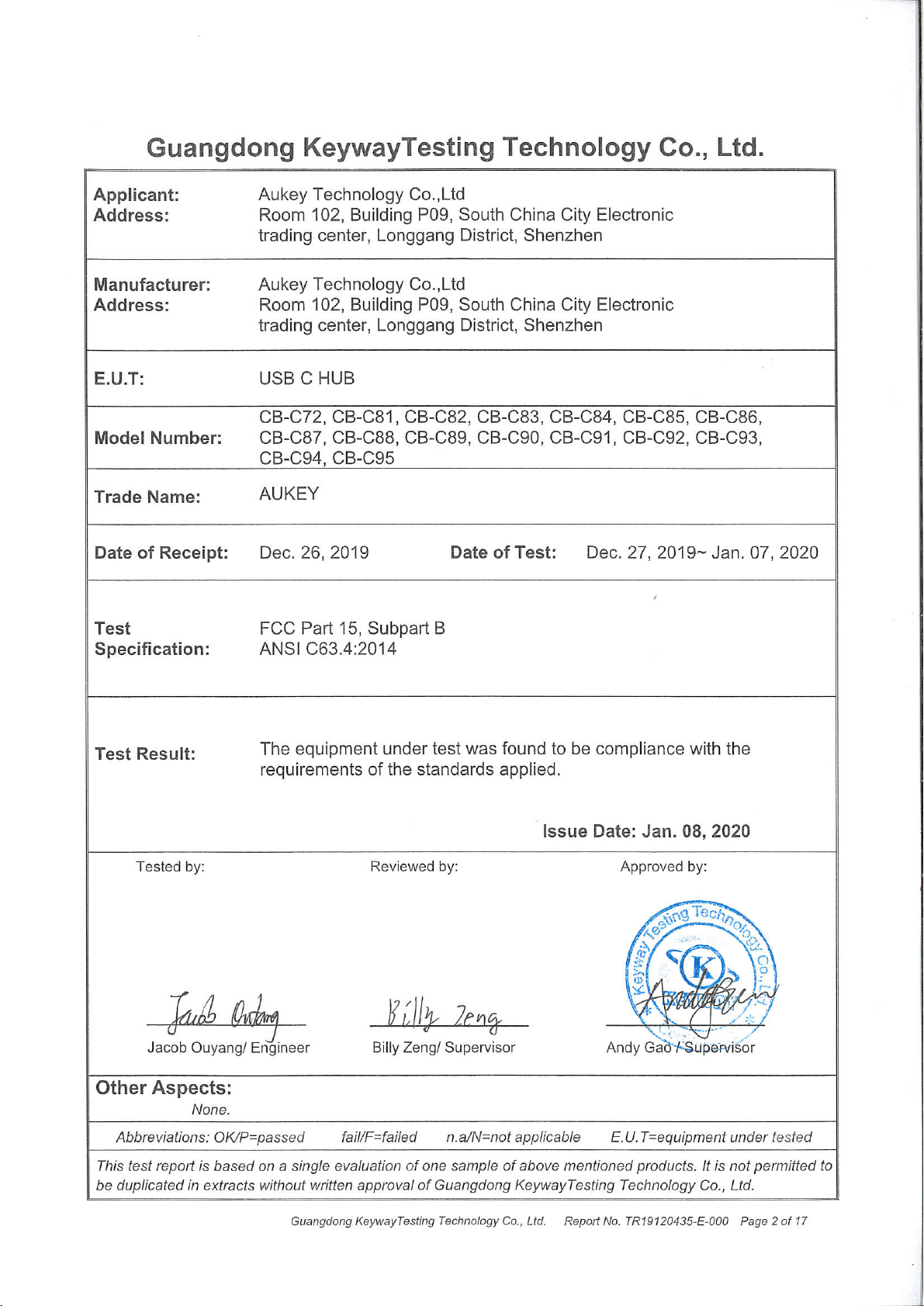

TABLE OF CONTENTS
Test Report Declaration Page
1. GENERAL PRODUCT INFORMATION..........................................................................................4
1.1. Product Function......................................................................................................................... 4
1.2. Description of Device (EUT)......................................................................................................4
1.3. Difference between Model Numbers........................................................................................4
1.4. Independent Operation Modes..................................................................................................4
1.5. Test Supporting System.............................................................................................................4
2. TEST SITES.........................................................................................................................................5
2.1. Test Facilities...............................................................................................................................5
2.2. Test Summary..............................................................................................................................6
2.3. List of Test and Measurement Instruments.............................................................................7
3. TEST SET-UP AND OPERATION MODES...................................................................................8
3.1. Principle of Configuration Selection......................................................................................... 8
3.2. Block Diagram of Test Set-up................................................................................................... 8
3.3. Test Operation Mode and Test Software................................................................................ 8
3.4. Special Accessories and Auxiliary Equipment........................................................................8
3.5. Countermeasures to Achieve EMC Compliance....................................................................8
4. TEST RESULTS..................................................................................................................................9
4.1. Conducted Emission at the Mains Terminals Test................................................................ 9
4.2. Radiated Emission Test (below 1 GHz).................................................................................10
4.3. Radiated Emission Test (above 1 GHz)................................................................................13
5. PHOTOGRAPHS OF TEST SET-UP.............................................................................................14
6. PHOTOGRAPHS OF THE EUT..................................................................................................... 15
Guangdong KeywayTesting Technology Co., Ltd. Report No. TR19120435-E-000 Page3of
17
1. GENERAL PRODUCT INFORMATION
1.1.Product Function
Refer to Technical Construction Form and User Manual.
1.2.Description of Device (EUT)
Description : USB C HUB
CB-C72, CB-C81, CB-C82, CB-C83, CB-C84, CB-C85, CB-C86,
M/N :
Power Input : DC 5V fromPC
Output : DC 5V
Operation
frequency
Remark: CB-C72 was selected as the test model and its data have been recorded in
this report.
1.3.Difference between Model Numbers
Note:All models are the same except the product name
CB-C87, CB-C88, CB-C89, CB-C90, CB-C91, CB-C92, CB-C93,
CB-C94, CB-C95
: <108MHz
1.4.Independent Operation Modes
The basic operation mode is:
Mode Description
Mode 1 Data transmission
1.5.Test Supporting System
1.5.1 PC
Manufacturer : DELL
Model Number : DCNE1F
Power Cord : Unshielded, Detachable, 1.5m
S/N : 13XHTD2Y
1.5.2 TV
TV
Manufacturer : SONY
Model Number : KDL-26X550
Equip No. : 1020345
Guangdong KeywayTesting Technology Co., Ltd. Report No. TR19120435-E-000 Page4of
17

2. TEST SITES
2.1.Test Facilities
Lab Qualifications : 944 Shielded Room built by ETS-Lindgren, USA
Date of completion: March 28, 2011
966 Chamber built by ETS-Lindgren, USA
Date of completion: March 28, 2011
Certificated by TUV Rheinland, Germany.
Registration No.: UA 50207153
Date of registration: July 13, 2011
Certificated by UL, USA
Registration No.: 100567237
Date of registration: September 5, 2012
Certificated by Intertek
Registration No.: 2016-RTL-L2-199
Date of registration: May 10, 2016
Certificated by VCCI
Member No.3498
Facility:966 Chamber: Registration No.: R-4045
Facility:944 Shielded Room :Registration No.:C-4522
Date of registration: September 10, 2016
Certificated by PHOENIX TESTLAB GmbH
Registration No.: 702860c
Date of registration: May 11, 2016
Certificated by CNAS China
Registration No.: CNAS L5783
Date of registration: August 8, 2012
Name of Firm
:
Guangdong Keyway Testing Technology Co., Ltd.
Site Location : No.7 of Zhangmutou District, Guanzhang Road,
Zhangmutou town, Dongguan Guangdong China.
Guangdong KeywayTesting Technology Co., Ltd. Report No. TR19120435-E-000 Page5of
17
2.2.Test Summary
Test Item Condition Standard Result
Conducted disturbance
at mains terminals
Radiated Emission
(below 1 GHz)
Radiated Emission
(above 1 GHz)
Remark: 1. The symbol “N/A” in above table means Not Applicable.
2. Because the EUT employ battery power for operation and which do not operate from the AC
power lines or contain provisions for operation while connected to the AC power lines, so the test
item of Conducted disturbance at mains terminals is not applicable.
3.When determining the test results, measurement uncertainty of tests has been considered.
Test Items Extended Uncertainty
Uncertainty for Radiated Emission in 3m chamber 3.60dB
Uncertainty for Conducted Emission. 2.60dB
150kHz to 30MHz
30MHz to 1GHz
Above 1GHz
System Measurement Uncertainty
FCC Part 15, Subpart B
ANSI C63.4:2014
FCC Part 15, Subpart B
ANSI C63.4:2014
FCC Part 15, Subpart B
ANSI C63.4:2014
N/A
Pass
N/A
Guangdong KeywayTesting Technology Co., Ltd. Report No. TR19120435-E-000 Page6of
17
 Loading...