


bp-9000e
24pin Dot Matrix Printer
OWNER'S MANUAL
BP-9000E

AUI BP-9000E Owner's Manual
- i -
Declare
About Trademark
Corporation names and product names are the registered trademarks or commodity
names of the corporation.
* EPSON and ESC/PK2 are the registered trademarks of Seiko Epson Corporation.
* IBM and IBM 2391 are the registered trademarks of International Business Machines
Corporation.
* Windows is a registered trademark of Microsoft Corporation.

AUI BP-9000E Owner's Manual
- ii -
Important Safety Instructions
Read all of these instructions carefully and thoroughly and save them for later reference. The
unauthorized operation would lead to malfunction or accident. Manufacturers have no
responsibilities for the problems which are led by misoperations.
1. Follow all warnings and instructions in the manual as well as marked on the product.
2. Do not touch the print head if the printer has just been recently used as the print head may be hot.
3. Do not put your fingers under the left and right tractor covers of the tractor when installing the fanfold
paper.
4. Unplug this product from the power outlet before cleaning. Do not use liquid or aerosol cleaners. Use a
damp cloth for cleaning.
5. Do not use this product near water.
6. Do not place this product on an unstable cart, stand or table. The product may fall, causing serious
damage to you or the product.
7. Slots and openings on the cabinet and the back or bottom are provided for air ventilation. To ensure
reliable operation of the product and to protect it from overheating, do not block or cover these
openings. The openings should never be blocked by placing the product on a bed, sofa, rug or other
similar surface. This product should never be placed near or over a radiator or heater. This product
should not be placed in a built-in installation or kiosk stand unless proper ventilation is provided.
8. This product should never be placed near or over a radiator or heat origin, and should avoid of direct
sunshine.
9. Do not locate this product where the cord would be walked on. When the cord or the plug is mangled,
please stop using and get a new one replaced. Make sure the old one is far away from the printer, so it
can avoid someone who does not know the inside story getting damage.
10. Do not use in locations subject to high humidity or dust levels. Excessive humidity and dust may cause
equipment damage or fire.
11. Never push objects of any kind into this product though cabinet slots as they may touch dangerous
voltage dots or short out parts.
12. Don’t remove the printer’s out-cover and repair the printer. When needed, call or take it to the
professional.
13. To ensure safety, please unplug this product prior to leaving it unused for an extended period. The wall
outlet you plan to connect to should be nearby and unobstructed.
14. This product belongs to the impact printer, it produces obviously noise during printing, so we suggest
placing this printer in a relatively independent area.
15. When using the printer in room where ventilation is not good or printing a large amount of files, it is
suggest that to change the air in time.
16. Unplug this product from the power outlet and leave servicing to qualified service personnel under the
following conditions:
A. When the power cord or plug is damaged or frayed.
B. If liquid has been spilled into the product.
C. If the product has been exposed to rain or water.
D. If the product does not operate normally when the operating instructions are followed.
E. If the product has been dropped or the cabinet has been damaged.
F. If the product exhibits a distinct change in performance, it indicates a need for service.
Note: The contents of this manual are subject to change without notice.
* All parts of the printer can be recycled. When it is abandoned, we can call it back freely. Please
contact us when you abandon it.

AUI BP-9000E Owner's Manual
- iii -
Contents
Declare..........................................................................................................................................................i
Important Safety Instructions....................................................................................................................ii
Chapter 1 Function Characteristic............................................................................................................1
Chapter 2 Pr
eparation ..........................................................................................................
......................2
2.1 Unpacking & Checking........................................................................................................................2
2.2 Remov
ing the Protectiv
e Materials......................................................................................................2
2.3 Main Parts of Printer ...........................................................................................................................2
2.4 Ins
talling the Printer ............................................................................................................................3
2.5 Inst
alling the Paper Rack ....................................................................................................................4
2.6 Installing the Soundproof Cover .......................................................................................................... 4
2.7 Inst
alling the Ribbon cartridge.............................................................................................................5
2.8 Connecting the Computer ...................................................................................................................6
2.8.1 Connecting to the Parallel Interface..............................................................................................6
2.8.2 Connecting to the Serial Interface ................................................................................................6
2.8.3 Connecting to the USB Interface ..................................................................................................7
2.8.4 Connecting to
the Ethernet Interface ............................................................................................7
2.9 Connecting to the Power Cord ............................................................................................................7
2.10 Inst
alling Driver .................................................................................................................................8
2.10.1 Auto-installing way
......................................................................................................................8
2.10.2 Manual installing way..................................................................................................................8
2.1
1 Network Settings .............................................................................................................................10
2.11
.1 Connecting Printer ....................................................................................................................10
2.1
1.2 Setting IP Address .................................................................................................................... 11
2.11.3 Installing Printer Network Driver................................................................................................13
Chapter 3 Control Panel...........................................................................................................................20
3.1 Control Panel ....................................................................................................................................20
3.1.1 Control Panel View
.....................................................................................................................20
3.1.2 Function Keys............................................................................................................
.................20
3.1.3 LCD ............................................................................................................................................21
3.1.4 LED indicator .............................................................................................................................. 22
3.1.5 Paper Select
Lever .......................................................................................................
..............22
3.1.6 Gap Adj
ust Lev
er ........................................................................................................................ 22
3.1.7 Self-test ......................................................................................................................................23
3.1.8 Tear Off.................................................................................................................
......................23
3.1.9 Shortcut Key Function
................................................................................................................23
3.2 How to Use the Functional Setup...................................................................................................... 24
3.2.1 Menu setup functional key..........................................................................................................24
3.2.2 Setting examples
........................................................................................................................25
Chapter 4 Prin
ter Setting .........................................................................................................................27
4.1 Setting up the Manual Mode .............................................................................................................27
4.2 Setting up the Tractor
Mode..............................................................................................................27
4.3 Print position .....................................................................................................................................28
4.4 Gap
Adjust Lever...............................................................................................................................29
Chapter 5 Me
nu Function Description....................................................................................................30
5.1 MULTIPART
......................................................................................................................................30
5.2 PAGE FANFOLD
...............................................................................................................................30
5.3 PAGE SINGLE
..................................................................................................................................30
5.4 FONT SELECT
.................................................................................................................................31
5.5 CHAR PITCH ....................................................................................................................................31
5.6 COMPRESS PRN ............................................................................................................................. 31
5.7 T
OF
FANFOLD..................................................................................................................................32
5.8 TOF S
INGLE.....................................................................................................................................32

AUI BP-9000E Owner's Manual
- iv -
5.9 SELECT SETUP ...............................................................................................................................32
5.10 EMULATION
...................................................................................................................................32
5.11 CODE PAGE
...................................................................................................................................33
5.12 CHR TBL EPSON ........................................................................................................................... 33
5.13 CHR T
BL IBM..................................................................................................................................33
5.14 AGM IBM...................................................................................................................
......................33
5.15 CR SETTING ..................................................................................................................................34
5.16 LF SETTING
...................................................................................................................................34
5.17 FF SETTING ...................................................................................................................................34
5.18 LF PITC
H
........................................................................................................................................34
5.19 ZERO STYLE.................................................................................................................................. 34
5.20 INTL FO
NT
......................................................................................................................................34
5.21 FONT LOCK....................................................................................................................................35
5.22 PITCH LOCK...................................................................................................................................35
5.23 QUALIT
Y LOCK .............................................................................................................................. 35
5.24 P
AGE LOCK
....................................................................................................................................35
5.25 TOP MARGIN
..................................................................................................................................35
5.26 BOTTOM MARGIN..........................................................................................................................36
5.27 LEFT MARGIN
................................................................................................................................36
5.28 RIGHT MARGIN..............................................................................................................................36
5.29 PA
RITY BIT.....................................................................................................................................36
5.30 DA
TA LENGTH................................................................................................................................37
5.31 STOP BIT........................................................................................................................................ 37
5.32 PROTOCOL .................................................................................................................................... 37
5.33 BAUD RATE
....................................................................................................................................37
5.34 PRINT DIR .................................................................................................................
.....................37
5.35 COVER DETECT ............................................................................................................................ 38
5.36 QUIET MODE
.................................................................................................................................38
5.37 TEAR OFF ......................................................................................................................................38
5.38 INVERT DISP
...............................................................................................................
...................38
5.39 THAI MODE
....................................................................................................................................38
5.40 VOWEL COMPENS ........................................................................................................................ 38
5.41 FONT MODE...................................................................................................................................39
5.42 DHCP..............................................................................................................................................39
5.43 IP
ADDRESS...................................................................................................................................39
5.44 SUBNET MASK
...............................................................................................................
...............39
5.45 GATEWAY
.......................................................................................................................................39
5.46 MENU LISTING...............................................................................................................................40
Chapter 6 Troubleshooting......................................................................................................................41
6.1 How to Solve the Problem................................................................................................................. 41
6.2 How to Solve the Error Message.......................................................................................................42
6.3 Maintenance......................................................................................................................................43
6.3.1 Clean the printer
.........................................................................................................................43
6.3.2 Lube ...........................................................................................................................................44
6.3.3 How to remove
the printer cover
.................................................................................................45
6.4 Contact the Technical Service Centre ...............................................................................................46
Chapter 7 Printer Specification
...............................................................................................................47
7.1 General .............................................................................................................................................47
7.2 Interface Specifi
cation
.......................................................................................................................49
7.2.1 Parallel Interface.........................................................................................................................49
7.2.2 USB Interface .............................................................................................................................50
7.2.3 Ethernet
Interface ....................................................................................................................... 50
7.2.4 Serial Interface
...........................................................................................................................50
Chapter 8 Paper Specification
.................................................................................................................53

AUI BP-9000E Owner's Manual
- v -
8.1 Paper Specification and Printable Area.............................................................................................53
8.1.1 The Notice Relates to Paper....................................................................................................... 53
8.1.2 Useable Paper
Types and Guarantee Area ................................................................................ 54
8.1.3 Cut Sheet Paper ......................................................................................................................... 54
8.1.4 Fanfold paper .............................................................................................................................58
8.1.5 Envelope.....................................................................................................................................65
8.1.6 Delivery Note
..............................................................................................................................70
8.1.7 Postcard
.....................................................................................................................................70
8.1.8 Passbook.................................................................................................................................... 70
8.1.9 Label....................................................................................................................
.......................70
8.1.10 Reborn Paper
...........................................................................................................................70
Appendix A
Self-test and Adjustment
.....................................................................................................71
A.1 Self-test Function..............................................................................................................................71
A.1.1 ASCII Test Mode.........................................................................................................................71
A.1.2 Hex
Dump Mode ........................................................................................................................ 71
A.2 Alignmen
t Adjust
Mode .....................................................................................................................71
Appendix B Barcode command...............................................................................................................73

AUI BP-9000E Owner's Manual
- 1 -
Chapter 1 Function Characteristic
z Rolling Paper-feed Mechanism.
z Paper type and paper thickness are selectable: It can print with cut sheet paper and fanfold paper (1~9
plies) of different thicknesses (Max. 0.9mm).
z Paper feeding way is adjustable: Friction feeding way can be chose when printing with cut sheet paper;
Tractor feeding way can be chose when printing with fanfold paper.
z It supports 50%, 75%, 83% and 100% Compress Printing.
z The printer supports EPSON ESC/PK2 and IBM 2391 emulations as standard.
z The printer can be configured with parallel interface, serial interface, USB interface or Ethernet
interface.
z Contain the following standard bar codes: EAN-13, EAN-8, Interleaved 2 of 5, Matrix 2 of 5, Industrial 2
of 5, Code 39, Code 128 B, Code 128 C, NW-7.

AUI BP-9000E Owner's Manual
- 2 -
Chapter 2 Preparation
2.1 Unpacking & Checking
Check each item against the following packing list, if any of these items are missing, please contact
your dealer.
2.2 Removing the Protective Materials
1. Open the packing box, take out the printer, and remove the packing materials.
2. Save all the original packing materials, so that they can be used when transport the printer.
2.3 Main Parts of Printer
Figure 2-1 Packing list
Figure 2-2 Main parts of printer (front view)
Interface cable
Printer
Ribbon cartridge
Paper rack
CD-ROM
(Including owner’s manual and drivers)
Power cord
Soundproof Cover
Reverse control panel
Print head
Ribbon cartridge
Paper rack
Platen
Pinch roller
Paper select lever
Power switch
Gap adjust lever
Paper guider

AUI BP-9000E Owner's Manual
- 3 -
Note: Please take the specific interface as standard.
2.4 Installing the Printer
Before placing the printer in your chosen location, consider the following guidelines:
This printer should be placed on a normal table, printer stand or desk. Be sure that the surface is level,
to avoid an uneven load on the carriage as it operates.
Do not place the printer where belong to the following conditions:
The place is overheating or humidity.
The place is shaking.
Do not install the printer where it may be subjected to unsuitable conditions such as:
Where there is excessive dust.
Where it may be splattered with oil or metallic dust.
Where it may be exposed to direct sunlight.
Where it may be accidentally splashed with water.
Figure 2-3 (1) Main parts of printer (rear view)
Parallel interface
Power supply inlet
Serial interface
USB interface
Ethernet interface
Figure 2-3 (2) Main parts of printer (rear view)
L-angle hinge
Printer cover
Soundproof cover
Paper cutter
Tractor lock lever
Rear cover
Tractor cover
Control panel
Paper rack
Top rear cover
AUI BP-9000E Owner's Manual
- 4 -
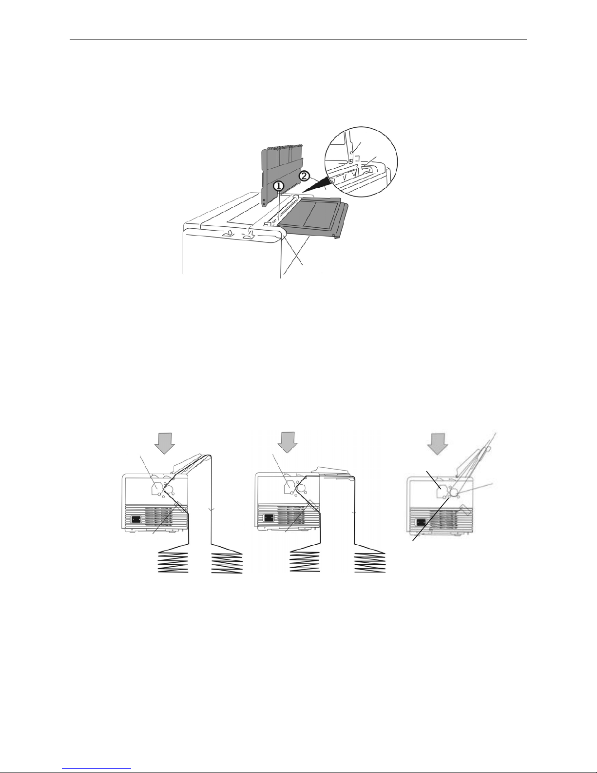
2.5 Installing the Paper Rack
1. Slide the right and left paper guiders to both sides of paper rack.
2. Install the pivots on both sides of paper rack vertically into the groove of top rear cover. (As shown in
Figure 2-4)
Note: When installing or removing paper rack, please move the right and left paper guiders
to the corresponding right and left ends.
3. Put the paper rack vertically when using cut sheet paper; when using fanfold paper, please put it
horizontally. (As Figure 2-5 shown)
Note: As the multi-ply paper is hard, so in order to avoid paper jam during printing, please
put the paper rack slantingly when using such kind of paper.
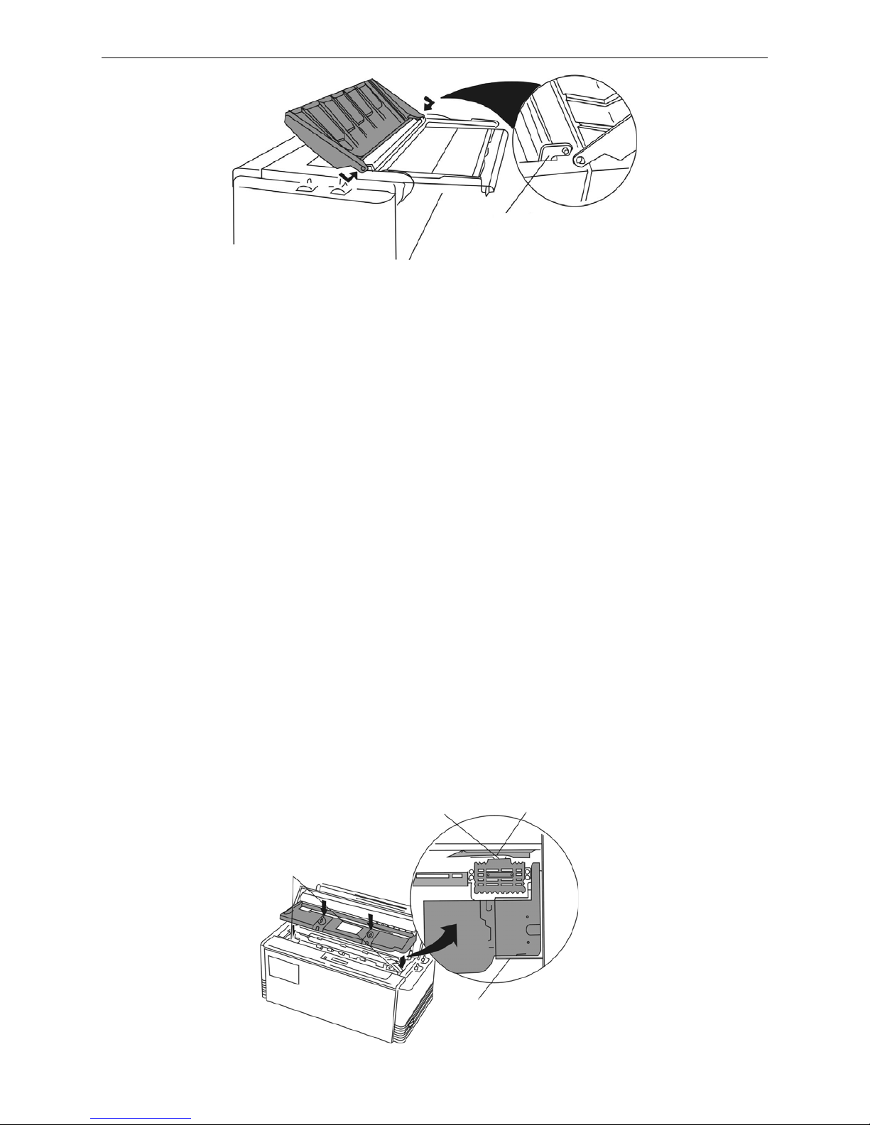
2.6 Installing the Soundproof Cover
1. Reverse soundproof board and place it horizontally on the printer.
2. Plug one hole of soundproof cover into the tab of the L-angle hinge on one side of the printer.
3. Press the L-angle hinge on the other side inwards gently, plug the other soundproof cover hole into
the tab, and then loosen it. (As Figure 2-6 shown)
Top rear cover
Pivots
Groove
Figure 2-4 Installing the Paper rack
Figure 2-5 Placing the paper rack
Tractor
Multiple fanfold paper
Print head
Single ply fanfold paper
Print head
Tracto
r
Frivtion roller
Cut sheet paper
Print head
Platen
AUI BP-9000E Owner's Manual
- 5 -
Note: Make sure the two tabs are plugged into the Soundproof Cover holes entirely, or else,
the Soundproof Cover would get stuck.
2.7 Installing the Ribbon cartridge
1. Make sure the printer is turned off.
Note: Don’t replace the ribbon cartridge when the power is on, or else, it may hurt you when it
suddenly start to work.
2. Open the printer cover.
3. Take out the ribbon cartridge, turn the ribbon feed knob in the direction of the arrow to remove any
slack from the ribbon so it is easier to install. (As Figure 2-7 shown)
4. Place ribbon cartridge into the cartridge holders on the right and left sides, ribbon should be in the
ribbon guide. Check and make sure the ribbon drive shaft on the left side of the cartridge holders
has plugged into the holes on the ribbon cartridge bottom. (As shown in Figure 2-8)
5. Turn the ribbon feed knob in the direction of the arrow to remove any slack from the ribbon.
6. Close the printer cover, pull the gap adjust lever to the proper position to get the best printing result.
L-angle hinge
Cartridge holders
Ribbon guide
Ribbon mask
Cartridge holders
Figure 2-6 Installing the soundproof cover
Figure 2-7 Ribbon cartridge
Figure 2-8 Installing the ribbon cartridge
Ribbon knob
Ribbon core
Ribbon cartridge

AUI BP-9000E Owner's Manual
- 6 -
Caution: Don’t move the print head when the printer is power on, or else, it may damage the printer.
Moreover, don’t touch the print head if the printer has just been recently used as the print
head may be hot.
Note: 1. When your print becomes faint, you need to replace the ribbon cartridge. Otherwise, the
print quality will be affected and the print head may be damage.
2. T o remove the old ribbon cartridge, first make sure the power is turned off, move the print
head to the left of the printer. Then pull out the ribbon from ribbon guide, hold the ribbon
cartridge handle on both sides and lift it out of the printer forwards. Install a new one as
the above steps.
3. Please use the original ribbon cartridge only. Manufacturer will not honor warranty when
using unauthorized ribbon cartridge.
4. Please turn the ribbon knob direction as the arrow shown.
2.8 Connecting the Computer
Your printer can be configured with parallel interface, USB interface, serial interface or Ethernet
interface, (Please take the specific interface as standard.). Connect the printer to your computer as
described below. As Figure2-9, 2-10, 2-11 and 2-12 shown.
Note: Before connecting the parallel interface or the serial interface, please make sure the
power of the printer is shut down. Must after tighten the cable you may turn on the
power, or it will damage the printer.
2.8.1 Connecting to the Parallel Interface
1. Turn off both the computer and the printer. Plug the parallel cable connector securely into the
printer's parallel interface. Squeeze the wire clips together until they lock in place on both sides of
the connector. As shown in Figure 2-9.
2. Plug the other end of the cable into the computer's parallel interface; then tighten the screws on
both sides of the connector, make sure it is tight to the interface.
2.8.2 Connecting to the Serial Interface
1. Turn off both the computer and the printer. Plug the serial cable connector securely into the
printer's serial interface. Then tighten the screws on both sides of the connector. As shown in
Figure 2-10.
2. Plug the other end of the cable into the computer's serial interface; then tighten the screws on both
sides of the connector, and make sure it is tight to the interface.
Figure 2-9 Connect to the parallel interface
Parallel interface
Parallel cable
Wire clips

AUI BP-9000E Owner's Manual
- 7 -
2.8.3 Connecting to the USB Interface
1. Plug the USB cable A end (flat shape) into the computer's USB interface.
2. Plug the USB cable B end (square shape) into the printer's USB interface. (As Figure 2-11 shown)
Note: Don't impact the plug after connecting the USB cable.
2.8.4 Connecting to the Ethernet Interface
Plug the RJ-45 crystal plug of the Ethernet cable into the printer, and plug the other plug into the LAN.
As shown in Figure 2-12.
Note: The details of the network setting please refer to the relative contents in this. owner’s
manual.
2.9 Connecting to the Power Cord
1. As shown in Figure 2-13. Make sure the printer is turned off. (The pressed down side of the power
switch with “O” marks denotes the printer is off.)
Figure 2-11 Connect to the USB interface
Figure 2-12 Connect to Ethernet interface
Figure 2-10 Connect to the serial interface
Serial cable
Serial interface
Screw
USB cable
USB interface
Ethernet interface
Ethernet cable

AUI BP-9000E Owner's Manual
- 8 -
2. Make sure the voltage required by the printer matches that of your electrical outlet.
3. Plug one end of the power cord into the printer’s power supply inlet.
4. Plug the other end of the power cord into an electrical outlet which connecting the ground
properly.
To turn the printer ON, press the I mark at the side of the power switch.
To turn the printer OFF, press the O mark at the side of the power switch.
Caution: 1. If the rated voltage doesn’t match the outlet voltage, don’t plug in the power cord,
and then contact your dealer for assistance.
2. Use the electrical outlet which connecting the ground properly.
Note: After turn off the printer, you should wait more than 3 seconds before you restart the printer.
Or it may lead to initialization error.
2.10 Installing Driver
Please use the cable to connect computer with printer, then turn on the computer and the printer, put
the driver CD into the CD-ROM. Install driver by the following way:
2.10.1 Auto-installing way
Double click the file “Setup.exe” in the driver disc, install driver by the following direction.
Note: The auto-installing way just runs in the operation system of Windows 2000 or above.
2.10.2 Manual installing way
Note: The hand-operated installing ways of serial interface and parallel interface are the
same.
1) The installing steps of parallel interface for Windows 2000/XP/Vista are as follows:
1 Click “Start” → “Settings” → “Printer and Faxes”.
2. Click “Add Printer”, then it pops up a printer cover of “Add Printer Wizard”, click “Next”, then
please read the select guide carefully, such as, select “Local printer” in the “Local or Network
Printer” printer cover, then click “next”.
3. A printer cover of “Select a Printer Port” pops up, select a usable port. Such as, select “LPT1:
(Recommended Printer Port)”, (if you need to install to other ports, please select the respective
port), click “Next”.
4. A printer cover of “Install Printer Software" pops up, click “Have Disk...”, click “Next”.
5. A printer cover of “Install From Disk” pops up. Please according to the operating system
environment, you should select the path as follow: CD-ROM → “Driver” → “WIN2000
Figure 2-13 Connect the power cord to the printer
Grounding
Power supply inlet
Power cord
Electrical outlet

AUI BP-9000E Owner's Manual
- 9 -
(XP-Vista-Win7)”, click “Open”, then click “OK” to return to the printer cover of “Install Printer
Software”, click “Next”.
6. Follow the guide click “Next” gradually till the installation is finished.
2) The installing steps of parallel interface for Windows 7 are as follows:
1. Click “Start” → “Device and Printers”.
2. Click “Add Printer”, then it pops up a printer cover of “Add Printer Wizard”, click “Next”, then
please read the select guide carefully, such as, select “Local printer” in the “Local or Network
Printer” printer cover, then click “next”.
3. A printer cover of “Select a Printer Port” pops up, select a usable port. Such as, select “LPT1:
(Recommended Printer Port)” (if you need to install to other ports, please select the respective
port), click “Next”.
4. A printer cover of “Install Printer Software” pops up, click “Have Disk...”, click “Next”.
5. A printer cover of “Install From Disk” pops up. Please according to the operating system
environment, such as Windows XP operating system, you should select the path as follow:
CD-ROM → “Driver” →“WIN2000 (XP-Vista-Win7)”, click “Open”, then click “OK” to return to the
printer cover of “Install Printer Software”, click “Next”.
6. Follow the guide click “Next” gradually till the installation is finished.
The USB interface installing steps for Windows 2000/XP/Vista/Win7 are as follows:
The following steps are used Windows XP as example. There are slight differences among different
operating systems.
1. Connect the printer to computer with an USB cable and turn on the printer.
2. After the computer find out new hardware and finish searching, pop up a printer cover of “Found
New Hardware Wizard”, choose “Install from a list or specific location (Advanced)”, click “Next”.
3. A printer cover of “Found New Hardware Wizard” — “Please choose your search and installation
options” pops up, choose “Don't search, I will choose the driver to install”, click “Next”.
4. A printer cover of “Add Printer Wizard” pops up, click “Have Disk...”, click “Browse”.
5. A printer cover of “Install From Disk” pops up. Please according to the operating system
environment, you should select the path as follow: CD-ROM → “Driver” → “WIN2000
(XP-Vista-Win7)”, click “Open”, then click “OK” to return to the printer cover of “Add Printer Wizard",
click “Next”.
6. Follow the guide click “Next” gradually till the installation is finished.
The installing steps for Windows 98 are as follows:
(1) The installing steps with a parallel cable or a serial cable:
1. Click “Start” → “Settings” → “Printers”.
2. Click “Add Printer”, then a printer cover of “Add Printer Wizard” pops up, click “Next”, then please
read the select guide carefully, such as, select “Local printer” in the “Local or Network Printer”
printer cover, then click “Next”.
3. A printer cover of “Click the manufacturer and model of your printer” pops up, click “Have Disk...”,
please click “Browse”, select the path as follow: CD-ROM → “Driver” → “WIN98 (WINME)”, then
click “OK”.
4. A printer cover of “Install From Disk” pops up, click "OK, return to a printer cover of “Add Printer”,
select the respective model, and then click "Next".
5. A printer cover of “Printer port” pops up, select “Available ports”, such as, select “LPT1: Printer
Port”, click “Next”, and then show the printer’s name. If the system is not installed by other printer
driver process, the printer is treated as
default printer by the application process of printer
cover 98

AUI BP-9000E Owner's Manual
- 10 -
environment, click “Next”. Otherwise, according to prompt, choose the printer is default: “Yes”,
click “Next”, choose “Yes-(recommended)”, click “Finish”. A printer cover of “Printer test page
completed” pops up, click “Yes”.
6. The printer driver process is installed successfully.
(2) The installing steps with an USB cable:
Note: 1. As the system of Windows 98/ME doesn’t have integrated USB driver control, please
install USB driver before using USB interface printing. Then install USB printer driver.
2. If it has installed the USB driver, please install the USB printer driver directly as the
following steps.
USB driver installing steps:
1. Connect an USB cable and turn on the printer.
2. After the computer find out new hardware and finish searching, a printer cover of “Add New
Hardware Wizard” pops up, click “Next”.
3. A printer cover of “Add New Hardware Wizard” — “Windows operation” pops up, choose “Search
the best driver for the device (recommended)”, and click “Next”.
4. A printer cover of “Search for new drivers” pops up, check “Specify a location”, click “Browse”,
select the path as follows: CD → ROM → “Driver”-“[WIN98 (WINME) \ USBdriver]”, then click
“OK”.
5. Return to a printer cover of “Search for new drivers”, click “Next”; a printer cover of “Windows
driver file search for the device” pops up, click “Next”.
6. After the system finishing installing the file automatically, a window of “USB Print Supported”
pops up, click "Finish".
7. The printer USB driver process is installed successfully.
USB printer driver installing steps:
1. Click “Start” → “Settings” → “Printers”.
2. Click “Add Printer”, then a printer cover of “Add Printer Wizard” pops up, click “Next”.
3. A printer cover of “Click the manufacturer and model of your printer” pops up, click “Have Disk...”,
please click “Browse”, select the path as follow: CD-ROM → “Driver” → “WIN98 (WINME)”, and
then click “OK”.
4. A printer cover of “Install From Disk” pops up, click “OK”, return to a printer cover of “Add Printer”,
then click "Next".
5. A printer cover of “Printer port” pops up, select “Available ports”, select “JMUSB”, click "Next",
and then show the printer’s name. If the system is not installed by other printer driver process,
the printer is treated as default printer by the application process of printer cover 98 environment,
click “Next”. Otherwise according to prompt, choose the printer is default: "Yes", click "Next"
choose “Yes-(recommended)”, click “Finish”. A printer cover of “Printer test page completed”
pops up, click “Yes”.
6. The printer driver process is installed successfully.
2.11 Network Settings
Caution: The network printing function needs the operation system of Windows 2000 or above.
2.11.1 Connecting Printer
Power on the printer, connect with the Ethernet cable which has been connected to LAN, and look into
the information of Ethernet LED indicator to ensure the printer has entered into the normal connection.
AUI BP-9000E Owner's Manual
- 11 -
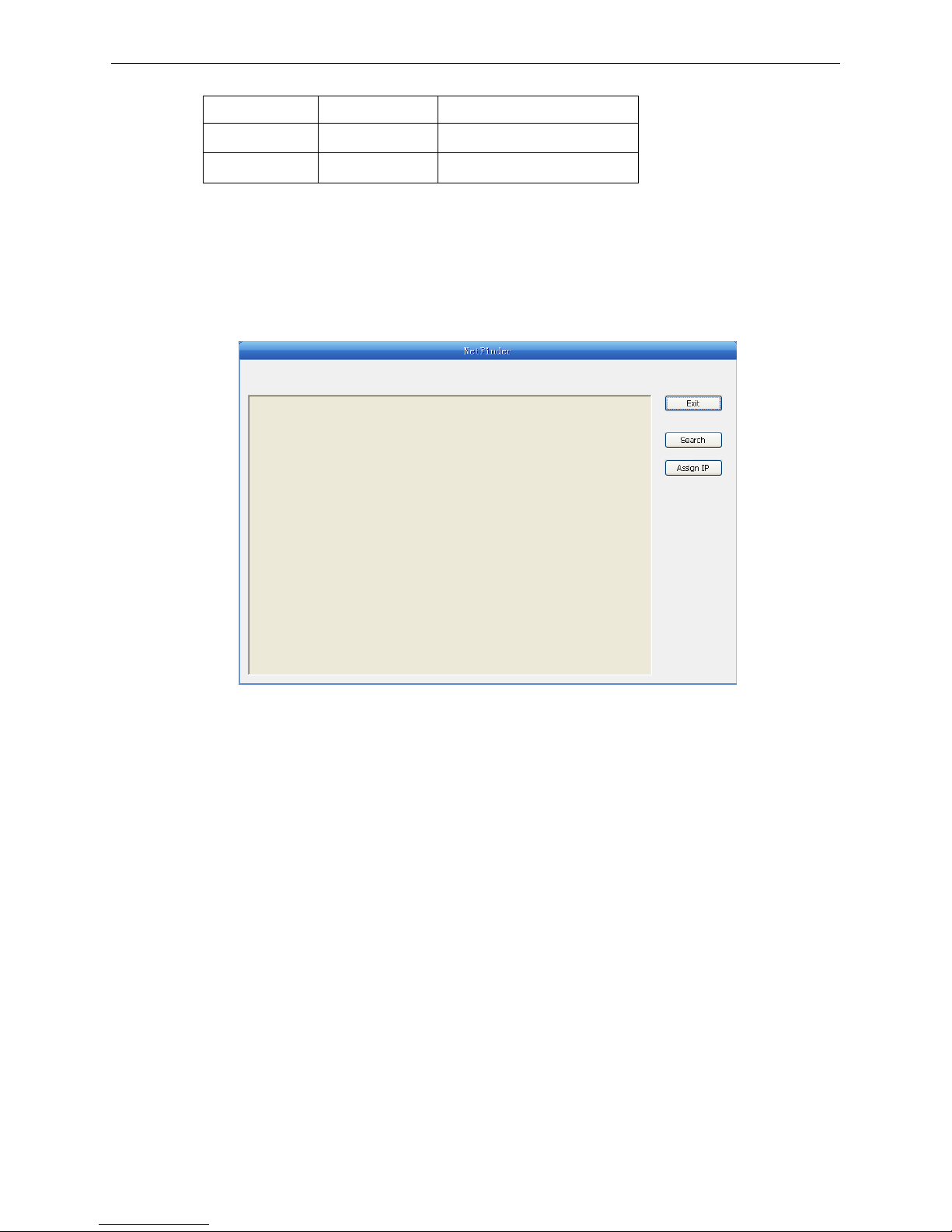
2.11.2 Setting IP Address
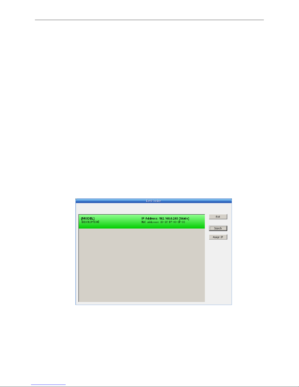
1. Run NetFinder Software
Double click NetFinder.exe in the PC, which connects the printer in the same LAN. The figure of
the software is shown as follows:
2. Search printer
Click “Search” button in the main interface, the dialog box appearing will begin searching
automatically and show appearance, listing a printer in the main interface if found. The time is
counting down in the progress bar (10s in total) and the search will finish as soon as the time is
over. When going on searching, press “search” button again.
Yello w LED Green LED Description
ON BLINK Connect to network
OFF OFF Not connect to network
Button description:
Exit — Exit from the software
Search — Search printers in the same LAN
Assign IP — Modify the IP address and other settings for the specified printer.
AUI BP-9000E Owner's Manual
- 12 -
If the printer still can not be found out when the network connection is correct and in the same
network, Please check whether the network fire wall on the PC open or not. If there is a fire wall,
please close it temporarily, open it again after finishing searching and setting a printer completely.
3. Setting printer’s IP address
The printer’s information is listed in the main interface, the left side of which is the model and
description and the right is the IP and MAC address. What’s more, the assign mode
(dynamic/static) is noted behind the IP address.
1) Correlative description for IP address settings
In order to search and set printer’s IP address conveniently for the first time, the factory default
setting is DHCP mode which assigns IP address dynamically. If there is no DHCP server in the
connected LAN and printer is set to DHCP mode as well, then it will use the internal pre-set
address (IP: 10.0.0.1, Subnet Mask: 255.255.255.0) automatically.
It is suggested that printer’s IP set to static in actual usage, which can cut down the time when
initializing the Ethernet interface as the printer is turned on and prevent IP conflicts (The dynamic
address used in printer may conflict with another one). The network segment part of the IP
AUI BP-9000E Owner's Manual
- 13 -
address and Subnet Mask must be the same as those of PC connecting with a printer. For
example, the address of working PC is 192.168.0.1/255.255.255.0 (IP/Subnet Mask), then which
of printer should be set to 192.168.0.x/255.255.255.0(x=2~254 and should avoid the IP in used. It
is not restricted for NetFinder to search printers in the same network but different segment parts
(can not stride gateway). Relative glossary of IP address may refer to corresponding information.
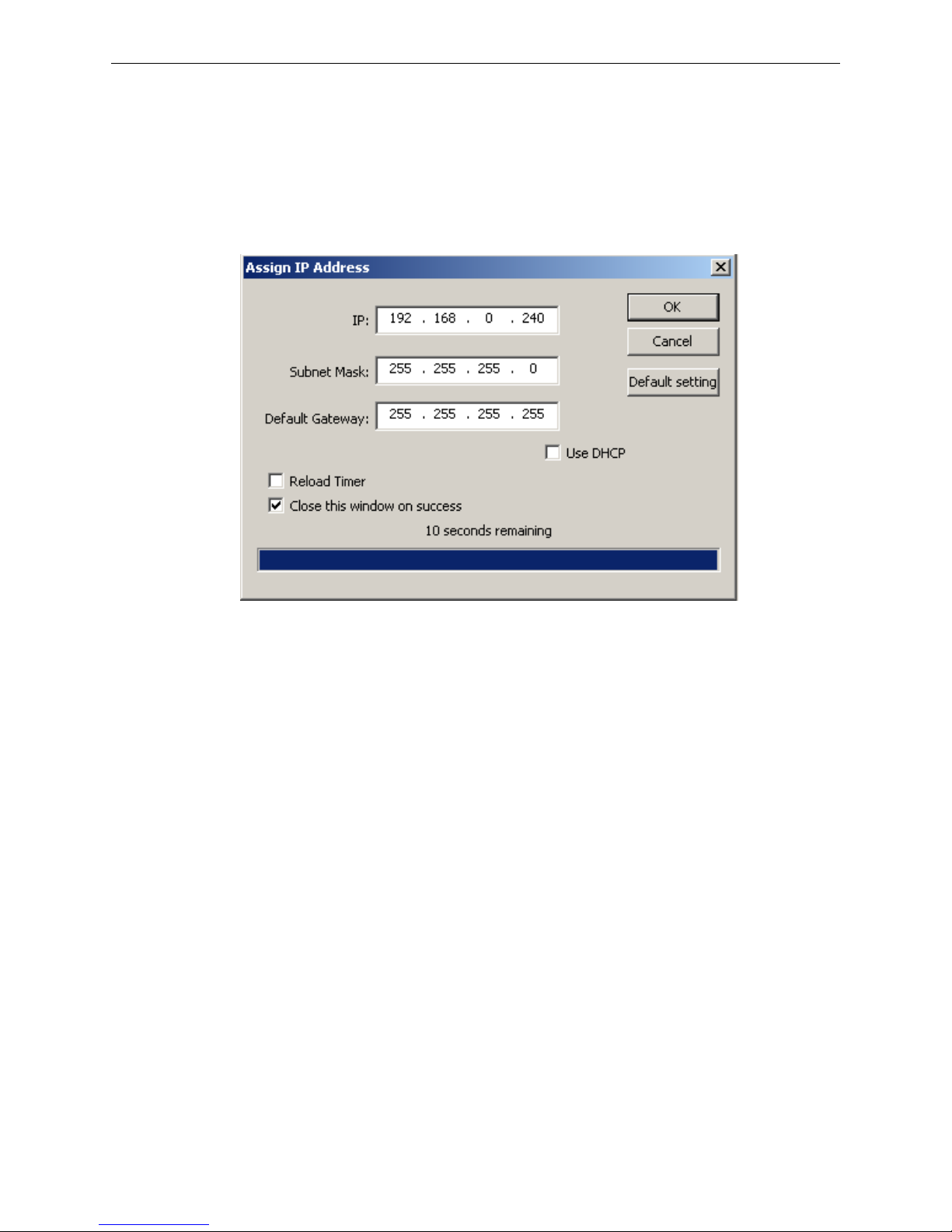
2) Setting printer’s IP address
Select the printer information to be modified (black frame appears), click “Assign IP” button. Set
the IP in the dialog box appearing.
Check the “Use DHCP” if need to assign dynamic address, the settings above will be disabled
automatically. Please make sure there is a DHCP server in the network, or the printer can not
receive an effective IP address.
When to specify static address, uncheck “Use DHCP” and fill in “IP address”, “Subnet Mask” and
“Default Gateway”. If there is no gateway in the network, fill 255.255.255.255 in the “Default
gateway”. “IP address” and “Subnet Mask” should obey the assigning rules of local LAN (Ethernet),
please enquire the administrator of networks which the printer connects to for more details.
Click “OK” to send address setting information to the specified printer. The printer takes response
after “Close this printer cover on success” is checked, and then this dialog is closed automatically.
Select “Reload Timer” then the software will wait for the printer’s response. Generally, printer will
take response in a circle time if network connection is correct.
Click “Cancel” if you abandon the modification.
Click “Search” in the main interface again to update printer information after modifying the printer’s
IP address.
3) Report printer’s IP address
Report the printer’s IP address, which will be used in the section “Newly-install printer network
driver” or “Upgrade-install printer network driver (setting driver’s network port)”.
2.11.3 Installing Printer Network Driver
The ways of installing network driver are divided into Newly-install way and Upgrade-install way
according to whether the PC installs the printer driver or not.
If the printer driver hasn’t been installed on the PC, adopt newly-install way whose steps are shown in
“Newly-install printer network driver”.
If the printer driver has been installed on the PC, adopt Upgrade-install way whose steps are shown in
“Upgrade-install printer network driver”.
AUI BP-9000E Owner's Manual
- 14 -
1. Newly-install printer network driver
1) Click “Start” → “Settings”, select “Printers”.
2) Click “Add printer”, then a printer cover of “Add Printer Wizard” pops up, click “next”, then please
read the select guide carefully. Such as, select “Local or Network Printer”, then click “next”.
3) A printer cover of “Select the Printer port” pops up, select a port you want your printer to use. For
example, select “Create a new port”, select “Standard TCP/IP Port” in the port, click “next”.
4) A printer cover of “Add standard TCP/IP Printer Port Wizard”, click “Next”.
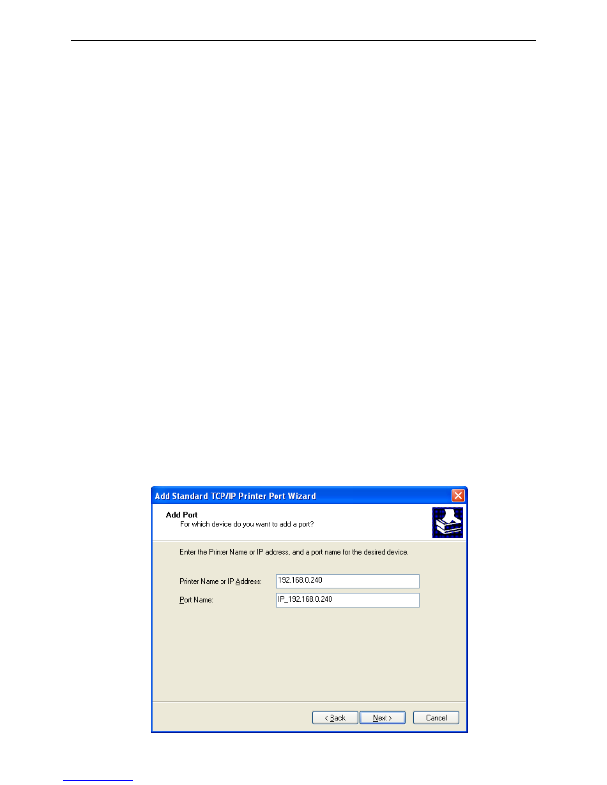
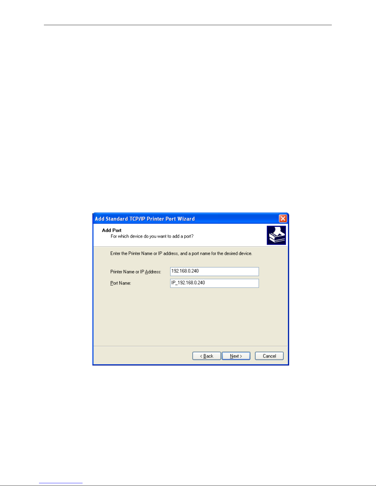
5) A printer cover of “Add Port” pops up, enter the IP address reported by the “Setting printer’s IP
address” in the “Printer Name or IP Address” column. Take IP address “192.168.0.240” for
example. “Port Name” is created automatically after finishing filling in IP address.
AUI BP-9000E Owner's Manual
- 15 -
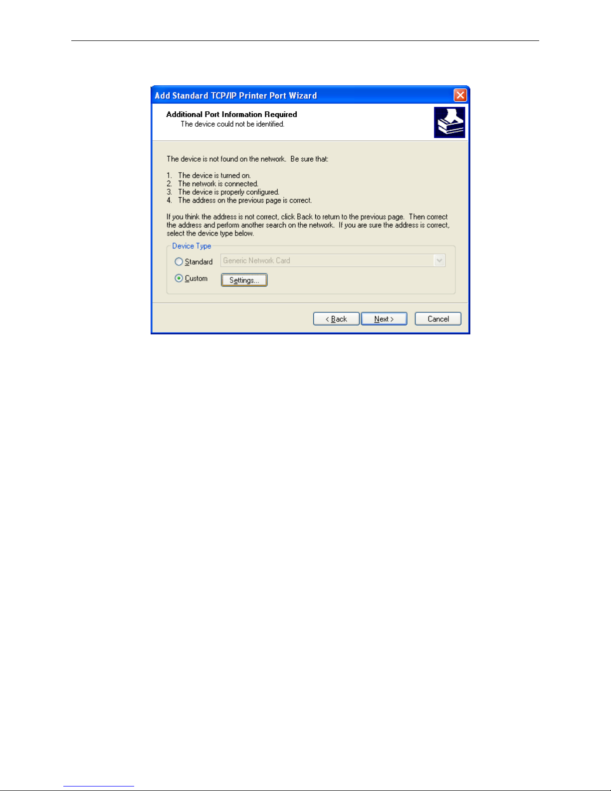
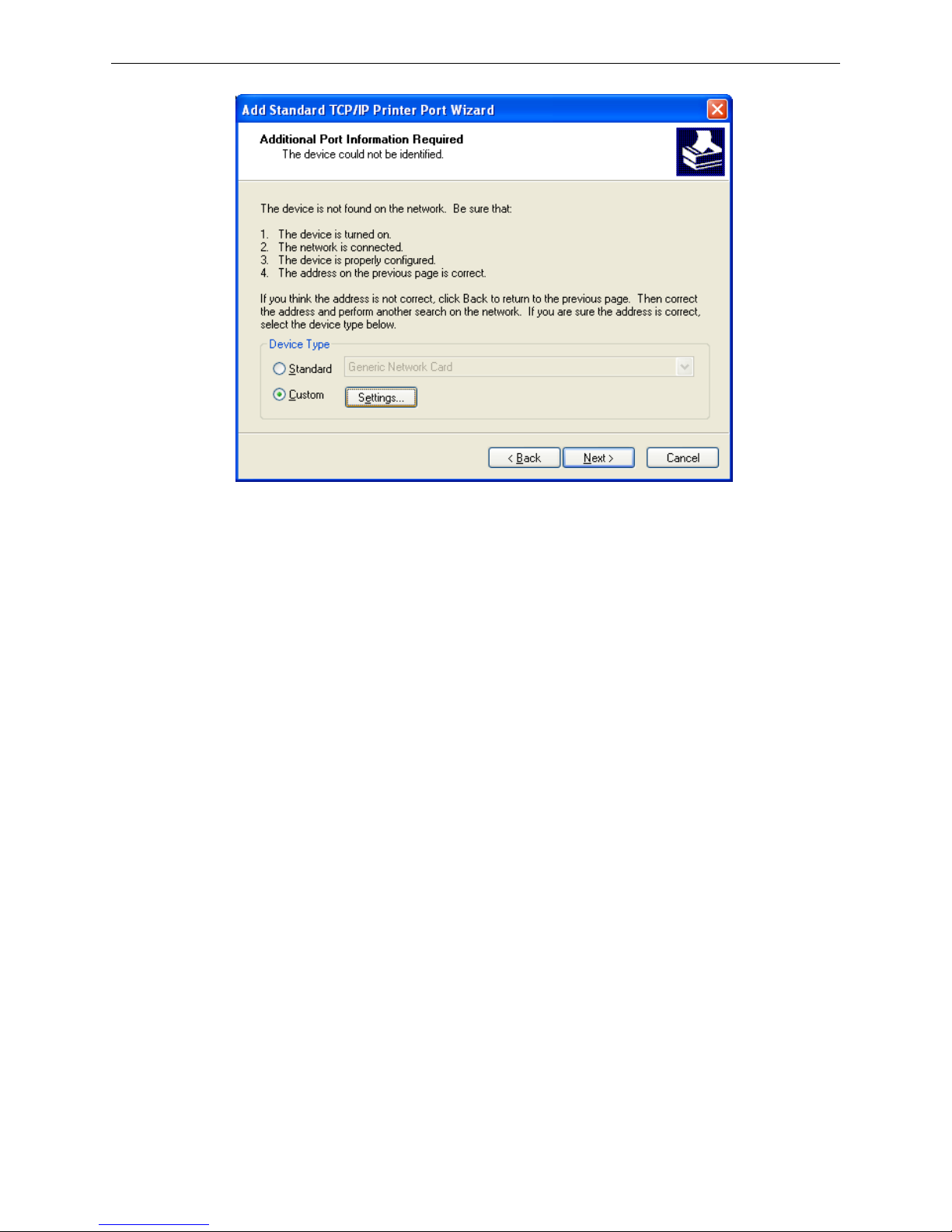
6) A printer cover of “Additional Port Information Required” pops up, select “Custom” in the “Device
Type”, then click “Settings”.
7) A printer cover of “Port Settings” pops up. Affirm that “Port name” and “Printer name or IP
address” are correct, “Protocol” is “RAW” and “Port Number” is “9100”, click “OK”.

AUI BP-9000E Owner's Manual
- 16 -
8) Return to “Additional Port Information Required”, click “Next”.
9) A printer cover of “Completing the Add Standard TCP/IP Printer Port Wizard” pops up, click “Finish”.
10) In the selection of “Manufacturers/Printers”, click “Have Disk”, and then click “Next”.
11) A printer cover of “Install From Disk” pops up. Please according to the operating system
environment, such as Windows 2000/XP/Vista/Win7 operating system you should select the path
as follows: CD-ROM → “Driver” → “WIN2000 (XP-Vista-Win7)”, click “open”, then click “OK”, then
return to the window “install printer software”, click “next”.
12) Follow the direct click “next” gradually till the installation is finish. At this time, printer network driver
is installed completely.
2. Upgrade-install printer network driver (setting driver’s network port)
If PC has installed the printer’s driver, set driver’s network port to carry out network printing. The
concrete steps are shown below:
1) Click “Start” → “Settings”, select “Printers”.
2) Right click this printer driver, click “Properties” on the printer cover coming out.
3) A printer cover of “Properties” pops up, click “Ports” and “Add Ports”.
4) A printer cover of “Printer port” pops up, select “Standard TCP/IP Port”, click “New port”.
AUI BP-9000E Owner's Manual
- 17 -
5) A printer cover of “Add Standard TCP/IP Printer Port Wizard” pops up, click “Next”.
6) A printer cover of “Add a port” pops up, import the IP address reported by the “Setting printer’s IP
address” in the “Printer name or IP address” column. Take IP address “192.168.0.240” for example.
“Port name” is created automatically after finishing filling in IP address. Click “Next”.
7) A printer cover of “Additional Port Information Required” pops up, select “Custom” in the “Device
Type”, then click “settings”.
AUI BP-9000E Owner's Manual
- 18 -
8) A printer cover of “Port Settings” pops up. Affirm that “Port name” and “Printer name or IP address”
are correct, “Protocol” is “RAW” and “Port Number” is “9100”, click “OK”.
 Loading...