

Page 1

Owner’s manual
Power amplification integrated system for cars
2000
EDITION
62018 Potenza Picena (MC) Italy • Tel. ++39.0733.870870 • Fax ++39.0733.870880 • http://www.audison.com • e-mail: com@audison.com
is a division of
Page 2
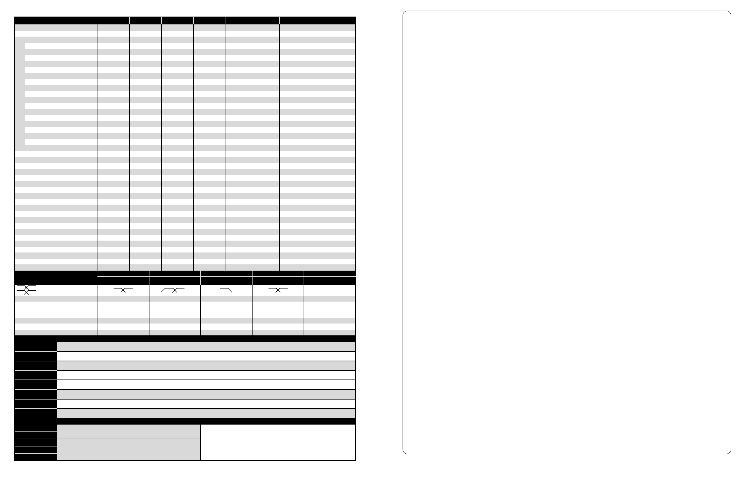
AUDISON’S MEASUREMENT STANDARDS
Power measures taken according to audison standard 1998 edition.
- 12 VDC and 13.8 VDC.
- 1 kHz or crossover cut-off frequency.
- 0.3 % THD nominal power; 1% THD continuous power.
- Tolerance: +10 %; -5 %.
- Continuous power given by RMS Voltage measured on resistive load.
- The nominal power of the amplifier is measured upon a battery voltage of 12 Volts with a 4 Ohm load
and with all channels in function.
- 69 -
12 12 24 HI-PASS 12/LO-PASS 24
✓✓✓✓
HI-PASS; LO-PASS; BYPASS HI-PASS; BYPASS LO-PASS; BYPASS HI-PASS; LO-PASS; BYPASS BYPASS
CROSSOVER SLOPE
CONTINUOUS ADJUSTMENTS
PRE-OUT FUNCTION
TERMINALS FOR PROTECTING CONNECTIONS; IT IS POSSIBLE TO INVERT THEIR FRONT
PANEL IN ORDER TO FIX THEM WITH HIDDEN SCREWS.
RACCORDS BETWEEN TWO AMPLIFIERS FOR PROTECTING CONNECTIONS; PROVIDED
WITH A 24K GOLD PLATED BRASS PLATE WHICH CAN BE PERSONALISED.
ANALOGUE PHASE CONTROL. CONTINUOUSLY ADJUSTABLE PHASE BETWEEN 0˚ AND 360˚, SELECTION ON THREE FREQUENCY RANGES (40-200 HZ; 200-800 HZ; 8004500 HZ). BY-PASS SWITCH.
ONE BAND PARAMETRIC EQUALISER WITH CONTINUOUS CONTROLS FOR: FREQUENCY (SELECTABLE IN THREE STEPS, FROM 20HZ TO 20KHZ), GAIN (-9DB, +9DB), BAND
WIDTH (Q FROM 1 TO 4). BY-PASS SWITCH.
ADDITIONAL MODULE FOR CONTROLLING SEVERAL CHANNELS. IF IT IS MOUNTED IN A FURTHER BTX2, IT CONTROLS ALSO REAR CHANNEL WITH ONLY ONE VCRDK.
GRADUAL INTERVENTION COOLING SYSTEM CONTROLLED BY THE AMPLIFIER TEMPERATURE. MIN. STARTING THRESHOLD TEMPERATURE: 44˚C; MAX. EFFICIENCY TEMPERATURE:
74˚C. IT CONSISTS OF TFC CONTROLLER MODULE TO MOUNT INSIDE THE AMPLIFIER AND TWO FANS GROUPS, TO PLACE INTO A TERMINAL OR A RACCORD.
TRM4
TRM6
RC08
RC10
RC12
MULTICHANNEL
EXTENSIONS
HI/LO-PASS BAND/HI-PASS LO-PASS MONO
BALANCED PRE OUT
HL12 BH12
LM24
HL24 BSA1
PRM3
SM24
PC36
DSC1
VCRDK
VCA1D
BTX2
MAC2
CONTROL EXTENSIONS
AMPLIFIERS
VRx 1.500
VRx 2.150 VRx 2.250 VRx 2.400 VRx 4.300 VRx 6.420
POWER @ 13,8V
HOUSING DUCTS FOR MAC2 FANS.
24DB/OCT. MONO SUBSONIC FILTER. CONTINUOUSLY ADJUSTABLE FREQUENCY BETWEEN 14 AND 36HZ. BY-PASS SWITCH.
DEPENDENT ADJUSTMENTS
INDEPENDENT ADJUSTMENTS
AMP-OUT/PRE-OUT SWITCHING
✓✓✓✓
CUT OFF FREQUENCIES 40-5k
BAND-PASS LO 40-2k
BAND-PASS HI 150-5k
HI-PASS 150-5k
40-90
LO-PASS 40-90
HI-PASS 40-120
500x1
75x4+85x2
560x1
1080x1
2000x1
0.02
100
8-4-2-1
✓
75x2
110x2
180x2
240x2
360x1
480x1
0.02
100
✓
8-4-2-1
8-4-2
✓
125x2
160x2
280x2
420x2
560x1
840x1
0.02
100
✓
8-4-2-1
8-4-2
✓
200x2
250x2
450x2
580x2
900x1
1160x1
0.02
100
✓
8-4-2-1
8-4-2
✓
65x4+80x2
120x4+150x2
75x4 (4Ω)+165x2 (2Ω)
75x4 (4Ω)+250x2 (1Ω)
75x4+330x1
75x4 (4Ω)+500x1 (2Ω)
110x4+430x1
0.02
100
✓
Ch.A & Ch.B: 8-4-2; Ch.C: 8-4-2-1
Ch.A & Ch.B: 8-4; Ch.C: 8-4-2
✓✓✓
75x4
110x4
175x4
220x4
102x2+380x1
90x2 (4Ω)+530x1 (2Ω)
350x2
440x2
0.02
100
✓
Ch.A & Ch.B: 8-4-2-1
Ch.A & Ch.B: 8-4-2
✓✓
Nominal Power @ 12V
6 ch. mode - 4Ω
1222 4 6
Number of channels
Distortion - THD (1 KHz)
A weighed S/N ratio
0.15-1.5/0.5-5 0.15-1.5/0.5-5 0.15-1.5/0.5-5 0.15-1.5/0.5-5 0.15-1.5/0.5-50.15-1.5/0.5-5
Hi-Lo input sensitivity
Use in bridge
✓✓✓ ✓✓
Use in tri-mode
Stereo load impedance
Mono/bridge load impedance
PRM3 option
✓✓✓✓ ✓✓
SM24 option
✓✓✓✓ ✓✓
PC36 option
✓
DSC1 option
✓✓✓✓ ✓✓
BTX2 option
✓✓✓✓ ✓✓
VCRDK option
✓✓✓✓
HL12 option
✓✓✓
BH12 option
✓✓✓✓
LM24 option
✓✓✓✓
HL24 option
✓✓✓✓
BSA1 option
✓✓✓✓ ✓✓
MAC2 option - with TRM or RC
✓✓✓✓ ✓✓
RC08 - RC10 - RC12 option
NP - Nominal Power (+10%, -5%) @ 4Ω - 12V - 0,3% THD.
AUTOMATIC DYNAMIC PROCESSOR FOR SUBWOOFER RESPONSE CONTROL.
SYSTEM FOR MASTER VOLUME REMOTE CONTROL IF USED IN BTX2 OR FOR LEVEL CONTROL OF ANY WAYS IN A MULTIAMPLIFIED SYSTEM IF USED IN VRX. BASED ON
VCA1D WITH DIGITAL CONTROL.
ABS BALANCED LINE TRANSMITTER. THREE STEP GAIN CONTROL (0DB, +3DB, +6DB) AND PEAK LED. OPTIONAL VCA MODULE FOR LEVEL CONTROL. YOU CAN REALISE
MASTER VOLUME IN FRONT/REAR SYSTEMS USING TWO BTX2, ONE VCRDK AND ONE VCA1D.
Ω
Ω
dBA
VRMS
*
*
6 ch. mode - 2Ω
6 ch. mode - 4/2Ω
6 ch. mode - 4/1Ω
5 ch. mode - 4Ω
5 ch. mode - 4/2Ω
5 ch. mode - 2Ω
4 ch. mode - 4Ω
4 ch. mode - 2Ω
4 ch. mode - 1Ω
3 ch. mode - 4Ω
3 ch. mode - 4/2Ω
2 ch. mode - 4Ω
2 ch. mode - 2Ω
2 ch. mode - 1Ω
1 ch. mode - 4Ω
1 ch. mode - 2Ω
1 ch. mode - 1Ω
W
W
W
W
W
W
W
W
W
W
W
W
W
W
W
W
W
W
W
%
dB/oct.
Hz
HI-PASS STEREO
LO-PASS MONO
COOLING DUCT EXTENSIONS
✓✓✓✓ ✓✓
TRM4 - TRM6 option
Page 3
- 1 -
- Objectives of VRx project . . . . . . . . . . . . . . . . . . . . . . . . . . . . . . . . . . . . . . . . . . . p. 2
- General features . . . . . . . . . . . . . . . . . . . . . . . . . . . . . . . . . . . . . . . . . . . . . . . . . . p. 3
- VRx - MODULAR EXTENSIONS: CONTROL EXTENSIONS
- PRM3 stereo parametric equaliser . . . . . . . . . . . . . . . . . . . . . . . . . . . . . . . . . . . . . . p. 6
- SM24 24 dB/oct. mono subsonic filter . . . . . . . . . . . . . . . . . . . . . . . . . . . . . . . . . . . p. 6
- PC36 360° phase controller . . . . . . . . . . . . . . . . . . . . . . . . . . . . . . . . . . . . . . . . . . p. 7
- DSC1 sub dynamic control . . . . . . . . . . . . . . . . . . . . . . . . . . . . . . . . . . . . . . . . . . . p. 8
- VCRDK digital remote volume control kit (VCRD + VCA1D) . . . . . . . . . . . . . . . . . . . . p. 8
- MAC2 forced air modulated cooling system . . . . . . . . . . . . . . . . . . . . . . . . . . . . . . . p. 9
- Insertion of fans group into Terminals and Raccords . . . . . . . . . . . . . . . . . . . . . . . . . p. 10
- BTX2 stereo balancer/preamplifier . . . . . . . . . . . . . . . . . . . . . . . . . . . . . . . . . . . . . p. 11
- VRx - MODULAR EXTENSIONS: MULTICHANNEL EXTENSIONS
- HL12 12 dB/oct. HI/LO-PASS crossover . . . . . . . . . . . . . . . . . . . . . . . . . . . . . . . . . . p. 14
- BH12 12 dB/oct. BAND/HI-PASS crossover. . . . . . . . . . . . . . . . . . . . . . . . . . . . . . . . p. 15
- LM24 24 dB/oct. LO-PASS mono crossover . . . . . . . . . . . . . . . . . . . . . . . . . . . . . . . p. 16
- HL24 12 dB/oct HI-PASS - 24 dB/oct. LO-PASS crossover . . . . . . . . . . . . . . . . . . . . . p. 17
- BSA1 Stereo balanced pre-out repeater . . . . . . . . . . . . . . . . . . . . . . . . . . . . . . . . . . p. 18
- Updating of short guide under wooden strip . . . . . . . . . . . . . . . . . . . . . . . . . . . . . . p. 19
- VRx - MODULAR EXTENSIONS: COOLING DUCT EXTENSIONS
- Terminals and Raccords . . . . . . . . . . . . . . . . . . . . . . . . . . . . . . . . . . . . . . . . . . . . . p. 22
- Terminals: Installation of TRM4 - TRM6 . . . . . . . . . . . . . . . . . . . . . . . . . . . . . . . . . . p. 23
- Raccords: Installation of RC08 - RC10 - RC12. . . . . . . . . . . . . . . . . . . . . . . . . . . . . . p. 24
- Wooden strip removal - Logo rotation . . . . . . . . . . . . . . . . . . . . . . . . . . . . . . . . . . . p. 25
- VRX INSTALLATION
- General recommendations . . . . . . . . . . . . . . . . . . . . . . . . . . . . . . . . . . . . . . . . . . . p. 28
- Cables size . . . . . . . . . . . . . . . . . . . . . . . . . . . . . . . . . . . . . . . . . . . . . . . . . . . . . . p. 29
- External fuse size and location . . . . . . . . . . . . . . . . . . . . . . . . . . . . . . . . . . . . . . . . p. 30
- Internal fuse replacement . . . . . . . . . . . . . . . . . . . . . . . . . . . . . . . . . . . . . . . . . . . . p. 31
- VRx size . . . . . . . . . . . . . . . . . . . . . . . . . . . . . . . . . . . . . . . . . . . . . . . . . . . . . . . . p. 32
- VRx - 1.500
- Technical features . . . . . . . . . . . . . . . . . . . . . . . . . . . . . . . . . . . . . . . . . . . . . . . . . p. 34
- Block diagram . . . . . . . . . . . . . . . . . . . . . . . . . . . . . . . . . . . . . . . . . . . . . . . . . . . . p. 35
- Controls and functions . . . . . . . . . . . . . . . . . . . . . . . . . . . . . . . . . . . . . . . . . . . . . . p. 36
- Short guide under wooden strip . . . . . . . . . . . . . . . . . . . . . . . . . . . . . . . . . . . . . . . p. 37
- Where to put modular extensions . . . . . . . . . . . . . . . . . . . . . . . . . . . . . . . . . . . . . . p. 38
- VRx 1.500 connections . . . . . . . . . . . . . . . . . . . . . . . . . . . . . . . . . . . . . . . . . . . . . . p. 39
- VRx - 2.150 - 2.250 - 2.400
- Technical features . . . . . . . . . . . . . . . . . . . . . . . . . . . . . . . . . . . . . . . . . . . . . . . . . p. 42 - 44
- Block diagram . . . . . . . . . . . . . . . . . . . . . . . . . . . . . . . . . . . . . . . . . . . . . . . . . . . . p. 45
- Controls and functions . . . . . . . . . . . . . . . . . . . . . . . . . . . . . . . . . . . . . . . . . . . . . . p. 46
- Short guide under wooden strip . . . . . . . . . . . . . . . . . . . . . . . . . . . . . . . . . . . . . . . p. 47
- Where to put modular extensions . . . . . . . . . . . . . . . . . . . . . . . . . . . . . . . . . . . . . . p. 48 - 49
- VRx 2.150 - 2.250 - 2.400 connections . . . . . . . . . . . . . . . . . . . . . . . . . . . . . . . . . . p. 50
- VRx - 4.300
- Technical features . . . . . . . . . . . . . . . . . . . . . . . . . . . . . . . . . . . . . . . . . . . . . . . . . p. 52
- Block diagram . . . . . . . . . . . . . . . . . . . . . . . . . . . . . . . . . . . . . . . . . . . . . . . . . . . . p. 53
- Controls and functions . . . . . . . . . . . . . . . . . . . . . . . . . . . . . . . . . . . . . . . . . . . . . . p. 54
- Short guide under wooden strip . . . . . . . . . . . . . . . . . . . . . . . . . . . . . . . . . . . . . . . p. 55
- 12dB/oct. Sub filter slope configurations . . . . . . . . . . . . . . . . . . . . . . . . . . . . . . . . . p. 56
- 24dB/oct. Mono Sub filter slope configurations . . . . . . . . . . . . . . . . . . . . . . . . . . . . p. 57
- Where to put modular extensions . . . . . . . . . . . . . . . . . . . . . . . . . . . . . . . . . . . . . . p. 58
- VRx 4.300 connections . . . . . . . . . . . . . . . . . . . . . . . . . . . . . . . . . . . . . . . . . . . . . . p. 59
- VRx - 6.420
- Technical features . . . . . . . . . . . . . . . . . . . . . . . . . . . . . . . . . . . . . . . . . . . . . . . . . p. 62
- Block diagram . . . . . . . . . . . . . . . . . . . . . . . . . . . . . . . . . . . . . . . . . . . . . . . . . . . . p. 63
- Controls and functions . . . . . . . . . . . . . . . . . . . . . . . . . . . . . . . . . . . . . . . . . . . . . . p. 64
- Short guide under wooden strip . . . . . . . . . . . . . . . . . . . . . . . . . . . . . . . . . . . . . . . p. 65
- Configurations: front/rear, multichannel, A-B-C amplifiers in bridge . . . . . . . . . . . . . p. 66
- Where to put modular extensions . . . . . . . . . . . . . . . . . . . . . . . . . . . . . . . . . . . . . . p. 67
- VRx 6.420 connections . . . . . . . . . . . . . . . . . . . . . . . . . . . . . . . . . . . . . . . . . . . . . . p. 68
- Audison’s measurement standards . . . . . . . . . . . . . . . . . . . . . . . . . . . . . . . . . . . . . p. 69
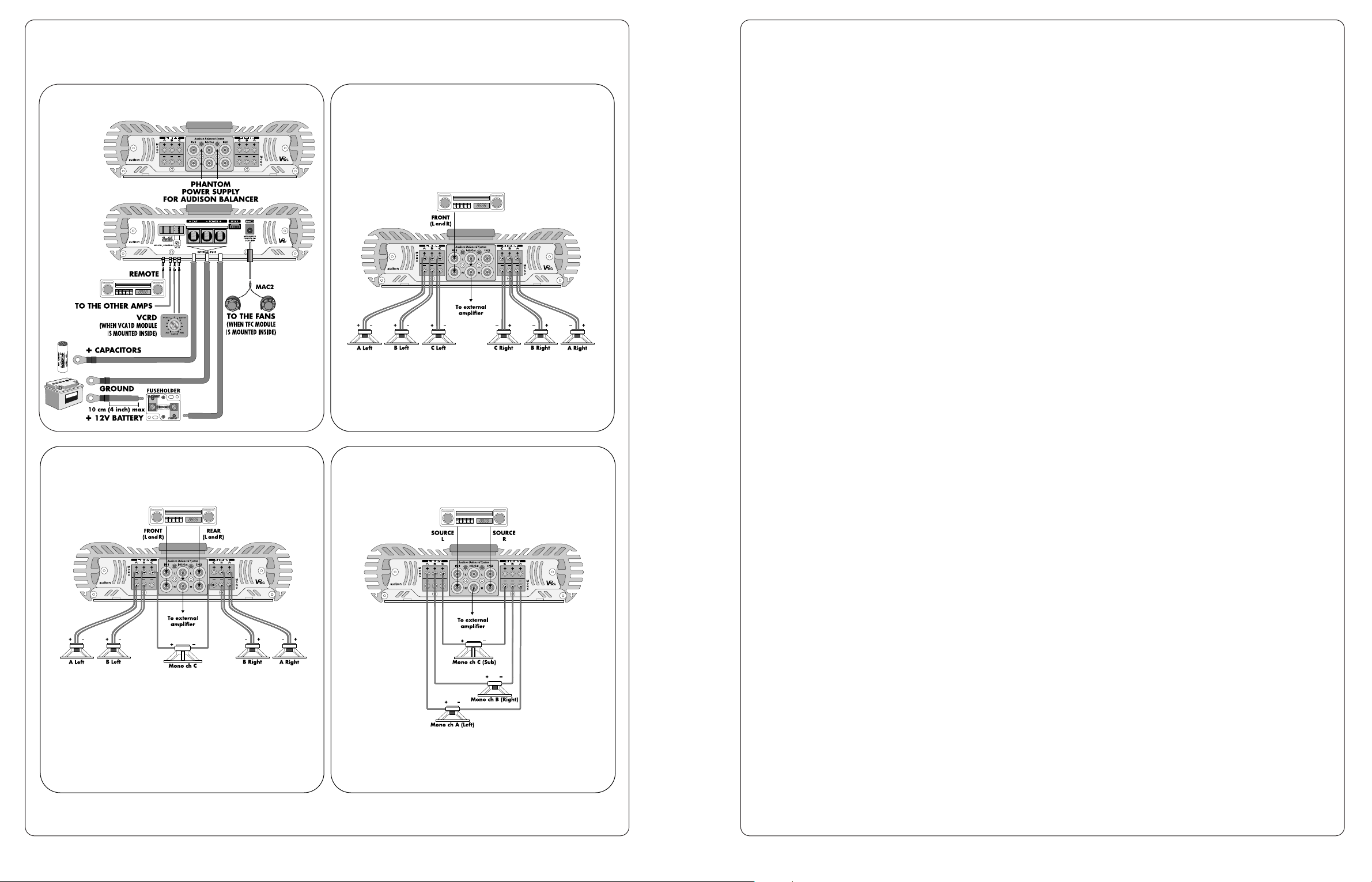
VRx6.420 connections
Inputs and outputs: connection with C
amplifiers in bridge
Power supply, remote and accessories Inputs and outputs:
stereo connection
Inputs and outputs: connection with A, B
and C amplifiers in bridge
- 68 -
Please see “Technical
Features” and “External
fuse size and location” in
order to choose the
proper external fuse.
Page 4
OBJECTIVES OF VRx PROJECT
VRx project was conceived in order to solve the problems which derive from the installation of a high quality
car audio system. The long and constant work made with professional installers and the use of the most
advanced, currently available technology allowed audison’s designers to attain totally new results in terms of
power, reliability and exceptional versatility above all. “VRx SYSTEM” derived from this: it is a complete line of
integrated electronic circuits made by amplifiers, active crossovers and signal processors, characterised by a
common conceptual system called Open Deck Construction.
Open Deck Construction
It’s the heart of VRx SYSTEM. It indicates the “totally open construction” of VRx SYSTEM. A sophisticated pre
section can accept several modules (MODULAR EXTENSIONS) which are put before the amplifiers and allow
their functioning configuration. The integration between amplifier and signal processors permits to reduce
signal paths as much as possible and to obtain performances which are not commonly attained through
separate units.
Modular Extensions
They are divided into:
• CONTROL EXTENSIONS: signal processing and control modules and cooling modules. They can be used
into all VRx.
• MULTICHANNEL EXTENSIONS: crossover modules which can be employed in one and two channel
amplifiers (VRx1 and VRx2). Multichannel VRx (VRx4 and VRx6) are already supplied with a sophisticated, reconfigurable crossover.
• COOLING DUCT EXTENSIONS: terminals and raccords which allow air ducting inside and outside the heat
sink, directing its flux in order to improve cooling. If cooling modules are not used, Cooling Duct Extensions
can be employed for esthetical purposes.
ABS ®- AUDISON BALANCED SYSTEM
All VRx amplifiers have balanced inputs and, if supplied with integrated crossover or Multichannel Extensions,
they also have balanced outputs. They use audison cable ABS connectors, which allow balanced connection
through an exclusive panel connector which is as big as standard RCA ones. They can accept signals up to 5V,
in order to be as compatible as possible with all sources which can be found into the market.
VRx AMPLIFIER
While developing VRx project, utmost attention was paid to the following aspects:
• dynamics, which involves power supply and amplifying stage
• reliability and, thus, protection and cooling
• sound quality.
VRx amplifiers have high power, which can guarantee very good dynamics even in car. In order to be able to do
this, power supply is oversized and has the same structure as HV series one.
Power supply is protected from overloads and excessive voltages (due to the car voltage controller breakdown or
to the battery charger fault, for instance). Protection against short circuits or against too low loads onto speakers
outputs were also introduced, as well as in case there is direct current on power signal.
Thermal protection is double: it traditionally controls heat sink temperature but also power supply transformers one.
In order to achieve the best sound quality, VRx use totally symmetrical, pure A class refined drivers made with
discrete components. These are mounted onto separate printed circuit boards with heat sink; this solution
guarantees optimal thermal stability.
Final stages use complementary inverted triplets of bipolar transistors. These components were judged better than
mosfets since they permit to obtain more linearity with the same power.
The accurate calibration of all these designing elements allowed the limitation of feedback factor below 15dB and,
thus, the achievement of outstanding sound features.
- 2 - - 67 -
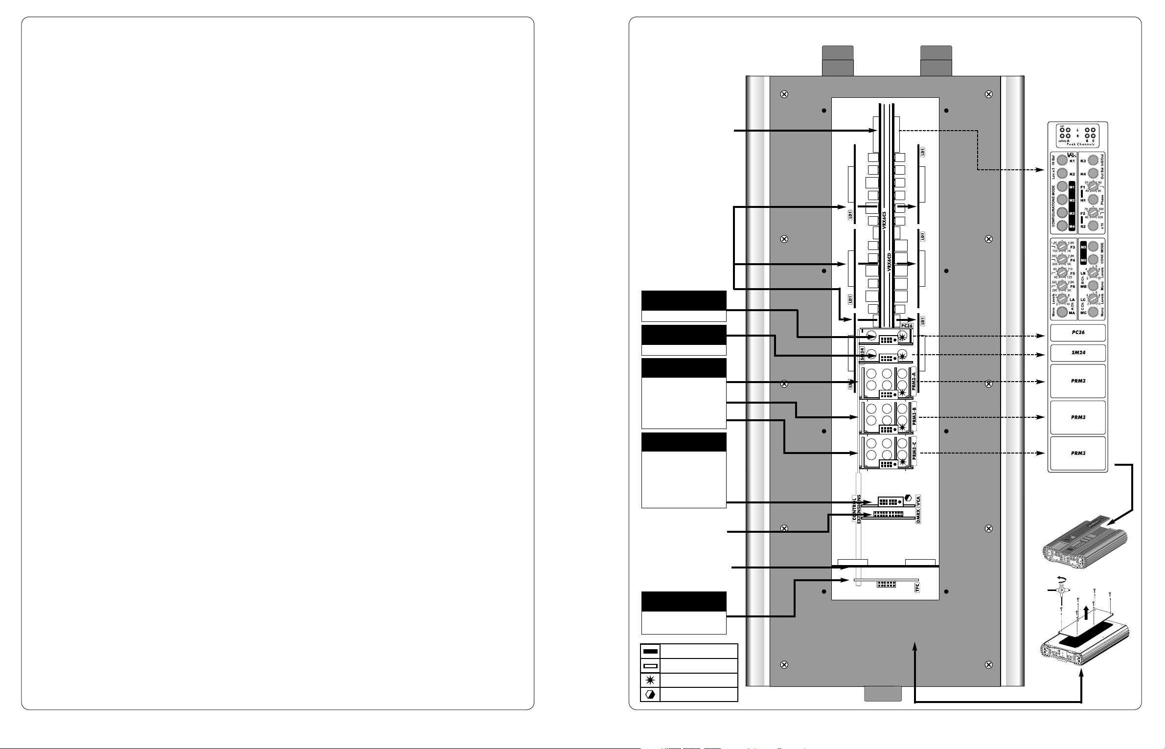
TPC VRx6 power supply
controller. It must not
be removed.
TFC
(supplied with MAC2)
CONTROL
EXTENSIONS
PRM3 for A channels
CONTROL
EXTENSIONS
DMRX socket for a
future extension. Do
not put any modules
into it.
Socket for:
- VCA1D, given
with VCRDK
CONTROL
EXTENSIONS
VCA
PRM3 for B channels
PRM3 for C channels
SM24
CONTROL
EXTENSIONS
PC36
CONTROL
EXTENSIONS
LD1 VRx6 driver stages.
They must not be
removed.
Canali A
Canali B
Canali C
VRx6.420
Controls under
wooden strip
BYP08 bridge: 4+4 Pins
Modular Extensions
Serial modules
BYP12 bridge: 6+6 Pins
VRX6CD-S VRx6
controls. They must not
be removed.
WHERE TO PUT MODULAR EXTENSIONS
Page 5
GENERAL FEATURES
Conformity with “E” norms
VRx models have a RF filter which makes them suitable to the new norms about radio-frequency disturbances
emission inside cars before any others. A “common mode”, adequately dimensioned filter choke was inserted
next to power supply input in order to prevent sudden voltage drops which commonly occur in similar circuit
typologies.
Thermal limiter onto transformers
A very effective protection circuit was put onto transformers to prevent them from exceeding temperatures
which might be dangerous for the amplifier integrity. This circuit intervenes by having VRx stop; the amplifier
will start to function again only after the necessary cooling and reset operation (on and off again) will have to
be carried out.
LNS (Line Noise Suppressor) circuit
LNS circuit allows the system low frequency disturbances rejection, reducing the ordinary noise due to car
electrical parts (alternator, electronic injection, etc.). It does not affect sound and is effective in most cases. The
special switch which is onto all models except VRx 6.420 (where it is not indicated since it is constantly active)
permits to check if its intervention is necessary in case there are several VRx configured in cascade.
TPC.2 (Twin Power Controller) power supply stage handling system
TPC.2 allows to increase power supply stage handling speed (10 times approx.). This implies higher available
impulsive power and lower stress of filter capacitors.
OCN (Off Current Null) and DVP (Damaging Voltage Protection) circuits
Thanks to OCN circuit, VRx models are the only ones to be in conformity with max absorption new standards
when amplifier is off. Their value (0.00005A) makes them be 10 times below the maximum allowed limit. DVP
circuit protects VRx amplifiers from voltage increases and electrostatic discharges.
Synchro-PWM power supply
Power supply stage consists of two totally separate and synchronised sections: one for positive and one for
negative voltages. It is therefore possible to satisfy the final stage current demands more promptly,
guaranteeing higher energy and speed with low frequencies.
Final stage driver modules: LD1.2 and DHF.1
Final stage driver modules (LD1.2 for VRx2-4-6; DHF.1 for VRx1) sum up all audison’s experience of amplified
sound characterisation. Subjected to continuous studies and improvements, they further increase linearity and
acoustic impact with low frequencies in the current VRx version.
DFL (Distortion Frequency Limiter) circuit
DFL circuit is a real electronic protection for speakers. It limits max distortion factor to 6% onto low frequencies
and to 2% onto high ones. This implies constant and systematic control onto all audio range and wide safety
margin for all speakers in the system.
Sub input (VRx6.420)
VRx6.420 PRE OUT output can be used as IN Sub input in order to use this model with the head units which
have a third preamplified output for the subwoofer, exploiting the amplifier internal filter.
RGP input stages protection
(Resettable Ground Protection)
RGP is an electronic protection able to detect high direct current passage onto input ground; it acts by putting
the device in “stand by” condition (safety). The main feature of this circuit is its being able to work even when
the amplifier is off, allowing the interruption of current passage towards input stages in case of power supply
transformers short circuit. It perfectly guarantees the system safety since it consists of several sensors.
Three way, big size terminal block
VRx terminal block can accept cables up to 2 gauge section. A third positive pole houses the external capacitor
(+C) which, thus, directly acts onto power supply voltage seen by the amplifier. This minimises voltage drop
and cable overheating. Fastening screws are protected by a polycarbonate door. Inside the terminal block there
is also a location for a strip fuse which can be inspected through the device bottom, that protects electronic
circuitry and external capacitor. This solution allows the installation to be cleaner and the terminal block-fuse
holder system to have 300A approx. max capacity.
- 3 -- 66 -
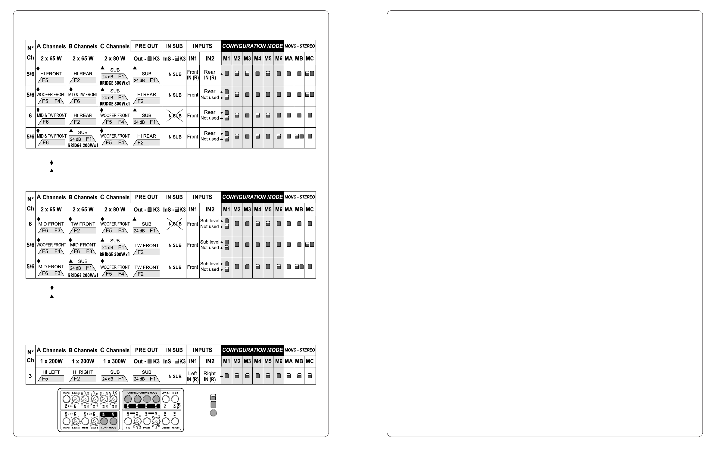
Front/Rear configurations
Multichannel Configurations
A, B and C bridged amplifiers configurations
= Released switch.
= Pushed switch.
IN2 = Sub level: Sub is driven by IN1 + IN2. Fader is used to adjust sub level.
IN2 = Not used: Sub and Front driven by IN1.
Channels are driven by PC36 (PC36 always takes signal from IN1)
Sub is driven by IN1 + IN2 NO FADING SUB (with active Constant Bass)
Note:
Channels are driven by PC36 (PC36 always takes signal from IN1).
Sub is driven by IN1 + IN2.
Note:
MA, MB and MC on position 2 (mono)
VRx6.420
=Switch involved
in configurations.
Page 6
- 65 -
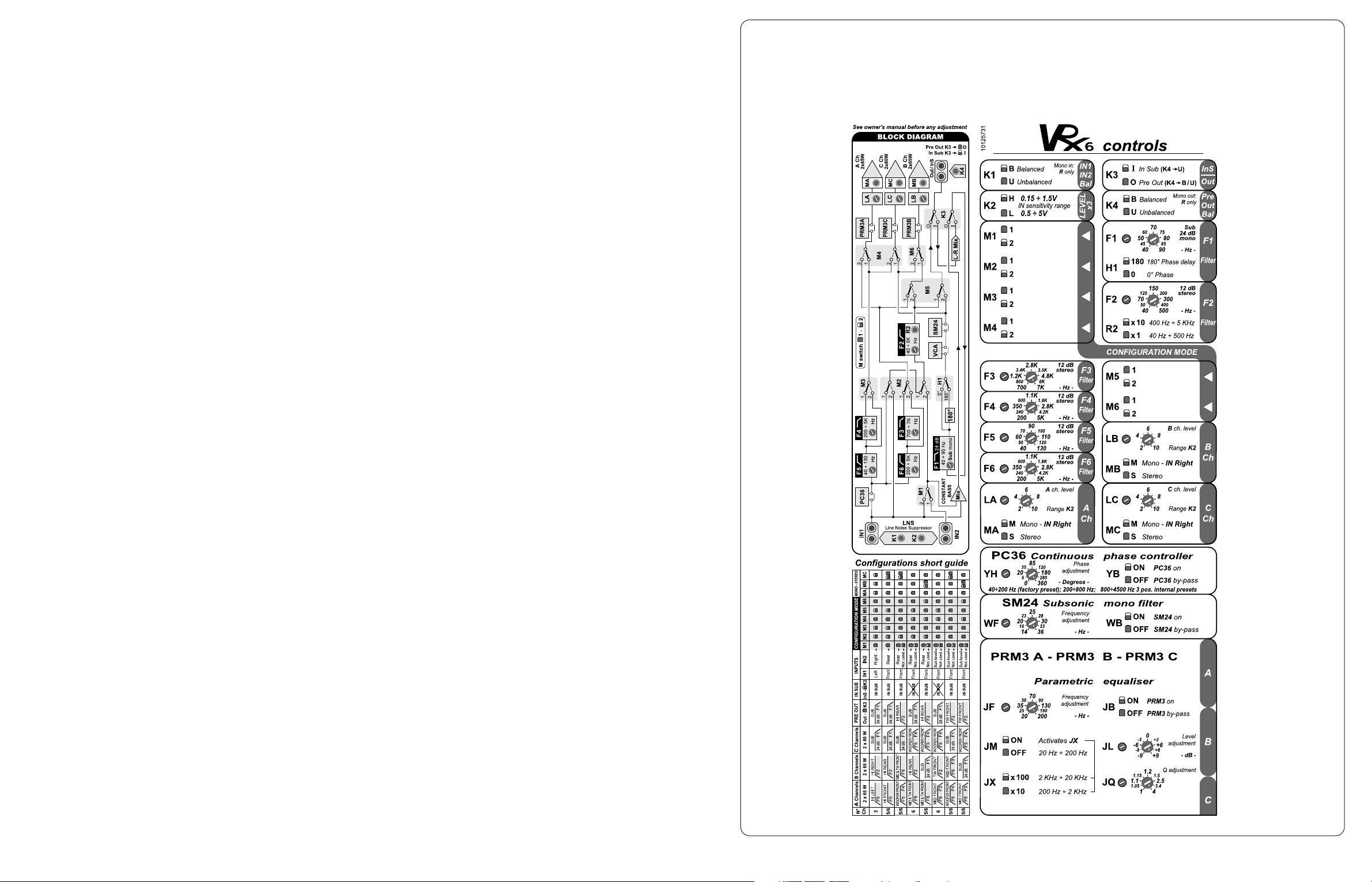
Short guide under wooden strip
It shows internal crossover, outputs configurations and controls meaning
VRx6.420
Page 7
- PRM3 stereo parametric equaliser
- SM24 24dB/oct. mono subsonic filter
- PC36 360˚ phase controller
- DSC1 sub dynamic control
- VCRDK digital remote volume control kit
(VCA1D module + VCRD adjuster)
- VCA1D VCA1D module VRx - BTX2
- MAC2 forced air modulated cooling system
(2 fans with spacers to put into Terminals and Raccords, plus TFC control module)
- BTX2 stereo balancer/preamplifier
- 5 -
VRx MODULAR EXTENSIONS:
CONTROL EXTENSIONS
WARNING!
Apply to Audison’s specialised installation centres for the installation and
configuration of modular extensions described in this section
2000
EDITION
K1 - Bal/Unbal inputs
switch.
K2 -It selects sensitivity
range of all inputs.
K3 - In Sub/Pre Out
switch. ABS sockets,
normally used for Pre
output, can be also
employed as additional
input for Sub.
K4 - Bal/Unbal switch for
PRE output. It is
possible to have a
balanced output
signal even with an
unbalanced input one.
Put K4 on B (Balanced)
only if K3 is on O (Out)
M1, M2, ..., M6 - Switches
to select the amplifier
functioning modes. M1,
M2 and M3 act on
crossover and on inputs
connection; M4, M5
and M6 act on outputs.
Please see the manual
in order to use them; it
indicates VRx6 main
functioning modes.
F1- Mono LO-PASS filter
for sub, 24dB/oct.
slope.
F2, F3, F4, F5, F6 - 12dB/oct. stereo crossover
filters. The pairs (F4, F5) and (F3, F6) form two
band-passes.
LA,LB, LC - Input sensitivity adjustment of A and
B amplifiers pairs respectively.
MA, MB, MC - Mono/Stereo switches of A, B and
C amplifiers respectively.
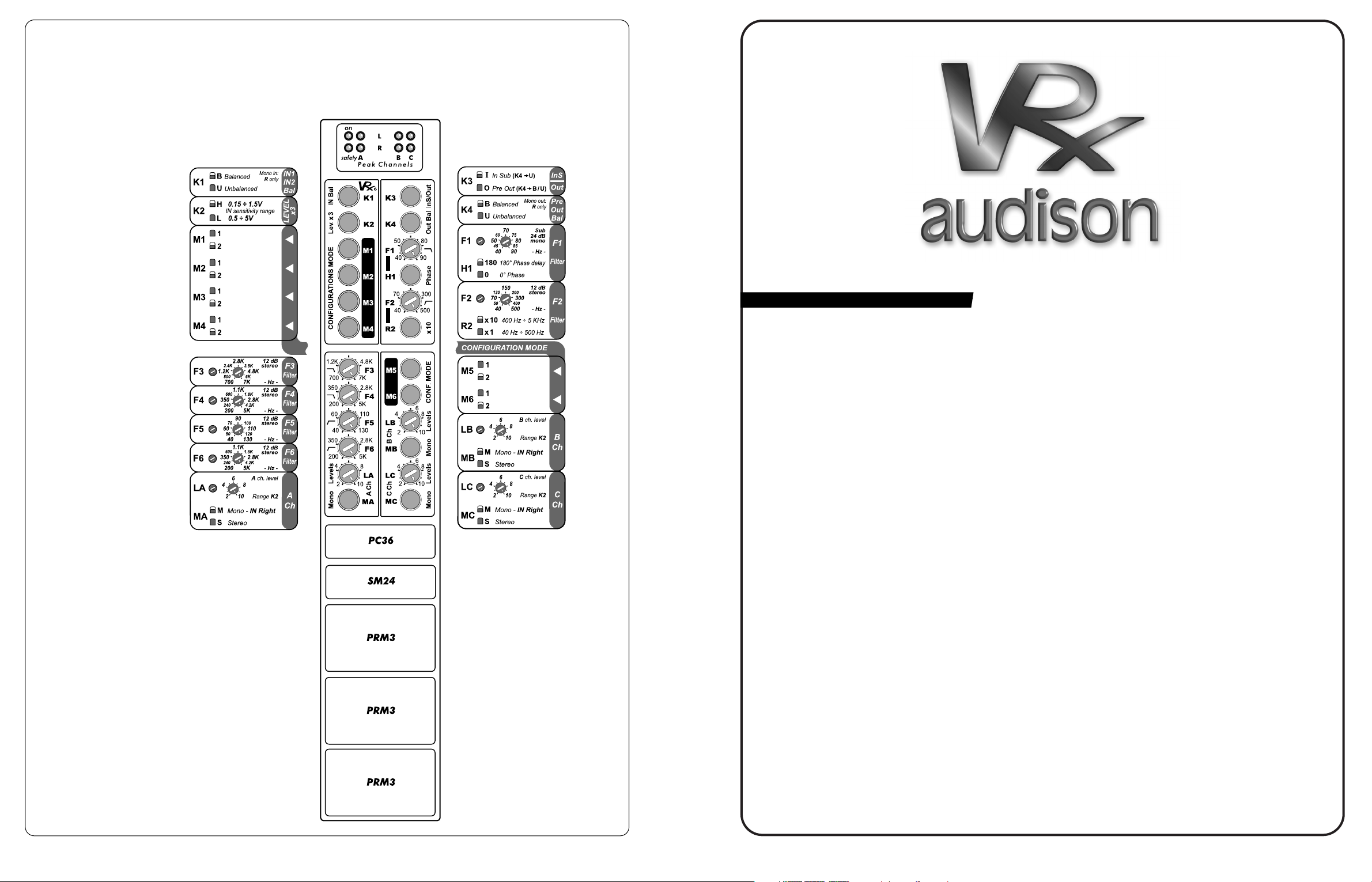
VRx6.420
Controls description
ON - Green led
It indicates the amplifier is on.
SAFETY - Red led
It indicates protection intervention:
excessively high temperature or
output anomalies (direct current,
short circuit or dangerously low load
impedance). Protection intervention
stops the amplifier functioning.
Switch the amplifier off; when
anomaly is eliminated, switch the
amplifier on again.
PEAK CHANNELS LA - LB - RA RB - Orange leds
They light up when one or more VRx
amplifiers are about to attain
distortion threshold. They are useful
to adjust inputs sensitivity.
- 64 -
Short guide
Leds
Controls under
wooden strip
Short guide
A Channels
B Channels
C Channels
Controls and functions
Page 8
- 6 - - 63 -
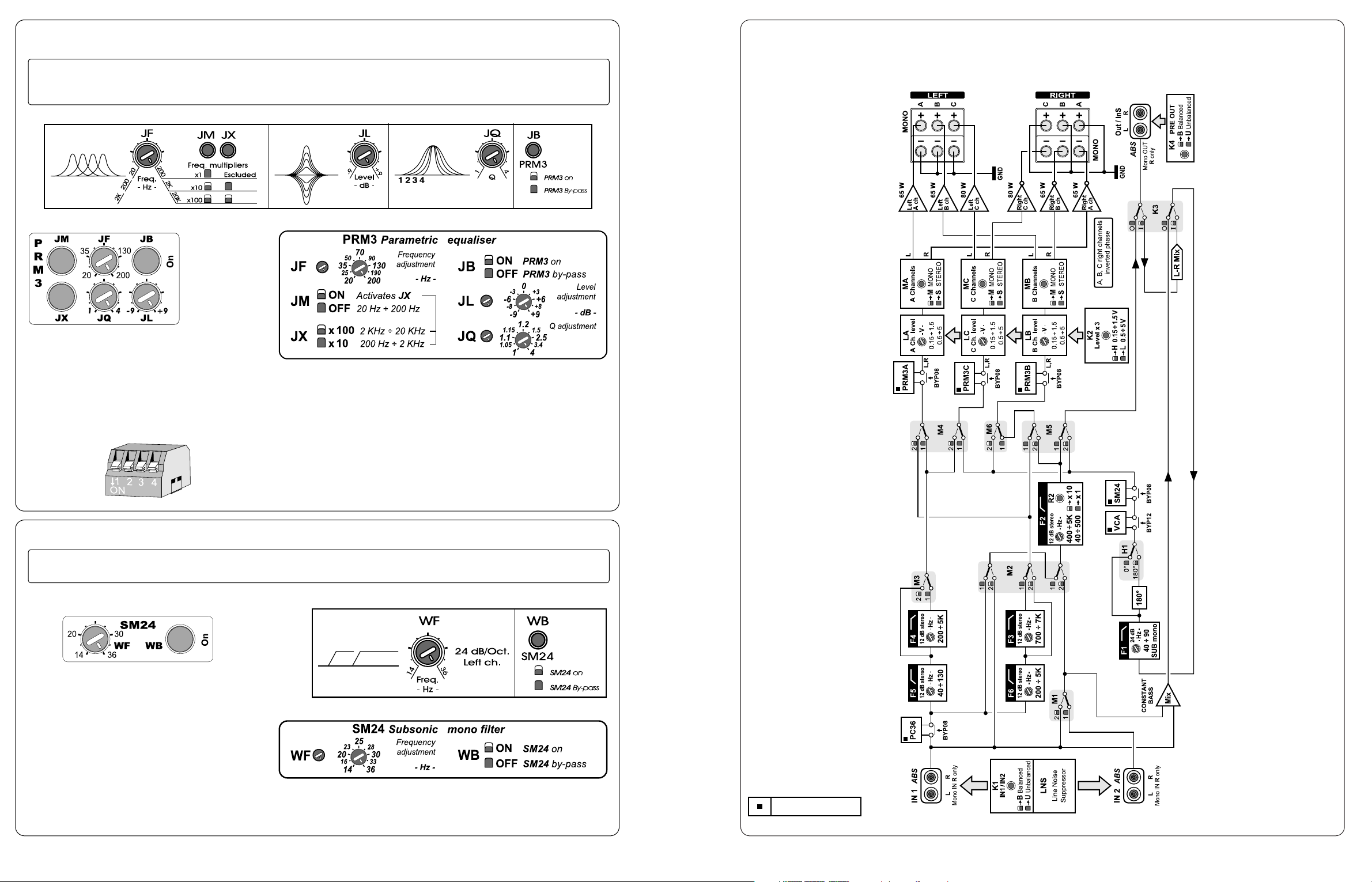
Block diagram
VRx6.420
Optional modules
Controls panel
Functions diagram
WF - Frequency adjustment.
WB - SM24 ACTIVE (ON)/BYPASS (OFF) switch.
Controls description
VRx1 and VRx2 amplifiers can use one PRM3
module; VRx4 amplifiers can use two; VRx6
amplifiers can use three. This allows the insertion
of a parametric equalisation on each way of a
multiamplified system made with VRx amplifiers.
Warning: There is a DIP Switch to be set on
ON into PRM3.1 modules.
DIP Switch
VRx Control Extensions PRM3
Stereo parametric
equaliser
Gain: ± 9 dB
Frequencies ranges: 20Hz÷200Hz; 200Hz÷2KHz; 2 kHz÷20KHz
Controls panel
Functions diagram
Q adjustment: 1÷4
Controls description
SM24 is monophonic since it was designed in
order to be used with subwoofer.
It only acts on the Right channel of
preamplified signal, therefore:
• the amplifier it drives must be configured in
mono;
• if its output is sent to an external amplifier
(possible solution with VRx4 and VRx6), only the
Right Channel of pre output must be used.
VRx Control Extensions SM24
Mono subsonic filter
Frequency range: 14 Hz ÷ 36 Hz
24dB/oct. HI-PASS
Short guide
Short guide
One band stereo parametric equaliser with
frequency, gain and bandwidth (Q) control.
Monophonic subsonic filter for subwoofer.
JF - Frequency adjustment.
JM - Switch for activating frequency ranges multiplier.
JB - Active (ON)/BYPASS (OFF) switch.
JX - Frequency ranges switch.
JL - Level adjustment.
JQ - Q adjustment.
Page 9
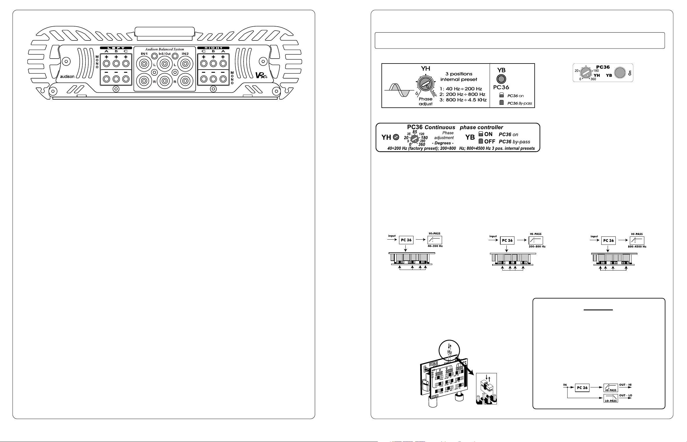
PC36 frequency range must be set according to the cut-off frequency chosen for HI-PASS filter it must be used with.
PC36 module is able to vary relative phase
between two ways of a multiamplified system. Its
purpose is to make the emission of a speakers
system, located in different places in car, more
homogeneous. Generally speaking, PC36
module allows you to put the HI-PASS filtered way with electronic crossover in phase with regards to the one which
is LO-PASS filtered in a bi-amplified system. It is possible to use two PC36 in a three way amplified system: one to
align tweeters with regards to midwoofers and one to align midwoofers with regards to subwoofer.
Used into VRx4 and VRx6, PC36 allows the front system phase alignment with regards to subwoofer. Applied into
VRx2 and VRx1, it permits to put all crosses of a multiamplified system in phase if it is used together with HI-PASS
sections of HL12, HL24, BH12 modules or with BAND-PASS sections of BH12.
Pre-select frequencies ranges through jumpers according
to cut-off frequencies of the HI-PASS filter it is used with.
PC36 is originally set on 40 ÷ 200 Hz.
- 7 -
VRx Control Extensions PC36
Frequencies ranges: 40Hz÷200Hz; 200Hz÷800Hz; 800Hz÷4,5kHz
Phase range: 0°÷360°
360˚ phase controller
Controls panel
Functions diagram
YH - Phase adjustment.
YB - Switch: PC36 ACTIVE (ON)/BYPASS (OFF).
Controls description
Short guide
Freq. range 40Hz÷200Hz
Freq. range 200Hz÷800Hz
Freq. range 800Hz÷4.5kHz
Analogue phase controller acting on the higher
frequencies of a multiamplified audio chain.
WARNING
The use of PC36 into VRx1 and VRx2 depends
on the installation of HL12, BH12, HL24
multichannel extensions, since PC36 acts only
on HI-PASS section.
Where PC36 acts:
VRx6.420
Technical features
POWER SUPPLY . . . . . . . . . . . . . . . . . . . . . . . . . . . . . . . . . . . . . . . . . . . . .11 ÷ 15 VDC
IDLING CURRENT . . . . . . . . . . . . . . . . . . . . . . . . . . . . . . . . . . . . . . . . . . .2.6 A
IDLING CURRENT WHEN OFF . . . . . . . . . . . . . . . . . . . . . . . . . . . . . . . . . . .< 0.04 mA
CONTINUOUS NOMINAL POWER Tol.: (+10%/-5%); 0.3% THD; 12 VDC
A,B,C stereo ch. on 4 Ohms . . . . . . . . . . . . . . . . . . . . . . . . . . . . . .2x65W + 2x65W + 2x80 (RMS)
CONTINUOUS POWER 6 CHANNELS Tol.: (+10%/-5%); 1% THD; 12.6 VDC
A,B,C stereo ch. on 4 Ohms . . . . . . . . . . . . . . . . . . . . . . . . . . . . . . 2x75W + 2x75W + 2x85 (RMS)
CONTINUOUS POWER 6 CHANNELS Tol.: (+10%/-5%); 1% THD; 13.8 VDC
1) A,B,C stereo ch. on 4 Ohms . . . . . . . . . . . . . . . . . . . . . . . . . . . .2x75W + 2x75W + 2x85 (RMS)
2) A,B,C stereo ch. on 2 Ohms . . . . . . . . . . . . . . . . . . . . . . . . . . . .2x120W + 2x120W + 2x150 (RMS)
3) A,B stereo ch. on 4 Ohms, C stereo ch. on 2 Ohms . . . . . . . . . . .2x75W + 2x75W + 2x165 (RMS)
4) A,B stereo ch. on 4 Ohms, C stereo ch. on 1 Ohm . . . . . . . . . . . .2x75W + 2x75W + 2x250 (RMS)
CONTINUOUS POWER 5 CHANNELS Tol.: (+10%/-5%); 1% THD; 13.8 VDC
5) A,B stereo ch. on 4 Ohms, C bridged ch. on 4 Ohms . . . . . . . . . .2x75W + 2x75W + 1x330 (RMS)
6) A,B, stereo ch. on 4 Ohms, C bridged ch. on 2 Ohms . . . . . . . . .2x75W + 2x75W + 1x500 (RMS)
7) A,B stereo ch. on 2 Ohms, C bridged ch. on 2 Ohms . . . . . . . . .2x110W + 2x110W + 1x430 (RMS)
CONTINUOUS POWER 3 CHANNELS Tol.: (+10%/-5%); 1% THD; 13.8 VDC
8) A,B,C bridged ch.on 4 Ohms . . . . . . . . . . . . . . . . . . . . . . . . . . .1x240W + 1x240W + 1x300 (RMS)
9) A,B bridged ch. on 4 Ohms, C bridged ch. on 2 Ohms . . . . . . . . .1x220W + 1x220W + 1x430 (RMS)
THD DISTORTION (1 kHz; 90% Nominal Power) . . . . . . . . . . . . . . . . . . . . . .0.02%
IMD DISTORTION (90% Nominal Power) . . . . . . . . . . . . . . . . . . . . . . . . . . . .0.04%
BANDWIDTH (-3dB; Nominal Power) . . . . . . . . . . . . . . . . . . . . . . . . . . . . . .2 Hz ÷ 70 kHz
S/N RATIO (A weighed - 1 VRMS input) . . . . . . . . . . . . . . . . . . . . . . . . . . . . .100 dBA
REMOTE IN . . . . . . . . . . . . . . . . . . . . . . . . . . . . . . . . . . . . . . . . . . . . . . . .7 ÷ 15 VDC
REMOTE OUT . . . . . . . . . . . . . . . . . . . . . . . . . . . . . . . . . . . . . . . . . . . . . .12 VDC - 150 mA
INPUT SENSITIVITY (high) . . . . . . . . . . . . . . . . . . . . . . . . . . . . . . . . . . . . . .0.15 ÷ 1.5 VRMS
INPUT SENSITIVITY (low) . . . . . . . . . . . . . . . . . . . . . . . . . . . . . . . . . . . . . . .0.50 ÷ 5.0 VRMS
INPUT IMPEDANCE . . . . . . . . . . . . . . . . . . . . . . . . . . . . . . . . . . . . . . . . . .15 kOhms
LOAD IMPEDANCE (stereo) ch.A and ch.B . . . . . . . . . . . . . . . . . . . . . . . . . . .8 - 4 - 2 Ohms
LOAD IMPEDANCE (bridged) ch.A and ch.B . . . . . . . . . . . . . . . . . . . . . . . . .8 - 4 Ohms
LOAD IMPEDANCE (stereo) ch.C . . . . . . . . . . . . . . . . . . . . . . . . . . . . . . . . .8 - 4 - 2 -1 Ohm
LOAD IMPEDANCE (bridged) ch.C . . . . . . . . . . . . . . . . . . . . . . . . . . . . . . . .8 - 4 - 2 Ohms
SIZE (W x H x D) mm. . . . . . . . . . . . . . . . . . . . . . . . . . . . . . . . . . . . . . . . . .240 x 64 x 585
SIZE (W x H x D) inches . . . . . . . . . . . . . . . . . . . . . . . . . . . . . . . . . . . . . . . .9.4 x 2.5 x 23
INTERNAL FUSE . . . . . . . . . . . . . . . . . . . . . . . . . . . . . . . . . . . . . . . . . . . . . 80A
ABSORBED CURRENT AT MAXIMUM MUSICAL POWER - EXTERNAL FUSE CHOICE
13.8V - configuration 1) . . . . . . . . . . . . . . . . . . . . . . . . . . . . . . . . . . . . . . .33A
13.8V - configurations 2) and 8) . . . . . . . . . . . . . . . . . . . . . . . . . . . . . . . . .64A
13.8V - configurations 3) and 5) . . . . . . . . . . . . . . . . . . . . . . . . . . . . . . . . .47A
13.8V - configurations 4) and 6) . . . . . . . . . . . . . . . . . . . . . . . . . . . . . . . . .66A
13.8V - configurations 7) and 9) . . . . . . . . . . . . . . . . . . . . . . . . . . . . . . . . .80A
Measures were realised through a test-set consisting of Rohde & Schwarz UPD audio analyser, HP 6453A power supply
(200A continuous) and 14F capacitive booster made with audison cable Superfarad capacitors.
Please always choose a fuse of equal or slightly higher value (max 10%) than indicated.
Note:
The use of MAC2 cooling system is strongly recommended when the amplifier is employed at full power with 1 Ohm
stereo or 2 Ohm bridged loads.
- 62 -
Page 10
- 8 -
VRx6.420
2000
EDITION
- 61 -
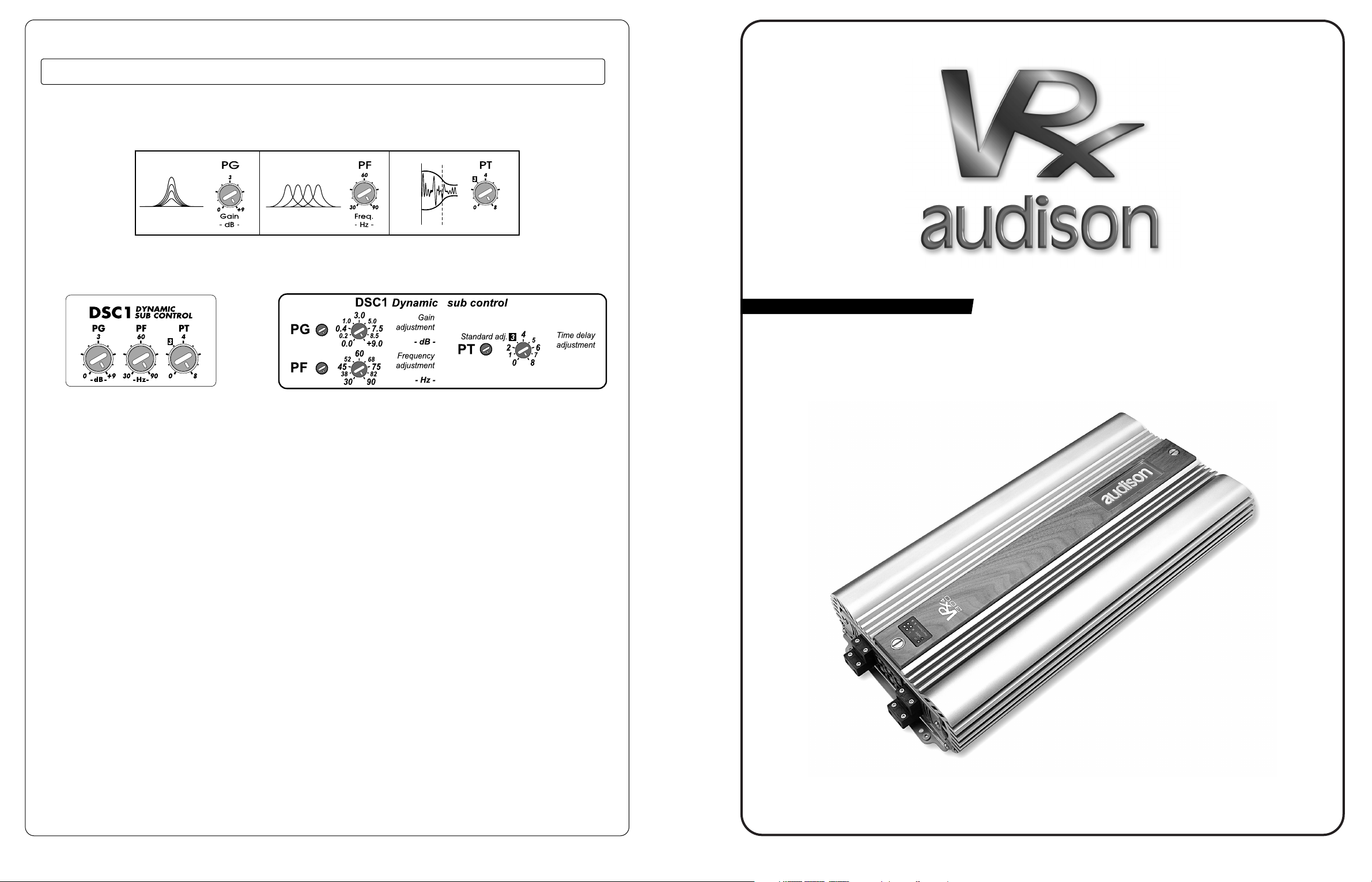
Dynamic Sub Control
Controls panel
VRx Control Extensions DSC1
Dynamic Sub Control
Functions diagram
Controls description
PG-
Gain adjustment
PF -Frequency adjustment
PT -Time delay adjustement
Short guide
It is a parametric pole which
permits to make up for
subwoofers volumetric
inadequacy by having their low
frequencies gain extent and
impact.
DSC1 adjusts its intervention by
increasing it at low signal levels
and avoiding the amplifier
saturation. Its controls allow to
choose frequency, intervention
and gain.
Page 11
It consists of a cooling group formed by a pair of fans with spacers and by a temperature control module (TFC)
to put inside VRx amplifiers.
The fans group is placed inside Raccords and Terminals and adapted to several lengths through spacers. VRx
amplifiers have a power supply connector dedicated to the cooling group under the power supply terminal blocks
panel. Raccords and Terminals act as ducts for cooling air and have the esthetical function of covering connection
cables. One terminal (TRM4, TRM6) with MAC2 kit is enough for the cooling system correct functioning. If you like
to put two VRx one after the other, you have to use a suitably long
Raccord (RC08, RC10, RC12)
which, if necessary, can also be
supplied with MAC2, installed
into the second VRx. The end of
the second VRx (inputs and warm
air output side) is able to accept
another Terminal (TRM4, TRM6) for
esthetical reasons. Raccords and
Terminals are chosen according to the size
of used cables and connectors, while the installation of one or
more MAC2 depends on VRx amplifiers configuration.
VRx Control Extensions MAC2
Forced air cooling system
- 9 -
System temperature control kit.
Fans group
VCRDK
It consists of VCRD adjuster and
of VCA1D, a high performances
digital control module. It can be
used to adjust the volume of sub
or of every VRx amplifier in the
system.
If it is installed into BTX2,
it permits to realise Master
Volume Control. Thanks to a
single VCRD adjuster connected
to the main BTX2 (Master),
supplied with VCA1D module
(VCRKD kit), it is possible to
adjust the volume of other stereo ways through as many secondary BTX2 (Slave) connected in cascade and supplied
with VCA1D modules. VCA1D modules are available also individually. Master Volume Control configuration
is necessary when you want to have volume independent general adjustment in multichannel systems for Front, Rear
and Sub outputs of head units supplied with them. The control microprocessor permits to store and recall a level;
this function is useful to keep the reference calibration in a multiamplified system, for instance. If the latter totally
consists of VRx1 or VRx2 amplifiers, the installation of one VCRDK for every amplifier would allow the level
adjustment of each way of the system.
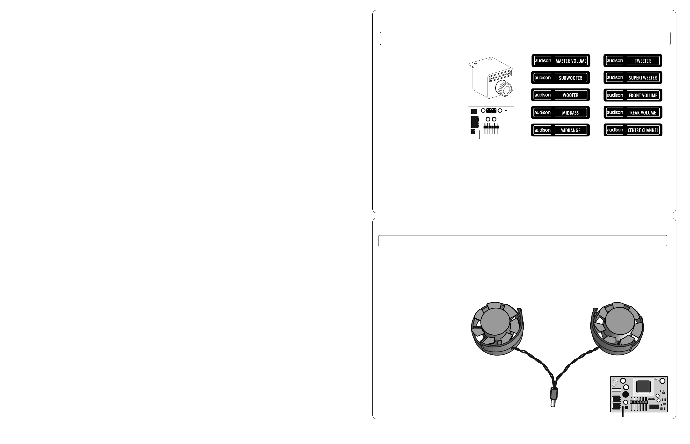
Some stickers allow VCRD customisation according to its function. It is also
possible to remove its housing in order to easily mount it behind a panel, while VCRD front panel stays visible.
VRx Control Extensions VCRDK and VCA1D
Digital remote volume control kit
VCRD
VCA1D
Kit for sub remote volume control, supplied
with VCA (Voltage Controlled Amplifier)
with digital control.
TFC module
Page 12

4
TRM4 and TRM6
INSTRUCTIONS
Put the Terminal or the Raccord onto a flat surface. (As far as Terminals are concerned, the side with grilles must
be facing upwards). Remove the front plate fixed through four screws by using multispanner supplied with the
devices (pict. 1 and 2). Place the fans groups onto the flat surface and push them in order to insert them inside the
extension body you are using, so that the fans group support guides snap into the slots (pict. 3).
Warning!: Do not push hard onto the fans wheel while mounting the fans group.
Fans group insertion inside Terminals and Raccords
1
2
3
After inserting the fans, mount
Terminals front plate back again
(pict. 4). If parts were assembled in
the right way, the fans wheels will
be in the same side as the grilles of
the plate itself.
TRM4 and TRM6
TRM4 and TRM6
TRM4 and TRM6
TRM6
General procedure for insertion inside Raccords
Remark for TRM4:
Do not turn the Terminal body while
mounting it. Its correct direction is
when the screw in the wooden strip
is closer to the flat surface the
terminal lies onto (pict. 2).
Remark for TRM6:
Insert the special spacers inside TRM6 in
order to avoid air flux dispersion by making
them slide onto the terminal proper slots
until they touch the fans.
Remark for Raccords:
Insert the fans and a sufficient
number of spacers into the
Raccord by making them slide
onto the proper slots, in order
to avoid air flux dispersion. The
last spacer must always be a
Terminal Spacer.
General procedure for insertion inside Terminals
- 10 -
VRx4.300 connections
Inputs and outputs:
bridge connection
Power supply, remote and accessories Inputs and outputs:
stereo connection
Inputs and outputs:
Front + Sub
- 59 -
Please see “Technical
Features” and “External
fuse size and location” in
order to choose the
proper external fuse.
Page 13

VRx Control Extensions BTX2
- 11 -
PHANTOM
power supply.
ON led.
BTX2
saturation led.
Gain switch.
Stereo balancer/preamplifier with audison
ABS system.
Master/Slave configuration of BTX2 devices with VCRD. SDA
and SCL outputs (serial OUT) of the main BTX2 (Master) must
be connected to VCR contacts of the secondary BTX2 (slave).
Stereo balancer/preamplifier
PH450
PH150(150cm)
and
PH650(650cm)
are available in
audison cable
line, besides
PH450(450cm)
Contacts for connecting VCRD adjuster. In Master/Slave
configuration of BTX2 devices with VCRD, these contacts
become Serial IN input for the secondary BTX2 (slave).
NOTE:
It is necessary to insert an ABS JACK (audison cable) in order to get a balanced signal. It is
possible to have an unbalanced signal by inserting a standard PIN RCA into ABS sockets. In
this case, output voltage value decreases; it can be increased again through GAIN switch.
ABS balanced outputs (see NOTE).
RCA unbalanced inputs.
Front panel Rear panel
FEATURES
BTX2 is a device which allows you to change a pre output of an ordinary head unit into a balanced output with
audison ABS system. In this way it is possible to realise an ABS balanced connection between signal source and
amplifier input by using audison cable ABS extensions.
BTX2 has got phantom power supply: it is therefore necessary to connect it to
audison VRx amplifiers proper output through PH450 cable (given with BTX2).
BTX2 has a three-step gain control, in order to interface with various sources.
A led indicates outputs saturation (clipping). BTX2 allows also Remove Volume
Control function, which permits to adjust the level of a stereo or a mono line. In
order to activate this function, you need to use the VCR
(Remote Volume Control) kits: VCRDK.
SDA SCL
B
T
X
2
5 VRMS max
- 58 -
TPC VRx4 power
supply controller. It
must not be removed.
TFC
(supplied with MAC2)
CONTROL
EXTENSIONS
PRM3 for A channels
CONTROL
EXTENSIONS
DMRX socket for a
future extension. Do
not put any modules
into it.
Socket for:
- VCA1D, given
with VCRDK
CONTROL
EXTENSIONS
VCA
PRM3 for B channels
SM24
CONTROL
EXTENSIONS
PC36
CONTROL
EXTENSIONS
LD1 VRx4 driver
stages. They must
not be removed.
Canali A
Canali B
VRx4.300
Controls under
wooden strip
BYP08 bridge: 4+4 Pins
Modular extensions
Serial modules
BYP12 bridge: 6+6 Pins
VRX4CD-S VRx4
controls. They must
not be removed.
WHERE TO PUT MODULAR EXTENSIONS
Page 14

24dB/oct. Mono SUB filter slope configurations
VRx4.300
- 57 -
S3 (12-24dB/oct. SUB filter slope switch) =
K3 (MONO/STEREO switch of A channels) =
2 INPUTS: IN1 Front L and R inputs, IN2 Rear L and R inputs; non fading sub.
1 INPUT: IN L and R inputs, IN2 not used; sub mix R+L.
4
SUB MONO 24 dB
F1
HI FRONT
Power: 75 W + 75 W
Filter
Bypass
40 Hz ÷ 5 kHz
B
1
F4
HI REAR
Filter
Bypass
40 Hz ÷ 5 kHz
B4
40 Hz ÷ 500 Hz
N° Ch “A” amps. Ch “B” amps. PREAMPLIFIED
MM
Switch
config.
STEREO loudspeakers outputs
Power
Outputs
Signal out on RIGHT ch.
(LEFT not used)
OM
N° Ch “A” amps. Ch “B” amps. PREAMPLIFIED
MM
Switch
config.
STEREO
loudspeakers outputs
Power
Outputs
3
STEREO line outputs
F1
HI FRONT
40 Hz ÷ 5 kHz
B
1
F4
HI REAR
40 Hz ÷ 5 kHz
B
4
OM
SUB MONO 24 dB
MONO
loudspeakers outputs
K6=
K6=
2 INPUT: IN1 i
nput Front L e R, IN2 input Rear L e R; non fading sub.
1 INPUT: IN1 input L e R, IN2 not used; sub mix R+L.
K6 =
K6 =
N°
2
Ch “A” amps.
Left section
Ch “B” amps.
Right section
PREAMPLIFIED
MM
Switch
config.
MONO loudspeakers outputs
Power
Outputs
F
1
HI-PASS
MONO line outputs
(LEFT not used)
Filter
Bypass
40 Hz ÷ 5 kHz
B
1
F
4
HI-PASS
Filter
Bypass
40 Hz ÷ 5 kHz
B
4
SUB MONO 24dB
F3
40 Hz ÷ 500 Hz
OM
INPUTS: use IN1 (R) for Left ch, use IN2 (R) for Right ch.K6 =
(RIGHT)
K4 (MONO/STEREO switch of B channels) =
R3 (F3 x 1/x10 LO-PASS frequency switch) =
S3 (12-24dB/oct. SUB filter slope switch) =
K3 (MONO/STEREO switch of A channels) =
K4 (MONO/STEREO switch of B channels) =
R3 (F3 x 1/x10 LO-PASS frequency switch) =
S3 (12-24dB/oct. SUB filter slope switch) =
K3 (MONO/STEREO switch of A channels)=
K4(MONO/STEREO switch of B channels
) =
F3
F
3
with active Constant Bass
*
*
*
40 Hz ÷ 500 Hz
Power: 250W
Power: 75 W + 75 W
Filter
Bypass
Filter
Bypass
Power: 75 W + 75 W
Power: 250 WPower: 250 W
Page 15

* Warning: Using B channels in Mono (K4 = ) with 12dB/Oct. filter, signal for sub depends on Right input. If
you move Balance onto the Left channel in this condition, sub will not play. It is therefore necessary to set B
channels in stereo (K4 = ) in order to obtain the sum between Left and Right.
- HL12 12 dB HI/LO-PASS crossover
- BH12 12 dB BAND/HI-PASS crossover
- LM24 24 dB LO-PASS MONO crossover
- HL24 12/24 dB HI/LO-PASS crossover
- BSA1 stereo balanced pre out repeater
VRx MODULAR EXTENSIONS:
MULTICHANNEL EXTENSIONS
WARNING!
Apply to Audison’s specialised installation centres for the installation and
configuration of modular extensions described in this section
(only for models: VRx1.500, VRx2.150, VRXx2.250 and VRx2.400)
2000
EDITION
- 13 -- 56 -
K4 (MONO/STEREO switch of B channels) =
Power: 250W (Mono) 75W+75W (Stereo)
N°
4
Ch “A” amps. Ch “B” amps. PREAMPLIFIED
MM
Switch
config.
STEREO loudspeakers outputs
Power
Outputs
F1
MID-HI FRONT WOOFER FRONT
40 Hz ÷ 130 Hz
F3
40 Hz ÷ 5 kHz
4
HI REAR
4
WOOFER FRONT
3/4
SUB
F3
40 Hz ÷ 5 00 Hz
SUB
F3
40 Hz ÷ 5 00 Hz
STEREO line outputs
Filter
Bypass
40 Hz ÷ 5 kHz
B1
F1
MID-HI FRONT
Power: 75 W + 75 W
Filter
Bypass
40 Hz ÷ 5 kHz
B1
F4
HI-REAR
Power: 75 W + 75 W
Filter
Bypass
40 Hz ÷ 5 kHz
B4
F1
HI FRONT
Power: 75 W + 75 W
Filter
Bypass
40 Hz ÷ 5 kHz
B1
F
1
HI FRONT
Filter
Bypass
40 Hz ÷ 5 kHz
B
1
F4
HI REAR
Power: 75 W + 75 W
Filter
Bypass
40 Hz ÷ 5 kHz
B4
F
4
HI REAR
Filter
Bypass
40 Hz ÷ 5 kHz
B4
F4
Filter
Bypass
40 Hz ÷ 5 kHz
B4
F2
40 Hz ÷ 130 HzF340 Hz ÷ 5 kHz
F2
OM
N°
2
Ch “A” amps.
Left section
Ch “B” amps.
Right section
PREAMPLIFIED
MM
Switch
config.
MONO loudspeakers outputs
Power
Outputs
F1
HI-PASS
Power: 250 W
MONO line outputs
Filter
Bypass
40 Hz ÷ 5 kHz
B1
F4
HI-PASS
Power: 250 W
Filter
Bypass
40 Hz ÷ 5 kHz
B4
SUB
F3
40 Hz ÷ 500 Hz
OM
K6=
K6=
S3 (12-24dB/oct. SUB filter slope switch) =
K3 (MONO/STEREO switch of A channels ) =
INPUTS: use IN1 (R) for Left ch, use IN2 (R) for Right ch.K6 =
K4 (MONO/STEREO switch of B channels) =
S3 (12-24dB/oct. SUB filter slope switch) =
K3 (MONO/STEREO switch of A channels ) =
Power: 75 W + 75 W
VRx4.300
*
B1=F1 filter BYPASS
B4=F4 filter BYPASS
F1= HI-PASS filter
F2= HI-PASS filter of woofer BAND-PASS
(MM= ), it does not work if MM=
F3= LO-PASS filter of woofer BAND-PASS
(MM= ) or subwoofer LO-PASS
filter (MM= )
F4= HI-PASS filter
= Released switch
= Pushed switch
12dB/oct. SUB filter slope configurations
Power: 75 W + 75 W
Power: 75 W + 75 W
2 INPUTS: IN1 Front L and R inputs, IN2 Rear L and R inputs; non fading sub.
1 INPUT: IN1 L and R inputs, IN2 not used.
Page 16

Module description
Filter slope: 12dB/oct. Continuous adjustment through 2 steps: 40÷500Hz; 400÷5000Hz. HL12
adds one ABS PRE output to the amplifier it is installed into.
Features
Installed into VRx1 or VRx2, HL12 permits to drive stereo/mono SUB section with 12dB cut. HI-PASS output permits to
drive an amplifier without crossover (non independent crossover frequency). The BYPASS output of the first amplifier
allows the independent control of HI-PASS frequencies by adding a VRx2 supplied with another HL12. In combination
with another VRx2 supplied with
HL12, the use of HI-PASS output
also allows the creation of BANDPASS sections.
Uses
HL12 is a very versatile and
polyvalent module. It can be used
in the simplest bi-amplified
systems, in REAR section or in
high performances multiamplified
systems. According to VRx
philosophy, it is the “factotum”
you have to keep at hand,
because it is always possible to
filter a system through it. It is the
ideal partner for VRx2 and LM24.
VRx1 - VRx2 Multichannel Extensions HL12
Frequencies ranges: 40 Hz ÷ 500 Hz; 400 Hz ÷ 5 kHz
12dB/oct. HI-PASS/LO-PASS
Controls
panel
Short guide
Sticker to put onto
VRx1 and VRx2
short guide
together with
Block Diagram one
Block diagram
Ke - BALANCED (B)/UNBALANCED (U) switch for PRE OUT output.
Fe - 12dB/oct. HI/LO-PASS crossover frequency adjustment.
Re - Fe x 10 (x10)/x1 (x1) frequency switch.
He - 0˚ (0˚)/180˚ (180˚) phase shifting switch for amplifier output.
Se - HI-PASS (H)/LO-PASS (L) switch for PRE OUT output.
Be - BYPASS (B)/FILTERED (F) switch for PRE OUT output.
Controls description
- 14 -
OUT PRE-OUT
Se
HI/LO-PASS
Be
BYPASS
Fe
Bypass
Bypass
Fe
Fe
Fe
F
e
F
e
Crossover module for VRx1 and VRx2, with
non independent HI/LO-PASS crossover
frequency.
12 dB/oct. 12 dB/oct.
12 dB/oct.
12 dB/oct.
12 dB/oct.
12 dB/oct.
Crossover
Possible
configurations
- 55 -
Short guide under wooden strip
It shows internal crossover, outputs configurations and controls meaning
VRx4.300
Page 17

Module description
BAND/HI-PASS section (Lower frequency): 12dB/oct. filter slope. Variable frequency between 40Hz and 2kHz,
through 2 steps: 40Hz÷280Hz; 280Hz÷2kHz. Continuous adjustment.
BAND/LO-PASS (Higher frequency) and HI-PASS section: 12dB/oct. filter slope. Variable frequency between 150
and 5000Hz. Continuous adjustment. BH12 adds one ABS PRE output to the amplifier it is installed into.
Features
It allows the extension to higher frequency ranges in multiamplified systems. Together with HL12, it permits the
frequencies total independent control.
Uses
BH12 is especially designed for multiamplification. Its high internal complexity makes its use simple and evident.
It is VRx2 partner and it is ideal for HL12 and LM24.
VRx2 Multichannel Extensions BH12
Crossover module for VRx2 with BAND-PASS filter
with independent adjustments and non
independent HI-PASS crossover frequency.
- 15 -
OUT PRE OUT
Be
BYPASS
F1
Bypass
Possible
configurations
Crossover
F1 frequencies ranges: 40 Hz ÷ 280 Hz; 280 Hz ÷ 2 kHz
12dB/oct. BAND-PASS/HI-PASS
Controls
panel
Short guide
Sticker to put
onto VRx2 short
guide together
with Block
Diagram one
Block diagram
Ke - BALANCED (B)/UNBALANCED (U) switch for PRE OUT output.
F1 - 12dB/oct. BAND-PASS lower frequency adjustment.
R1 - F1 x 7 (x7)/x1 (x1) frequency switch.
F2 - 12dB/oct. BAND-PASS higher frequency and 12dB/oct.
HI-PASS lower frequency adjustment.
He - 0˚ (0˚)/180˚ (180˚) phase shifting switch for amplifier output.
Be - BYPASS (B)/HI-PASS (F) switch for PRE OUT output.
Controls description
F2 frequency range:150 Hz ÷ 5 kHz
F1
F2
F2 F2
12 dB/oct.
12 dB/oct.
12 dB/oct.
K1-Bal/Unbal inputs switch.
K2-LNS circuit ON/OFF switch
for line noise suppression.
K3, K4 - Mono / Stereo
switch for A and B
amplifiers pairs
respectively.
K5-It selects sensitivity
range of all inputs.
LA, LB - Input sensitivities
adjustment of A and
B amplifiers pairs
respectively.
K6-1/2 inputs pairs
switch.
K7-Bal/Unbal switch for
PRE output. It is
possible to have a
balanced output
signal even with an
unbalanced input one.
F2 -Filter used only in
Multichannel mode in
order to have a
BAND-PASS.
F3 -LO-PASS filter which
can be set at 24dB/oct.
slope ONLY in mono
configuration,
40-500 Hz range, for
subwoofer (F/R mode).
MM and OM - They select internal crossover
functioning modes. Please see VRx block
diagram and uses in order to understand
how they act.
Warning: When SM24 is used for B Channels, the latter will have
to be configured in mono. K4 must be put onto Mono.
Note: In case of installations with more amplifiers
connected in cascade, we recommend to put K2 onto
ON in the device which receives the signal from the
head unit, leaving it onto OFF in the others.
If disturbance persists, please try to activate LNS anti-
noise circuit also in the other amplifiers.
Controls description
Short guide
Controls and functions
Leds
Controls under
wooden strip
Short guide
A Channels
B Channels
VRx4.300
ON - Green led
It indicates the amplifier is on.
SAFETY - Red led
It indicates protection intervention:
excessively high temperature or output
anomalies (direct current, short circuit
or dangerously low load impedance).
Protection intervention stops the
amplifier functioning. Switch the
amplifier off; when anomaly is
eliminated, switch the amplifier on
again.
PEAK LA - LB - RA - RB - Orange
leds
They are on when one or more VRx
amplifiers are about to reach distortion
threshold. They are useful to adjust
inputs sensitivity.
- 54 -
Page 18

Module description
24dB/oct. filter slope. Variable frequency between 40Hz and 90Hz. Continuous adjustment. LM24 adds one ABS
PRE output to the amplifier it is installed into.
Features
Installed onto VRx1 or VRx2, it permits to drive SUB section in MONO with cut at 24dB. BYPASS output allows
the addition of another VRx2 filtered with HL12 or BH12 in order to have independent HI-PASS control.
LO-PASS output permits to add another amplifier to boost SUB section; naturally, in this case, a full range signal
coming from a VRx2 with HL12 must be sent to the input of the amplifier where LM24 is installed, and VRx2 and
HL12 will handle HI-PASS section.
Note: LM24 includes only a LO-PASS
section and, thus, it does not permit to use
PC36 since the latter must be employed
together with a HI-PASS section in order to
function in the right way (see part B, p. 5).
Uses
LM24 is especially designed for SUB section and
has the advantages of cut at 24dB. It is
indispensable both in bi-amplified systems and
multiamplified ones. It is the ideal partner of
VRx1 and HL12.
Controls
panel
VRx1 - VRx2 Multichannel Extensions LM24
- 16 -
Short guide
Sticker to put onto
VRx1 and VRx2
short guide
together with
Block Diagram
one.
Block diagram
Ke - BALANCED (B)/UNBALANCED (U) switch for PRE OUT output.
Fe - 24dB/oct. LO-PASS filter adjustment.
He- 0˚ (0˚)/180˚ (180˚) phase shifting switch for amplifier output.
Be - BYPASS (B)/LO-PASS (F) switch for PRE OUT output.
Controls description
Crossover
Frequency range: 40 Hz ÷ 90 Hz
24dB/oct. mono LO-PASS
OUT PRE OUT
Be
BYPASS
Bypass
24 dB/oct.
Fe
24 dB/oct.
24 dB/oct.
F
e
Fe
Crossover module for VRx1 and VRx2
with LO-PASS MONO cut and L/R
channels mixing.
Possible
configurations
- 53 -
Block diagram
VRx4.300
Optional modules
Page 19

Module description
LO-PASS section is MONO and mixes R and L channels. HI-PASS section is Stereo. HL24 adds an ABS PRE output to
the amplifier it is installed into.
Features
It permits to drive SUB section in MONO
with cut at 24dB. Its preamplified HI-PASS
output can be sent to another amplifier
without crossover or to a VRx2 with HL12
module in order to realise a BAND-PASS
section. Module outputs can be exchanged
one with the other; in this way, the
amplifier where the module is installed can
be used for front system; the PRE output
can be employed to drive an external
amplifier dedicated to SUB.
Uses
HL24 is especially designed for bi-amplified
systems since it handles SUB crossover
point. It is, however, a very flexible device
which allows its use also when other
functions are needed. It is the ideal partner
for VRx1 and VRx2.
Crossover
F1 frequency range: 40 Hz ÷ 120 Hz
12dB/oct. HI-PASS - 24dB/oct. LO-PASS
F2 frequency range : 40 Hz ÷ 90 Hz
- 17 -
Controls
panel
VRx1 - VRx2 Multichannel Extensions HL24
Short guide
Sticker to put onto
VRx1 and VRx2
short guide
together with
Block Diagram
one.
Ke - BALANCED (B)/UNBALANCED (U) switch for PRE OUT output.
F1 - 12dB/oct. HI-PASS filter adjustment.
F2 - 24dB/oct. LO-PASS filter adjustment.
He - 0˚ (0˚)/180˚ (180˚) phase shifting switch for amplifier output.
Se - HI-PASS (H)/LO-PASS (L) switch for PRE OUT output.
Be - BYPASS (B)/FILTERED (F) switch for PRE OUT output.
Controls description
OUT PRE OUT
Se
HI/LO-PASSBeBYPASS
F2
F2
F
1
F1
Bypass
Bypass
F
2
F1
24 dB/oct.
24 dB/oct.
12 dB/oct.
12 dB/oct.
24 dB/oct.
12 dB/oct.
Crossover module for VRx1 and VRx2
with independent HI/LO-PASS
crossover frequency.
Possible
configurations
Block diagram
VRx4.300
Technical features
POWER SUPPLY . . . . . . . . . . . . . . . . . . . . . . . . . . . . . . . . . . . . . . . . . . . . . . . . . . . .11 ÷ 15 VDC
IDLING CURRENT . . . . . . . . . . . . . . . . . . . . . . . . . . . . . . . . . . . . . . . . . . . . . . . . . . .2.2 A
IDLING CURRENT WHEN OFF . . . . . . . . . . . . . . . . . . . . . . . . . . . . . . . . . . . . . . . . . .< 0.04 mA
CONTINUOUS NOMINAL POWER Tol.: (+10%/-5%); 0.3% THD; 12 VDC
4 ch on 4 Ohms . . . . . . . . . . . . . . . . . . . . . . . . . . . . . . . . . . . . . . . . . . . . . .75 W x 4 (RMS)
CONTINUOUS POWER Tol.: (+10%/-5%); 1% THD; 12.6 VDC
4 ch on 4 Ohms . . . . . . . . . . . . . . . . . . . . . . . . . . . . . . . . . . . . . . . . . . . . . .110 W x 4 (RMS)
CONTINUOUS POWER Tol.: (+10%/-5%); 1% THD; 13.8 VDC
4 ch on 4 Ohms . . . . . . . . . . . . . . . . . . . . . . . . . . . . . . . . . . . . . . . . . . . . . .110 W x 4 (RMS)
4 ch on 2 Ohms . . . . . . . . . . . . . . . . . . . . . . . . . . . . . . . . . . . . . . . . . . . . . .175 W x 4 (RMS)
4 ch on 1 Ohm . . . . . . . . . . . . . . . . . . . . . . . . . . . . . . . . . . . . . . . . . . . . . . .220 W x 4 (RMS)
2 ch bridged on 4 Ohms + 2 ch bridged on 4 Ohms . . . . . . . . . . . . . . . . . . . .350 W + 350 W (RMS)
2 ch bridged on 2 Ohms + 2 ch bridged on 2 Ohms . . . . . . . . . . . . . . . . . . . .440 W + 440 W (RMS)
2 ch on 4 Ohms + 2 ch bridged on 4 Ohms . . . . . . . . . . . . . . . . . . . . . . . . . .102 W x 2 + 380 W (RMS)
2 ch on 4 Ohms + 2 ch bridged on 2 Ohms . . . . . . . . . . . . . . . . . . . . . . . . . .90 W x 2 + 530 W (RMS)
THD DISTORTION (1 kHz; 90% Nominal Power) . . . . . . . . . . . . . . . . . . . . . . . . . . . . . .0.02 %
IMD DISTORTION (90% Nominal Power) . . . . . . . . . . . . . . . . . . . . . . . . . . . . . . . . . . .0.04 %
BANDWIDTH (-3dB; Nominal Power) . . . . . . . . . . . . . . . . . . . . . . . . . . . . . . . . . . . . . .2 Hz ÷ 70 kHz
S/N RATIO (A weighed - 1 VRMS input) . . . . . . . . . . . . . . . . . . . . . . . . . . . . . . . . . . . .100 dBA
REMOTE IN . . . . . . . . . . . . . . . . . . . . . . . . . . . . . . . . . . . . . . . . . . . . . . . . . . . . . . .7 - 15 VDC
REMOTE OUT . . . . . . . . . . . . . . . . . . . . . . . . . . . . . . . . . . . . . . . . . . . . . . . . . . . . .12 VDC ÷ 150 mA
INPUT SENSITIVITY (high) . . . . . . . . . . . . . . . . . . . . . . . . . . . . . . . . . . . . . . . . . . . . . .0.15 ÷ 1.5 VRMS
INPUT SENSITIVITY (low) . . . . . . . . . . . . . . . . . . . . . . . . . . . . . . . . . . . . . . . . . . . . . .0.50 ÷ 5.0 VRMS
INPUT IMPEDANCE . . . . . . . . . . . . . . . . . . . . . . . . . . . . . . . . . . . . . . . . . . . . . . . . . .15 kOhms
LOAD IMPEDANCE (stereo) . . . . . . . . . . . . . . . . . . . . . . . . . . . . . . . . . . . . . . . . . . . .8 - 4 - 2 - 1 Ohm
LOAD IMPEDANCE (bridged) . . . . . . . . . . . . . . . . . . . . . . . . . . . . . . . . . . . . . . . . . . .8 - 4 - 2 Ohms
SIZE (W x H x D) mm . . . . . . . . . . . . . . . . . . . . . . . . . . . . . . . . . . . . . . . . . . . . . . . . .240 x 64 x 499
SIZE (W x H x D) inches . . . . . . . . . . . . . . . . . . . . . . . . . . . . . . . . . . . . . . . . . . . . . . .9.4 x 2.5 x 19.6
INTERNAL FUSE . . . . . . . . . . . . . . . . . . . . . . . . . . . . . . . . . . . . . . . . . . . . . . . . . . . .70A
ABSORBED CURRENT AT MAXIMUM MUSICAL POWER - EXTERNAL FUSE CHOICE
13.8V - 4 ch. x 4 Ohms or 2 bridged ch. x 8 Ohms + 2 bridged ch.x 8 Ohms . . . . . . . .27 A
13.8V - 4 ch. x 2 Ohms or 2 bridged ch. x 4 Ohms + 2 bridged ch. x 4 Ohms . . . . . . .47 A
13.8V - 4 ch. x 1 Ohm or 2 bridged ch.x 2 Ohms + 2 bridged ch. x 2 Ohms . . . . . . . .70 A
13.8V - 2 ch. x 4 Ohms + 2 bridged ch. x 4 Ohms . . . . . . . . . . . . . . . . . . . . . . . . . . .38 A
13.8V - 2 ch. x 4 Ohms + 2 bridged ch. x 2 Ohms . . . . . . . . . . . . . . . . . . . . . . . . . . .52 A
Measures were realised through a test-set consisting of Rohde & Schwarz UPD audio analyser, HP 6453A power supply
(200A continuous) and 14F capacitive booster made with audison cable Superfarad capacitors.
Please always choose a fuse of equal or slightly higher value (max 10%) than indicated.
Note: The use of MAC2 cooling system is strongly recommended when the amplifier is employed at full power with 1
Ohm stereo or 2 Ohm bridged loads.
- 52 -
Page 20

Module description
BSA1 adds an ABS PRE output to the amplifier it is installed into. It permits to amplify and repeat the same
frequencies range as VRx amplifier it is installed into.
Note: BSA1 does not have crossover sections; it is therefore not possible to use it with PC36 since the latter
must be employed together with a HI-PASS section in order to function in the right way (see part B, p. 5).
Uses
It is especially recommended for VRx1 and VRx2, dedicated to SUB through an external filtered source, when you
like to increase the system power. You can add as many amplifiers as you like, connected in cascade.
- 18 -
Stereo balanced line repeater
Controls
panel
Short guide
Sticker to put onto
VRx1 and VRx2
short guide
together with
Block Diagram one
Block diagram
Ke - BALANCED (B)/UNBALANCED (U) switch for PRE OUT
output.
Controls description
VRx1 - VRx2 Multichannel Extensions BSA1
Pre input repeater stereo module
(BYPASS) for VRx1 and VRx2.
VRx4.300
2000
EDITION
- 51 -
Page 21

- 19 -
Updating of short guide under wooden strip
VRx 2.150 - VRx2.250 - VRx2.400 connections
Inputs and outputs: bridge connection
Power supply, remote and accessories Inputs and outputs: stereo connection
Inputs and outputs: Tri-mode connection
- 50 -
Please see “Technical
Features” and “External
fuse size and location” in
order to choose the
proper external fuse.
Page 22

- 49 -
VRx2.400
SM24
CONTROL
EXTENSIONS
TPC VRx2 power supply
controller. It must not
be removed.
Socket for:
- VCA1D, given
with VCRDK
CONTROL
EXTENSIONS
VCA
TFC
(supplied with MAC2)
CONTROL
EXTENSIONS
HL12 - BH12 - LM24
HL24 - BSA1
MULTICHANNEL
EXTENSIONS
PRM3
CONTROL
EXTENSIONS
PC36
CONTROL
EXTENSIONS
DMRX socket for a
future extension. Do not
put any modules into it.
VRX2C VRx2 controls.
They must not be removed.
Controls under
wooden strip
BYP08 bridge: 4+4 Pins
Modular Extensions
Serial modules
BYP12 bridge: 6+6 Pins
LD1 VRx2 driver stages. They
must not be removed.
WHERE TO PUT MODULAR EXTENSIONS
Page 23

- Raccords: RC08 - RC10 - RC12
- Terminals: TRM4 - TRM6
MODULAR EXTENSIONS:
COOLING DUCT EXTENSIONS
- 21 -
WARNING!
Apply to Audison’s specialised installation centres for the installation and
configuration of modular extensions described in this section
2000
EDITION
- 48 -
SM24
CONTROL
EXTENSIONS
TPC VRx2 power
supply controller.
It must not be
removed.
Socket for:
- VCA1D, given
with VCRDK
CONTROL
EXTENSIONS
VCA
TFC
(supplied with MAC2)
CONTROL
EXTENSIONS
HL12 - BH12 - LM24
HL24 - BSA1
MULTICHANNEL
EXTENSIONS
PRM3
CONTROL
EXTENSIONS
PC36
CONTROL
EXTENSIONS
DMRX socket for a
future extension.
Do not put any
modules into it.
LD1 VRx2 driver stages.
They must not be
removed.
VRx2.150 - VRx2.250
Controls under
wooden strip
BYP08 bridge: 4+4 Pins
Modular Extensions
Serial modules
BYP12 bridge: 6+6 Pins
VRX2C VRx2 controls.
They must not be removed.
WHERE TO PUT MODULAR EXTENSIONS
Page 24

Terminals and Raccords
VRx Cooling duct extensions TRM4 - TRM6 - RC08 - RC10 - RC12
- 22 -
TRM4
TRM6
RC08
RC10
RC12
Cooling Duct Extensions are terminals and raccords which have
two functions:
- Esthetical
- Technical
Esthetical function: they cover connections and make
installation more elegant.
Technical function: they contain MAC2 kit fans and drive air
into the heat sink hollows.
Terminals and Raccords are available in different lengths, in
order to be able to realise a system which privileges space for
connections or compactness.
Short guide under wooden strip
It shows output configurations and meaning controls
- 47 -
VRx2.150 - VRx2.250 - VRx2.400
Page 25

Terminals: installation of TRM4 and TRM6
1
1
2 3 4
How to put logo in the right way in case the amplifier is mounted upside down
Plate mounting with hidden fixing screws
TRM4: mounting into VRx
A - Self-tapping screws
(Ø 4.8 mm) at sight.
- Remove the
wooden strip
1
- Remove the
wooden strip
2
1 3 4
- 23 -
5 6 7
C- MA4 screws at sight.
2
A - Self-tapping screws
(Ø 4.8 mm) at sight.
2
B - Hidden MA4 screws.
2
C- MA4 screws at sight.
2
B - Hidden MA4 screws.
2
Note: Please use the special multispanner supplied with the devices in order to carry out these operations.
TRM6: mounting into VRx
2
Controls and functions
Controls under
wooden strip
Short guide
K1 - Bal/Unbal inputs switch.
K2 - LNS circuit ON/OFF switch for line noise
suppression.
K3 - Mono/Stereo switch. In mono, the amplifier
input is the one which is commonly used for right
channel (R).
K4 - It selects sensitivity range.
LR, LL - Input sensitivities adjustment of right and
left channel respectively. When the amplifier is in
mono, adjustment is made through LR.
ON - Green led
It indicates the amplifier is on.
SAFETY - Red led
It indicates protection intervention: excessively high
temperature or output anomalies (direct current,
short circuit or dangerously low load impedance).
Protection intervention stops the amplifier
functioning. Switch the amplifier off; when anomaly is
eliminated, switch the amplifier on again.
PEAK L - R - Orange leds
They are on when one or more VRx amplifiers are
about to reach distortion threshold. They are useful to
adjust inputs sensitivity.
Controls description
Leds
Warning - When SM24, mono subsonic filter for
SUB, is employed, the amplifier cannot be used in
stereo. K3 has to be set on Mono.
Note: In case of installations with more amplifiers
connected in cascade, we recommend to put K2
onto ON in the first device (i.e. the one which
receives the signal from the head unit), leaving it
onto OFF in the others.
If disturbance persists, you can activate LNS anti-
noise circuit also in the other amplifiers.
- 46 -
VRx2.150 - VRx2.250 - VRx2.400
Page 26

- 24 -
1
Side without
customised inscription
Side with customised
inscription
2
VRx logo fixing into wooden strip
1 2 3
RC08 – RC10 – RC12: fixing onto VRx
Raccords: installation of RC08, RC10 and RC12
Note: Please use the special multispanner supplied with the devices in order to carry out these operations.
Block diagram
VRx2.150 - VRx2.250 - VRx2.400
- 45 -
Optional modules
RESPECT THE ALIGNMENT
VRx LOGO
STICKER
STRIP
WOODEN
Page 27

Wooden strip removal
Unscrew the two fixing screws.
Disconnect the wire for logo illumination.
It is sometimes necessary to install VRx so that its audison logo is upside down. Rotate it of 180˚ according to the
instructions written below in order to have it in the right position again.
You need to remove the wooden strip which protects calibration and configuration controls in order to act onto them.
The wooden strip removal is also necessary to install modular extensions which require the plate replacement: PRM3,
SM24, PC36, DSC1, HL12, BH12, HL24, LM24, BSA1.
Lift the printed circuit and rotate the transparent
inscription of 180˚ (as from drawing).
Mount everything back again.
- 25 -
SHORT
GUIDE
Remove the wooden strip.
1
Turn the wooden strip upside down and unscrew the
four screws.
2 3
Illuminated logo rotation
Inputs panel with
multichannel
extensions:
HL12 - BH12 - LM24
HL24 - BSA1
POWER SUPPLY . . . . . . . . . . . . . . . . . . . . . . . . . . . . . . . . . . . . . . . . . . . . . . . . . . . . .11 ÷ 15 VDC
IDLING CURRENT . . . . . . . . . . . . . . . . . . . . . . . . . . . . . . . . . . . . . . . . . . . . . . . . . . . .2.1 A
IDLING CURRENT WHEN OFF . . . . . . . . . . . . . . . . . . . . . . . . . . . . . . . . . . . . . . . . . . .< 0.04 mA
CONTINUOUS NOMINAL POWER Tol.: (+10%/-5%); 0.3% THD; 12 VDC
2 ch on 4 Ohms . . . . . . . . . . . . . . . . . . . . . . . . . . . . . . . . . . . . . . . . . . . . . . .200 W + 200 W (RMS)
CONTINUOUS POWER Tol.: (+10%/-5%); 1% THD; 12.6 VDC
2 ch on 4 Ohms . . . . . . . . . . . . . . . . . . . . . . . . . . . . . . . . . . . . . . . . . . . . . . .250 W + 250 W (RMS)
CONTINUOUS POWER Tol.: (+10%/-5%); 1% THD; 13.8 VDC
2 ch on 4 Ohms . . . . . . . . . . . . . . . . . . . . . . . . . . . . . . . . . . . . . . . . . . . . . . .250 W + 250 W (RMS)
2 ch on 2 Ohms . . . . . . . . . . . . . . . . . . . . . . . . . . . . . . . . . . . . . . . . . . . . . . .450 W + 450 W (RMS)
2 ch on 1 Ohm . . . . . . . . . . . . . . . . . . . . . . . . . . . . . . . . . . . . . . . . . . . . . . .580 W + 580 W (RMS)
1 ch bridged on 4 Ohms . . . . . . . . . . . . . . . . . . . . . . . . . . . . . . . . . . . . . . . . .900 W (RMS)
1 ch bridged on 2 Ohms . . . . . . . . . . . . . . . . . . . . . . . . . . . . . . . . . . . . . . . . .1160 W (RMS)
THD DISTORTION (1 kHz; 90% Nominal Power) . . . . . . . . . . . . . . . . . . . . . . . . . . . . . .0.02 %
IMD DISTORTION (90% Nominal Power) . . . . . . . . . . . . . . . . . . . . . . . . . . . . . . . . . . . .0.06 %
BANDWIDTH (-3dB; Nominal Power) . . . . . . . . . . . . . . . . . . . . . . . . . . . . . . . . . . . . . .2 Hz ÷ 70 kHz
S/N RATIO (A weighed - 1 VRMS input) . . . . . . . . . . . . . . . . . . . . . . . . . . . . . . . . . . . . .100 dBA
REMOTE IN . . . . . . . . . . . . . . . . . . . . . . . . . . . . . . . . . . . . . . . . . . . . . . . . . . . . . . . .7 ÷ 15 VDC
REMOTE OUT . . . . . . . . . . . . . . . . . . . . . . . . . . . . . . . . . . . . . . . . . . . . . . . . . . . . . .12 VDC - 150 mA
INPUT SENSITIVITY (high) . . . . . . . . . . . . . . . . . . . . . . . . . . . . . . . . . . . . . . . . . . . . . .0.15 ÷ 1.5 VRMS
INPUT SENSITIVITY (low) . . . . . . . . . . . . . . . . . . . . . . . . . . . . . . . . . . . . . . . . . . . . . . .0.50 ÷ 5.0 VRMS
INPUT IMPEDANCE . . . . . . . . . . . . . . . . . . . . . . . . . . . . . . . . . . . . . . . . . . . . . . . . . .15 kOhms
LOAD IMPEDANCE (stereo) . . . . . . . . . . . . . . . . . . . . . . . . . . . . . . . . . . . . . . . . . . . . .8 - 4 - 2 - 1 Ohm
LOAD IMPEDANCE (bridged) . . . . . . . . . . . . . . . . . . . . . . . . . . . . . . . . . . . . . . . . . . . .8 - 4 - 2 Ohms
SIZE (W x H x D) inches . . . . . . . . . . . . . . . . . . . . . . . . . . . . . . . . . . . . . . . . . . . . . . . .240 x 64 x 432
SIZE (W x H x D) inches . . . . . . . . . . . . . . . . . . . . . . . . . . . . . . . . . . . . . . . . . . . . . . . .9.4 x 2.5 x 17
INTERNAL FUSE . . . . . . . . . . . . . . . . . . . . . . . . . . . . . . . . . . . . . . . . . . . . . . . . . . . . .100A
ABSORBED CURRENT AT MAXIMUM MUSICAL POWER - EXTERNAL FUSE CHOICE
13.8V - 4 Ohms stereo or 8 Ohms bridged . . . . . . . . . . . . . . . . . . . . . . . . . . . . . . . . .35 A
13.8V - 2 Ohms stereo or 4 Ohms bridged . . . . . . . . . . . . . . . . . . . . . . . . . . . . . . . . .65 A
13.8V - 1 Ohm or 2 Ohms bridged . . . . . . . . . . . . . . . . . . . . . . . . . . . . . . . . . . . . . .97 A
Measures were realised through a test-set consisting of Rohde & Schwarz UPD audio analyser, HP 6453A power supply
(200A continuous) and 14F capacitive booster made with audison cable Superfarad capacitors.
Please always choose a fuse of equal or slightly higher value (max 10%) than indicated.
Note: The use of MAC2 cooling system is strongly recommended when the amplifier is employed at full power with 1
Ohm stereo or 2 Ohm bridged loads.
Technical features
VRx2.400
- 44 -
Page 28

Inputs panel with
multichannel
extensions:
HL12 - BH12 - LM24
HL24 - BSA1
POWER SUPPLY . . . . . . . . . . . . . . . . . . . . . . . . . . . . . . . . . . . . . . . . . . . . . . . . . . . . .11 ÷ 15 VDC
IDLING CURRENT . . . . . . . . . . . . . . . . . . . . . . . . . . . . . . . . . . . . . . . . . . . . . . . . . . . .1.7 A
IDLING CURRENT WHEN OFF . . . . . . . . . . . . . . . . . . . . . . . . . . . . . . . . . . . . . . . . . . .< 0.04 mA
CONTINUOUS NOMINAL POWER Tol.: (+10%/-5%); 0.3% THD; 12 VDC
2 ch on 4 Ohms . . . . . . . . . . . . . . . . . . . . . . . . . . . . . . . . . . . . . . . . . . . . . . .125 W + 125 W (RMS)
CONTINUOUS POWER Tol.: (+10%/-5%); 1% THD; 12,6 VDC
2 ch on 4 Ohms . . . . . . . . . . . . . . . . . . . . . . . . . . . . . . . . . . . . . . . . . . . . . . .160 W + 160 W (RMS)
CONTINUOUS POWER Tol.: (+10%/-5%); 1% THD; 13,8 VDC
2 ch on 4 Ohms . . . . . . . . . . . . . . . . . . . . . . . . . . . . . . . . . . . . . . . . . . . . . . .160 W + 160 W (RMS)
2 ch on 2 Ohms . . . . . . . . . . . . . . . . . . . . . . . . . . . . . . . . . . . . . . . . . . . . . . .280 W + 280 W (RMS)
2 ch on 1 Ohm . . . . . . . . . . . . . . . . . . . . . . . . . . . . . . . . . . . . . . . . . . . . . . .420 W + 420 W (RMS)
1 ch bridged on 4 Ohms . . . . . . . . . . . . . . . . . . . . . . . . . . . . . . . . . . . . . . . . .560 W (RMS)
1 ch bridged on 2 Ohms . . . . . . . . . . . . . . . . . . . . . . . . . . . . . . . . . . . . . . . . .840 W (RMS)
THD DISTORTION (1 kHz; 90% Nominal Power) . . . . . . . . . . . . . . . . . . . . . . . . . . . . . .0.02 %
IMD DISTORTION (90% Nominal Power) . . . . . . . . . . . . . . . . . . . . . . . . . . . . . . . . . . . .0.06 %
BANDWIDTH (-3dB; Nominal Power) . . . . . . . . . . . . . . . . . . . . . . . . . . . . . . . . . . . . . .2 Hz - 70 kHz
S/N RATIO (A weighed - 1 VRMS input) . . . . . . . . . . . . . . . . . . . . . . . . . . . . . . . . . . . . .100 dBA
REMOTE IN . . . . . . . . . . . . . . . . . . . . . . . . . . . . . . . . . . . . . . . . . . . . . . . . . . . . . . . .7 ÷ 15 VDC
REMOTE OUT . . . . . . . . . . . . . . . . . . . . . . . . . . . . . . . . . . . . . . . . . . . . . . . . . . . . . .12 VDC - 150 mA
INPUT SENSITIVITY (high) . . . . . . . . . . . . . . . . . . . . . . . . . . . . . . . . . . . . . . . . . . . . . .0.15 ÷ 1.5 VRMS
INPUT SENSITIVITY (low) . . . . . . . . . . . . . . . . . . . . . . . . . . . . . . . . . . . . . . . . . . . . . . .0.50 ÷ 5.0 VRMS
INPUT IMPEDANCE . . . . . . . . . . . . . . . . . . . . . . . . . . . . . . . . . . . . . . . . . . . . . . . . . . .15 kOhms
LOAD IMPEDANCE (stereo) . . . . . . . . . . . . . . . . . . . . . . . . . . . . . . . . . . . . . . . . . . . . .8 - 4 - 2 - 1 Ohm
LOAD IMPEDANCE (bridged) . . . . . . . . . . . . . . . . . . . . . . . . . . . . . . . . . . . . . . . . . . . .8 - 4 - 2 Ohms
SIZE (W x H x D) mm . . . . . . . . . . . . . . . . . . . . . . . . . . . . . . . . . . . . . . . . . . . . . . . . .240 x 64 x 382
SIZE (W x H x D) inches . . . . . . . . . . . . . . . . . . . . . . . . . . . . . . . . . . . . . . . . . . . . . . . .9.4 x 2.5 x 15
INTERNAL FUSE . . . . . . . . . . . . . . . . . . . . . . . . . . . . . . . . . . . . . . . . . . . . . . . . . . . . .60A
ABSORBED CURRENT AT MAXIMUM MUSICAL POWER - EXTERNAL FUSE CHOICE
13.8V - 4 Ohms stereo or 8 Ohms bridged . . . . . . . . . . . . . . . . . . . . . . . . . . . . . . . . . .19 A
13.8V - 2 Ohms stereo or 4 Ohms bridged . . . . . . . . . . . . . . . . . . . . . . . . . . . . . . . . . .36 A
13.8V - 1 Ohm or 2 Ohms bridged . . . . . . . . . . . . . . . . . . . . . . . . . . . . . . . . . . . . . . .59 A
Measures were realised through a test-set consisting of Rohde & Schwarz UPD audio analyser, HP 6453A power supply
(200A continuous) and 14F capacitive booster made with audison cable Superfarad capacitors.
Please always choose a fuse of equal or slightly higher value (max 10%) than indicated.
Note: The use of MAC2 cooling system is strongly recommended when the amplifier is employed at full power with 1
Ohm stereo or 2 Ohm bridged loads.
Technical features
VRx2.250
- 43 -
Page 29

- General recommendations
- Cables size
- External fuse size and location
- Internal fuse replacement
- VRx size
VRx INSTALLATION
- 27 -
2000
EDITION
POWER SUPPLY . . . . . . . . . . . . . . . . . . . . . . . . . . . . . . . . . . . . . . . . . . . . . . . . . . . . . .11 ÷ 15 VDC
IDLING CURRENT . . . . . . . . . . . . . . . . . . . . . . . . . . . . . . . . . . . . . . . . . . . . . . . . . . . . .1.4 A
IDLING CURRENT WHEN OFF . . . . . . . . . . . . . . . . . . . . . . . . . . . . . . . . . . . . . . . . . . . .< 0.04 mA
CONTINUOUS NOMINAL POWER Tol.: (+10%/-5%); 0.3% THD; 12 VDC
2 ch on 4 Ohms . . . . . . . . . . . . . . . . . . . . . . . . . . . . . . . . . . . . . . . . . . . . . . . .75 W + 75 W (RMS)
CONTINUOUS POWER Tol.: (+10%/-5%); 1% THD; 12,6 VDC
2 ch on 4 Ohms . . . . . . . . . . . . . . . . . . . . . . . . . . . . . . . . . . . . . . . . . . . . . . . . 110 W + 110 W (RMS)
CONTINUOUS POWER Tol.: (+10%/-5%); 1% THD; 13,8 VDC
2 ch on 4 Ohms . . . . . . . . . . . . . . . . . . . . . . . . . . . . . . . . . . . . . . . . . . . . . . . . 110 W + 110 W (RMS)
2 ch on 2 Ohms . . . . . . . . . . . . . . . . . . . . . . . . . . . . . . . . . . . . . . . . . . . . . . . . 180 W + 180 W (RMS)
2 ch on 1 Ohm. . . . . . . . . . . . . . . . . . . . . . . . . . . . . . . . . . . . . . . . . . . . . . . . . 240 W + 240 W (RMS)
1 ch Bridged on 4 Ohms . . . . . . . . . . . . . . . . . . . . . . . . . . . . . . . . . . . . . . . . . . 360 W (RMS)
1 ch Bridged on 2 Ohms . . . . . . . . . . . . . . . . . . . . . . . . . . . . . . . . . . . . . . . . . . 480 W (RMS)
THD DISTORTION (1 kHz; 90% Nominal Power) . . . . . . . . . . . . . . . . . . . . . . . . . . . . . . .0.02 %
IMD DISTORTION (90% Nominal Power) . . . . . . . . . . . . . . . . . . . . . . . . . . . . . . . . . . . . .0.04 %
BANDWIDTH (-3dB; Nominal Power) . . . . . . . . . . . . . . . . . . . . . . . . . . . . . . . . . . . . . . .2 Hz ÷ 70 kHz
S/N RATIO (A weighed - 1 VRMS input) . . . . . . . . . . . . . . . . . . . . . . . . . . . . . . . . . . . . . .100 dBA
REMOTE IN . . . . . . . . . . . . . . . . . . . . . . . . . . . . . . . . . . . . . . . . . . . . . . . . . . . . . . . . .7 ÷ 15 VDC
REMOTE OUT . . . . . . . . . . . . . . . . . . . . . . . . . . . . . . . . . . . . . . . . . . . . . . . . . . . . . . .12 VDC - 150 mA
INPUT SENSITIVITY (high) . . . . . . . . . . . . . . . . . . . . . . . . . . . . . . . . . . . . . . . . . . . . . . .0.15 ÷ 1.5 VRMS
INPUT SENSITIVITY (low) . . . . . . . . . . . . . . . . . . . . . . . . . . . . . . . . . . . . . . . . . . . . . . . .0.50 ÷ 5.0 VRMS
INPUT IMPEDANCE . . . . . . . . . . . . . . . . . . . . . . . . . . . . . . . . . . . . . . . . . . . . . . . . . . . .15 kOhms
LOAD IMPEDANCE (stereo) . . . . . . . . . . . . . . . . . . . . . . . . . . . . . . . . . . . . . . . . . . . . . .8 - 4 - 2 - 1 Ohm
LOAD IMPEDANCE (bridged) . . . . . . . . . . . . . . . . . . . . . . . . . . . . . . . . . . . . . . . . . . . . .8 - 4 - 2 Ohms
SIZE (W x H x D) mm . . . . . . . . . . . . . . . . . . . . . . . . . . . . . . . . . . . . . . . . . . . . . . . . . .240 x 64 x 332
SIZE (W x H x D) inches . . . . . . . . . . . . . . . . . . . . . . . . . . . . . . . . . . . . . . . . . . . . . . . . .9.4 x 2.5 x 13
INTERNAL FUSE . . . . . . . . . . . . . . . . . . . . . . . . . . . . . . . . . . . . . . . . . . . . . . . . . . . . . . 40A
ABSORBED CURRENT AT MAXIMUM MUSICAL POWER - EXTERNAL FUSE CHOICE
13.8V - 4 Ohms stereo or 8 Ohms bridged . . . . . . . . . . . . . . . . . . . . . . . . . . . . . . . . . .14 A
13.8V - 2 Ohms stereo or 4 Ohms bridged . . . . . . . . . . . . . . . . . . . . . . . . . . . . . . . . . .23 A
13.8V - 1 Ohm stereo or 2 Ohms bridged . . . . . . . . . . . . . . . . . . . . . . . . . . . . . . . . . .37 A
Measures were realised through a test-set consisting of Rohde & Schwarz UPD audio analyser, HP 6453A power supply
(200A continuous) and 14F capacitive booster made with audison cable Superfarad capacitors.
Please always choose a fuse of equal or slightly higher value (max 10%) than indicated.
Note:
The use of MAC2 cooling system is strongly recommended when the amplifier is employed at full power with 1 Ohm stereo
or 2 Ohm bridged loads.
Technical features
Inputs panel with
multichannel
extensions:
HL12 - BH12 - LM24
HL24 - BSA1
VRx2.150
- 42 -
Page 30

GENERAL RECOMMENDATIONS
Audison would like to thank you for choosing this product.
Before the information relative to its use, please carefully read the safety norms you have to respect in order to
avoid unpleasant inconveniences and to get the best enjoyment.
WARNING!
• Do not remove the cover in order to reduce the risk of serious technical inconveniences.
• Please apply to qualified staff for every necessary intervention inside the amplifier.
• For safe driving, we advise to listen to music at a volume level which won’t draw external traffic sounds.
WARNINGS
INPUTS: If the source does not share the output ground with the chassis and if you hear parasite noise, the
braided shield of the shielded cable has to be connected to the source chassis.
OUTPUTS: Never connect –R and –L outputs to ground or to each other. If a crossover filter is used, be sure its
two channels do not have a common ground.
ADJUSTMENTS: Please act as follows in order to calibrate the amplifiers level in the right way:
- Select the most suitable sensitivity range (0.15÷1.5V or 0.5÷5.0V) to the source you want to use through the
proper switch.
- Turn the amplifiers level controls towards minimum sensitivity (range ref.: 2).
- Put the source volume control around 3/4 of maximum level and start a very dynamic musical track.
- Turn the amplifiers level controls towards maximum sensitivity (range ref: 10) in order to cause the intermittent
lighting of the proper saturation leds (peak).
In multichannel amplification, levels adjustment must be optimised in order to get the maximum balance between
the different ways of the system.
PRECAUTIONS
WARNING!
This amplifier must be exclusively used into vehicles and boats with 12 Volt power supply in direct current (12V
d.c.), with negative to ground. It is IMPORTANT NOT TO USE any other kinds of electric power supply in order to
avoid fires or possible electrocutions.
Do not use VRx if temperature is below
0˚C (32˚F) or above 55˚C (131˚F).
Do not use VRx in case of extreme humidity
conditions (<10% or >90%).
Do not make VRx touch liquids.
- 28 -
Do not put heavy objects onto VRx.
Do not cover VRx heat sink and do not
obstruct its cooling ducts.
Avoid to install VRx in dusty or dirty places.
VRx2.150
VRx2.250
VRX2.400
2000
EDITION
- 41 -
Page 31

CABLES SIZE
Power supply cables
Power supply cables size is very important since quality of the amplifier performances, reliability and, above
all, installation safety depend on it. As this matter is complex, varied and important, we recommend you to
address audison’s specialised centres, where highly qualified professionals will be able to carry out these
operations in the best way, realising a state-of-the-art installation.
Signal cables
Used signal cables must be of the highest quality in order to allow music perfect reproduction preserving it from
disturbances or dispersion.
VRx amplifiers perform at their best when they are used in balanced configuration, which minimises the
problems due to disturbances and noise. audison cable catalogue makes the exclusive ABS connections
system available in order to realise it.
It is also possible to opt for an unbalanced connection system; you can choose among a wide variety of good
quality models in audison cable catalogue to make it.
audison cable ABS connections (international patent) solve the problems relative to the big size of connectors
normally used for balanced configuration in an extremely reliable, elegant and practical way. Their
compatibility with standard RCA connectors allows the user to act freely during the installation. 24K gold-plated
and mechanically refined, they are a reference for really hi-end systems.
Speaker cables
Speaker cables section will have to be as big as possible and anyway not lower than 2.1mm2(14 AWG) in order
to obtain:
• excellent damping on the speaker;
• wide safety margin;
• very good transfer of musical signal.
audison cable catalogue includes a wide choice of models which can satisfy all needs.
We recommend you to apply to audison’s specialised centres where highly qualified professionals will be able
to carry out these operations in the best way, realising a state-of-the-art installation.
- 29 -
Page 32

EXTERNAL FUSE SIZE AND LOCATION
External fuse size must be calculated according to the type of system you want to realise and to its being made
of a single amplifier or multiamplified.
System with a single amplifier
In case of a system with a single amplifier, please refer to item: “Absorbed current at maximum musical power”,
written in the Technical Features of the used amplifier, in order to calculate the external fuse value.
In a hypothetical system with a single amplifier (VRx2.400), the external fuse (Audison Cable MAINFUSE) value
for a 2 Ohm load would be 70A, rounding off what written in the Technical Features (65A).
Note: Values and models of the example are purely indicative and only used to explain the calculation
procedure.
We recommend to use Audison Cable MAINFUSE devices as fuse holder.
Multiamplified system
In case of a multiamplified system, you have to sum the absorption of every used amplifier according to the
applied load in order to get the external fuse value.
In a hypothetical system consisting of three amplifiers (VRx2.150 – VRx2.250 – VRx1.500), the external fuse
value would be thus defined by the sum:
14A (VRx2.150 on 4Ω load, see Technical Features)
36A (VRx2.250 on 2Ω load) (14+36+149)A= 199A 200A
149A (VRX1.500 on 1Ω load)
Note: Values and models of the example are purely indicative and only used to explain the calculation
procedure.
We recommend to use Audison Cable MAINSPLIT as splitter (power distribution block), which contains proper
locations for further fuses. Obviously, the size of the latter will have to be defined according to the single
amplifier absorption, depending on applied load.
We recommend to use Audison Cable MAINFUSE devices as fuse holder.
- 30 -
VRx1.500 connections
Inputs and outputs:
double voice coil speaker with voice
coils in parallel
Power supply, remote and accessories
Inputs and outputs:
one or two speakers in parallel
- 39 -
Please see “Technical
Features” and “External
fuse size and location”
in order to choose the
proper external fuse.
WARNING
When VRx1.500 is used with low
impedance loads (1 Ohm), it supplies
2000W approx. and absorbs high currents
(300 A approx. in impulsive functioning). In
order to get the best performances by the
system and the car safety, it is necessary
to carefully choose the right size of power
supply and speaker cables, fuse and fuse
holder, battery and power supply
distribution systems. Connections safety
must be also carefully checked in order to
avoid voltage drops implying overheating.
Page 33

INTERNAL FUSE REPLACEMENT
1 – Remove the transparent cover which
protects fuse holder location.
WARNING!
Before installing a new fuse, please remember to charge the external capacitor (if it is installed) through the
special charge-discharge device supplied with Audison Cable Superfarad models. This procedure will prevent
all current destined to the external capacitor from passing through the new fuse instantaneously, causing
dangerous sparks.
2 – Remove the screws which fasten the fuse. Pay
attention not to throw the interrupted fuse residuals
inside the device.
5 – Close the location through the transparent cover.
3 – Check the value of the fuse you have to insert
(refer to the value indicated in the fuse location if it is
used with not particularly difficult loads).
4 – Insert and fix the new fuse by fastening the two
screws gradually and alternately, in order to avoid
voltage drops along the line and to make the
device perfect functioning easier.
- 31 -- 38 -
WHERE TO PUT MODULAR EXTENSIONS
SM24
CONTROL
EXTENSIONS
TPC VRx1 power
supply controller.
It mustn’t be removed.
Socket for:
- VCA1D, given
with VCRDK
CONTROL
EXTENSIONS
VCA
TFC
(supplied with MAC2)
CONTROL
EXTENSIONS
HL12 - LM24
HL24 - BSA1
MULTICHANNEL
EXTENSIONS
PRM3
CONTROL
EXTENSIONS
DHF VRx1 driver stage.
It must not be removed.
PC36
CONTROL
EXTENSIONS
DMRX socket for a
future extension. Do
not put any modules
into it.
VRX1C VRx1 controls.
They must not be
removed.
VRx1.500
Controls under
wooden strip
DSC1
CONTROL
EXTENSIONS
BYP08 bridge: 4+4 Pins
Modular Extensions
Serial modules
BYP12 bridge: 6+6 Pins
Page 34

- 32 -
VRx size
TRM4 TRM6
A
B
C
D
E
RC08 RC10 RC12
420 320 370 420 475 560
383 283 333 383 438 523
39,5 59,5
22 42
62 82 102
mm
Short guide under wooden strip
- 37 -
It shows outputs configurations and controls meaning
VRx1.500
Page 35

VRx1.500
2000
EDITION
- 33 -
Controls and functions
VRx1.500
ON - Green led
It indicates the amplifier is on.
SAFETY - Red led
It indicates protection intervention: excessively high
temperature or output anomalies (direct current,
short circuit or dangerously low load impedance).
Protection intervention stops the amplifier
functioning. Switch the amplifier off; when anomaly is
eliminated, switch the amplifier on again.
PEAK - Orange led
It is on when VRx amplifier is about to reach distortion
threshold. It is useful to adjust inputs sensitivity.
K1 - Bal/Unbal inputs switch.
K2 - LNS circuit ON/OFF switch for line noise
suppression.
K3 - It selects sensitivity range.
LM - Amplifier input sensitivity adjustment.
Note: In case of installations with more amplifiers
connected in cascade, we recommend to put K2 onto
ON in the first device (i.e. the one which receives the
signal from the head unit), leaving it onto OFF in the
others.
If disturbance persists, you can activate LNS anti-noise
circuit also in the other amplifiers.
- 36 -
Controls under
wooden strip
Short guide
Controls description
Leds
Page 36

Technical features
POWER SUPPLY . . . . . . . . . . . . . . . . . . . . . . . . . . . . . . . . . . . . . . . . . . . . . . . . . . . . . . .11 ÷ 15 VDC
IDLING CURRENT . . . . . . . . . . . . . . . . . . . . . . . . . . . . . . . . . . . . . . . . . . . . . . . . . . . . .1.8 A
IDLING CURRENT WHEN OFF . . . . . . . . . . . . . . . . . . . . . . . . . . . . . . . . . . . . . . . . . . . .< 0.04 mA
CONTINUOUS NOMINAL POWER Tol.: (+10%/-5%); 0.3% THD; 12 VDC
1 ch on 4 Ohms . . . . . . . . . . . . . . . . . . . . . . . . . . . . . . . . . . . . . . . . . . . . . . . .500 W (RMS)
CONTINUOUS POWER Tol.: (+10%/-5%); 1% THD; 12,6 VDC
1 ch on 4 Ohms . . . . . . . . . . . . . . . . . . . . . . . . . . . . . . . . . . . . . . . . . . . . . . . .560 W (RMS)
CONTINUOUS POWER Tol.: (+10%/-5%); 1% THD; 13,8 VDC
1 ch on 4 Ohms . . . . . . . . . . . . . . . . . . . . . . . . . . . . . . . . . . . . . . . . . . . . . . . .560 W (RMS)
1 ch on 2 Ohms . . . . . . . . . . . . . . . . . . . . . . . . . . . . . . . . . . . . . . . . . . . . . . . .1080 W (RMS)
1 ch on 1 Ohm . . . . . . . . . . . . . . . . . . . . . . . . . . . . . . . . . . . . . . . . . . . . . . . . .2000 W (RMS)
THD DISTORTION (1 kHz; 90% Nominal Power) . . . . . . . . . . . . . . . . . . . . . . . . . . . . . . . .0.01 %
IMD DISTORTION (90% Nominal Power) . . . . . . . . . . . . . . . . . . . . . . . . . . . . . . . . . . . . .0.05 %
BANDWIDTH (-3dB; Nominal Power) . . . . . . . . . . . . . . . . . . . . . . . . . . . . . . . . . . . . . . . .2 Hz ÷ 50 kHz
S/N RATIO (A weighed - 1 VRMS input) . . . . . . . . . . . . . . . . . . . . . . . . . . . . . . . . . . . . . .100 dBA
REMOTE IN . . . . . . . . . . . . . . . . . . . . . . . . . . . . . . . . . . . . . . . . . . . . . . . . . . . . . . . . . .7 ÷ 15 VDC
REMOTE OUT . . . . . . . . . . . . . . . . . . . . . . . . . . . . . . . . . . . . . . . . . . . . . . . . . . . . . . .12 VDC - 150 mA
INPUT SENSITIVITY (high) . . . . . . . . . . . . . . . . . . . . . . . . . . . . . . . . . . . . . . . . . . . . . . . .0.15 ÷ 1.5 VRMS
INPUT SENSITIVITY (low) . . . . . . . . . . . . . . . . . . . . . . . . . . . . . . . . . . . . . . . . . . . . . . . .0.50 ÷ 5.0 VRMS
INPUT IMPEDANCE . . . . . . . . . . . . . . . . . . . . . . . . . . . . . . . . . . . . . . . . . . . . . . . . . . . .15 kOhms
LOAD IMPEDANCE . . . . . . . . . . . . . . . . . . . . . . . . . . . . . . . . . . . . . . . . . . . . . . . . . . . .8 - 4 - 2 - 1 Ohm
SIZE (W x H x D) mm . . . . . . . . . . . . . . . . . . . . . . . . . . . . . . . . . . . . . . . . . . . . . . . . . . .240 x 64 x 432
SIZE (W x H x D) inches . . . . . . . . . . . . . . . . . . . . . . . . . . . . . . . . . . . . . . . . . . . . . . . . . 9.4 x 2.5 x 17
INTERNAL FUSE . . . . . . . . . . . . . . . . . . . . . . . . . . . . . . . . . . . . . . . . . . . . . . . . . . . . . .150A
ABSORBED CURRENT AT MAXIMUM MUSICAL POWER - EXTERNAL FUSE CHOICE
13,8V - 4 Ohm . . . . . . . . . . . . . . . . . . . . . . . . . . . . . . . . . . . . . . . . . . . . . . . . . . . . . . .32 A
13,8V - 2 Ohm . . . . . . . . . . . . . . . . . . . . . . . . . . . . . . . . . . . . . . . . . . . . . . . . . . . . . . .68 A
13,8V - 1 Ohm . . . . . . . . . . . . . . . . . . . . . . . . . . . . . . . . . . . . . . . . . . . . . . . . . . . . . . .149 A
Measures were realised through a test-set consisting of Rohde & Schwarz UPD audio analyser, HP 6453A power
supply (200A continuous) and 14F capacitive booster made with audison cable Superfarad capacitors.
Please always choose a fuse of equal or slightly higher value (max 10%) than indicated.
Note:
The use of MAC2 cooling system is strongly recommended when the amplifier is employed at full power with 2 Ohm
or 1 Ohm loads.
Inputs panel with
multichannel
extensions:
HL12 - LM24
HL24 - BSA1
- 34 -
VRx1.500
- 35 -
Block diagram
VRx1.500
Optional modules
 Loading...