

Audison voce av quattro Owner's Manual
Release 1.2
AV quattro
www.audison.eu
AV quattro
OWNER’S
MANUAL
CAR AUDIO MULTICHANNEL
AMPLIFIER

2
OWNER’S MANUAL
AV quattro /
Index
1. INTRODUCTION ...........................................................................................................................................03
2. PACKAGING CONTENTS ..............................................................................................................................04
2.1 Available accessories ...............................................................................................................................04
3. SAFE SOUND ................................................................................................................................................05
4. PRECAUTIONS .............................................................................................................................................06
5. INSTALLATION .............................................................................................................................................07
6. REAR PANEL ................................................................................................................................................08
6.1 How to connect power cables ................................................................................................................. 08
6.2 How to replace the fuse ..........................................................................................................................09
6.3 How to connect the remote switch ..........................................................................................................09
6.4 Remote switching via SPK IN ................................................................................................................... 10
6.5 How to connect the Sub remote volume control ......................................................................................10
7. FRONT PANEL .............................................................................................................................................. 11
7.1 Input controls ........................................................................................................................................... 12
7.2 How to connect a source via PRE inputs ................................................................................................. 13
7.3 How to connect a source via the Speaker IN High-Level input ................................................................. 13
8. INPUT CONTROLS ....................................................................................................................................... 14
8.1 Control panel: switches and adjustments ................................................................................................. 14
8.2 Setting up filters ....................................................................................................................................... 15
8.2.1 A Channels ........................................................................................................................................ 16
8.2.2 B Channels ........................................................................................................................................ 16
8.3 Example 4 Ch: Front + Rear with IN A - IN B + PREOUT inputs ................................................................ 18
8.4 Example 4 Ch: Woofer + MID HI with IN A + PREOUT inputs .................................................................... 19
8.5 Example 3 Ch: Front + Sub with IN A + PREOUT inputs ...........................................................................20
8.6 Example 2 Ch: Left + Right with IN A Right + IN B Right inputs .................................................................. 21
8.7 Example 4 Ch: Front + Rear with SPK IN A - SPK IN B + PREOUT inputs ................................................. 22
9. ACCESSORIES: AV bit IN ............................................................................................................................23
9.1 How to insert AV bit IN ............................................................................................................................. 24
9.2 Front panel .............................................................................................................................................. 25
9.3 Control panel display ................................................................................................................................ 26
9.4 How to connect the amplifier equipped with AV bit IN to the system ........................................................ 27
9.5 How to configure AV bit IN .......................................................................................................................28
9.6 Full DA Example: Front + Rear + Sub with Audison bit Ten D processor ..................................................29
9.7 Full DA Example: Woofer + Tweeter + Sub with Audison bit Ten D processor ..........................................30
9.8 Full DA Example: Front + Rear + Sub with Audison bit One processor ..................................................... 31
9.9 Full DA Example: Woofer + Tweeter + Sub with Audison bit One processor ............................................. 32
10. TECHNICAL SPECIFICATIONS .................................................................................................................... 33

3
OWNER’S MANUAL
AV quattro /
1. INTRODUCTION
Coming directly from the know-how of the exceptional Thesis line, Voce components takes the experience of listening
in the car to a new level of excellence.
Project innovation, advanced design, benchmark performance; the synthesis of consolidated know-how applied
to car audio systems. The Voce project was born to make Thesis sound quality available to a wider - but no less
demanding - audience. The development of these components took advantage of the major innovations introduced
while designing the Thesis line: analog and digital technologies combined using different classes of configuration for
amplifiers, reduction of the main sources of non-linear distortion, linearization of acoustic and electric loads, control of
cone and diaphragm resonance for speakers. To achieve these goals it was necessary to develop new circuit solutions,
increase heat capacity, design new moulds for baskets and diaphragms and define new assembly procedures and
quality control.
A delicate balance of analysis and refinement led us to results exceeding our expectations and set a new benchmark
for the category.
THE AV quattro AMPLIFIER PROJECT
AV quattro is a four-channel amplifier which can work in four, three, two channel mode, delivering 800 W (RMS)
power total. It is designed in order to handle complex configurations as front/rear and multi-channel systems.
Inputs and ARTTM ensure interfacing with every type of source; up to 24 dB/Oct. slope crossovers allow to build frontrear, front-sub or multi-amplified systems always having a non-filtered output signal to expand the system. AV quattro
also allows you to replace the analog input board with the digital one (AV bit IN).
1
4
OWNER’S MANUAL
AV quattro /
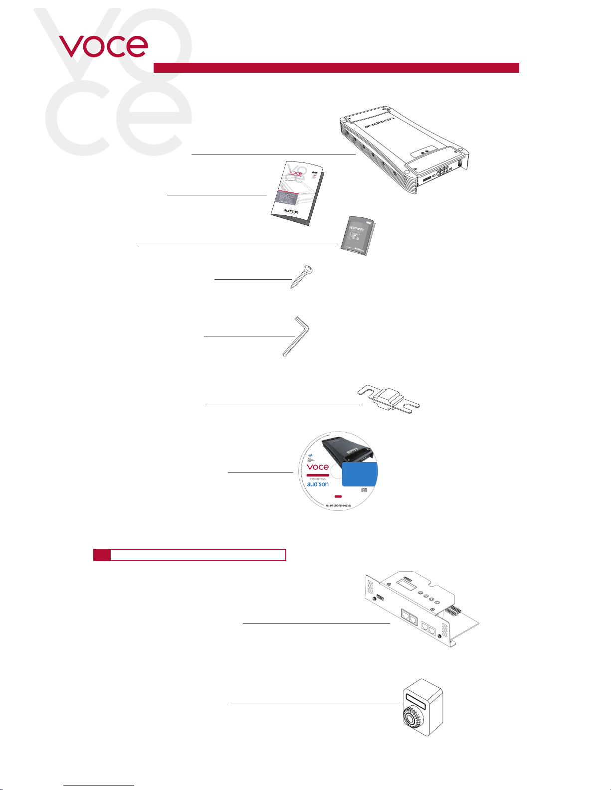
2. PACKAGING CONTENT
- Amplifier AV quattro
- Quick start guide
AV bit IN
AD Link
IN OUT
AC Link
IN OUT
MENU DOWN UP ENTER
AV bit IN
2.1 AVAILABLE ACCESSORIES (not provided)
- VCRA: SUB volume remote control
- AV bit IN: AV amplifiers digital interface
- CD ROM with:
This Owner’s manual (.pdf format)
Test tracks
- N. 1 Allen wrench 0,118”
- nr.4 3,9 x 25mm / 0,15” x 0,99
self-tapping cross-headed
fixing screws
TEST SIGNAL
Track_01. sine sweep (10 min)
Track_02. white noise (15 min)
Track_03. pink noise (10 min)
Track_04. sine wave 50 Hz - 0 dB (2 min)
Track_05. sine wave 1 kHz - 0 dB (2 min)
CD ROM
Owner’s Manuals
Manuali d’uso
AV Amplifiers
AV uno, AV due, AV quattro, AV 5.1k
Rev. 2.0
2
- nr.1 60A AFS spare fuse.
AV quattro
- Warranty

5
OWNER’S MANUAL
AV quattro /
AUDISON AMPLIFIERS CAN BE PART OF A HIGH POWER AUDIO SYSTEM THAT
CAN GENERATE VERY HIGH UNDISTORTED SOUND PRESSURE LEVELS.
PLEASE REMEMBER THAT LONG EXPOSURE TO AN EXCESSIVELY HIGH
SOUND PRESSURE LEVEL MAY DAMAGE YOUR HEARING; THEREFORE,
PLEASE USE COMMON SENSE AND PRACTICE SAFE SOUND.
Safety must be at the forefront while driving. The listening volume should never
obscure the noise coming from the outside of your vehicle; you should be able to hear the sounds generated by your
vehicle in order to promptly face any emergency situation.
To achieve the best possible performance from your new components, we recommend you follow the instructions
in this manual carefully. In order to design and create top level car hi-fi systems you need to understand automobile
mechanical and electrical issues very well; if you think you lack the required knowledge or the proper tools, please
consult with a specialized installer.
A professional installation will ensure your system delivers all the performance you have paid for, without affecting the
safety and reliability of your vehicle.
This manual has been designed to provide you with the basic instructions required to install and use this product.
However, the range of possible applications is very wide; to obtain further information, please contact your authorized
Audison dealer or Audison service center.
You can also send an e-mail directly to the following addresses:
Italy - supporto.tecnico@elettromedia.it
Worldwide - support@elettromedia.it
3. SAFE SOUND
3

6
OWNER’S MANUAL
AV quattro /
4. GENERAL PRECAUTIONS
• This symbol indicates that you have to pay attention to these instructions. Disregarding them might cause
accidental harms or damage your amplifier.
• Before installing the amplifier, make sure you carefully read and understand all instructions.
• The vehicle electric system must have 12V DC voltage with negative to ground. Make sure your car has it in order
to avoid any damages to your amplifier and to the vehicle.
• Pre-plan the configuration of your new amplifier and the best wiring routes to ease installation.
• Always wear protective eyewear when using tools that may generate splinters.
• During installation, keep the amplifier in its packing as long as possible; this will protect it from damages.
• Secure all auxiliary devices you built to install the components to the vehicle structure through brackets, screws, nuts and bolts;
this insures stability and safety while driving.
• The amplifier detachment while driving can damage the people in the vehicle and other cars. Secure the amplifier at best, paying
utmost attention if installation is inside the passenger’s compartment. Do not carry out any installation inside the engine
compartment.
• Before installing the amplifier, turn off the source and all other electronic devices in the audio system for preventing any damages.
• Make sure the location you chose for the components does not affect the correct functioning of the vehicle mechanic and electric
devices.
• Do not run the cables or install the amplifier next to electronic gearcases.
• Use extreme caution when cutting or drilling the car plate, checking there are no electrical wiring or structural element underneath.
• Before connecting the power cable to the amplifier, disconnect the negative lead ( - ) from the car battery.
• Make sure power cable is not short circuited during installation and connection.
• Power cable must have mechanically resistant and self-extinguishing insulation. Its section have a size corresponding with what is
suggested in this manual. Avoid to run it over or through sharp edges or close to moving mechanical devices. Make sure it is well
fixed all along its length. Block positive and negative cables just close to the amplifier respective power supply terminal blocks
through a clamping screw.
• Use rubber grommets to protect the wire if it runs in a hole of the plate or proper materials if it is close to heat-generating parts.
• To ground the device ( - ) in the right way, use a screw in the vehicle chassis; scrape all paint or grease from the metal if
necessary, checking with a tester that there is continuity between the battery negative terminal ( - ) and the fixing point. If
possible, connect all components to the same ground point; this solution rejects most noise.
• Route all signal cables away from power cables.
• Never run cables outside the vehicle; you would not be protected against wear and in case of accidents.
• When installing speakers and the cables that connect them, make sure that non-insulated parts never touch, even occasionally,
the vehicle cutting parts. If they do, the amplifier protection is activated.
• To prevent all problems, use very good quality cables, connectors and accessories, choosing them in Connection catalogue.
• When installation is over, and before plugging the main power supply fuse, check the system wiring and make sure all
connections were done in the right way.
• Power amplifiers put an increased load on the battery and on its charging system. We recommend checking your alternator and
battery condition to ensure they can handle the increased consumption. Standard electrical systems which are in good condition
should be able to stand this extra load without problems but we recommend the use of an energy storage capacitor and/or a
battery for high level audio systems.
• Put a fuse and its insulated fuse holder 40 cm max. far from the battery positive terminal; connect one end of the power cable to it
after connecting the other end to the amplifier. The fuse value must be 50% higher than the amplifier built-in one. In case the
cable supplies several amplifiers, the fuse value will have to be 50% higher than the sum of the values of all other fuses in the
amplifiers.
• There must be good air circulation where the amplifier is installed; this area must not be affected by humidity, rain, external
deposits or parts coming from the vehicle mechanical devices. Do not hinder in any way the cooling of the amplifier side fins
• Install the amplifier in the vehicle parts where temperature is between 0°C (32°F) and 55°C (131°F).
WARNING. When working in demanding conditions, the amplifier can reach temperatures of around 80 - 90°C
(176 ÷ 194°F). Make sure it is not dangerously hot before touching it.
• Periodically clean the amplifier without using aggressive solvents that might damage it. Dampen a piece of cloth with water
and soap, wring it and clean the amplifier. Then use a piece of cloth dampened with water only; eventually clean the amplifier
with a dry piece of cloth.
• Remove dust and solid deposits from the heat sink side fins. Don’t use compressed air on the amplifier since it would push
solid parts in the amplifiers. If necessary, please contact a specialised service centre for internal cleaning. Cooling system
obstruction makes the amplifier go in safety mode.
4
7
OWNER’S MANUAL
AV quattro /
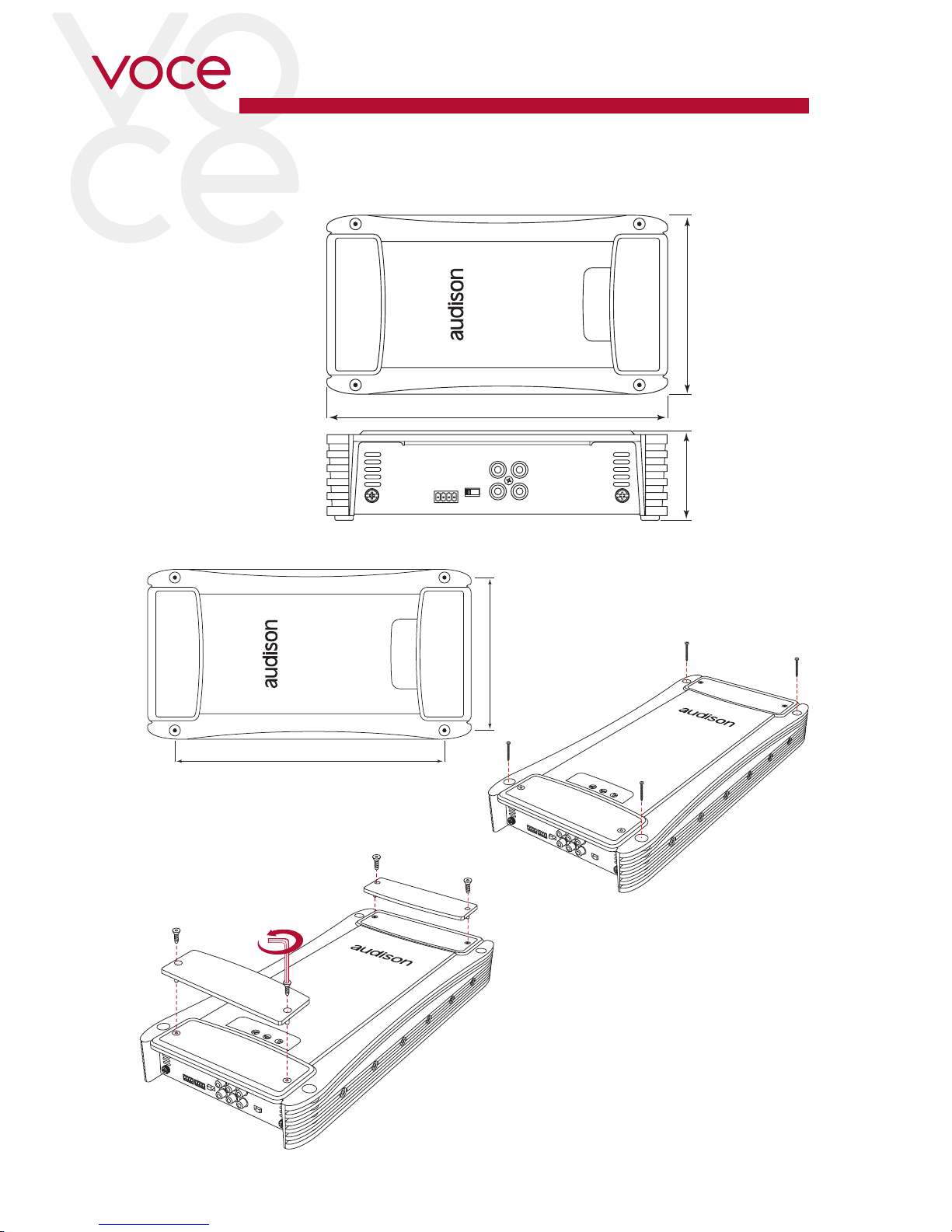
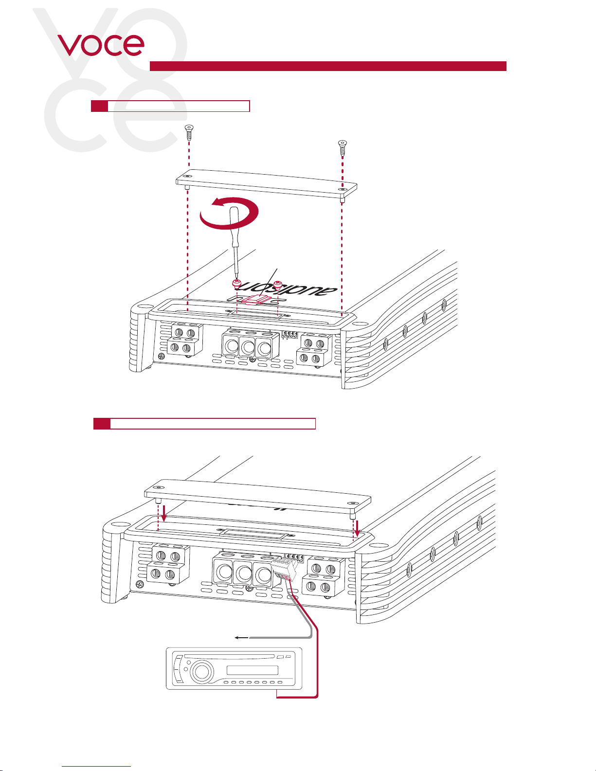
5. INSTALLATION
External size
How to remove the panel
Mounting size
How to mount
self-tapping screw 3,9 x 25 mm / 0,15” x 0,99
5
399 mm / 15,72”
198 mm / 7,8”
470 mm / 18,50”
220 mm / 8,66”
58 mm / 2,28”
Allen wrench
0,118”
8
OWNER’S MANUAL
AV quattro /
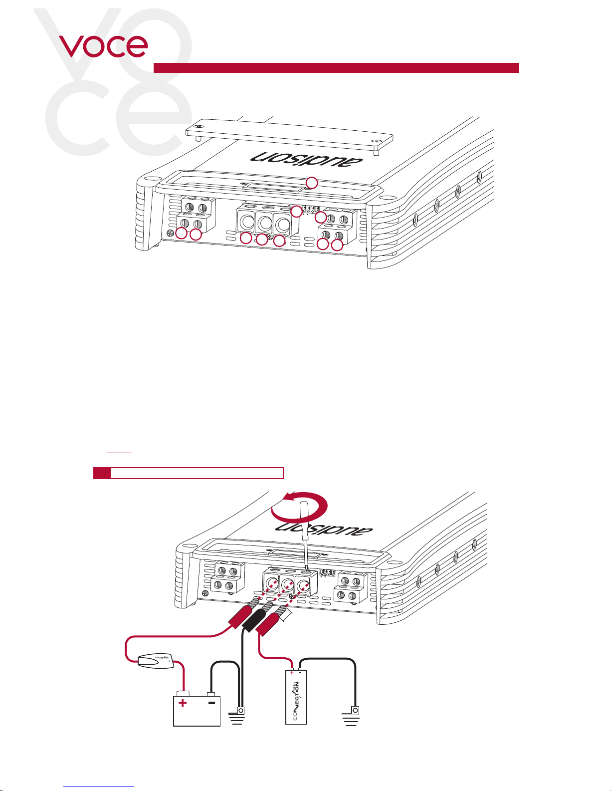
1. Protection fuse: 60 A;
2. Power (Ground): Terminal block for the amplifier power supply negative pole connection. Insert here the battery
negative cable or wire connected to the vehicle chassis. The plug accepts cables up to 2 A.W.G.
For better current transfer it is recommended to use cables with the maximum cross-section possible and in any
case of the same cross-section of the cable connected to the positive pole;
3. Power (11-15 VDC): Terminal block for the amplifier 11÷15V DC power supply positive pole connection.
Insert here the battery positive cable. The plug accepts cables up to 2 A.W.G. For better current transfer it is
recommended to use cables with the maximum cross-section possible and in any case of the same cross section of the cable connected to the negative pole;
4. +CAP: Terminal for connecting the positive pole of an external capacitor.
5. +/- Left A Speaker Out:
6. +/- Right A Speaker Out:
7. +/- Left B Speaker Out:
8. +/- Right B Speaker Out:
9. Remote Sub Control: inputs for remote control of the VCRA Sub volume control (optional).
10. Remote IN/OUT. REMOTE IN: terminal for the remote cable coming from the device which turns on the amplifier.
REMOTE OUT: terminal to launch the remote voltage to turn on other amplifier. The output voltage is 12V 50 mA.
On this terminal the start-up control will be available for other devices even if Rem In is not in use and SPKs IN
(see 7.2) are in use for starting-up.
6. REAR PANEL
6.1 HOW TO CONNECT POWER CABLES
AV quattro
AL AR
BL BR
BATT GND CAP
SUB VOL.
CONTROL
REMOTE
OUT IN
1
4
8
6
3
2
7
9
10
5
6
AV quattro
AL AR
BL BR
BATT GND CAP
SUB VOL.
CONTROL
REMOTE
OUT IN
L: min 16 mm (5/8”)
L: max 26 mm (1”)
Ø MAX: 2 AWG
Ground
Super
Capacitor
not provided
Fuse
Holder
not provided
GroundBattery
9
OWNER’S MANUAL
AV quattro /
6.2 HOW TO REPLACE THE FUSE
6.3 HOW TO CONNECT THE REMOTE SWITCH
6
AV quattro
AL AR
BL BR
BATT GND CAP
SUB VOL.
CONTROL
REMOTE
OUT IN
60A ASF Fuse
(provided)
AV quattro
AL AR
BL BR
BATT GND CAP
SUB VOL.
CONTROL
REMOTE
OUT IN
REMOTE OUT
to other amplifier
REMOTE OUT
10
OWNER’S MANUAL
AV quattro /
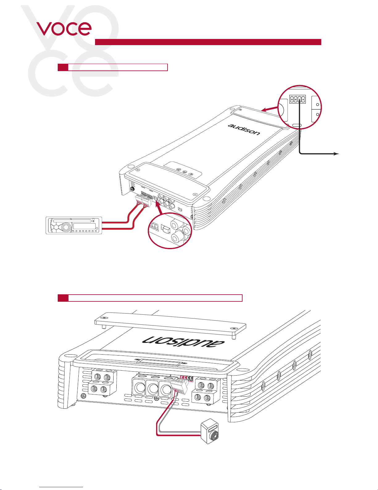
6.4 REMOTE SWITCHING VIA SPK IN
6.5 HOW TO CONNECT THE SUB REMOTE VOLUME CONTROL
REMOTE
OUT IN
SUB VOL.
CONTROL
AV quattro
AL AR
BL BR
BATT GND CAP
VCRA Sub remote control
(optional)
SPK IN
(1.2 - 20V)
L
- + - +
R
CH A
L
- + -
+
R
CH B
PRE
OUT
IN B
IN B
(IN A)
IN A
L
L
R
ON
OFF
OFF ON
R
A
RT
LEFT
RIGHT
REMOTE
OUT IN
SUB
VOL
BR
CAP
REMOTE OUT
to other amplifier
L
+ - +
R
IN A
L
R
ON
OFF
ART
6
11
OWNER’S MANUAL
AV quattro /
SPK IN
(1.2 - 20V)
AV quattro
L
- + - +
R
CH A
L
- + - +
R
CH B
ART
PREOUTIN B
IN B
(IN A)
IN A
LL
R
ON OFF OFFON
R
MONO INPUT
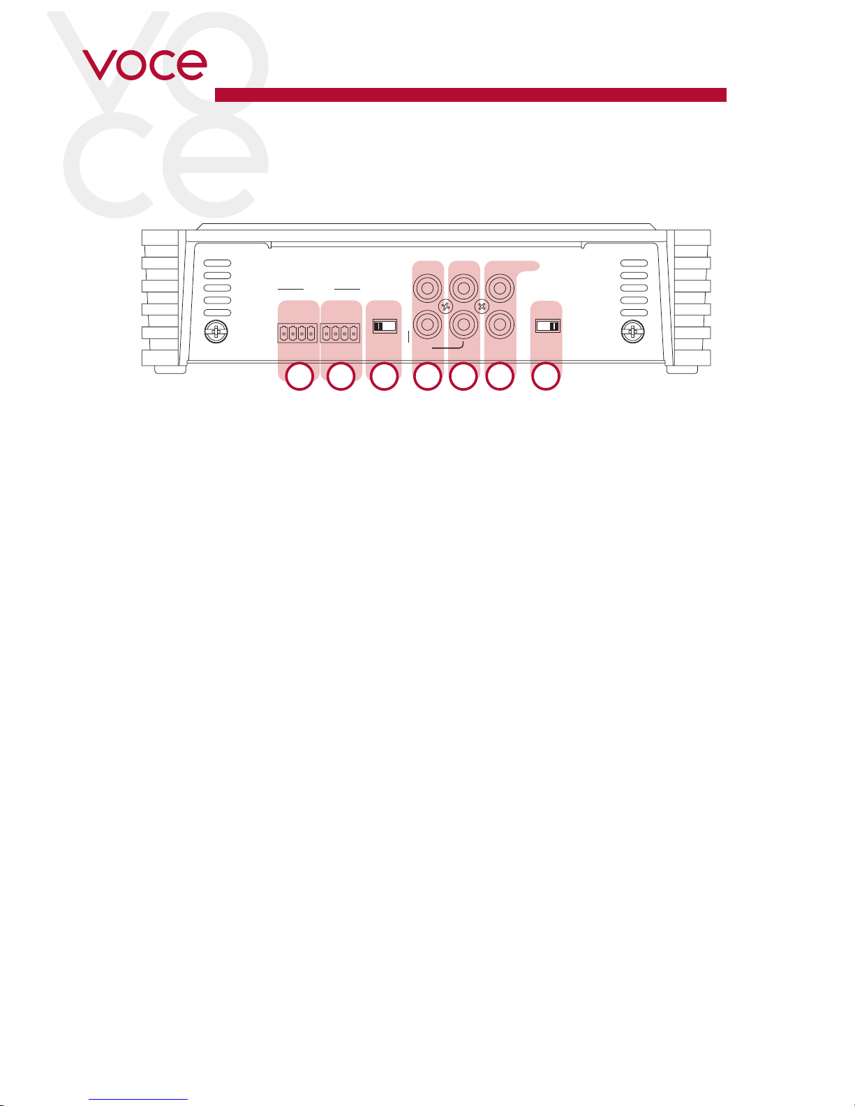
1. IN A: Channel A left and right analog inputs. Set the IN B switch to OFF, through this input you can drive channel
B left and right inputs.
2. IN B: Analog inputs for channel B left and right. Set the IN B switch to ON.
3. PREOUT: This jack provides A channel Left and Right preamplified outputs to drive a separate amplifier (typical
with subwoofer). These signals are full range, without crossover action.
4. SPK IN CH A: Channel A high-level left and right analog inputs.
5. SPK IN CH B: Channel B high-level left and right analog inputs.
6. ART (ON-OFF): If the source does not feature a 12V DC REMOTE OUT, set the ART switch to ON to turn on the
amplifier plugging the cables to the SPK IN signal inputs.
If the source features a 12V DC REMOTE OUT, set the ART switch to OFF.
7. IN B (ON-OFF): Select OFF to drive B channels with A input signals. Whit this setup, do not connect B inputs.
If the source features a REAR output, select ON and connect its signals to B inputs (B PRE-IN or B HI-IN).
7. FRONT PANEL
21654
3 7
7
 Loading...