

Page 1

PROFESSIONAL
SERIES
Remote Keyless Entry
Installation Guide
ca 2051
1ca2051 rev B. 2011 Audiovox Electronics Corporation. All right s reserved.
Page 2

Table of Contents
Before You Begin ......................................................................................3
Wire Connection Guide ........................................................................... 4
10 Pin Main Harness .................................................................................5
6 Pin Door Lock Harness.......................................................................... 8
Additional Ports ........................................................................................ 9
LED Port..................................................................................................... 9
Programming Port...................................................................................... 9
Set Up & Programming ..........................................................................10
Transmitter Programming........................................................................ 10
Manual Feature Programming.................................................................10
Programming Feature Banks .................................................................. 11
Chirp Delete - User Accessible .............................................................. 11
Feature Descriptions ............................................................................. 12
Transmitter Button Functions ............................................................. 13
System Layout .........................................................................................14
2 ca2051 rev B. 2011 Audiovox Electronics Corporation. All rights reserved.
Page 3
BEFORE YOU BEGIN
PROFESSIONAL INST ALLA TION
STRONGLY RECOMMENDED
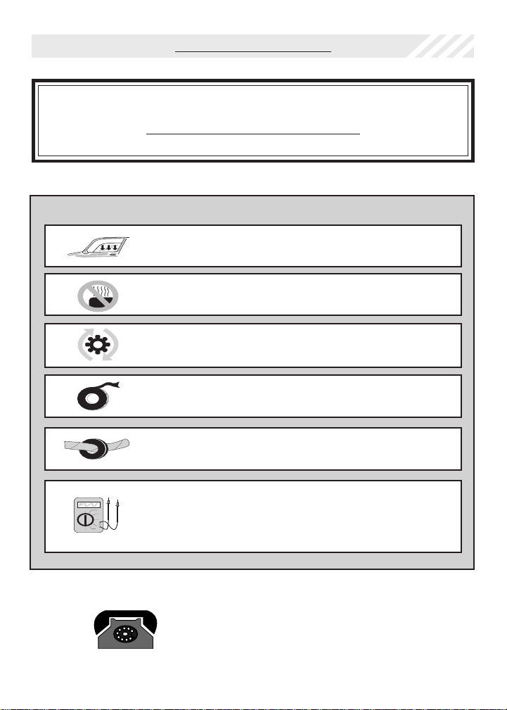
Installation Precautions:
Roll down window to avoid locking keys in vehicle
during installation
Avoid mounting components or routing wires near
hot surfaces
Avoid mounting components or routing wires near
moving parts
Tape or loom wires under hood for protection and
appearance
Use grommets when routing wires through metal
surfaces
Use a Digital Multi Meter for testing and verifying
circuits. DO NOT USE A TEST LIGHT, OR
"COMPUTER SAFE PROBE" as these can set off air
bags or damage vehicle computers.
Technical Support (800) 421-3209
or go to
http://techservices.codesystems.com
3ca2051 rev B. 2011 Audiovox Electronics Corporation. All right s reserved.
Page 4
10 Pin Main Harness
1
BLUE/GREEN 2ND UNLOCK OUTPUT ( - )
2
BLACK/WHITE ILLUMINATED ENTRY OUTPUT ( - )
3
WHITE/RED PARKING LIGHT INPUT
4
WHITE PARKING LIGHT OUTPUT
5
BLACK GROUND
6
ORANGE GROUND WHEN ARMED OUTPUT ( - )
7
RED BATTERY 12V ( + )
8
BROWN/BLACK HORN OUTPUT ( - )
9
YELLOW IGNITION INPUT ( + )
10
RED/WHITE TRUNK RELEASE OUTPUT ( - )
10 PIN MAIN
6 Pin Door Lock Harness
4 ca2051 rev B. 2011 Audiovox Electronics Corporation. All rights reserved.
Page 5

10 Pin Main Harness
1 BLUE/GREEN 2ND UNLOCK OUTPUT ( - )
This wire provides a ( - ) 200mA output upon the second press of unlock. This
output is used unlock the remaining passenger doors when the system is set up
for driver priority unlock.
2 BLAC K/WHITE ILLUMINATED ENTR Y OUTPUT ( - )
This wire provides a ( - ) 200mA output for 30 seconds when the system is
disarmed capable of driving relays.
Locate the vehicle’s dome light or pin switch wire.
Verification: This wire will register positive voltage or ground when the
vehicle's dome light is turned ON.
3 WHITE/RED PARKING LIGHT INPUT
4 WHITE PARKING LIGHT OUTPUT
Locate the parking light output wire at the vehicle’s light switch.
Verification: This wire registers positive voltage when the parking lights
are turned on.
Positive switching Parking Lights:
Connect the WHITE/RED wire to a 15 Amp max fused battery source.
Connect the WHITE wire to the parking light output wire.
Negative switching Parking Lights:
Connect the WHITE/RED wire to a good chassis ground.
Connect the WHITE wire to the parking light output wire.
5ca2051 rev B. 2011 Audiovox Electronics Corporation. All right s reserved.
Page 6

5 BLACK GROUND
Connect the BLACK wire to a solid chassis ground point using a ring terminal and
self tapping screw (not supplied). Scrape away paint from the grounding point to
ensure a good connection. The recommended grounding point is a metal surface
in the driver’s side kick panel area.
NOTE: Do not ground the BLACK wire with any other vehicle components.
6 ORANGE GROUND WHEN ARMED OUTPUT ( - )
This wire will have a continuous ( - ) 500mA output when the system is Armed. This
wire is typically used for controlling a starter interrupt relay, window modules or
additional sensors.
7 RED BATTERY 12V ( + )
Locate 1 of the vehicle’s constant 12 Volt battery wires at the ignition switch.
Verification: This wire will register ( + ) voltage in all positions of the ignition
switch.
Connect the RED wire to the constant 12 Volt battery wire.
NOTE: Remove all fuses until all connections are made.
8 BROW N/BLACK HORN OUTPUT ( - )
Locate the vehicle’s horn wire.
Verification: This wire will register at positive voltage and register
ground when the horn switch is pressed.
Connect the BROWN/BLACK wire to the vehicle’s horn wire. This is a low current
output, 200mA.
6 ca2051 rev B. 2011 Audiovox Electronics Corporation. All rights reserved.
Page 7

9 YELLOW IGNITION INPUT ( + )
Locate the vehicle’s ignition wire at the ignition switch.
Verification: This wire registers voltage when the key is turned to the ON (or
RUN) position. The voltage does not drop out when the key is turned to the
START (or CRANK) position.
Connect the YELLOW wire to the vehicle’s Ignition wire.
10 RED/WHITE TRUNK RELEASE OUTPUT ( - )
Locate the vehicle’s trunk release wire at the trunk release switch.
Verification: This wire will register either positive voltage or ground when the trunk
release is activated.
This is a low current output, 200mA.
7ca2051 rev B. 2011 Audiovox Electronics Corporation. All right s reserved.
Page 8

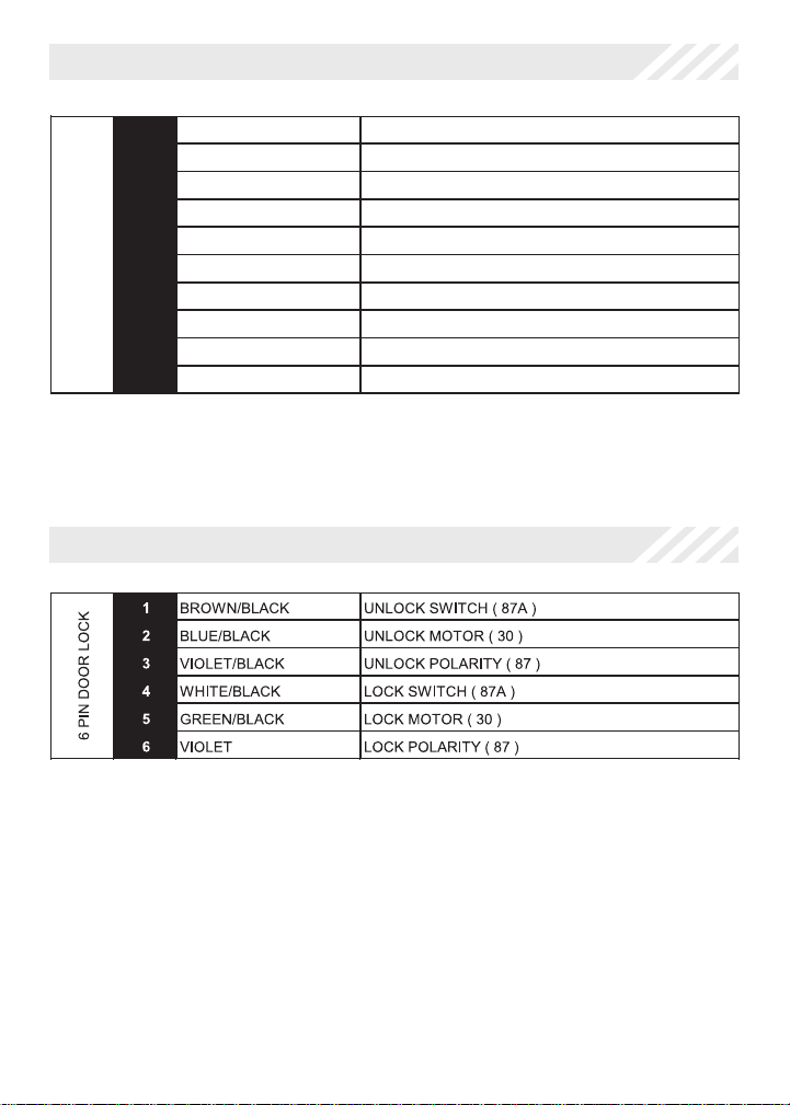
6 Pin Door Lock Output Harness
1 BROW N/BLAC K UNLOCK SWITCH ( 87A )
2 BLUE/BLACK UNLOCK MOTOR ( 30 )
3 VIOLET/BLACK UNLOCK POLARITY ( 87 )
4 W HI TE /B LA CK LOCK SWITCH ( 87A )
5 GREEN/BLACK LOCK MOTOR ( 30 )
6 VIOLET LOCK POLARITY ( 87 )
The door lock / unlock outputs are designed to control several different types of
systems which may require additional parts.
3 Wire Ground Switched Door Locks:
Connect the GREEN/BLACK wire to the wire that provides a ground signal from
the factory door lock switch to the factory door lock control relay.
Connect the BLUE/BLACK wire to the wire that provides a ground signal from the
factory door unlock switch to the factory door lock control relay.
Connect the VIOLET and the VIOLET/BLACK wires to a solid chassis ground
point. The WHITE/BLACK and BROWN/BLACK wires are not required for this type
of door lock/unlock system.
3 Wire Positive Switched Door Locks:
Connect the GREEN/BLACK wire to the wire that provides a +12 volt signal from
the factory door lock switch to the factory door lock control relay.
Connect the BLUE/BLACK wire to the wire that provides a +12 volt signal from
the factory door unlock switch to the factory door lock control relay.
Connect the VIOLET and the VIOLET/BLACK wires to a +12 volt battery source.
The WHITE/BLACK and BROWN/BLACK wires are not required for this type of
door lock/unlock system.
8 ca2051 rev B. 2011 Audiovox Electronics Corporation. All rights reserved.
Page 9

Additional Ports
LED Port
The LED included in the kit will serve as a visual indicator of the alarm’s status. It
should be installed in the dash, located where it can be easily seen from outside
the vehicle, yet not be distracting to the driver. Once a location has been
selected, check behind the panel for wire routing access, and to confirm the drill
will not damage any existing components as it passes through the panel. Drill a
1/4" hole, and pass the red and blue wires from the LED through the hole, from
the front of the panel. Firmly press the body of LED into the hole until fully seated.
Programming / Valet Button Port
Select a mounting location that is within reach of the ignition switch, as this
switch in combination with the ignition switch, will be used to program the certain
features of the system. It is suggested that the switch be mounted to the lower
dash panel in the driver’s area within reach of the driver.
9ca2051 rev B. 2011 Audiovox Electronics Corporation. All right s reserved.
Page 10

Set Up & Programming
Transmitter Programming - Feature Bank 1
1. Turn the ignition ON.
2. Press and hold the valet/override button.
3. Within 10 seconds the system will chirp (3) three times.
4. Press 1 button of each transmitter you wish to program.
5. The system will respond with 1 chirp for each accepted transmitter.
6. Pressing the override button at anytime during programming will advance to
the next bank.
NOTE: The system will exit transmitter programming after 15 seconds of inactivity.
NOTE: This system has 1 button programming which programs all channels of the
system.
NOTE: The system will hold up to 4 transmitters in memory, programming a 5th
transmitter will erase the oldest transmitter in memory.
Manual Feature Programming - Feature Bank 2 & 3
1. Turn the ignition ON.
2. Press and hold the valet/override button.
3. Within 10 seconds the system will chirp (3) three times.
4. Use the valet/override button to advance through each option bank. For
feature programming advance to Feature Bank 2 or 3, which is (4) four or
(5) five chirps.
5. Use the transmitter button to scroll through the selections in each
feature bank, the system will chirp to match the feature number.
6. Press the transmitter button to change the desired feature. The LED will
flash indicating the changed feature.
Defaulting All Features: Pressing the button anytime while in any of the
feature banks will default all features and return you to feature bank 2 - 4 chirps.
NOTE: The system will remain in feature programming mode as long as the
ignition is on, there is no time limit. T o exit programming turn the IGNITION OFF.
10 ca2051 rev B. 2011 Audiovox Electronics Corporation. All rights reserved.
Page 11

Feature Bank 1 -
3 Chirps
Transmitter Programming
Refer to transmitter programming.
Feature Bank 2 -
4 Chirps
Security Control
1 LED Flash 2 LED Flash 3 LED Flash 4 LED Flash 5 LED Flash
1 Silent Choice ON
OFF
Feature Bank 3 -
5 Chirps
Output Control
1 LED Flash 2 LED Flash 3 LED Flash 4 LED Flash 5 LED Flash
1
Extended Lock Pulse
1 Second
3.5 Seconds
1 Second Lock,
Double Pulse
Unlock
30 Second
Lock, Double
Pulse Unlock
Double Pulse
Lock, 1 Second
Unlock
2
2nd Unlock Output
2nd Unlock
Factroy Disarm
3
Ignition Controlled Locks
OFF
Lock and
Unlock
Lock Only Unlock Only
4
Trunk Output Timing
Red / White Output
Push and Hold
10 Seconds 20 Seconds
Latched until
IGN ON
Latched ON
until Button
Press
5
Horn Output Timing
16mS
10mS 30mS 40mS 50mS
Chirp Delete - User Accessible
System ARM/DISARM chirps can be toggled ON or OFF without entering the
programming feature banks.
1. Turn the ignition ON then OFF.
2. Press and release the valet/programming button 3 times. The system
will respond with 1 chirp for ON or 2 chirps for OFF.
11ca2051 rev B. 2011 Audiovox Electronics Corporation. All right s reserved.
Page 12

Feature Descriptions
Feature Bank 2 - Security
1 - Silent Choice: Controls the normal arm/disarm chirps of the security system.
ON - Silent arming/disarming upon first press of lock/unlock, pressing lock/
unlock a second time will activate the arm/disarm chirps respectively. The
system will only sound the arm/disarm chirps upon a second press of the
lock/unlock buttons.
OFF - normal arm/disarm chirps upon the first press of lock/unlock.
Feature Bank 3 - Output Control
1 - Extended Lock Pulse: Controls the timing of the BLUE and GREEN lock
output wires.
1 Second - Single 1 second lock pulse, single 1 second unlock pulse.
3.5 Seconds - Single 3.5 second lock pulse, single 3.5 second unlock pulse.
1 Second Lock, Double Pulse Unlock - Single 1 second lock pulse, double 1
second unlock pulse.
30 Second Lock, Double Pulse Unlock - Single 30 second lock pulse, double
1 second unlock pulse.
Double Pulse Lock, 1 Second Unlock - Double 1 second lock pulse, single 1
second unlock pulse.
2 - 2nd Unlock Output: Controls the timing of the BLUE/GREEN 2nd unlock
output.
2nd Unlock - Same output as unlock with 2nd press of unlock.
Factory Disarm - Single 1 second pulse with unlock and trunk release
activation.
3 - Ignition Controlled Locks: Control of door locks when the ignition is cycled
ON or OFF .
OFF - Door locks not activated by ignition.
Lock and Unlock - Doors lock when ignition is turned on and unlock when
ignition is turned off.
Lock Only - Doors lock when ignition is turned on.
Unlock Only - Doors unlock when ignition is turned off
12 ca2051 rev B. 2011 Audiovox Electronics Corporation. All rights reserved.
Page 13

4 - Trunk Output Timing - Red/White Output: Control of the RED/WHITE trunk
release output wire when trunk release is activated from the transmitter.
Push and Hold - Output is continuously active until transmitter button is
released.
10 Seconds - Output stays active for 10 seconds regardless of length
button press on transmitter.
20 Seconds - Output stays active for 20 seconds regardless of length
button press on transmitter.
Latched until IGN ON - Output stays active until the ignition is turned on.
Latched ON until Button Press - Output stays active until deacvtivated by
transmitter.
5 - Horn Output Timing: Control the minimum horn pulse time in milli seconds,
some vehicle will require a longer pulse to activate the factory horn.
16mS 10mS 30mS 40mS 50mS
Transmitter Button Functions
13ca2051 rev B. 2011 Audiovox Electronics Corporation. All right s reserved.
Page 14

BROWN/BLACK UNLOCK SWITCH ( 87A )
BLUE/BLACK UNLOCK MOTOR ( 30 )
VIOLET/BLACK UNLOCK POLARITY ( 87 )
WHITE/BLACK LOCK SWITCH ( 87A )
GREEN/BLACK LOCK MOTOR ( 30 )
BLUE/GREEN 2ND UNLOCK OUTPUT ( - )
BLACK/WHITE ILLUMINATED ENTRY OUTPUT ( - )
WHITE/RED PARKING LIGHT INPUT
WHITE PARKING LIGHT OUTPUT
BLACK GROUND
ORANGE ARMED OUTPUT ( - )
RED BATTERY 12V ( + )
BROWN/BLACK HORN OUTPUT ( - )
YELLOW IGNITION INPUT ( + )
LED PORT
PROGRAMMING / VALET PORT
RED/WHITE TRUNK RELEASE OUTPUT ( - )
VIOLET LOCK POLARITY ( 87 )
CA 2051
14 ca2051 rev B. 2011 Audiovox Electronics Corporation. All rights reserved.
Page 15

15ca2051 rev B. 2011 Audiovox Electronics Corporation. All right s reserved.
Page 16

Audiovox Electronics Corporation.
Customer Service 1-800-421-3209
WWW.CODE-ALARM.COM
FCC COMPLIANCE
This device complies with Part 15 of the FCC rules and with RSS-210 of
Industry Canada. Operation is subject to the following two conditions:
1. This device may not cause harmful interference, and
2. This device must accept any interference received, including any interference
that may cause undesired operation.
Warning!
Changes or modifications not expressly approved by the party responsible for
compliance could void the user’s authority to operate the equipment.
16 ca2051 rev B. 2011 Audiovox Electronics Corporation. All rights reserved.
 Loading...