

Page 1
SRS1000 Theater Sound Owner's ManualSRS1000 Theater Sound Owner's Manual
R
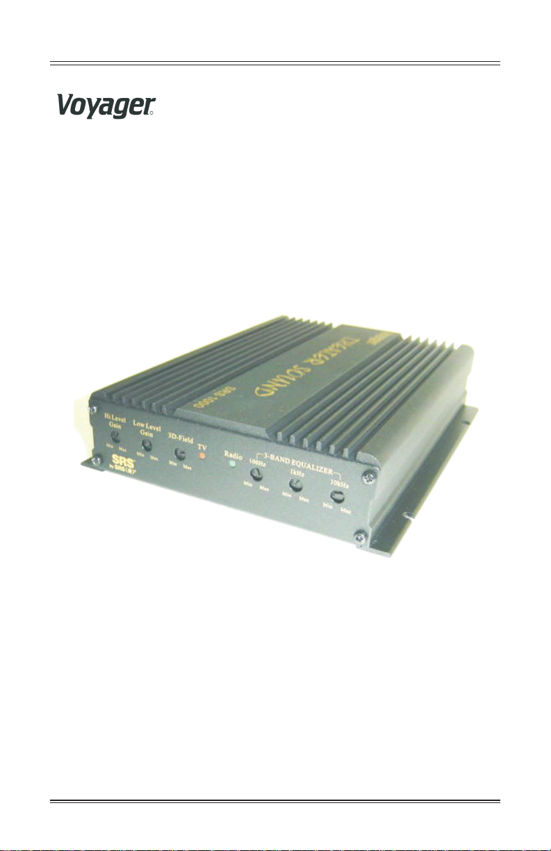
THEATER SOUND THEATER SOUND
SRS 1000SRS1000
Owner's ManualOwner's Manual
Page 2

SRS1000 Theater Sound Owner's ManualSRS1000 Theater Sound Owner's Manual
Congratulations!!!
You have purchased one of the best, integrated Radio/TV
amplification systems available for in-vehicle use today.
* Integrates TV and Radio sound into a single system for simplicity,
enhanced performance and ease of use.
* On-board EQ and SRS functions greatly enhance sound quality from TV
system.
* System can be added to an existing Radio system, or installed as a new
system with optional cube speakers (model SP250) and subwoofers
(model SP690).
* Sound quality parameters can be adjusted for optimum matching to
vehicle interior.
Features:
* 4 x 15W main speaker outputs; 2 x 25W subwoofer outputs.
* SRS processor by SRS Labs, Inc. Unlike simple stereo systems, which
produce a flat, 2 dimensional sound field, the SRS processor recovers lost
spatial (directional) cues to reproduce a 3 dimensional sound field. This 3
dimensional sound field is more true to listening to a live performance
than a traditional playback of a stereo recording. This feature is active for
TV mode only.
* TV/Radio mode is activated via a simple 12VDC trigger line, which can
be controlled by your own switch (integrated into your dash design, for
example).
* 3 band EQ (100Hz, 1KHz, 10KHz centers), +/_ 10dB boost/cut for each
band.
* TV and Radio gain controls to match the system to your devices for
optimum performance.
* 3D field adjustment, to match size of sound field to vehicle.
* Low level and high level inputs for radio and TV for convenience.
* Mode indicator LED's on front panel.
* Sleep mode (ultra-low current draw mode) after 2 minutes with no signal
detected.
* All controls factory preset with recessed knobs. This allows for easy
adjustment, yet controls cannot be accidentally adjusted while being
handled during installation.
* Extruded Aluminum heat sink housing.
* All connections made on rear panel, all adjustments made on front panel.
----- 1 -----
Page 3

SRS1000 Theater Sound Owner's ManualSRS1000 Theater Sound Owner's Manual
Front Panel Controls:
* Radio Gain adjustment
* TV Gain adjustment
* 3D Field adjustment
* Radio Mode LED indicator
* TV Mode LED indicator
* 100Hz adjustment
* 1KHz adjustment
* 10KHz adjustment
Rear Panel Connections:
* Main connector (Molex 16 pin, locking type). Handles power, speakers,
subwoofers, and TV mode trigger I/O's.
* Radio low level input (RCA L/R)
* TV low level input (RCA L/R)
* TV high level input (3.5mm mono jack)
* Radio high level input (8 pin Molex, locking type) for Radio speaker
feed direct
----- 2 -----
Page 4
SRS1000 Theater Sound Owner's ManualSRS1000 Theater Sound Owner's Manual
Provides a Three-Dimensional Image from a
Standard Stereo Source!
Benefits:
Natural 3D sound image from any two speaker stereo system
Based on characteristics of the human hearing system for natural, non
fatiguing sound
Supports mono, stereo, and surround sound for enjoyment with any
input material.
Fully immersive sound without a discernible sweet spot, allowing
superb sound from any listening position.
60 U. S. And foreign patents issued.
About the Technology:
SRS , the Sound Retrieval System , came about after many years of
research on the psychoacoustic of sound and the dynamics of the human
hearing system. SRS retrieves the spatial information from recordings
and restores the original three-dimensional sound field. As a result, the
reproduced sound is much closer to a live performance. Like live
performances, SRS has no critical listening position (sweet spot).
Listeners can move around the room and continue to be immersed in full
three-dimensional sound.
How the Technology Works:
A microphone does not possess the ability to inter pret the direction a
sound is coming from in the same way that the human ear does. However,
when the audio source is recorded, directional audio cues are still present
in the recording. Without the proper processing of the ambient
information, traditional stereo reproduces a flat, two-dimensional sound
field.
By breaking down the stereo signal into its various signal components,
it is possible to isolate and restore these spatial cues and place them in the
proper space relative to the direct sounds, such as a soloist or dialogue.
These spatial cues are restored by the use of Head Related Transfer
Functions (HRTFs) , which process ambient sounds via patented
frequency response correction curves.
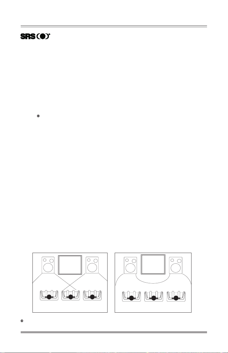
Stereo has a narrow sweet spot
1998 SRS Labs, inc. All Rights Reserved. SRS, the SRS logo, Sound Retrieval System are registered trademarks of SRS Labs, Inc.
All other corporate and brand names are trademarks of their respective holders.
SRS 3D Sound expand the stereo sweet spot
----- 3 -----
Page 5

SRS1000 Theater Sound Owner's ManualSRS1000 Theater Sound Owner's Manual
< Index >
1. Package Contents...........................................p1
2. Front/Rear Panel Description .........................p2
3. System Connections.......................................p4
4. Operation......................................................p5
5. Specification.................................................p7
Page 6

SRS1000 Theater Sound Owner's ManualSRS1000 Theater Sound Owner's Manual
Package Contents
1. SRS1000 Amplifier..................................1pc
r
r
e
e
R
g
g
a
d
i
a
a
o
G
a
y
y
i
n
o
o
TV
V
V
M
G
i
n
a
i
n
M
a
x
3
D-
M
F
i
n
i
e
l
d
M
a
x
T
V
M
i
n
M
a
R
x
a
d
i
o
3
1
0
B
0H
A
z
N
D
E
Q
M
i
1
n
k
M
a
x
M
i
n
2. Wire Harness - 16 pin - Main Connection ...1pc
Wire Harness - 8 pin - Radio High Level
3.
0
0
0
0
10
10
S
S
R
R
S
S
D
D
N
N
U
U
O
O
S
S
R
R
TE
TE
A
A
E
E
TH
TH
U
A
L
H
I
z
Z
E
R
1
0k
H
M
z
a
x
M
i
n
M
a
x
(Speaker Input )
..............................1pc
4. Owner's manual...........................1pc
----- 1 -----
SRS1000 Theater Sound Owner's ManualSRS1000 Theater Sound Owner's Manual
R
THEATER SOUND THEATER SOUND
SRS1000SRS1000
Owner's ManualOwner's Manual
Page 7
SRS1000 Theater Sound Owner's ManualSRS1000 Theater Sound Owner's Manual
Front/Rear Panel Description (1)
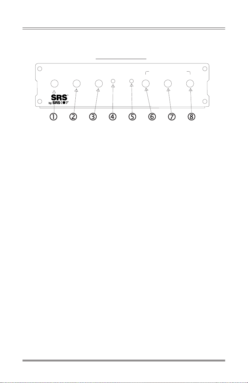
Front panel view
Radio
Gain
TV
Gain
Min
MaxMin
3D-Field
TV
Radio
3-BAND EQUALIZER
100Hz 1kHz
10kHz
MinMaxMax Min Min Max MaxMin Max
Front panel description:
1. Radio gain control---Adjust gain to match Radio signal level.
2. TV gain control---Adjust gain to match TV signal level
3. 3D field---Adjust depth of 3D effect
4. TV indicator ---Illuminated Orange LED when unit is in TV
mode.
5. Radio indicator---Illuminated Green LED will unit is in Radio
mode.
6. 100 Hz Band Adjustment---Adjust low frequency response
(Bass) of the amplifier when in TV mode .This control has no
effect on radio mode.
7. 1 kHz Band Adjustment---Adjust middle frequency response
(Midrange) of the amplifier when in TV mode .This control has no
effect on radio mode.
8. 10 kHz Band Adjustment---Adjust high frequency response
(Treble) of the amplifier when in TV mode .This control has no
effect on radio mode.
----- 2 -----
Page 8

SRS1000 Theater Sound Owner's ManualSRS1000 Theater Sound Owner's Manual
Front/Rear Panel Description (2)
Rear panel view
LRRR RF LF
+
__
Hi Level In
TV In
Hi Level
Line In
L R L
is a trademark of SRS Labs, Inc.
SW1 RFRR
R
SW2
Speaker Out
RadioTV
Trigger
LR LF DC
Made in China
+
_
Rear panel description:
1. Radio, high level speaker input. Using the included 8 pin wire
harness, connect the speaker output of the radio to SRS1000.
Follow connection diagram on page 4. Do not use this input
simultaneously with Radio Line In.
2. TV In, High Level -- This input is to be used only with monaural
TV's (non-stereo) that do not have variable, stereo, line level out
put. If this input is used, no connection should be made to Line In,
TV. Doing so would cancel the SRS 3D effect.
3.Line in, TV--Connect to Stereo TV variable line level out put .
Do not connect any cable to the TV In ,Hi Level Jack if this input is
used .
4.Line in ,Radio--Connect to variable line output from radio (if
available). Do not connect the 8 pin harness to the SRS1000 if this
input is used.
5.Main Connection Input. Use included 16 pin wire harness to
apply power, TV mode trigger, and all speaker outputs though this
connection. Refer to page 4 for details.
----- 3 -----
Page 9

SRS1000 Theater Sound Owner's ManualSRS1000 Theater Sound Owner's Manual
System Connections (2)
Note:
Be sure that left & right speaker
channels are connected properly from
TV, Radio, and to speakers. Care should
be taken to ensure proper polarity (+ to +
and - to -).
TV In
LRRR RF LF
+
__
Hi Level In
Hi Level
Note:
TV In, High Level -- This input
is to be used only with monaural
TV's (non-stereo) that do not
have vaiable, stereo, line level
out put. If this input is used, no
connection should be made to
Line In, TV. Doing so would
cancel the SRS 3D effect.
Line In
L R L
SUBWOOFER1
SUBWOOFER2
RadioTV
+
-
Tan/White
+
-
Brown/White
R
Tan
Brown
Car Radio/Tape
SW1 RFRR
SW2
LR LF DC
Speaker Out
Made in China
Note:
Connect Low Level input or
High Level input for each
device (Radio/TV), not both.
The unused input for device
should have no connection.
Trigger
Note:
+12 VDC = TV
Trigger
mode, 0 VDC =
Radio mode,
+
Trigger source
_
(switch etc) to be
provided by the
installer.
Yellow
Black
+
-
Blue
Trigger switch
Fuse 8.0A/250V
Car Battery
Car Battery
DC +12V
TV
+
RF
RR LR
-
Gray/Black
+
-
Gray
Voilet
White/Black
Green
Green/BlackVoilet/Black
White
+
-
LF
+
-
Note:
Connect Low Level input or High Level input
for each device (Radio/TV), not both. The unused
input for device should have no connection.
----- 4 -----
Page 10

SRS1000 Theater Sound Owner's ManualSRS1000 Theater Sound Owner's Manual
Operation
Connecting the speakers
1. Speaker impedance
a) Front & rear speakers : 4 minimum
b) Subwoofer1 & Subwoofer 2 speaker: 4 minimum
2. Be sure to connect the cords between the speaker terminal and
speaker systems with the same polarities(''+'' to ''+'' ,''-'' to ''-'' ), if not,
the central sound will be weak and the effect of the different
instruments will not be clear. It will diminish the stereo effect.
3. When connecting the speakers, be sure that the wires do not stick
out from the terminals and touch other terminal or the rear panel!
4. Checking connections.
a) Be sure all connections are made correctly before applying
power to the main unit. Damage to the unit may result if not connected
properly. Refer to page 4 for connection details.
b) Check the polarity (positive and negative ) of connections and
the directivity of stereo separation (right cord to right channel
terminal)
First Time Operation
Important: Before Applying Power:
a) Set all controls on SRS1000 to mid position (slot in knob will be
vertical).
b) Be sure TV mode trigger is not active (ie: 0 VDC)
c) Be sure that TV and Radio are off
System Set-Up (Gain Matching, EQ setting, 3D Effect setting)
1) Apply power to SRS1000. Verify Radio mode by checking
Radio/TV indicators on Front Panel.
2) Turn on Radio and select a program source (a strong radio station,
CD-play, etc). Adjust radio volume to approximately 1/4 volume.
3) Adjust Radio gain control up and down until suitable level is
reached. Check level setting by exercising radio volume control from
min to max and verifying overall volume levels at the speakers.
Note: EQ and 3D effect controls are only for TV mode operation.
When in Radio mode, these controls are bypassed.
4) Now apply power to the TV mode trigger, and verify TV mode is
active by checking indicator on the Front panel.
5) Turn on the TV , and select a program source (Strong station,
VCP/DVD playing , etc).
6) Adjust TV volume to approximately 1/4 volume , and adjust TV
gain control on SRS1000 until suitable level is obtained.
----- 5 -----
Page 11

SRS1000 Theater Sound Owner's ManualSRS1000 Theater Sound Owner's Manual
7) Adjust EQ until desired sound quality is reached. This is done
by turning each of the 3 knobs under "3 Band Equalizer" on the
front panel. 100Hz is for Bass, 1 Khz is for midrange, and 10 Khz is
for Treble.
8) Adjust 3D Effect knob to match size of vehicle. This control is
to compensate for the acoustic properties of small and large
vehicles, which are very different. As a gengeral rule of thumb, the
smaller the vehicle, the more 3D effect is needed to simulate the
full "theater experience". For the most part, however, this
adjustment is mostly according to personal taste.
----- 6 -----
Page 12

SRS1000 Theater Sound Owner's ManualSRS1000 Theater Sound Owner's Manual
Specifications:
1. Power Output (max. rating) :
Front channel : 15w+15w (4 )
Rear channel : 15w+15w (4 )
Subwoofer channel : 25w+25w (4 )
2. THD:
Front channel : 0.3%
Rear channel : 0.3%
Subwoofer channel : 0.5%
3. S/N ration : 75dB
4. TV Equalizer:
at 100Hz : 10 dB
at 1kHz : 10 dB
at 10k Hz : 10 dB
5. Auto mute at no signal : 2 minutes
6. Dimensions: 160(w) x 42(h) x 200(d) mm
7. Voltage range: 10.5V~16V
8. TV mode trigger voltage range: 10.5V~16V
9. Stereo separation: 50dB
10. SRS 3D field effect specifications: at 100Hz : + 7 dB
at 10kHz : + 5 dB
11. Current Draw:
Max : 6.5 A
Normal (1W output): 1.5 A
Min (no output-standby mode < 2 minutes no signal) :
0.6A
Sleep (> 2 minutes no signal): 90mA (TV) /45mA (Radio)
12. Frequency Response:
Front/Rear channels: 20Hz ~ 25kHz
Subwoofer channels: 20Hz ~ 500Hz
13. Signal Input Voltage Range:
Radio:
High: 2 V
Low : 200mV
TV :
High: 2 V
Low : 200mA
14. Gain Adjustment Range: 0 ~ 32 d B
Audiovox Specialized Applications. LLC WWW.ASAELECTRONICS.COM
----- 7 -----
 Loading...