

Page 1
Installation Guide
For the
Roof Mount Satellite Antenna for
SIRIUS/AVX Based Receiver Unit
MODEL SRANT-RMSIR
Page 2

1
Contents
1 Introduction......................................................................................................................................2
2 Roof-mount Antenna .......................................................................................................................2
3 General Instructions .........................................................................................................................3
4 Sedans ..............................................................................................................................................4
5 Convertibles.....................................................................................................................................7
6 SUV’s, Minivans and 5 Door Vehicles ...........................................................................................8
7 Pickup Trucks ..................................................................................................................................9
Page 3
2
1 Introduction
Your new Sirius satellite antenna, approved by
Sirius Satellite Radio, Inc., has been specially
designed to receive signals from Sirius’ three
satellites and Sirius’ network of ground-based
“repeater” transmitters.
Mechanical data:
Shape “Beveled teardrop”
Color Black
Dimensions 95mm x 70mm x 38mm (approx)
Weight 150 grams (5.25oz) (excl. cables)
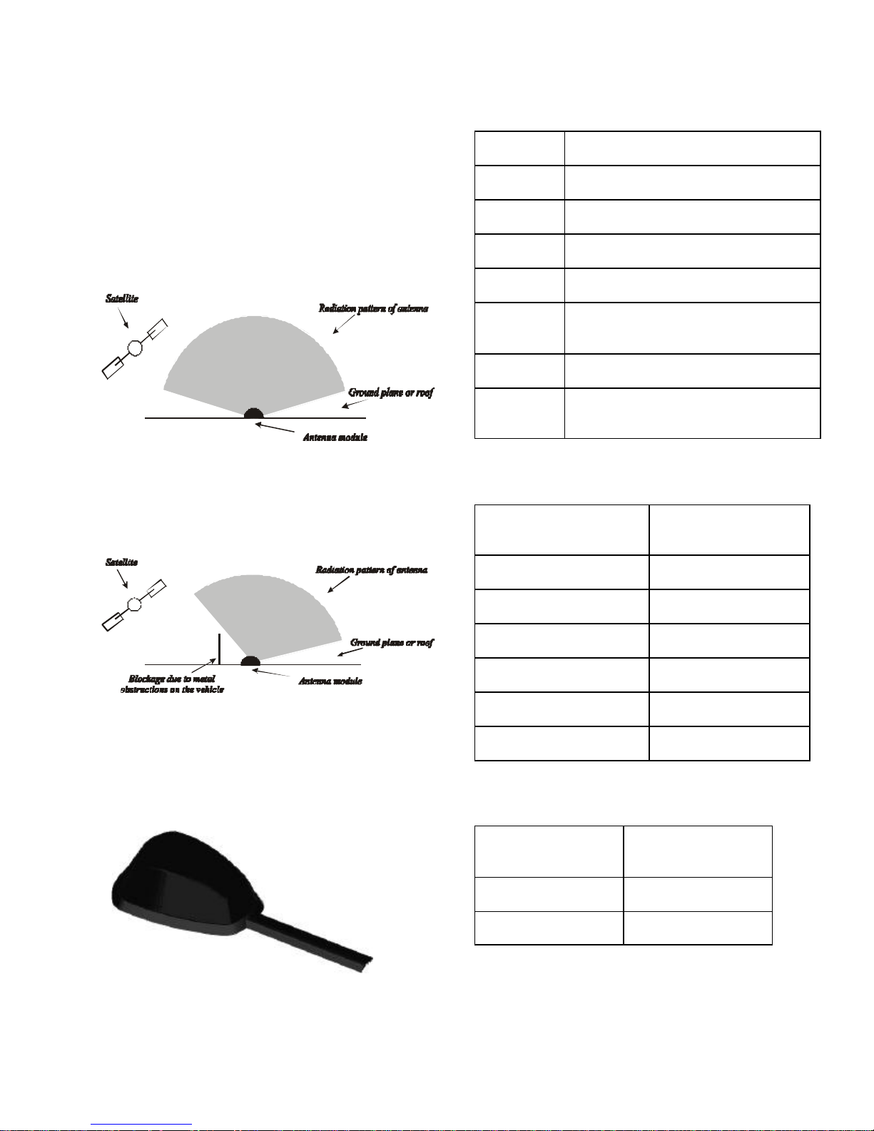
Figure 1: Ideal reception pattern
Figure 2: Effect of obstruction on reception pattern
Cables 4 meters (13 feet) micro low loss
Connectors 2 x FAKRA / SMB (keyed per specifi-
cation)
Mounting Acrylic foam adhesive pads
Cover Impact resistant glass filled nylon
(paintable)
Electrical data:
Sirius Per specification Sirius
RX000002-010300
Peak Gain (SAT) 6 dBic
3 dB beam width (SAT) 130 degree
4 dB beam width (SAT) 140 degree
Noise figure (SAT) 0.7 dB
Peak Gain (Ter.) 6 dBi
Noise figure (Ter.) 1.1 dB
2 Roof-Mount Antenna
Figure 3: Low Profile Roof -mount Sirius Antenna
Environmental data:
Functional operating
temperature
Storage temperature -45 to +120 degC
Humidity Power wash proof
-40 to +105 degC
Page 4
3
3 General Instructions
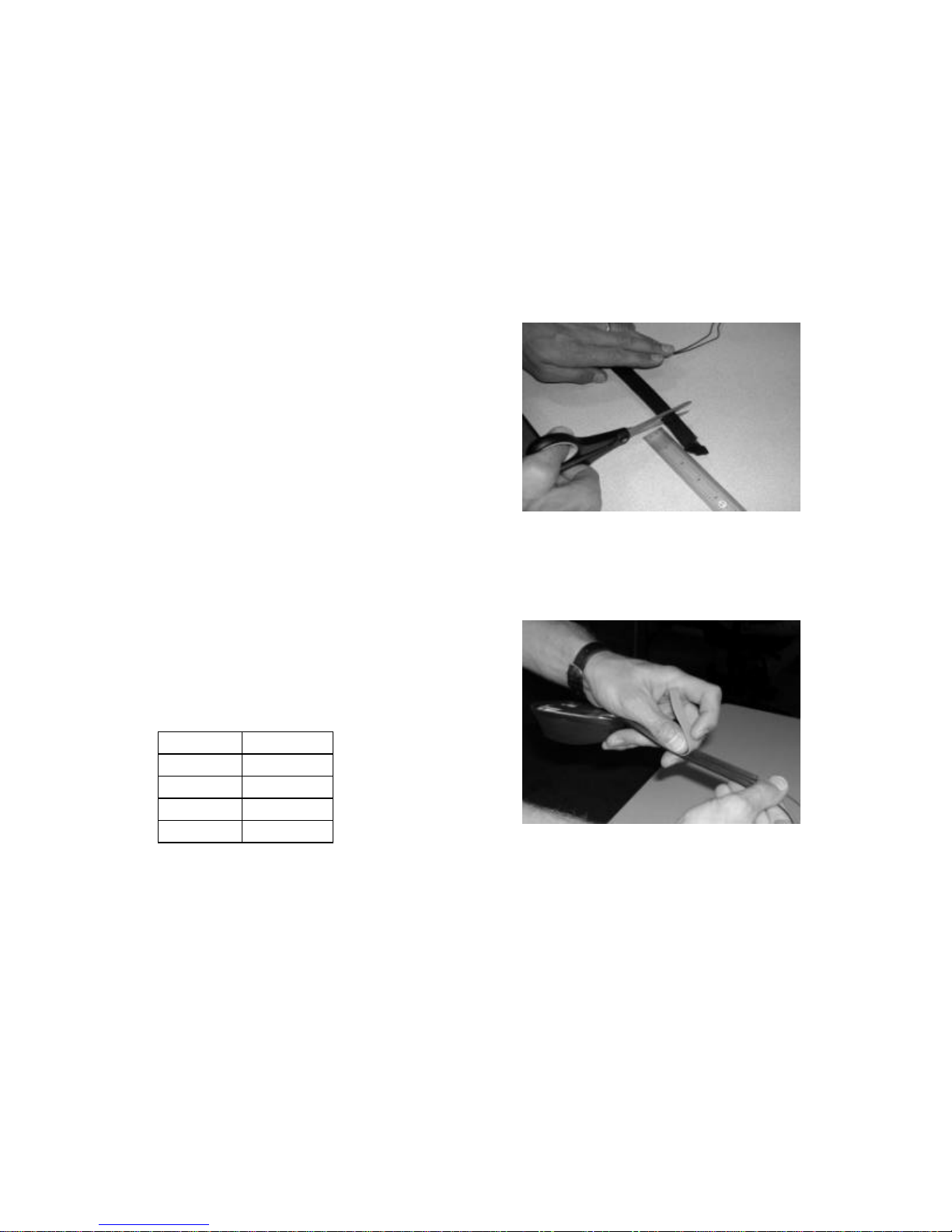
3.3 Shortening the antenna “tail”
Satellite antennas are extremely sensitive and
finely specified to facilitate reception of satellite signals under a variety of conditions across
the whole of North America. It is im portant to
read these “Instructions” carefully to ensure
that the antenna is mounted properly in the best
location in order to provide optimum reception
quality.
3.1 Mounting location
The satellite antenna should be mounted horizontally on a metal surface measuring at least
18 inches by 18 inches. The best reception
qual ity is achieved at the highest point of the
vehicle (i.e. the roof) but the trunk lid is an alternative location for convertibles and for some
sedans.
It is important that the antenna has a clear
“view” to the satellites and ground-based repeaters and should therefore be mounted in an
unobstru cted location (i.e. clear of roof racks,
sunroofs, other antennas). Use the table below
as a guide for the required distance (A) between
the antenna placement and a possible obstruction with a height of (B).
The antenna module is supplied with a 6 inch
tail. For vehicles with flat roofs (SUV’s, Minivans) and for convertibles, it is possible to
shorten the tail by up to 2 inches.
For vehicles with a sloping roof, or if the
module is mounted on the trunk of a sedan,
the tail should not be shortened!
Figure 4: Shortening the antenna tail
As soon as the precise length of the tail has
been determined, the adhesive strip may be cut
to length and applied to the antenna tail.
A B
12” 4”
18” 6”
24” 8”
30” 10”
(Glass sunroofs, which open outwards and
cover the rear roof area, should not affect the
location of the antenna module).
3.2 Installation temperature
Installation should be carried out when conditions are at room temperature or above. Firstly,
colder temperatures could affect the curing time
of the antenna module’s adhesive. Secondly,
when mounting the antenna module on a sedan,
it will be easier to work with the rubber molding around the window.
Figure 5: Applying adhesive tape
3.4 Removing the antenna
The antenna module may be removed, using a
nylon cord (e.g. fishing line) to cut through the
adhesive pad between the antenna module and
the vehicle. Work from the front to the tail in a
side to side cutting motion. Any remaining adhesive may be removed with an appropriate
cleaner.
Page 5

4
Figure 6: Removing antenna
4 Sedans
Figure 7: Installed antenna
The antenna module should be located along
the centerline of the roof, at least 4 inches from
the rear window.
The antenna cables should be tucked and routed
underneath the rubber molding around the rear
wi ndow and into the trunk
Fig. 8: Applying the antenna
5. Carefully tuck the cables under the rubber
molding, working from the tail of the antenna,
around the window and into the trunk area.
(A flat tip dental pick or cotter-pin remover is
ideal for lifting the rubber molding and tucking
in the cables.).
Note: Determine whether there is enough space
under the molding to conceal both cables, in
which case they may be run together. If not,
route a single cable around each side of the
window. (If there is no space available, it is
possible to mount the antenna module on the
trunk. Refer to “Converti bles”).
1. Clean the general area where the antenna is
to be mounted (using alcohol wipe provided).
2. Identify and mark the precise location of the
antenna module.
3. Peel off protective liner from adhesive pads.
4. Starting with the tail in position, work towards the module while applying pressure of
approximately 12 psi for a minimum of 15 seconds.
Note: Maximum adhesion occurs within 72
hours, during which time car washes and other
contact with the antenna should be avoided.
Figure 9: Cables routed together
Figure 10: Cables routed separately
Page 6

5
There are two types of window moldings, used
It
is important that the coaxial cable is
lation procedure. Routing the cable in the
window molding will not affect the sea
on most vehicles. Both are suitable for concealing the antenna cable.
Figure 13: Cables routed in standard molding
Figure 11: Outside rubber molding (most common)
Figure 12: Encapsulated molding (less common)
Note: The window molding will be more flexi-
ble and easier to work with at room tem perature
or above. Ensure the molding is clean, and if
necessary apply a small amount of oil to make
the process easier.
not damaged or kinked during the instal-
Figure 14: Lifting up difficult molding for routing each
cable in both directions
6. Route the cable from the lowest point of the
rear window into the trunk area. Take advantage of any existing cable channel or wiring
conduit.
ing of the window.
l-
Figure 15: Entering the trunk through cable channel
Page 7

6
Figure 18: Removing connector housings
Figure 16: Cables routed directly through the molding
and through the cable channel to the interior
7. If there is no suitable cable channel, the cable may be routed directly from the window
molding to the right or left corner of the trunk.
Figure 17: Cable routing along the trunk rubber molding
It may be necessary to remove the plastic housings from the antenna connectors in order to
feed the cables through narrow openings.
Most Sirius receivers have two antenna inputs
with the same color-coding as the antenna cable
– white = terrestrial; curry = satellite. However,
some receivers use only one SMB connector, in
which case the plastic housing must be permanently removed and the connector inserted directly into the receiver.
Figure 19: Connecting the receiver
Note: Remember to reconnect the correct housing to its corresponding cable.
Page 8

7
5 Convertibles
It is important that the coaxial cable is
Figure 20: Mounted on trunk of sedan
Figure 21: Mounted on trunk of convertible
On convertibles (and some sedans which have
i nsufficient space under the window molding)
the antenna module should be located on the
centerline of the trunk approximately 6 inches
from the rear window.
1. Follow steps 1 to 4 under “Sedans” to attach
the antenna module to the vehicle.
Figure 23: Attaching the cable to the cable channel
3. Drill a small hole or cut a gap into the rubber sleeve and lead the cable through the interior trim to the receiver.
Figure 24: Entering the interior through the cable channel
not damaged or kinked during the installation procedure.
Figure 22: Routing the cables around the trunk lid rim
2. Route the cable from the rim further underneath the lid (use some telephone wire clips) to
the cable channel. Attach the cable to the cable
channel with some zip-ties.
Note: Many convertibles have composite trunk
lids. In such cases it will be necessary to create
a metal “ground plane”. This can be done by
gluing aluminum foil (at least 2 square feet)
underneath the trunk lid between the com posite
lid and the liner.
Page 9

8
• It may be necessary to locate the antenna to
the right or left of center in order to avoid
“skid ribs” or brake light.
Figure 25: Antenna mounting on composite
6 SUV’s, Minivans and 5 Door
Vehicles
Figure 26: Minivan with Antenna Module
The antenna module should be located on the
centerline of the roof, not less than 4 inches
from the gap between the roof and tailgate.
Note the following:
• If the vehicle is equipped with a roof rack,
the crossbar should be placed at least 6
inches away from the antenna module.
Figure 28: ”Skid Ribs” and brakelight
Other roofs have a brake light in the back and
the cable may be routed through the brake light
(see Pickup Trucks).
1. Follow steps 1 to 4 under “Sedans” to attach
the antenna module to the vehicle.
2. Route the cable between the roof and the
tailgate to the inside. Take advantage of any
existing cable channel or wiring conduit.
3. There are two alternative methods to route
the cable under the headliner and to the receiver:
a. The cable may be routed to the cable chan-
nel, lift up the channel and go through the
small opening and push the cable directly between sheet metal and headliner. This option is
recommended. The cable and the receiver may
be concealed behind the interior trim in the
back of the vehicle.
Figure 27: Preferred mounting location
Figure 29: Cable routed through roof end and tailgate
under the rubber molding
Page 10

9
b. Alternatively, the cable may be hidden under
It is important that the coaxial cable
is not damaged or kinked during the
the rubber molding following the metal groove
underneath the molding to the interior.
Figure 30: Hiding the cable under the rubber molding
1. Follow steps 1 to 4 under “Sedans” to attach
the antenna module to the vehicle.
Note: If the molding of the brake light is made
of rigid plastic/composite, it may be necessary
to drill a small hole or slot to route the cable.
Seal the hole with silicone compound after the
i nstallation.
Figure 33: Brake light cavity
Figure 31: Going inside under the interior trim
7 Pickup Trucks
Figure 32: Pickup truck with antenna module
The antenna module should be mounted on the
centerline of the roof approximately 4 inches
from the rear of the cab.
The cables may be routed into the cab through
the brake light cavity.
Figure 34: Completed installation
2. Route the cable through the interior trim to
where the receiver is located.
3. See Figure 19 under “Sedans” for connection to the receiver.
installation procedure.
Page 11

10
12 MONTH LIMITED WARRANT Y-
AUDIOVOX CORPORATION (the Company) warrants to the original retail purchaser of this product
that should this product or any part thereof, under
normal use and conditions, be proven defective in
material or workmanship within 12 months from the
date of original purchase, such defect(s) will be repaired or replaced with new or reconditioned product (at the Company's option) without charge for
parts and repair labor.
To obtain repair or replacement within the terms of
this Warranty, the product is to be delivered with
proof of warranty coverage (e.g. dated bill of sale),
specification of defect(s), transportation prepaid, to
the warranty center at the address shown below.
This Warranty does not extend to costs incurred for
installation, removal, or reinstallation of the product,
or damage to tapes, compact discs, speakers,
accessories, or vehicle electrical systems.
This Warranty does not apply to any product or part
thereof which, in the opinion of the Company, has
suffered or been damaged through alteration, improper installation, mishandling, misuse, neglect,
accident, or by removal or defacement of the factory
serial number/bar code label(s). THE EXTENT OF
THE COMPANY'S LIABILITY UNDER THIS WARRANTY IS LIMITED TO THE REPAIR OR REPLACEMENT PROVIDED ABOVE AND, IN NO
EVENT, SHALL THE COMPANY'S LIABILITY EXCEED THE PURCHASE PRICE PAID BY PURCHASER FOR THE PRODUCT.
This Warranty is in lieu of all other express warranties or liabilities. ANY IMPLIED WARRANTIES,
INCLUDING ANY IMPLIED WARRANTY OF MERCHANTABILITY, SHALL BE LIMITED TO THE DURATION OF THIS WRITTEN WARRANTY. ANY
ACTION FOR BREACH OF ANY WARRANTY
HEREUNDER INCLUDING ANY IMPLIED WARRANTY OF MERCHANTABILITY MUST BE
BROUGHT WITHIN A PERIOD OF 30 MONTHS
FROM DATE OF ORIGINAL PURCHASE. IN NO
CASE SHALL THE COMPANY BE LIABLE FOR
ANY CONSEQUENTIAL OR INCIDENTAL DAMAGES FOR BREACH OF THIS OR ANY OTHER
WARRANTY, EXPRESS OR IMPLIED, WHATSOEVER. No person or representative is authorized to
assume for the Company any liability other than
expressed herein in connection with the sale of this
product.
Some states do not allow limitations on how long an
implied warranty lasts or the exclusion or limitation
of incidental or consequential damage so the above
limitations or exclusions may not apply to you. This
Warranty gives you specific legal rights and you
may also have other rights which vary from state to
state.
U.S.A.: AUDIOVOX ELECTRONICS CORPORATION, 150
MARCUS BLVD., HAUPPAUGE, NEW YORK 11788
1-800-645-4994
CANADA: CALL 1-800-645-4994 FOR LOCATION OF
WARRANTY STATION SERVING YOUR AREA
Page 12

11
128-6440
 Loading...