

Page 1
PROGRAMMING AND TROUBLESHOOTING MANUAL
The SECURIKEY+ system is designed for use in vehicles equipped with
the factory installed Power Door Lock System
Table of Contents
Topic Pg.
Preparation for System Programming 2
Programming New or Replacement Transmitters 2
Testing the System 4
Programming the Selectable Features 6
Transmitter / Receiver Information 7
Clearing Transmitter Codes from Memory 8
Turning The Arm / Disarm Chirps On 9
Turning The Arm / Disarm Chirps Off 9
Troubleshooting 10
Form Number 128 - XXXX 7/00
Page 2
PREPARA TION FOR SYSTEM PROGRAMMING:
1. CONNECTING COMPONENTS:
CAUTION:
PROPERL Y AND ALL SECURITY COMPONENTS CONNECTED BEFORE CONNECTING THE VEHICLE’S
BATTERY . FAILURE TO COMPLY WITH THIS CAUTION COULD RESULT IN SYSTEM FAILURE AND
OR FAILURE TO PROGRAM PROPERLY.
THE SECURITY SYSTEM WILL GO INTO THE
ALARM MODE WHEN THE BATTERY IS
CONNECTED. PRESS THE UNLOCK BUTTON ON
THE REMOTE TRANSMITTER TO DISARM THE
SYSTEM.
IMPORTANT:
BEFORE YOU ACTUALLY PROGRAM THE SYSTEM.
PLEASE BE SURE TO READ AND BECOME FAMILIAR WITH THE PROGRAMMING INSTRUCTIONS
THE SECURITY HARNESS MUST HAVE ALL VEHICLE CONNECTIONS INSTALLED
PROGRAMMING NEW or REPLACEMENT
TRANSMITTERS TO THE SECURIKEY+ MODULE:
IMPORTANT NOTE : Once you enter the programming mode, if 15 seconds elapse with no activity on
the system, the programming mode will be terminated. This is indicated by one soft chirp immediately
followed by one loud chirp. If this happens, simply start over.
The SECURIKEY+ System should be disarmed before beginning ! You can disarm by either pressing the unlock
button on a transmitter that is already programmed, or by using the valet switch.
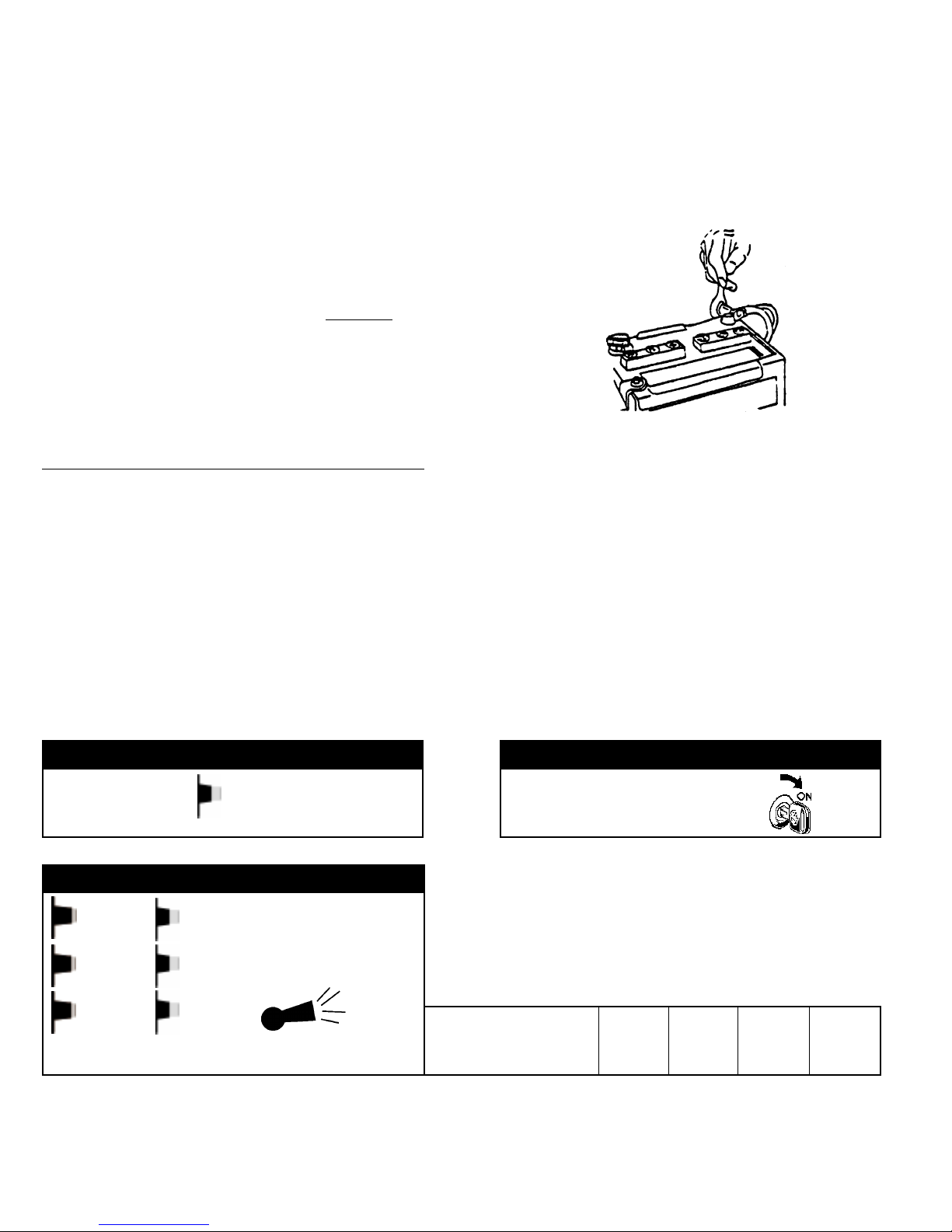
STEP 1
START WITH VALET SWITCH OFF
E
TURN IGNITION KEY TO ON
STEP 2
STEP 3
EE
EE
1 BEEP
EE
VALET SWITCH ON
THEN OFF 3 TIMES
Now press the LOCK button ( hold the button for 3 seconds until the horn sounds ) on all transmitters
that you want to program ( up to 4 ), or continue on to the next step. Remember, when you're
programming more than one transmitter, press the lock button on the first transmitter until the horn
sounds, then press the lock button on the second transmitter, etc.
transmitters at the same time while in programming mode.
HORN SOUNDS
CHANNEL 1
" LOCK "
MEMORY
POSITION
# 1
Never
MEMORY
POSITION
# 2
activate two or more
MEMORY
POSITION
# 3
MEMORY
POSITION
# 4
Page 2
Page 3
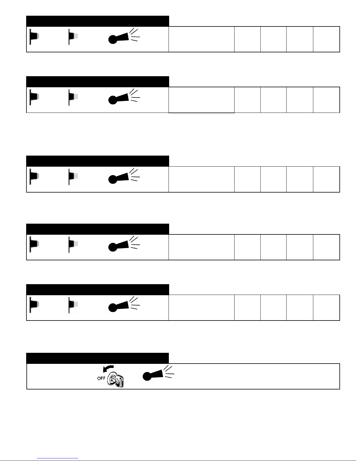
STEP 4
E
VALET SWITCH ON THEN OFF
Now press the UNLOCK button ( hold the button for 3 seconds until the horn sounds ) on all transmitters
that you want to program ( up to 4 ), or continue on to the next step.
E
STEP 5
E
VALET SWITCH ON THEN OFF
If the vehicle does not have the Trunk Release Upgrade Kit installed, proceed to step 6.
If the Trunk Release Upgrade Kit is installed into the vehicle, press the Green button ( hold the button
for 3 seconds until the horn sounds ) on all transmitters that you want to program ( up to 4 ), or
continue on to the next step.
E
STEP 6
E
VALET SWITCH ON THEN OFF
If there are no SECURIKEY+ upgrade kits ( IE: Trunk Release or Remote Starter ) installed into the
vehicle, press the Green button ( hold the button for 3 seconds until the horn sounds ) on all transmitters
that you want to program ( up to 4 ), or continue on to the next step.
E
2 BEEPS
HORN SOUNDS
3 BEEPS
HORN SOUNDS
4 BEEPS
HORN SOUNDS
CHANNEL 2
" UNLOCK "
CHANNEL 3
" TRUNK RELEASE "
CHANNEL 4
" HEADLIGHT "
MEMORY
POSITION
# 1
MEMORY
POSITION
# 1
MEMORY
POSITION
# 1
MEMORY
POSITION
# 2
MEMORY
POSITION
# 2
MEMORY
POSITION
# 2
MEMORY
POSITION
# 3
MEMORY
POSITION
# 3
MEMORY
POSITION
# 3
MEMORY
POSITION
# 4
MEMORY
POSITION
# 4
MEMORY
POSITION
# 4
STEP 7
E
VALET SWITCH ON THEN OFF
Do not program transmitter buttons to this channel. On the SECURIKEY+, the panic feature activates
from the Lock button. Continue on to the next step.
E
STEP 8
E
VALET SWITCH ON THEN OFF
If the Remote Start Upgrade Kit is installed into the vehicle, press the Green button ( hold the button
for 3 seconds until the horn sounds ) on all transmitters that you want to program ( up to 4 ), or
continue on to the next step.
E
STEP 9
TURN IGNITION KEY TO OFF
5 BEEPS
HORN SOUNDS
6 BEEPS
HORN SOUNDS
HORN SOUNDS
CHANNEL 5
" DEDICATED PANIC "
CHANNEL 6
" REMOTE START "
SOFT &
LOUD BEEP
MEMORY
POSITION
# 1
MEMORY
POSITION
# 1
MEMORY
POSITION
# 2
MEMORY
POSITION
# 2
MEMORY
POSITION
# 3
MEMORY
POSITION
# 3
MEMORY
POSITION
MEMORY
POSITION
PROGRAMMING
MODE TERMINA TED
# 4
# 4
Page 3
Page 4
TESTING THE ALARM SYSTEM:
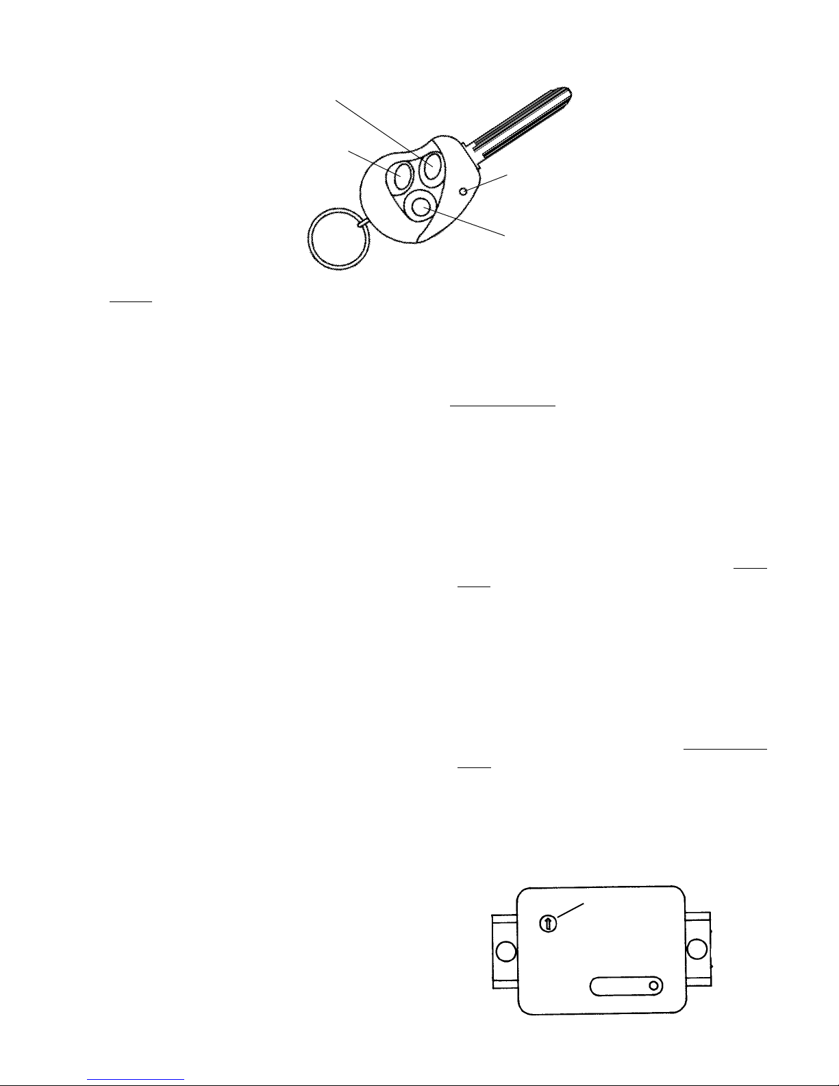
Lock Button
Unlock Button
LED Light
Green Button
A. Test BOTH remote transmitters, one at a time. Press and release the "LOCK" button. If the LED light on
the transmitters fails to glow, you need to check the transmitter battery. (Refer to the section on battery
replacement in the Owner's Manual.)
B. VALET CONTROL SWITCH:
1. Sit in the driver's seat, insert the ignition key and
turn to the ON position.
2. Press the valet control switch and verify that the
LED light responds. Light should go ON and
OFF with actuation of the valet control switch.
3. With the LED indicator light ON, ignition OFF and
key removed, the security system is in the valet
mode and the alarm should not arm. Press and
release the "LOCK" button; all doors will lock
but the LED will not flash. Press and release
the "UNLOCK" button; the driver's door will
unlock.
4. Switch the ignition key ON, and turn the LED
light OFF. Remove the key.
C. ARMING / DISARMING & P ANIC:
1. Put the driver’s window down and close the trunk,
hood and all doors.
2. Press and release the "LOCK" transmitter button.
All doors lock, parking lights flash once, horn
chirps once, headlights come on for 20 seconds
and the LED should flash slowly . (If the parking
lights flash three times and the horn chirps three
times, check for an open trunk, hood or door.)
4. Press and hold the "LOCK" button to test the
"Panic" function. The alarm should blow the
horn in short continuous blasts and the parking
lights and dome lights should be flashing. Press
and release the “LOCK” button to stop “P ANIC”.
D. SHOCK SENSOR:
1. Press and release the "LOCK" button to arm the
system. Wait 10 seconds, then with the open
palm lightly slap the "A" pillar by the driver's
windshield. You should hear short chirps from
the vehicle horn. This is a check of the shock
sensor "WARN-AWAY" function. Allow a few
seconds for the shock to settle, then conduct
the same check at various points around the
vehicle. Sensitivity can be adjusted at the shock
sensor for best response.
2. Slap the vehicle at the "A" pillar with slightly more
force. The vehicle should go into full alarm.
Press and release the "UNLOCK" button to
disarm the system. Rearm the vehicle and
conduct the same check at various points
around the vehicle. Adjust sensitivity at the
shock sensor for the best response.
sensitivity adjustment
3. Press and release the "UNLOCK" transmitter
button. Driver's door unlocks, parking lights flash
(2) times, the horn chirps (2) times, headlights
and dome light come on for 20 seconds.
SHOCK SENSOR
Page 4
Page 5

TESTING THE ALARM SYSTEM [CONTINUED]:
E. DEFECTIVE OR LOST TRANSMITTER:
1. Press and release the "LOCK" button to arm the
system. Use the key to unlock and open the
driver's door. The alarm will sound. Enter the
vehicle, insert the ignition key and turn to the
on position. Press the valet control switch once,
the alarm should deactivate and the vehicle
should now start.
F. AUTOMATIC DOOR LOCK / UNLOCK:
1. With the system disarmed and all doors closed,
insert the ignition key and start the vehicle.
doors should lock when the engine is started.
The doors will not lock if any door is open when
the car starts.
2. Turn the ignition OFF, the engine should stop
and only the driver's door should unlock.
G. REMOTE TRANSMITTER OPERATION:
1. Press and release the "LOCK" button, the system
should arm and lock all doors.
2. Press and release the "UNLOCK" button, the
system will disarm and unlock the driver's door.
All
I. INTRUSION TEST:
1. Rearm the security system by pressing and
releasing the "LOCK" button. Open any door.
The system should simultaneously sound the
horn and flash the parking lights.
2. Disarm the security system by pressing and
releasing the "UNLOCK" button. The system
should sound (4) chirps of the horn, the parking
lights should flash (4) times, indicating vehicle
intrusion.
3. Perform another intrusion test by pressing the
“LOCK” button, wait 10 seconds, then open the
hood. The alarm should sound the horn
indicating vehicle intrusion. Press and release
the "UNLOCK" button to disarm the system and
unlock the driver's door.
4. The LED should indicate the point of intrusion
after disarming the system. Observe the LED
for 1, or 3 flashes. Compare your observations
to the following.
(1) Flash = Shock Sensor or Trunk
(2) Flashes = Hood
(3) Flashes = Vehicle Doors
3. Press and release the "UNLOCK" button again,
the system should unlock all doors.
4. Lock the doors with the vehicle door switch. Press
and release the "UNLOCK" button, all doors
should unlock.
H. HEADLIGHT ACTIV A TION:
1. Press and release the "GREEN" button. The
vehicle’s headlights should turn on for 20
seconds...or until the ignition key is turned on.
THE SYSTEM AUTOMA TICALL Y CLEARS ALL
STORED VIOLATIONS WHEN THE IGNITION
SWITCH IS TURNED TO THE "ON" POSITION.
Page 5
Page 6

PROGRAMMING THE SELECTABLE FEA TURES:
The SECURIKEY+ system offers a number of selectable features that can be changed, allowing you to custom fit the system to your customer. The following is a list of the
features that are selectable and can be changed using the valet switch and any transmitter that is programmed to the system installed in the vehicle.
FEATURE # FUNCTION 1 CHIRP 2 CHIRPS
1 Headlights on for 20 seconds during disarm ON or OFF
2 Headlights on for 20 seconds during arm ON or OFF
3 Automatic ignition controlled door lock ON or OFF
4 Automatic ignition controlled door unlock ON or OFF
5 Auto unlock driver's door only or all doors Driver's Door or All Doors
6 Active or Passive arming Passive or Active
7 Active or Passive door locks Passive or Active
8 Chirp Volume - Soft or Loud Soft or Loud
9 Panic on lock button or option button Option or Lock
10 Trunk Release hold 1 second or 2 presses Hold 1 Sec or 2 Times
T o change the selection of any of these features, follow the step by step programming procedures, and do not allow more than 15 seconds to pass between any two steps or the
system will terminate the programming mode. There is no need to complete the entire programming sequence. After the appropriate features have been changed, simply turn the
ignition key off to terminate the programming mode.
1. Be sure that the SECURIKEY+ system is disarmed, and the lighted valet switch is in the off ( out ) position before you begin.
2. Turn the vehicle's ignition key to the on position.
3. Press then release the L.E.D. valet switch 6 times.
4. Immediately turn the ignition key off then back on.
FEATURE 1 LED Flashes 1 Time Horn Chirps either 1 or 2 Times
To change the selection, press and release the lock button on the transmitter, which will be indicated by the appropriate 1 or 2 chirp signal from the horn. If you do not want to
change this feature, simply press and release the L.E.D. valet switch 2 times to advance to programmable feature number 2.
FEATURE 2 LED Flashes 2 Times Horn Chirps either 1 or 2 Times
To change the selection, press and release the lock button on the transmitter, which will be indicated by the appropriate 1 or 2 chirp signal from the horn. If you do not want to
change this feature, simply press and release the L.E.D. valet switch 2 times to advance to programmable feature number 3.
FEATURE 3 LED Flashes 3 Times Horn Chirps either 1 or 2 Times
To change the selection, press and release the lock button on the transmitter, which will be indicated by the appropriate 1 or 2 chirp signal from the horn. If you do not want to
change this feature, simply press and release the L.E.D. valet switch 2 times to advance to programmable feature number 4.
FEATURE 4 LED Flashes 4 Times Horn Chirps either 1 or 2 Times
To change the selection, press the lock button on the transmitter, which will be indicated by the appropriate 1 or 2 chirp signal from the horn. If you do not want to change this
feature, simply press and release the L.E.D. valet switch 2 times to advance to programmable feature number 5.
FEATURE 5 LED Flashes 5 Times Horn Chirps either 1 or 2 Times
To change the selection, press the lock button on the transmitter, which will be indicated by the appropriate 1 or 2 chirp signal from the horn. If you do not want to change this
feature, simply press and release the L.E.D. valet switch 2 times to advance to programmable feature number 6.
FEATURE 6 LED Flashes 6 Times Horn Chirps either 1 or 2 Times
To change the selection, press the lock button on the transmitter, which will be indicated by the appropriate 1 or 2 chirp signal from the horn. If you do not want to change this
feature, simply press and release the L.E.D. valet switch 2 times to advance to programmable feature number 7.
1 Chirp = Headlights ON During Disarm 2 Chirps = Headlights OFF During Disarm
1 Chirp = Headlights ON During Arm 2 Chirps = Headlights OFF During Arm
1 Chirp = Ignition controlled door locks ON 2 Chirps = Ignition controlled door locks OFF
1 Chirp = Ignition controlled unlock ON 2 Chirps = Ignition controlled unlock OFF
1 Chirp = Ignition controlled unlock DRIVER'S DOOR 2 Chirps = Ignition controlled unlock ALL DOORS
1 Chirp = PASSIVE ARMING ( Automatic Arming ) 2 Chirps = ACTIVE ARMING ( Arm by Remote Only )
FEATURE 7 LED Flashes 7 Times Horn Chirps either 1 or 2 Times
To change the selection, press the lock button on the transmitter, which will be indicated by the appropriate 1 or 2 chirp signal from the horn. If you do not want to change this
feature, simply press and release the L.E.D. valet switch 2 times to advance to programmable feature number 8.
FEATURE 8 LED Flashes 8 Times Horn Chirps either 1 or 2 Times
To change the selection, press the lock button on the transmitter, which will be indicated by the appropriate 1 or 2 chirp signal from the horn. If you do not want to change this
feature, simply press and release the L.E.D. valet switch 2 times to advance to programmable feature number 9.
FEATURE 9 Do not change this feature selection. It should be left in the factory preset ( 1 chirp ) mode. Press and release the L.E.D. valet switch 2
FEA TURE 10 Do not change this feature selection. It should be left in the factory preset ( 2 chirp ) mode. Press and release the L.E.D. valet switch 2
1 Chirp = PASSIVE DOOR LOCKS 2 Chirps = ACTIVE DOOR LOCKS
1 Chirp =SOFT Horn Chirps 2 Chirps = LOUD Horn Chirps
times to advance to programmable feature number 10.
times to terminate the feature programming mode.
Page 6
Page 7

WHAT IS A
RECEIVER CHANNEL
?
The SECURIKEY+ control module includes a
codes. Each receiver channel is reserved for a particular remote control function of the system.
The chart shown below is a diagram of the actual configuration of the memory positions available in the SECURIKEY+ main control
module. As you can see, the module can store transmitter codes in ( 4 ) different memory positions ( A,B,C, & D ) for each of the ( 6 )
different receiver channels ( or functions ). In total, the module is equipped with storage for 24 different transmitter codes, four for each
function.
RECEIVER CHANNEL / SYSTEM FUNCTION
Channel 1 - Lock & Remote Panic
Channel 2 - Unlock
Channel 3 - Trunk Release
Channel 4 - Remote Headlight Activation
Channel 5 - Optional Panic from Green Button
Channel 6 - Remote Starter
6 Channel Receiver
, and each channel can learn and memorize four different transmitter
MEMORY
POSITION A
1A
2A
3A
4A
5A
6A
MEMORY
POSITION B
1B
2B
3B
4B
5B
6B
MEMORY
POSITION C
1C
2C
3C
4C
5C
6C
MEMORY
POSITION D
1D
2D
3D
4D
5D
6D
WHAT IS A
It is important to remember that the description " transmitter code "
does not refer to an actual transmitter, but instead refers to a button
of a transmitter. This alone is the one key point that many security
technicians do not completely understand, and this can cause some
confusion. With that in mind, please refer to the chart at the right.
As you can see in these diagrams, each SECURIKEY+ transmitter is
capable of producing 7 different
button (s) that are shaded black. In the industry , the codes are typically
referred to as
SECURIKEY+ key is a
Another important fact is that no two SECURIKEY+ transmitters are
identical. This is actually not a fact, and the fact is that out of every
16,777,216 transmitters produced, two will be identical; but for this
discussion it is safe to say that no two SECURIKEY+ transmitters are
identical. The reason that this point comes up is to understand that if
you have ( 2 ) SECURIKEY+ transmitters, you have access to 14
different transmitter codes,
Some other important facts that you will want to know and understand
are;
An individual transmitter code ( button ) can be learned and stored
ð
into all 4 memory positions of a single receiver channel.
Each individual transmitter code can be learned and stored into
only one receiver channel of each system. This means that a
ð
transmitter button ( code ) can not be learned to activate both
receiver channel 1 ( lock ) and receiver channel 2 ( unlock ).
When a new transmitter is learned, any code stored in memory
position D is erased. The new code is stored in position A, and
ð
the other codes are advanced ( A to B ; B to C ; C to D ).
transmitter channels
TRANSMITTER CODE
transmitter codes
, and as you can see the
7 channel transmitter
and not
7 codes twice.
by activating the
.
TRANSMITTER
CODE NUMBER
TRANSMITTER CODE
TRANSMITTER CODE
TRANSMITTER CODE
TRANSMITTER CODE
TRANSMITTER CODE
TRANSMITTER CODE
TRANSMITTER CODE
Page 7
?
TRANSMITTER BUTTON
ACTIVATION
1
2
3
4
5
6
7
Page 8

WHY IS THIS INFORMATION IMPORTANT ?
Let's first consider that any SECURIKEY+5 transmitter code or button can be programmed into any one of the six receiver channels of
the system. The system will allow you to program transmitter code 1 ( lock button ) into receiver channel 4 ( headlight activation ), but
since the lock and unlock buttons are clearly marked with icons describing their function, these two buttons should always be programmed into receiver channels 1 and 2.
Since the system will allow you to program these buttons into the wrong receiver channel, it is very important that you listen to the chirps
from the horn when you enter the programming mode. The horn will always tell you which receiver channel that you have progressed into
for programming; just simply count the number of chirps from the horn.
Now, if you have mistakenly programmed the lock button into receiver channel 4, when you test the system the lock button will not lock
the doors or arm the alarm, but it will turn the headlights on, as this is the correct function of receiver channel 4. Next when you attempt
to re - program that same transmitter, you find that when you advance to receiver channel 1, then press the lock button, the system will
not learn the remote ( indicated by the loud horn chirp ). It is important to know that this is not a defective transmitter or module, and you
will just need to " clear " the transmitter code from the incorrect receiver channel.
CLEARING TRANSMITTER CODES FROM MEMORY:
"QUICK CLEARING" PROCEDURE:
A. This procedure will erase all previously coded transmitter buttons, clearing the way to allow
trouble free programming of the required transmitters. After you have cleared all transmitter
codes, you
system memory, proceed as follows:
must reprogram the original transmitter to the system. To clear the security
Disarm the system. Valet/LED control switch should
be in the "OFF" position before you start.
Insert ignition key, turn to "ON" position.
Press the valet control switch IN then OUT 3 times.
(The horn will chirp (1) time and L.E.D. flashes (1)
time to indicate the system is in the program mode.)
Turn ignition key "OFF" to "ON" 3 times rapidly. This
procedure initiates the "quick clearing" mode.
OFF
ON
Short Chirp
followed by
=
long chirp
OFF
Press to
disarm
ON
Valet control
switch IN
Short Chirp
followed by
=
long chirp
OFF
Valet control
switch OUT
Valet control
switch OUT
3 times =
ON
(Horn 1 chirp)
(LED 1 flash)
Long chirp
=
Turn ignition "OFF"
OFF
Page 8
=
SYSTEM MEMORY CLEARED
Page 9
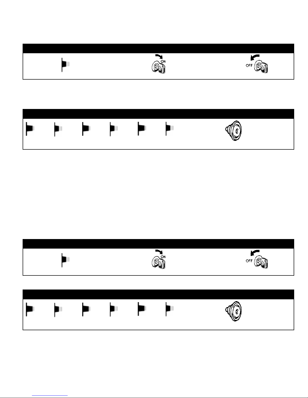
TURNING THE ARM / DISARM CHIRPS ON:
STEP 1
THEN
THEN
E
START WITH VALET SWITCH OFF TURN IGNITION KEY TO ON
STEP 2
THEN
E
WITHIN 5 SECONDS, VALET SWITCH ON AND THEN OFF 3 TIMES
E
E
E
TURNING THE ARM / DISARM CHIRPS OFF:
NOTE : Whenever the chirps are turned off, the 4 chirp intrusion indicator and 3 chirp defective zone
indicator will always operate. These are important warnings to you that something has happened, and they
can not be turned off.
EE
HORN SOUNDS 1 CHIRP = CHIRPS ON
TURN IGNITION KEY TO OFF
1 CHIRP =
CHIRPS ON
E
START WITH VALET SWITCH OFF TURN IGNITION KEY TO ON
E
WITHIN 5 SECONDS, VALET SWITCH ON AND THEN OFF 3 TIMES
E
EE
THEN
STEP 1
STEP 2
EE
Page 9
THEN
TURN IGNITION KEY TO OFF
THEN
HORN SOUNDS 2 CHIRPS = CHIRPS OFF
2 CHIRPS =
CHIRPS OFF
Page 10

TROUBLESHOOTING - Transmitters:
SYMPTOM
One or both of my transmitters doesn't work any more ( stopped working ).
HELPFUL HINT : If a transmitter has been programmed to the system at one time, it will remain
programmed. Disconnecting the vehicle's battery or removing the transmitter battery will not erase
transmitter codes from the SECURIKEY+ system's memory. The only way transmitter codes are removed
from the system memory is by deliberately programming different transmitters, deliberately bumping
the codes out of memory, or deliberately erasing the system's memory !
DO NOT reprogram transmitters that you know are already programmed to the system. Instead, first
check to see if the transmitter needs to be realigned to the system.
BEGIN TROUBLESHOOTING
Does the Red L.E.D. on the transmitter flash rapidly and flash
brightly when any of the transmitter buttons are pressed ?
YES
Were the transmitters in question ever
programmed to operate the system ?
Replace the transmitter battery, then test the
transmitter. Does the system operate now ?
NO
NO
*Press and release
the LOCK button on
the transmitter two
times within 1 second.
*Try pressing the
LOCK button 10 times
within five seconds.
*Program transmitter
to the system.
*If a programming
attempt failed, you
will need to erase
existing transmitter
codes first. ( page 8 ).
QUESTION
Does the system now operate properly ?
YES
Diagnosis
Completed.
Defective transmitter .
Replace transmitter.
NO
YES
Diagnosis
Completed.
YES NO
Start again from the
beginning.
NOYES
Does the transmitter
L.E.D. flash now ?
Defective transmitter .
Replace transmitter.
Page 10
Page 11

TROUBLESHOOTING - Horn / Chirps:
My system does not chirp when Arming and Disarming.
SYMPTOMS
HELPFUL HINTS :
1) The arm and disarm chirps are turned on and off by using the L.E.D. / Valet switch in combination
with the ignition switch. The SECURIKEY+ system does not use dip switches to turn the chirps on
and off.
2) When the chirps are turned off, the 3 chirp ( armed with a door open - "defective zone" ) and 4 chirp
( disarm after alarm trigger - "intrusion alert" ) signals will always remain on. There is no way to defeat
the 3 and 4 chirp signals.
I cannot turn my chirps on ( or off ).
The alarm will set, but will not sound when opening a door.
BEGIN TROUBLESHOOTING
Open the driver's door, then press the LOCK button to arm
the system. Did the horn chirp 3 times ?
YES
*Turn the chirps ON according to the
procedure on page 9.
QUESTION
Does the system operate properly now ?
YES
Diagnosis
Completed.
The procedure to turn
chirps on will not
work.
NO
QUESTION
T urn the ignition key to ON, then push the L.E.D.
/ Valet switch to the ON ( IN ) position. Does the
dash L.E.D. turn On ?
NO
Does the SECURIKEY+ system make the horn
sound under any conditions, ( IE: full trigger, prewarn, or remote panic ?
YES
*Repair BROWN door
trigger wire from
alarm, or the defective
door pin switch, then
start over.
*Inspect and repair
GREEN with RED
STRIPE horn wire
from alarm harness.
NO
QUESTION
Does the SECURIKEY+ system make the horn
sound under any conditions, ( IE: full trigger, prewarn, or remote panic ) now ?
YES
*Repeat procedure to
turn chirps on, but
this time quicker. You
have only 5 seconds
to complete this.
*Repair connection
on YELLOW ignition
wire on the alarm
harness.
NO
Page 11
YES
Start again from the
beginning.
NO
Defective module.
Replace module.
Page 12

TROUBLESHOOTING:
4. Reading the Connection Points at the 24 pin Main Alarm Connector :
A. When checking the 24 pin main alarm connector, be sure that it is disconnected from the alarm
control module. All other connections to the main alarm harness should remain connected.
123456789101112
13 14 15 16 17 18 19 20 21 22 23 24
24 PIN MAIN ALARM CONNECTOR
( TERMINAL VIEW )
PIN 1 - DOOR TRIGGER - BROWN WIRE
Pin 1 to Ground - Approximately 12 Volts with all doors
closed.
0 Volts with LF or RF door opened.
PIN 2 - HOOD PIN SWITCH - DARK GREEN WIRE
Pin 2 to Ground - No continuity with hood lid closed.
Continuity with hood lid opened.
PIN 3 - L.E.D. (+) - RED WIRE (Refer to NOTE below)
PIN 4 - L.E.D. (-) - LIGHT BLUE WIRE (Refer to NOTE below)
PIN 5 - ALL DOOR UNLOCK #1 - PINK w/ WHITE STRIPE WIRE
Pin 5 to Ground - Approximately 12 Volts.
0 Volt pulse when LF door unlock switch
is activated.
PIN 6 - BLANK
PIN 7 - LF DOOR UNLOCK FROM RELAY - DARK BLUE w/ WHITE
STRIPE WIRE
Pin 7 to Ground - 0 Volts.
Approximately 12 Volt pulse when LF door
unlock switch is activated.
PIN 8 - LF DOOR UNLOCK TO SOLENOID - WHITE WIRE
Pin 8 to Ground - 0 Volts.
Approximately 12 Volt pulse when LF door lock
switch is activated.
PIN 9 - DRIVER'S DOOR UNLOCK SOURCE - ORANGE w/ WHITE
STRIPE WIRE
Pin 9 to Ground - Always approximately 12 Volts.
PIN 10 - HORN RELAY - GREEN w/ RED STRIPE WIRE
Pin 10 to Ground - Approximately 12 Volts.
0 Volts when horn switch is activated.
PIN 11 - TAILLIGHT RELAY - YELLOW/GREEN STRIPE WIRE
Pin 11 to Ground - Approximately 12 Volts.
0 Volts when Parking Lamp switch is
activated.
PIN 12 - CTSY LIGHT SOURCE - BLACK w/ WHITE STRIPE WIRE
Pin 12 to Ground - Always continuity.
PIN 13 - (+) 12 VOLT BATTERY SOURCE - RED WIRE
Pin 13 to Ground - Always approximately 12 Volts.
PIN 14 - CHASSIS GROUND SOURCE - BLACK WIRE
Pin 14 to Ground - Always continuity.
PIN 15 - (+) 12 VOLT IGNITION SOURCE - YELLOW WIRE
Pin 15 to Ground - Approximately 12 Volts when ignition key
switched to " RUN " and " START ".
0 Volts when ignition key switched to
" LOCK " and " ACCESSORY ".
PIN 16 - TRUNK TRIGGER - BROWN w/ WHITE STRIPE WIRE
Pin 16 to Ground - Approximately 12 Volts with trunk lid and all
doors closed.
0 Volts with trunk lid opened.
PIN 17 - ALARM CONTROL SWITCH - GREY WIRE
PIN 18 - ALARM CONTROL SWITCH - BLACK w/ ORANGE STRIPE WIRE
Pin 17 to Pin 18 - No continuity with alarm control switch in OFF
(OUT ) position.
Continuity with alarm control switch in ON(IN)
position.
PIN 19 - BLANK
PIN 20 - DISARM - PINK w/BLACK STRIPE WIRE
Pin 20 to Ground- Approximately 12 Volts.
0 Volts when LF door key switch is rotated to
unlock.
PIN 21 - DOOR LOCK WIRE - PINK WIRE
Pin 21 to Ground - Approximately 12 Volts.
0 Volts when LF door lock switch is activated.
0 Volts when LF door key switch is rotated to
lock position.
PIN 22 - STAR TER DISABLE RELAY - ORANGE WIRE
Pin 22 to Ground - Approximately 12 Volts when ignition key
switched to " RUN " and " START ".
0 Volts when ignition key switched to
" LOCK " and " ACCESSORY ".
PIN 23 - HEADLIGHT RELAY - BLUE WIRE
Pin 23 to Ground - Approximately 12 Volts.
0 Volts when Headlight switch is activated.
PIN 24 - COURTESY LIGHT - GREEN w/ WHITE STRIPE WIRE
Pin 24 to Ground - Approximately 12 Volts with all doors closed
0 Volts with LF or RF door opened.
NOTE: The alarm control module must be connected to the
security main harness in order to test pins 3 and 4.
Page 12
 Loading...