

Audiovox AV-990 Owner's Manual
OO
WNER'S MANUWNER'S MANU
O
WNER'S MANU
OO
WNER'S MANUWNER'S MANU
ALAL
AL
ALAL
MANUEL DE L'UTILISAMANUEL DE L'UTILISA
MANUEL DE L'UTILISA
MANUEL DE L'UTILISAMANUEL DE L'UTILISA
MANUMANU
MANU
MANUMANU
AL DE OPERAAL DE OPERA
AL DE OPERA
AL DE OPERAAL DE OPERA
REW FF
AA
VV
A
AA
-990-990
V
-990
VV
-990-990
CIONCION
CION
CIONCION
TEURTEUR
TEUR
TEURTEUR
DIGITAL AM/FM/MPX RADIO WITH
AUTO-REVERSE CASSETTE PLAYER
RADIO DIGITAL AM/FM/MPX AVEC
LECTEUR DE CASSETTES À INVERSION AUTOMATIQUE
RADIO DIGITAL AM/FM/MPX CON
TOCACINTAS CON INVERSION AUTOMATICA DE LA CINTA

INSTALLATION INSTRUCTIONSINSTALLATION INSTRUCTIONS
INSTALLATION INSTRUCTIONS
INSTALLATION INSTRUCTIONSINSTALLATION INSTRUCTIONS
This unit is designed for installation in cars, trucks, and vans with an existing radio opening. In many
cases, a special installation kit will be required to mount the radio to the dashboard. These kits are
available at electronics supply stores and car stereo specialist shops. Always check the kit application
before purchasing to make sure the kit works with your vehicle. If you need a kit but cannot find it available,
call our toll-free “HELP” line.
UNIVERSAL INSTALLATION
1. Inspect the Existing Radio Opening
A. Use the trimplate supplied with the radio to cover the existing dashboard opening. If it completely
covers the opening, you can install the radio without an installation kit. If it does not cover the
opening, you will need an installation kit.
B. Check that there will be sufficient space behind the dashboard for the radio chassis.
2. Wire the Radio to the Vehicle’s Wiring
A. In most cases, it is easier to wire the radio before mounting it. Place the radio near the dashboard
so the wires can be led through the opening.
INSTALLATION INSTRUCTIONSINSTALLATION INSTRUCTIONS
INSTALLATION INSTRUCTIONSINSTALLATION INSTRUCTIONS
INSTALLATION INSTRUCTIONS
B. Carefully follow the wiring diagram in this manual and make certain all connections are secure and
insulated with wire nuts or electrical tape to insure proper operation of the unit.
C. After completing the wiring, turn the unit on to confirm operation (ignition switch must be “on”). If
unit does not operate, re-check all wiring until the problem is corrected. Once proper operation is
achieved, turn off unit and ignition switch, and proceed with final mounting of the radio.
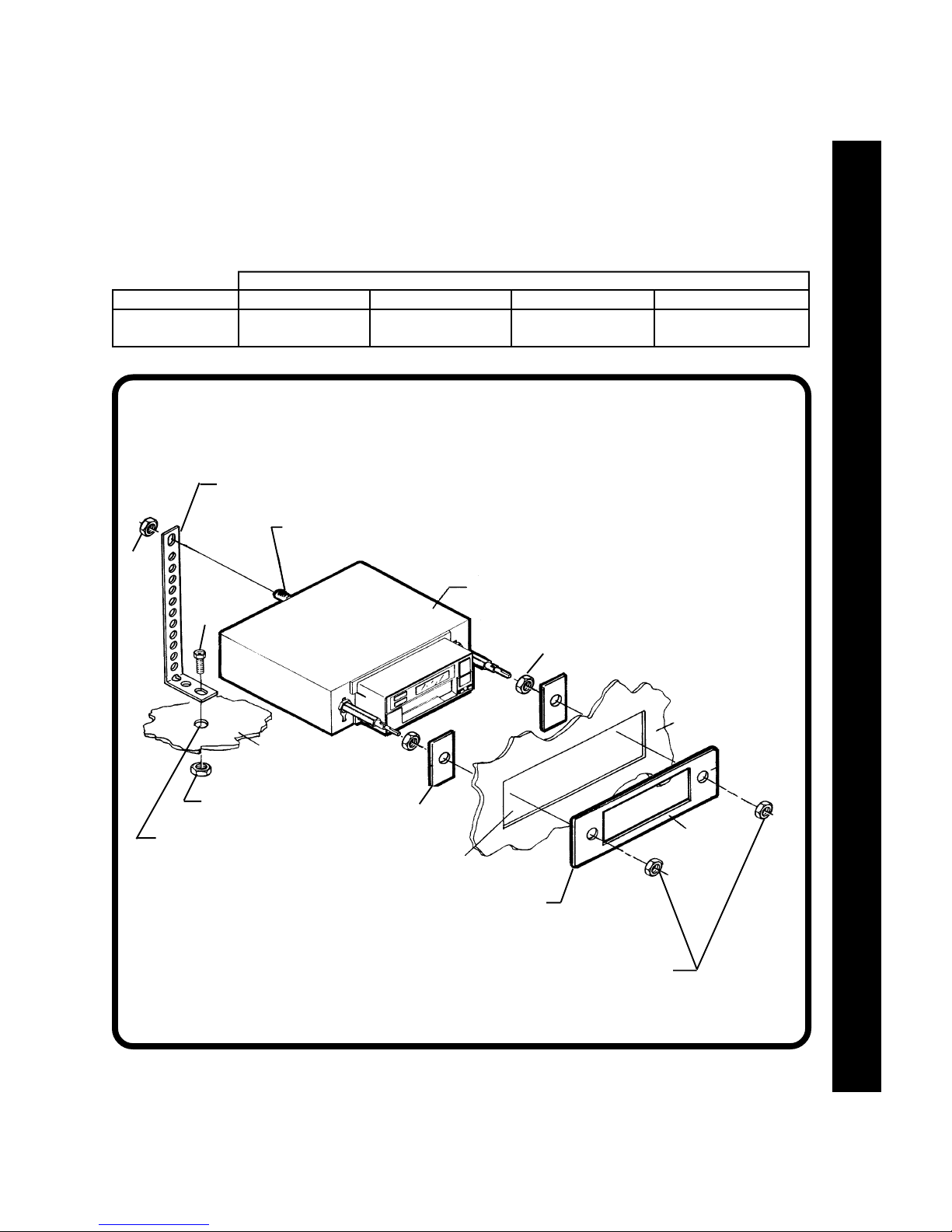
3. Mounting the Radio
A. Thread a shaft nut half-way down each radio shaft.
B. Place a metal back-up plate on each radio shaft against the shaft nut.
C. Position the radio behind the dashboard opening so that the back-up plates are snug against the
back of the opening. Adjust the shaft nuts behind the back-up plates so that the desired amount
of radio nosepiece extends through the opening. The best appearance is usually achieved when
there is just enough of the radio extending to be flush with the front of the trimplate.
D. Place the trimplate over the front of the radio and secure it with a shaft nut on each radio shaft.
E. Attach one end of the perforated support strap (supplied) to the screw stud on the radio using the
hex nut provided. Bend the strap to position it as necessary.
CAUTION: The rear of the radio must be supported with the strap to prevent damage to the dashboard
from the weight of the radio or improper operation due to vibration.
F. Install knobs on the radio.
INSTALLATION USING KITS
1. If your vehicle requires the use of an installation kit to mount this radio, follow the instructions included
with the installation kit to attach the radio to the mounting plate supplied with the kit.
2. Wire and test the radio as described in section 2 above.
3. Install the radio/mounting plate assembly to the sub-dashboard according to the instructions of the
installation kit.
4. Attach the support strap to the radio and dashboard as described in section 3-E above.
5. Replace the dashboard trimpanel and install knobs on the radio shafts.
11
1
11
TOLL-FREE INSTALLATION ASSISTANCETOLL-FREE INSTALLATION ASSISTANCE
TOLL-FREE INSTALLATION ASSISTANCE
TOLL-FREE INSTALLATION ASSISTANCETOLL-FREE INSTALLATION ASSISTANCE
The installation andwiring connections forthis unit are so simple, we doubtyou'll need ourhelp, but, ifyou
do, we're here to help you. Just call our toll-free telephone assistance line at (800) 645-7102 during the
days and hours shown (U.S.A. and Canada only).
TIME ZONE
DAY
MON.-FRI.
SATURDAY
PERFORATEDSTRAP
HEX
NUT
PACIFIC
5:30AM - 4PM
6AM - 2PM
UNIVERSAL INSTALLATIONUNIVERSAL INSTALLATION
UNIVERSAL INSTALLATION
UNIVERSAL INSTALLATIONUNIVERSAL INSTALLATION
SCREWSTUD
MOUNTAIN
6:30AM - 5PM
7AM - 3PM
RADIO
CENTRAL
7:30AM - 6PM
8AM - 4PM
EASTERN
8:30AM - 7PM
9AM - 5PM
INSTALLATION INSTRUCTIONS
INSTALLATION INSTRUCTIONSINSTALLATION INSTRUCTIONS
INSTALLATION INSTRUCTIONSINSTALLATION INSTRUCTIONS
SCREW
METALPARTOF
DASHBOARD
HEXNUT
DRILLHOLEIFNECESSARY
BACK-UPPLATE
EXISTINGOPENING
TRIMPLATE
SHAFTNUT
SHAFTNUTS
DASHBOARD
22
2
22
WIRING DIAGRAMWIRING DIAGRAM
WIRING DIAGRAM
WIRING DIAGRAMWIRING DIAGRAM
RADIO WIRINGRADIO WIRING
RADIO WIRINGRADIO WIRING
RADIO WIRING
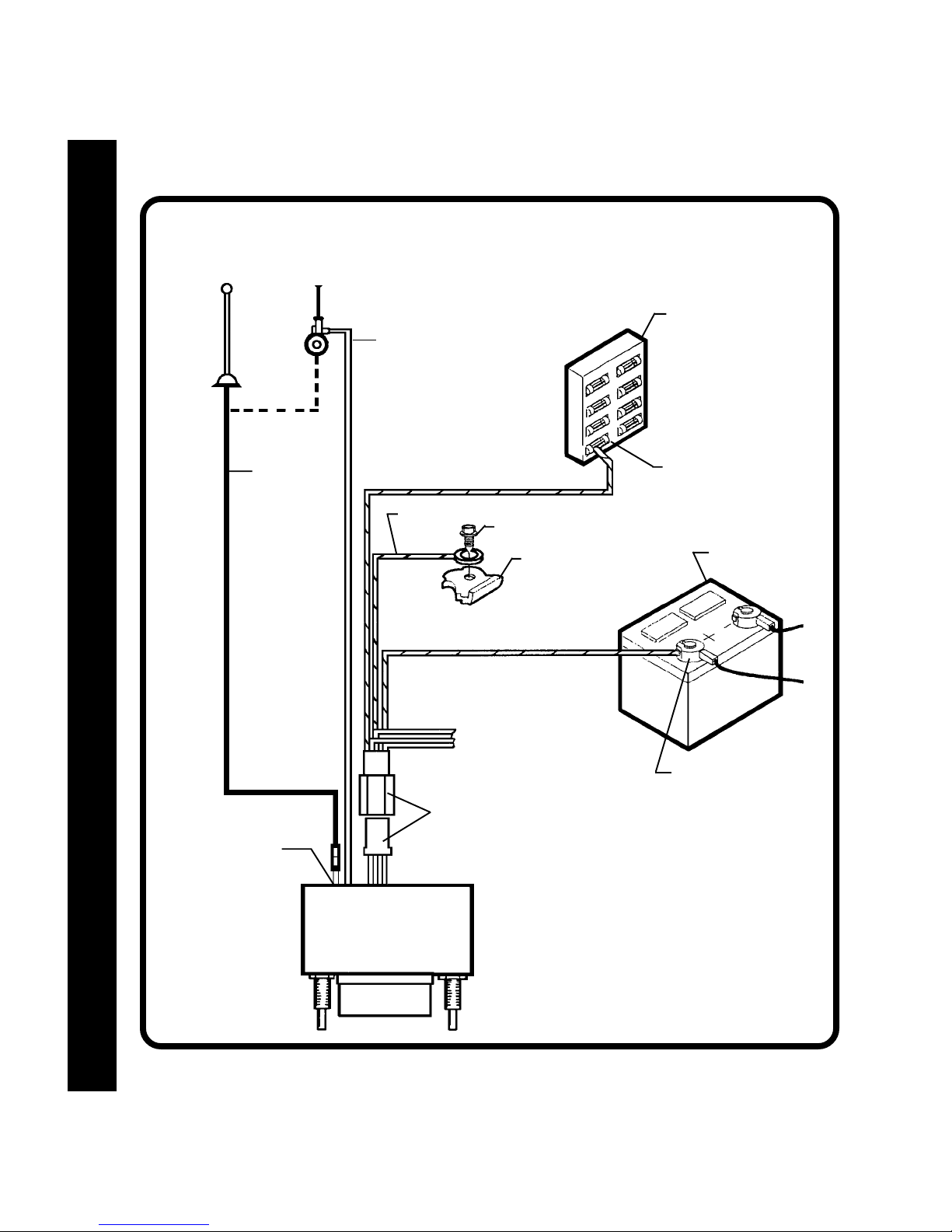
ANTENNA
AUTOMATIC
ANTENNA
EXISTING
ANTENNA
CABLE
PINK
IMPORTANT
THEPINKWIRECANBEUSED
TOREMOTELYACTIVATEAN
AUTOMATICANTENNAORAN
EXTERNALAMPLIFIER(SEE
ANTENNAORAMPLIFIERMANUAL).
ORANGEw/WHITESTRIPE
BLACKw/WHITESTRIPE
SCREW
METALPARTOFDASH
(DRILLHOLEIFNECESSARY)
GREENw/WHITESTRIPE
IMPORTANT
THISWIREMUSTBECONNECTEDASSHOWN
ORRADIOWILLNOTOPERATEPROPERLY
FUSEBLOCK
"RADIO"OR
"ACCESSORY"FUSE
CARBATTERY
33
3
33
ANTENNASOCKET
ONREAROFRADIO
SEEPAGE 11OR12
FORSPEAKERWIRING
(RED,YELLOW,WHITE,BLUE,
VIOLET,&LIGHTGREEN)
9PINPLUGS
POSITIVE(+)TERMINAL12
VOLTBATTERY
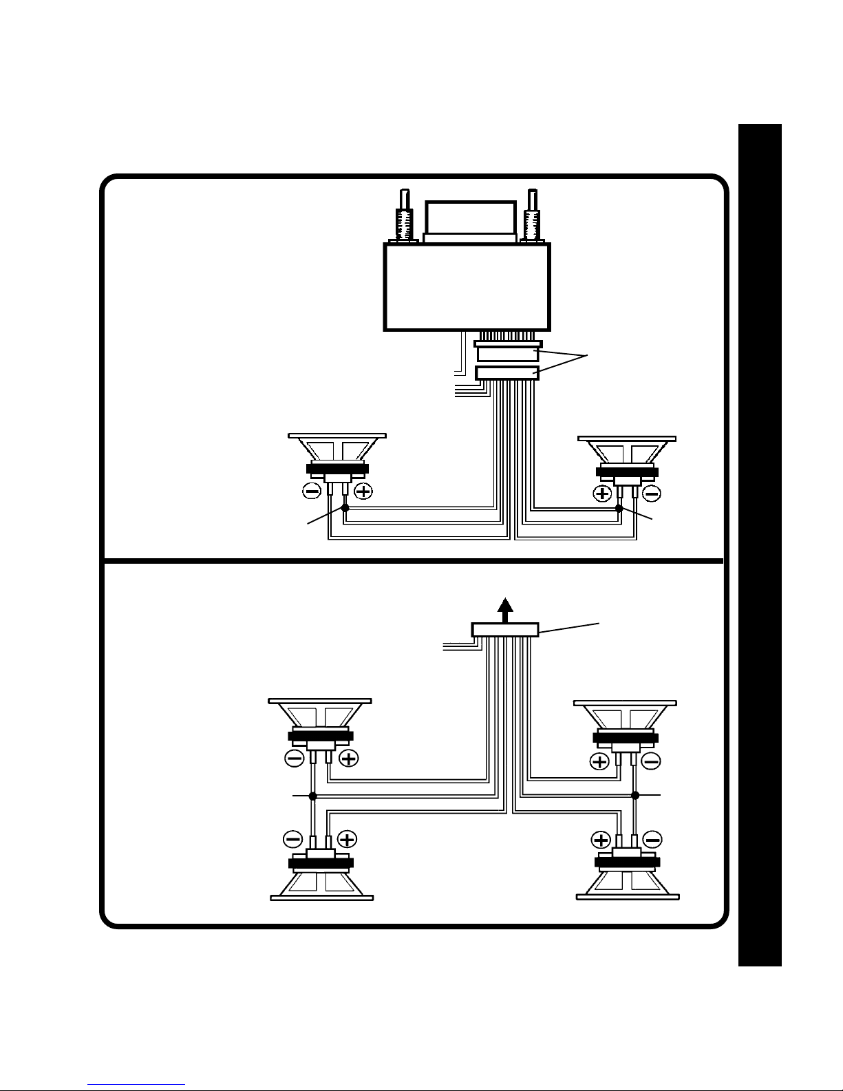
2-SPEAKER2-SPEAKER
2-SPEAKER
2-SPEAKER2-SPEAKER
SYSTEMSYSTEM
SYSTEM
SYSTEMSYSTEM
SPEAKER WIRINGSPEAKER WIRING
SPEAKER WIRING
SPEAKER WIRINGSPEAKER WIRING
RADIO
SPEAKER WIRING
SPEAKER WIRINGSPEAKER WIRING
SPEAKER WIRINGSPEAKER WIRING
4-SPEAKER4-SPEAKER
4-SPEAKER
4-SPEAKER4-SPEAKER
SYSTEMSYSTEM
SYSTEM
SYSTEMSYSTEM
SEEPAGE3FORRADIOWIRING
(BLACKw/WHITESTRIPE,
ORANGEw/WHITESTRIPE,
GREENw/WHITESTRIPE&PINK)
LEFTSPEAKER
SPLICE
SEEPAGE3FORRADIOWIRING
(BLACKw/WHITESTRIPE,
ORANGEw/WHITESTRIPE,
GREENw/WHITESTRIPE&PINK)
LEFTFRONTSPEAKER
WHITE
RED
VIOLET
TORADIO
9PINPLUGS
RIGHTSPEAKER
BLUE
YELLOW
LIGHTGREEN
RIGHTFRONTSPEAKER
SPLICE
9PINPLUG
SPLICE
LEFTREARSPEAKER
WHITE
VIOLET LIGHTGREEN
RED
BLUE
YELLOW
RIGHTREARSPEAKER
SPLICE
44
4
44
OPERATING INSTRUCTIONSOPERATING INSTRUCTIONS
OPERATING INSTRUCTIONS
OPERATING INSTRUCTIONSOPERATING INSTRUCTIONS
OPERATING INSTRUCTIONSOPERATING INSTRUCTIONS
OPERATING INSTRUCTIONSOPERATING INSTRUCTIONS
OPERATING INSTRUCTIONS
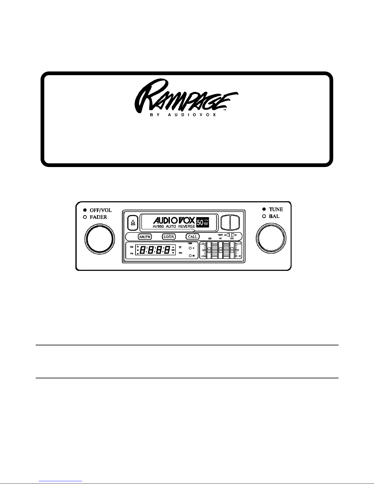
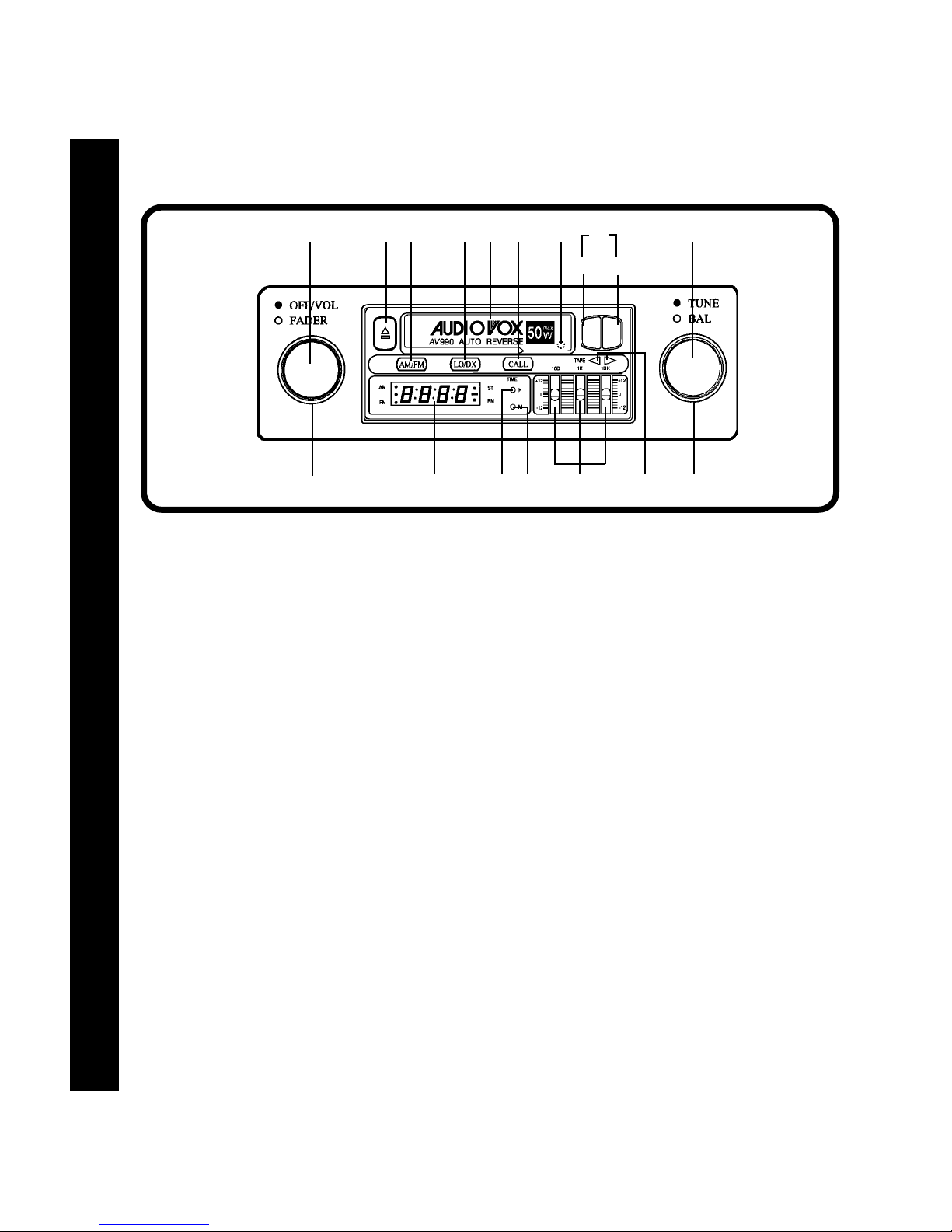
ON-OFF SWITCH/VOLUME CONTROL
1
Rotate this knob to the right to turn the unit on.
Continuerotationuntildesiredvolumelevelisobtained.
2 LEFT/RIGHT BALANCE CONTROL
Rotate this knob to the left orrighttoobtainthe desired
balance between the left and right channel speakers.
3 FRONT/REAR FADER CONTROL
Rotate this knob to the right orlefttoobtainthe desired
balance between front and rearspeakersin4 speaker
installations. When used in conjunction with the Left/
Right Balance Control 2, you have full4-way stereo
balance capability.
4 3-BAND EQUALIZER CONTROLS
These controls permit precise tone adjustment in
three frequency ranges from bass (100 Hz) to midrange (1 KHz) to treble(10KHz). Moving eachcontrol
upward will emphasize that range, while moving it
downward will de-emphasize that range. Each slide
control is capable of varying the response from the
mid-position (flat) setting upward by 12 dB or downward by 12 dB, for a total variation of 24 dB.
5 AM/FM BAND SELECTOR
Each time this button is pressed, the radio band
55
5
55
changes. The selected radio band is shown by the
indicator for AM or FM on the display panel.
bl 8
bo1 bq 5 6 br 7
bn bm
REW FF
3 9 btb s bp4 2
6 FM LOCAL/DISTANT SELECTOR
This two position switch is incorporated to allow
maximum reception in both weak and strong FM
signal areas. For normal reception conditions
when receiving a wide range of signals including
weak or distant stations,the switch should beinthe
released (out) position, which will allow maximum
signal to the receiver. When in anextremelystrong
(local) signal area, push the switch in to the Local
setting. This will eliminate weak signals and suppress overly strong signals soasto avoid overloading the receiver input. When moving out of the
strong signal area, return the switch to the Distant
(out) setting.
NOTE: The Local/Distant Selector only affectsFM
signals, and will have no effect on AM
reception.
7 MANUAL TUNING CONTROL
Rotate this knob to the left or right to select a radio
station. The selected frequency will be shown by
the digital read-out on the display panel.
8 AM ANTENNA TRIMMER
It is very imporatnt to adjust the Antenna Trimmer
for optimum AM reception. The antenns trimmer is
located at the back of the cassette deck behindthe
the tape door. Adjust it as follows:

1. Tune in a weak station around 1400 KHz on the
AM band.
2. Push the tape door open and locate the antenna
trimmer at the back of the cassette deck.
3. Using a small screwdriver, slowly adjust the
trimmer for maximum output from the radio.
NOTE: The Antenna Trimmer only affects AM
reception, and will have no effect on FM
reception. The trimmer only needs to be
adjusted when the radio is first installed
and at any time a change is made to the
vehicle antenna (replacing the mast, etc.).
boPROGRAMSELECTOR
To manually reverse tape direction and play the
other side of thecassette, lightly push boththeFast-
Forward bm and Rewind bn buttons at the same
time. The change of direction will be shown by the
TapeDirectionIndicatorsbp.
bpTAPEDIRECTIONINDICATORS
Thesearrows show the direction of tape play and will
change when the program is changed either automatically at the end of play on one side of the
cassetteor manually by the Program Selector bo.
OPERATING INSTRUCTIONS
OPERATING INSTRUCTIONSOPERATING INSTRUCTIONS
OPERATING INSTRUCTIONSOPERATING INSTRUCTIONS
9 DISPLAY PANEL
The digital display of the radio frequency and time
are shown on thispanel as well asindicators for AM,
FM, and stereo reception.
bl CASSETTE DOOR
Hold the cassette with theexposed tape edgeto the
right and insert it into the cassette door. Depress
fully until the cassette is engaged and begins playing. When the cassette reaches the end of the side
of the tape being played, the unit will automatically
change direction of play, as shown by the Tape
DirectionIndicatorsbp,andplaytheothersideofthe
cassette.
bmFAST-FORWARDBUTTON(FF)
Pushing the Fast-Forward button will causethetape
to move rapidly in the forward direction of play. To
stop Fast-Forward movement, lightly push the Re-
windbuttonbnuntil the Fast-Forward button disen-
gages.
bq EJECT BUTTON ( )
Tapeplaybackis stopped and the cassette is ejected
by pressing this button, which also has the function
of switching over to radio operation.
NOTE: Never leave a cassette engaged in the
player when notin use. Doingso can cause
damage to the cassette and/or mechanism.
Always press the eject button and remove
the cassette when leaving the vehicle.
br DISPLAYCALLSELECTOR(CALL)
During radio operation, the stationfrequency will be
shown on the display panel. Pressingthisbutton will
cause the time to be displayed for 5 seconds before
returning to frequency read-out.
During cassette operation, the time will always be
shown on the display panel.
bsHOUR ADJUST BUTTON (H)
This button is used to adjust the hours on the builtin quartz clock. The button is recessed to prevent
accidental engagement so a toothpick, pen point or
similar object should be used to activate it.
bnREWINDBUTTON(REW)
Pushing the Rewind button will cause the tape to
move rapidly in the reverse directionofplay. To stop
Rewind movement, lightly push the Fast-Forward
buttonbmuntil the Rewind button disengages.
SETTING THE CLOCKSETTING THE CLOCK
SETTING THE CLOCK
SETTING THE CLOCKSETTING THE CLOCK
1. With the vehicle ignition switch “on”, turn the unit off or insert a cassette into the tape door so that the
time is showing on the display panel.
2. Using atoothpick, pen point orsimilar thin object,press the Hour Adjustbutton bs to adjustthe hours
to the correct setting.
3. Using a toothpick, pen point or similar thin object, press the Minute Adjust button bt to adjust the
minutes to the correct setting.
bt MINUTE ADJUST BUTTON (M)
This button is used toadjusttheminutes on the builtin quartz clock. The button is recessed to prevent
accidental engagement so a toothpick, pen point or
similar object should be used to activate it.
66
6
66
SPECIFICATIONSSPECIFICATIONS
SPECIFICATIONS
SPECIFICATIONSSPECIFICATIONS
CARE AND MAINTENANCECARE AND MAINTENANCE
CARE AND MAINTENANCE
SPECIFICATIONS / CARE AND MAINTENANCESPECIFICATIONS / CARE AND MAINTENANCE
SPECIFICATIONS / CARE AND MAINTENANCESPECIFICATIONS / CARE AND MAINTENANCE
CARE AND MAINTENANCECARE AND MAINTENANCE
SPECIFICATIONS / CARE AND MAINTENANCE
The radio portionofyour new soundsystem does not requireany maintenance. We recommend youkeep
this manual for general reference of the many features found in this unit.
As with any cassette player, the cassette section of this sound system does require a minimum of
maintenanceto keep it in good working condition. Thefollowing simple care and maintenance suggestions
should be followed to prevent malfunctions of the cassette system.
Cassette Care:
1. Purchase a cassette cleaning kit from your local
retail store. Use it! At least every 20 to 30 hours
of operation you must clean the cassette mechanism. A dirty cassette player will have a poor
sound.
2. Do not use cassettes that exceed 45 minutes of
play on each side.
3. Do notinsert a cassettethat appears tobe broken,
twisted or dirty or with loose or torn labels on it.
4. Always keep your cassettes away from direct
sunlight or exposure to sub-freezingconditions. If
a cassette is cold, allow it to warm up before use.
77
7
77
5. Do not keep a cassette in the player when not in
use.
Size:
Operating Voltage:
Output Power:
Output Wiring:
Output Impedance:
Tuning Range:
Sensitivity:
FM Stereo Separation:
Tape Frequency Response:
Tape S/N Ratio:
Wow & Flutter:
* Specifications are subject to change without notice.
7" W x 2" H x 5-1/2" D
178mm x 50mm x 137mm
12 volts DC, negative ground
50 watts maximum
( 25 watts x 2 channels)
Floating-ground type designed for 4 speaker use.
May also be used with 2 speakers.
Compatible with 4-8 ohm speakers
AM: 530-1,720 KHz.
FM: 87.5-107.9 MHz.
AM: 15 uv.
FM: 2.5 uv.
30 dB
50-10,000 Hz.
50 dB
0.15% WRMS
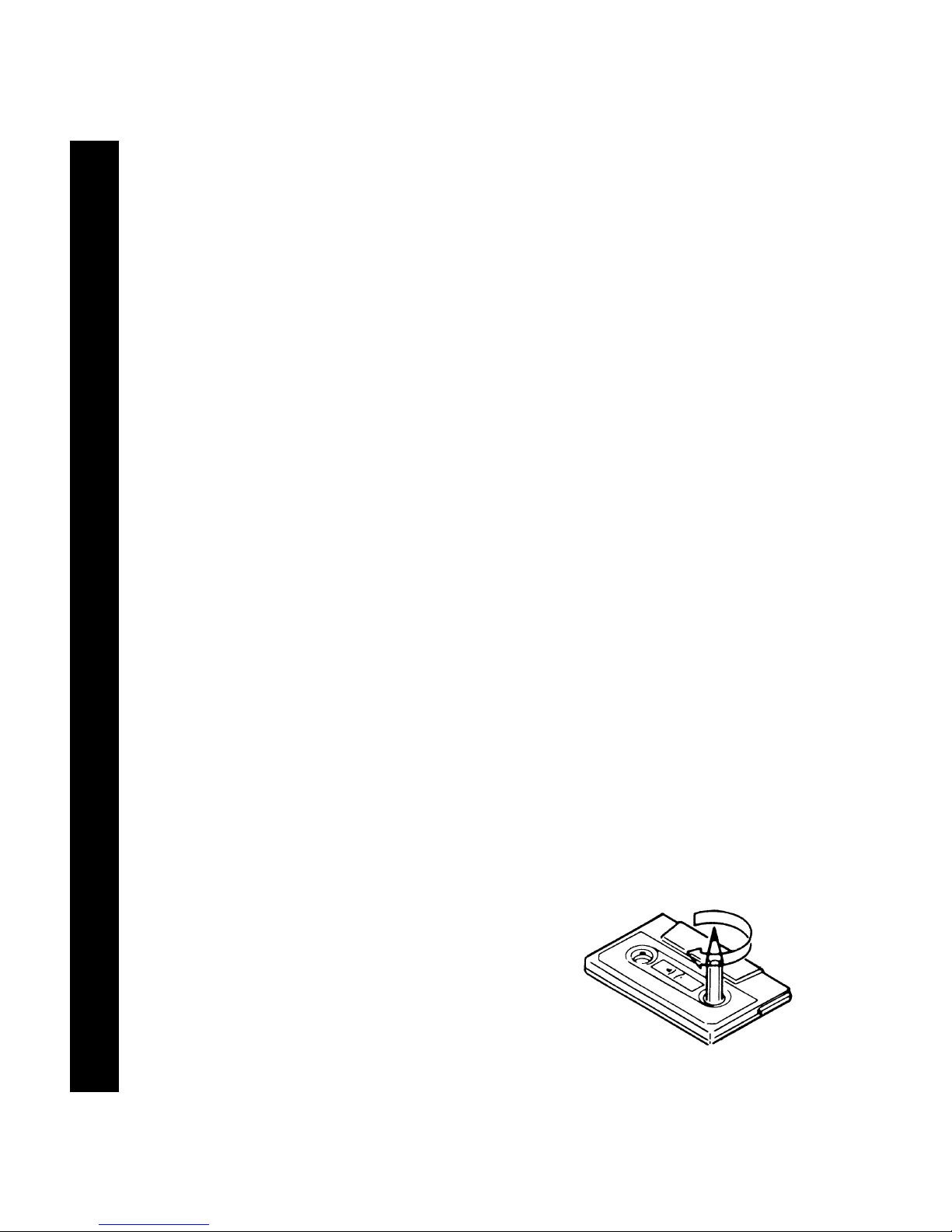
6. Before inserting a cassette in the player, check
that the tape istightly wound on thereels. Take
up any excess slack using a pencil to turn the
drive hub in the cassette (see diagram below).

12 MONTH LIMITED WARRANTY
AUDIOVOX CORPORATION (the Company)warrants to theoriginalretail purchaser ofthis product
that should this product or any part thereof, under normal use and conditions, be proven defective
in material or workmanship within 12 months from the date of original purchase, such defect(s) will
be repaired or replaced with new or reconditionedproduct (at the Company's option) without charge
for parts and repair labor.
To obtain repair or replacement within the terms of this Warranty, the product is to be delivered with
proof of warrantycoverage (e.g. dated bill ofsale), specification of defect(s),transportation prepaid,
to the warranty center at the address shown below.
This Warranty doesnotextend to theelimination of car staticor motor noise, tocorrection of antenna
problems, to costs incurred for installation, removal, or reinstallation of the product, or damage to
tapes, compact discs, speakers, accessories, or vehicle electrical systems.
This Warranty does not apply to any product or part thereof which, in the opinion of the Company,
has suffered or been damaged through alteration, improper installation, mishandling, misuse,
neglect, accident, or by removal or defacement of the factory serial number/bar code label(s). THE
EXTENT OF THE COMPANY'S LIABILITY UNDER THIS WARRANTY IS LIMITED TO THE
REPAIR OR REPLACEMENT PROVIDEDABOVEAND, IN NO EVENT,SHALLTHE COMPANY'S
LIABILITY EXCEED THE PURCHASE PRICE PAID BY PURCHASER FOR THE PRODUCT.
WARRANTY
WARRANTYWARRANTY
WARRANTYWARRANTY
This Warranty is in lieu of all other express warranties or liabilities. ANY IMPLIED WARRANTIES,
INCLUDING ANY IMPLIED WARRANTY OF MERCHANTABILITY, SHALL BE LIMITED TO THE
DURATION OF THIS WRITTENWARRANTY. ANY ACTION FOR BREACHOF ANY WARRANTY
HEREUNDER INCLUDING ANY IMPLIED WARRANTY OF MERCHANTABILITY MUST BE
BROUGHT WITHIN A PERIOD OF 30 MONTHS FROM DATE OF ORIGINALPURCHASE. IN NO
CASE SHALL THE COMPANY BE LIABLE FOR ANY CONSEQUENTIAL OR INCIDENTAL
DAMAGES FOR BREACH OF THIS OR ANY OTHER WARRANTY, EXPRESS OR IMPLIED,
WHATSOEVER. No person or representative isauthorized to assume for theCompany any liability
other than expressed herein in connection with the sale of this product.
Some states do not allow limitations on how long an implied warranty lasts or the exclusion or
limitation of incidental orconsequentialdamageso the above limitationsorexclusions may not apply
to you. This Warranty gives you specific legal rights and you may also have other rights which vary
from state to state.
U.S.A. : AUDIOVOX CORPORATION, 150 MARCUS BLVD., HAUPPAUGE, NEW YORK 11788 (800) 225-6074
CANADA: CALL 1-800-645-4994 FOR LOCATION OF WARRANTY STATION SERVING YOUR AREA
AUSTRALIA: AUDIOVOX PACIFIC PTY LTD., DOYLE AVENUE, UNANDERRA, NSW 2526 (042) 718-555
NEW ZEALAND: AUDIOVOX PACIFIC PTY LTD., UNIT B, 6 HENDERSON PLACE, PENROSE, AUCKLAND (09)645-720
Form No. 128-4270C1
88
8
88
 Loading...