

Page 1
>1UDIOrOX^
OWNER'S MANUAL
AND INSTALLATION GUIDE
AV-970
DIGITAL AM/FM/MPX RADIO WITH
STEREO CASSETTE PLAYER
Page 2

INDEX
How To Use This Manual......................................................................................Page 1
Kit Information.......................................................................................................Page 2
Universal and Import Car Installations
Chevrolet-Oldsmobile-Pontiac-Buick-GMC-Cadillac-Satum
Installations............................................................................................. Pages 5,6
Ford-Lincoln-Mercury Installations.....................................................................Pages 7,8
Chrysler-Dodge-Plymouth Installations
Radio Wiring............................................................................................................ Page 10
Speaker Wiring- 2 Speaker Systems..................................................................... Page 11
4 Speaker Systems.................................................................. Page 12
Operating Instructions..........................................................................................Pages 13,14
Specifications........................................................................................................Page 15
Troubleshooting.......................................................................................................Page 16
Care and Maintenance..........................................................................................Page 17
Warranty.................................................................................................................. Back Cover
Toll-Free Assistance
The installation and wiring connections for this unit are so simple, we doubt you'll need our
help, but, if you do, we're here to help you. Just call our toll-free telephone assistance line at
(800) 645- 7102 during days/hours shown.
...............................................................
...............................................................
Pages 3,4
Page 9
TIME ZONE
DAY
MON.-FRI.
SATURDAY
PACIFIC
5:30AM - 4PM
6AM - 2PM
MOUNTAIN
6:30AM - 5PM
7AM - 3PM
CENTRAL EASTERN
7:30AM - 6PM
SAM - 4PM
8:30AM - 7PM
9AM - 5PM
HELP!
1-800-645-7102
Monday - Friday 8:30am - 7:00pm Eastern
Saturday 9:00am - 5:00pm Eastern
HOW TO USE THIS MANUAL
1. Identify the make and year of the car in which you will be installing this sound system.
2. Refer to the Kit Listing and Kit Information sections on page 2 to determine if a kit is required.
3. If a kit is required, follow the directions in Kit Information section.
4. Follow the specific installation instructions for your particular make of car as listed in the index.
Page 3

KIT INFORMATION
1. The years shown in the Kit Listing below are approximate. Always check the application chart at your
retail store to find information on your specific make, model, and year of vehicle. If a kit is required, read
the description on the kit you intend to purchase to make sure it applies to your vehicle. If you have
any doubts or questions, call our toll-free “HELP" line.
2. The kits shown below are Audiovox kits. Your retailer may sell kits made by other manufacturers which
may also be usable to install this radio. Always check the kit application before purchasing it to make
sure it will work with your vehicle.
3. If you believe you need a kit but cannot find a retail store where it is available, call our toll-free "HELP"
line.
KIT LISTING
VEHICLE TYPE KIT REQUIREMENT/NOTES
Chevrolet-Oldsmobile-Buick-Pontiac-Cadillac-Saturn
1981 and Older............................................................................No Kit Required
1982 and Newer..........................................................................AX-93-FCGM
Chevrolet-GMC Full Size Vans
1987 and Older............................................................................No Kit Required
1988 and Newer
Chevrolet-GMC Full Size Pickups
1987 and Older
1988 and Newer
Chrysler-Dodge-Plymouth
U.S. Built 1974 and Newer..........................................................AX-93-FCGM
Imported ......................................................................................Refer to In-Store Chart
Ford-Lincoln-Mercury
1984 and Older............................................................................No Kit Required
1985 through 1990
1991 and Newer...........................................................................AX-88-SNP
AMC-Jeep-Eagle
1971 and Newer..........................................................................
.........................................................................
..........................................................................
.........................................................................
.................
.................................................. AX-93-FCGM
AX-88-CHV
No Kit Required
AX-88-CHT
No Kit Required
IMPORTCARS
Due to the wide variety of import cars and the different installations required, this manual does not show
specific installations in these vehicles. However, this sound system can be installed in many import cars
by following the "Universal Installation" section on pages 3 and 4. Check the application chart at your retail
store or call our toll-free "HELP" line for specific information on your particular car.
IMPORTS:
Acura-Audi-BMW-Daihatsu-Fiat-Honda-Hyundai
Mercedes-Peugeot-Porsche-Saab-Subaru
Volkswagen-Volvo-Yugo
Datsun-Nissan (Most Models)
1982 and Newer........................................................... Will Fit Most Years; Some Require AX-88-NAB Kit *
Mazda (Most Models)
1986 and Newer
Toyota (Most Models)
1982 and Newer...........................................................Will Fit Most Years; Some Require AX-88-TOY Kit *
For vehicles not listed or more specific information, refer to the in-store application chart or call our "HELP"
line.
...................................................
.......................................................
* Refer to In-Store Chart to determine if kit is required.
Will Fit Most Years; Some Require AX-88-SNP Kit *
Will Fit Most Years; Some Require AX-87-MAZ Kit *
Page 4
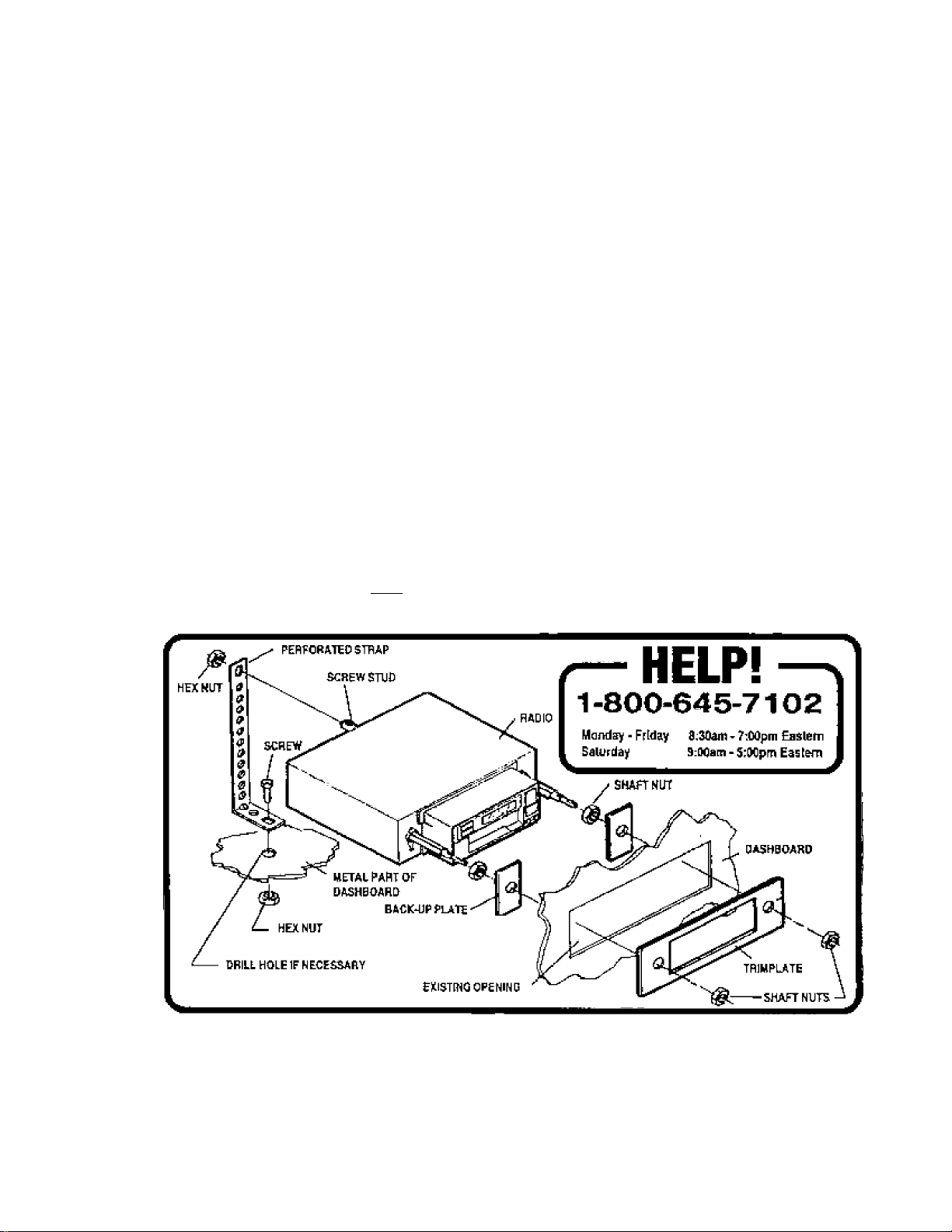
UNIVERSAL MSTALUTION FOR VEHICLES WITH AN EXISTIN6 RADIO QPENIN6
Thifs installation is designed for oars, tojclts, vans, and boats liiat have an existing radio opening. It can also be used
as an option on some of the vehicles listed as requiring Ihe AX-fiS-SNP kit. It wiil not work on all vehicies, but can be
used on most newer Fords and many imports.
1. Insped IlH Ejlistliig Rarfle Opening;
A. Use the tiirnplate suppiied with the radio to cover the existing opening. i1 it compieteiy covers Ibe opening, you
can install the radio as explained below. If it does not cover the opening, you wiil need an installation kit.
B, Check that there wiii be sufficient space behind the dashboard for the radio chassis,
2. Wlra the Raina to Hh VWilda's Wliliig:
A. In mast cases it is easier to wire the radio before mounting it. Place the radio near the dashboard so the wires
can be led through the opening.
B. Carefully foliow the (Vagrams on pages 10 and 11 or f 2 (depending on how many speakers you ana using) to
wire the radio, making certain all connections are secure and insulated with wire nuts or eiectrical tapeto insure
proper operation of the unit.
C After corrrpieting the wiring, turn the unit on to conlimn operation (ignition switch must be 'on'). If unit does not
operate, re-check ail wiring until probiem is corrected. Once proper operation is achieved, turn off unit arid
ignition switch, and proceed with Itnal mounting of the radio
3. MoHnHiig the Hailo:
A. Thread a shalt nut hall-way down each radio shaft.
Piace a metal back-up plate on each radio shaft against the shaft nut.
B.
Posilion the radio behind the dashboard opening so that the back-up piates are snug against the back of the
C.
opening. Adjust the shaft nuts behind the back-up piates so that the desired amount of radio extends through
the opening. If possible, the best appearance is usually achieved when there is enough of the radio extending
to be flush with the front ot the trimplate.
Place the trimplate over the front of the radio and secure it with a shaft nut on each radio shaft.
D.
Attach one end of the perforated support strap (supplied) to the screw stud on the radio using the hex nut
E.
provided. Fasten the other end of the perforated strap to a secure part of the dashboard either above or below
the radio using the screw and nut provided. Bend the strap to position it as necessary.
CAinjON: The rear ot the radio must be supported with the strap to prevent damage to the dashboard Irom the
weight ot the radio or improper operation of Ihe radio due to vibration.
F. Install knobs on radio shafts.
Page 5
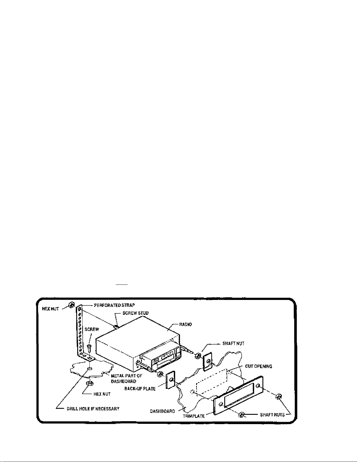
UNIVERSAL INSTALLATION FOR VEHICLES WITHOUT AH EXISTING RADIO OPENING
This instaHatbn is designed lor cars, iruchs, vans, and beats that da nol have an existing radio opening, it will require
cutting an opening in a surface of the vehiefe, so it is impertanit to mart! and rnoasure carefully.
1. lihrt Hi* MwtiHj V—:
A. Using the irtmplale supplied, verity that there will he sufficient space on the selected mounting surface.
B. Check that there will be sufficient space behind (he dashboard fer the radio chassis.
2. а)ЛШЛ»щИл40р9ЛЫ9:
A. Using the trimplate as a template, place it on Hie sefseted rnourtfirtg surface and mark the 2 shaft holes and
nosepiece opening that will need to be cut.
B. Carefulty cut the 3 holes using a driJI and keyhole saw as appropriate. File edges et the openings to remove
any burrs.
1. Wk« Ш Ы1« li th* V«fekl*4MrlBi;
A. In most cases H rs easier to wire Ihe radio before mounting it. Place the radio rrear the dashboard so the wires
Can be led through the opening.
B. Carefully folFow the diagrams on pages 10 and 11 or 13 {depending on how many speakers you are using) to
Wire the radio. maKing certain all connections are secure and insulated with wire nuts orelectrioai tape to insure
proper operation of the unit.
C. After completing the wiring, turn the unit on lo conliim operation (ignition switch must be *on*). if unit does not
operate, re-check ail wiring until problem is corrected. Once proper operation Is achieved, turn off unit and
ignition switch, and proceed with final mounting o1 the radio.
4. tin raOi:
A. Thread a shaft nut half-way down each radio shaft.
B. Place a melaJ back-up plate on each radio shaft against the shaft nut.
C. Position the radio behind Ihe dashboard opening sc that the back-up plates are snug against the back of the
opening. Adjust the shaft nuts behind the back-up plates so that the desired amount of radio extends through
the opening, ff possible, the best appearance is usually achieved when there is enough of the radio extending
to be flush with the front of the trimplate,
D. Place the trimplate over the front ot the radio and secure if with a shaft nut on each radio shaft
E. Attach one end of the perforated support strap (supplied) to the screw stud on the radie using the hex nut
provided. Fasten the other end of the perforated strap to a secure part of the dashboard either above or below
the radio using the screw and nut provided. Bend the strap to position it as necessary.
CAUTION: The rear of the radio must be supported with the strap to prevent darnage to the dashboard from the
weight of the radio or improper operation of the radio due to vibration.
F. install knobs on radio shafts.
Page 6
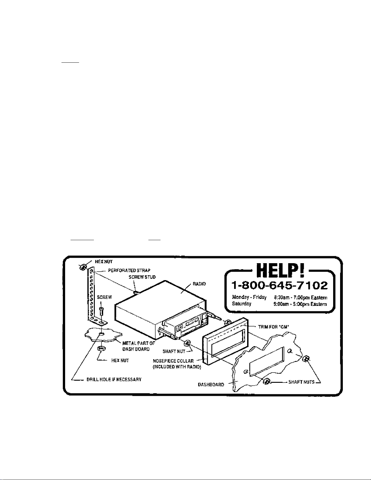
CHEVROL£r-OLDSMOBILE-BUICK-f4IHTIAC-GMC-CADIlUU; mSTAUATION
1981ANB OLDER
Important-This mstallation is design«! for "i981 and older U.S- made GM cars, trucks, and varts. For 1981 and newer
vehicles, an inslallalion kit may be required. See Kit Usting on Page 2 of this manual or refer to the In-store application
chart, ft a krt is not required, use Ihe fallowing Instructions.
1. !!■■■■• ExlStfug IUJIk
A. Remove radio knobs and shaft ntits behind the knobs.
B. Locate and remove support brace at back of radio.
C. Push radio back into dashboard to access the wiring and antenna cables plugged into the rear of the chassis.
D. Un-plug the wiring hamesa(es) and antenna cable and remove the radio.
2. Win fha In Radi«
A. In most cases It is easier to wire the radio before mounting it. Place Ihe radio near the dashboard so the wires
can be led through the opening.
B. Carefully lollcw the diagrams on pages Ю and 11 or (depending on how many speakers you are using) to
wire the radio, making certain all connections are secure and insulated with wire nuts or electrical tape to insure
proper operation of the uniL
C. After completing the wiring, lum the unit on to confirm operation (ignition switch must be 'оп*), if unit does not
operate, re-check all wiring until problem Is corrected. Once proper operation is achieved, turn off urrlt and
ignition switch, and proceed with final mounting of the radiO-
3. iBitalttaRnlMlK
A. Thread a shaft nul half-way down each radio shaft.
B. Trim the top edge off o1 the nosepiece collar at the 'CUT OFF FOR GM' mark and place the collar on radio
nosepiece.
C. Place the radio behind dashboard and through the radio opening. Adjust the position of the shaft nuts so that
the radio nosepiece and collar are flush against the back of the dashboard.
D. Secure the radio with a shah nul on each radio shaft.
E. Attach one end of the perforated support strap (supplied) to the screw stud on the radio using the hex nut
provided. Fasten the other end of the perforated strap to a secure part of the dashboard erther above or below
the radio using the screw and nut provided- Bernt the strap to position it as necessary.
CAUTION: The rear of the radio must be supported with the Strap to prevent damage to the dashboard from the
weight of the radio or Improper operatlorr of the radio due to vibration.
F. Install knobs on radio shahs.
Page 7

CHEVROLET-OLDSMOBIIE-BUICK-POIfTIAC-GMC-CADILLAC-SJmiRNmSTALUTION
1982 AND NEWER
|mppft»nt-Thls in$tallation is designed lor most 1982 and newer GM cars, trucKs, and vans where an Installatior kit
is required. See Kit Listing on Page 2 of this manual or refer lo the in-store application chart. If a kit is not required,
use the irislnjclions on Page 5.
1, !!■■■— Eairtim ItaJt«
A. F amove the existing dashboard trimpanel surrourkding the radio opening. This panel is usually secured by
screws and/or snap-in clips.
B. Remove the screws used to secure the radio to Ihe sub-dashboard.
C Pull the radio forward to access the wiring and antenna cables plugged into the rear of the chassis.
D. Un-plug the wiring hamessfes) and antenna cable and remove the radio.
i 2. mt>l(№«NHrlMi«
A. Follow the instructions included wHh the installation kil to attach the radio to the mounting plate supplied with
I the kit.
B. Place the radio near Ihe dashboard so the wires can be led through the opening and following the instructions
of Stepson Page 5. carefully wire the radio making certain all connections are secure and insulated and confirm
proper operation.
Q. Install the radio/lmountLng plate assembly to the sub-dashtxiard accoiiding to instructions of inslallaiion kit.
D. Attach one end of the perforated support strap (supplied) to the screw stud on Uie radio using the hex nut
provided. Fasten the other end ol the perforated strap to a secure part of the dashboard either above or below
the radio using the screw and nut provided. Bend Ihe strap lo position it as necessary.
CALfTlONt The rear oí the radio must be supported with the strap to prevent damage lo the dashboard from the
weight ol the radio or improper operation of the radio due to vibration.
E. Replace the dashboard trimpanel.
F. Install knobs on radio shafts.
wm
Page 8

PI
FORD-UHCOLN-lilERCURriNSTALLATfON - 1984AND0LDER
Importanl-This ingratiation is designed for 19S4 and okter U,S. nna<te Ford caig. trucks, and vans. For newer
vehicles, an inslailation kit may be required. See Kit Listing on Page 2 ot this manual or гЫег to the in-slore chart,
1. R«Mo« Existlag RadHr
A. Remove radio Knobs and shaft nuts behind the knobs,
B. Locate and remove support brace at back of radio.
C. Pushradiobackintodastiboardtoaccessihewiringandantennacabiespluggedintoltierearofthechassis
D- Un-piug the wiring harriess(es) and antenna oabie and remove the radio.
г. win tMiM hipa:
A. inmost cases ¡lis easier to wire the radio before mounting it. Race iher^Ldionearthedashboardsothewires
can be ied through the opening.
B. CarefLEily follow the diagrarns on pages 10 and 11 or 12 [depending on how many speakers you are using)
to wire the radio, making certain aii connections are secure and insulated with wire nuts or etectrical tape to
insure proper operation of the unit.
C. After compieting the wiring, turn the unit on to confirm operation [igrtition switch must be *on'). if unit does
not operate, re check ail wiring until problem is connected. Once proper operation is achieved, turn off unit
and ignition switch, and proceed with final mounting of the radio.
3. taltal tiHiHbll«;
A. Thread a shaft nut halfway down each radio shaft.
B. Place the nosepiece collar on the radio nosepiece.
C. Plaoetheradiobehinddashboardandthroughtheradioopening. Adjustthepositionoftheshaftnutssothal
the radio nosepiece and collar are flush against the back of the dashboard.
O. Secure the radio with a shaft nut on each radio shaft.
E. Attach one end of the perforated support strap (supplied] to the screw stud on the radio using the hex nut
provided. Fasten the other end of the perforated strap to a secure partofthedashboardeitheraboveorbeloiw
the radio using the screw and nut provided. Bend the strap to position it as necessary.
CiUBOtL-The rear of the radio must be supported with the strap to prevent damage to the dashboard from the
weight of the radio or improper operation of the radio due to vibration.
F. Install knobs on radio shafts.
Page 9

FOnD-LINCOLH-MEIICUIIYIIfSTALLATIDK - 1985 AND NEWER
ImPBftant'This instalfation is designed for mosl 1985 through 1990 U.S, made Ford oars, and vans and an
Installationkitisrequiredfofthesevebicles.SeeKiflistingon Page 2ofthismanLiaior refer to thein-Btoreappllcalion
chart. For 1991 and newer vehicles, Ihe radio can be installed as shown on Page Э of this manual or you can use
the AX-ee-SN P kit. instructions tor use of the AS-B8-SNP kitareindudedwiththekitandarenot shown in this marmaf.
1. RHsn Exlxtliig Паё1а:
A. Remove existing dashboard irimpanei surrounding the radio operring. This panel is usually secured by sore ws
and/or snap-in clips.
B. Remove the screws used to secure radio to the sub-dashboard.
C. Pull the radio forward to access the wiring and antenna cables plugged into the rear of the chassis.
D. Un-pfug the wiring hamess(es) and antenna cable and remove the radio.
2. hstillllH NmlMI«:
A. Follow the irrstmctions included with the installation kit to attach the radio to the mounting plate supplied with
the kit.
B. Place the radio rrear the dashboard so the wire can be led through the opening and following the Inslmclions
of Step 2 on Page 7, carefully wire the radio making certain ali connections are secure and insulated and
confirm proper operation.
C. Install the r^dio/mountlng plate assembly to the sub-dashboard according to instructions of installation kit.
D. Attach one end of Ihe perforated support strap (supplied) to the screw stud on the radio using the hex nut
provided. FastentheotherendoftheperForatedstraptoasecurepartofthedashboardeitheraboveorbelow
the radio usirtg the screw and nut provided. Bend Ihe strap lo position ft as necessary.
СА1ШШ1 The rear of the radio musí be supported with tbe strap to preveni damage to the dashboard from the
weight of the radio or improper operation of Ihe radio due to vibration.
E. Replace the dashboard trtmpanei.
F. Install knobs on radio shafts.
Page 10

GHinSLER-DODGE-PLTMOUTHIIISTAU.ATION
ALL U.S. MADE CARS, TRUCKS, AND VANS BUILT SINCE 1974
important-This fadio cannot be installed in any U.S. made Chrysler, Dodge, or Ptyrnouth vehicle without an
instaliation kit. Refer to Ihe Kit Listing on Page 2 lor the required kit. Compiete kit installation is explained in the
instructions included with the kit.
^. Натпв Extsting Radio:
A- Remove the existing dashboard trimpanei surrounding the radio opening. This panel is usually secured by
screws and/or snap-in clips,
B. Remove the two large screws used to secure radio to the sub-dashboard,
G. Pull Ihe radio forward to access the wiring and antenna cables plugged into the near of the chassis.
D. Un-plug the wiring hamessies) and antenna cable and remove the radio,
2. ■■■taJItfeelewfladli:
A. follow Ihe instructions included with the installation kit to attach the radio to the mourning plate supplied with
the kit.
B, Place the radio near ihe dashboard so the wires can be led through the opening and fallowing Ihe Instructions
of Step 2 on Page 3. carefully wire the radio making certain all connscliorys are secure ar>d insulated and
conlirm proper operation.
C- Install the radio/mounting plate assembly to the suhHdashboard according to instructions of instalEalion kit.
D. Attach one end of the perforated support strap (supplied) to the screw stud on the radio using the hex nut
provided. Fasten the olherend of the perforated strap to a secure partof the dashboard either above or below
the radio using the screw and nut provided. Bend the strap to position it ss necessary.
CAUTION: The rear of the radio must be supported with Ihe strap lo prevent damage to the dashboard from the
weight of the radio or improper operation of the radio due to vibration.
E. Replace the dashboard trimpanei.
F. Install knobs on radio shafts.
Page 11

RADIO WIRIHG
REFER TO PAGE 11 OR 12 FOR SPEAKER W3WNG
10
Page 12

SPEAKER WIRING - 2 SPEAKER SYSTEMS
REFER TO PAGE 10
FOR RADIO WIRING
NEVER GfWUND NEGATIVE SPEAKER LEADS TO CHASSIS GROUND
FAILURE TO WIRE EXACTLV AS SHOWN BELOW MAYCAUSEELECTFlJCAL DAMAGE TO THE FlADtO.
HELP!
1-800-645-7102
Monday - Friday B:30flni - 7:D0pm Easlem
Satjrday 9:(№ani - S:Mpm Eastern
WAflWIHGl
11
Page 13

SPEAKER WIRING ■ 4 SPEAKER SYSTEMS
REFERTO PAGEIO
FOR RADIO WIRING
NEVER QROUND NEGATIVE SPEAKER IE ADS TO CHASSIS OPOUND-
FAILURE TO WIPE EKACRY ASSHOWhB£LOWMA¥CAUS£aECTRICAL D AMAiGt TO TP£ ftAOlO.
mmm
HELP!
1-800-645-7102
Monday- Friday S:S0am-7:Wpni Easlem Selurday 9:Mam - 6:00pm Eastern
RADIO
SEE PAGEIO FOR RADIO WIRING
(BUCK WWHITE STRIPE,
OFIANSE wWHiTE STUlPE)
DRIVER'S SIDE
LEFT FRONT SPEAKER
©¥
SPLICE
N,:
!>=
©.
DRIVER'S SIDE
LEFT BEAR SPEAKER
WHITE
VIOLET
FASSEKQER'SSIDE
RIGHT FROWT SPEAKER
YELLOW
LIGHT GREEH
®.il n.0
PASSENGER'S SIDE
RIGHT REAR SPEAKER
I©
SPLICE
12
Page 14

13
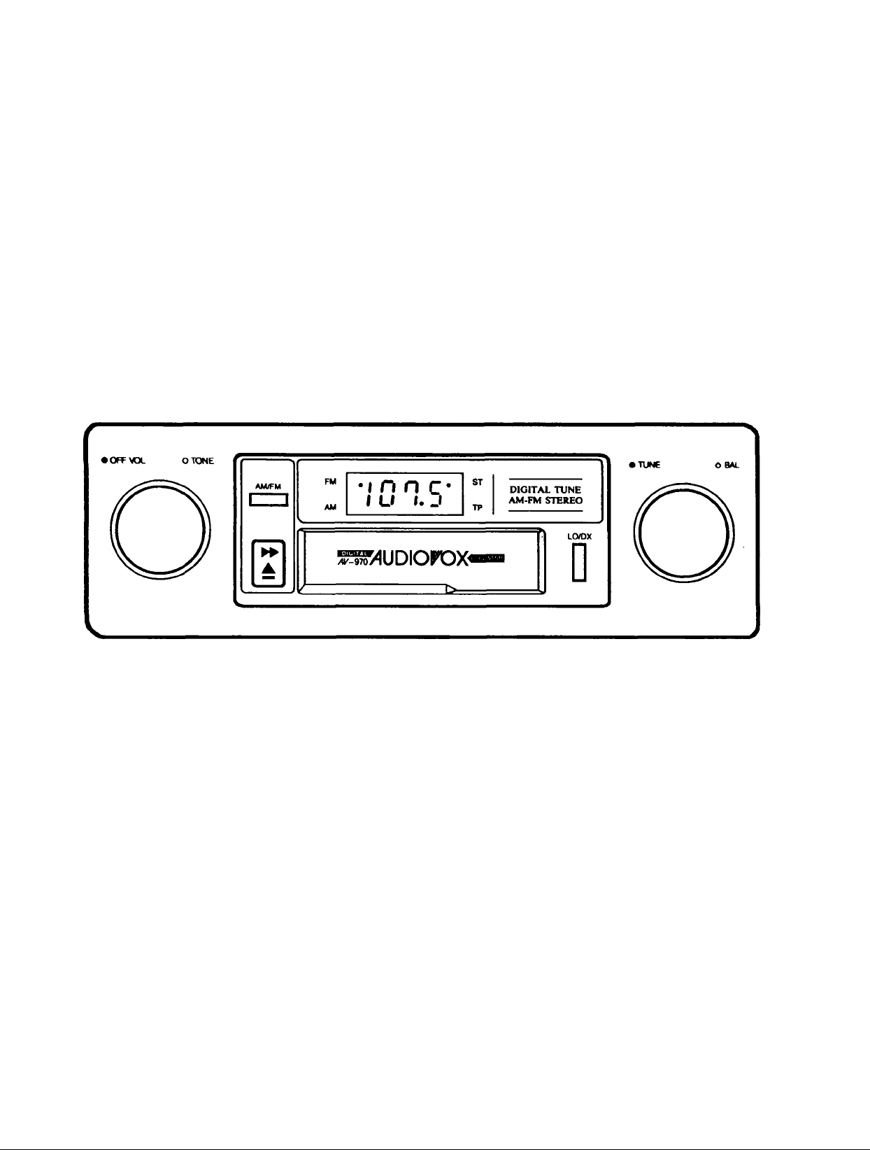
OPERATING INSTRUCTIONS
0 ON-OFF SWITCH/VOLUME CONTROL
Turn this knob to the right to turn the unit on.
Continue rotation untii the desired volume
ievef is obtained.
0 LEFT/RIGHT BALANCE CONTROL
Turn this knob to the left or right to obtain the
desired balance between ieft and right speak
ers,
0 TONE CONTROL
Turn this knob either to the left or right to
obtain the desired tone response. Turn it to
the right to increase the treble or to the left to
increase the bass.
0 AM/FM BAND SELECTOR
Each time this button is pressed, the radio
band changes. According to your selection,
the selected radio band indicator appears on
the display panel,
0 LOCAL-DISTANT SWITCH
This two position switch is incorporated to allow
maximum reception in both weak and strong
FM signal areas. When tuned to a weak
(distant) station, push the switch in. This will
allow maximum signal to the receiver. When In
an extremely strong signal area (local), release
the switch. This will eiiminate all weak signals
and suppress overly strong signals so as to
avoid overloading the receiver input. When
moving out of a strong signal area, return the
switch to the “distant" position.
Note: The Locaf-Distant switch only affects FM
signals.
Page 15

(D MANUAL TUNING CONTROL
Turn the knob either to the left or the right to
select a radio station.
© ANTENNA TRIMMER
It is very important to adjust the ANTENNA
TRIMMER for optimum AM reception. The an
tenna trimmer is located at the back in the tape
slot. Tune in a weak station around 1400 KHz
and adjust the trimmer with a small screwdriver
for maximum output.
Note: Antenna trimmer is for AM band only and
has no effect on FM band.
® DISPLAY PANEL
Displays frequency as well as indicators for
AM, FM, stereo reception (ST) and tape player
operation (TP).
(© CASSETTE SLOT
Hold a cassette with the exposed tape edge to
the right, then insert into the cassette slot.
Depress fully until the cassette is engaged and
begins playing. When the cassette reaches the
end of play, the unit will automatically change
over to radio operation.
Note: Observe cassette operation cautions in
Care and Maintenance section of this manual.
® FAST-FORWARD/EJECT BUTTON
This button performs two functions. To eject a
cassette, simply depress this button fully then
release. The cassette will eject and radio
operation will resume. To fast-forward the
tape, depress the button half-way in to the
locked position. To stop fast-forward and re
sume normal tape playback, depress the but
ton slightly and release. Do not press fully in or
the cassette will be ejected.
14»
Page 16

SPECIFICATIONS
Size;
Operating Voltage:
Output Power:
Output Wiring:
Output Impedance:
Tuning Range:
Sensitivity:
FM Stereo Separation: 30 dB
Tape Frequency Response: 50-10,000 Hz.
7"W X 2"H X 5“D
178mm X 50mm x 125mm
12 volts DC, negative ground
14 watts maximum
( 7 watts X 2 channels)
Common-ground type designed for 2 speaker use.
May also be used with 4 speakers.
Compatible with 4-8 ohm speakers
AM: 530-1,620 KHz.
FM: 87.5-107.9 MHz.
AM: 15 uv.
FM: 2.5 uv.
15
Tape S/N Ratio: 50 dB
Wow & Flutter: 0.25% WRMS
Specifications are subject to change without notice.
Page 17

TROUBLESHOOTING
^ """
PROBLEM
Unit completely inoperative no lights,
no sound
Unit v»iill not keep time or Radio
station memory _
Noise on tx»th radio and tape
Noise on radio only
Poor FM reception and almost no
AM reception
PROBABLE CAUSE
Incorrect power connection .
Blown fuse
Incorrect power connection
Blown fuse
Poor ground
Dirty or corroded battery posts
If problem also existed with previous
radio you removed
Antenna
Antenna
CHECK FOLLOWING
Orange/Whitestiipewireto+12V ACC.
and Green/White stripe wire to+12V
battery
Check fuses in wires listed above and
check car fuse block
Green/White Stripe wire is not con
nected to a "live" +12V battery source
Check fuse in Green/White stripe wire
and at car's fuse block
Check Black/White stripe wire for
proper grounding
Clean and tighten connection
Consult your local garage mechanic-
car may need tune-up or noise filter
Check that antenna base is grourrded.
Test with antenna disconnected. If
noise goes away, replace antenna
Replace antenna and antenna cable
Poor FM reception and Good AM
reception
No sound on one speaker
(tK>th radio and tape)
Poor sound on tape only (after one
month or more of tape usage)
Poor sound-new unit
Wiring
FM Local-Distant switch
Speaker
Radio Operation
Dirty tape mechanism
For radios with 40 watts or more
output power
For all radios
Check if unit has a Local-DisUtnt switch
and set to "Distant* position
Check speaker wiring
Test with good speaker
Check baleince and fader controls
Clean tape head and mechanism
Check rating of speakers for sufficient
power capacity
Check that speakers are in good
•
condition
Check that Violet and Green speaker
wires are not grounded
Check speaker wiring
16
Page 18

CARE AND MAINTENANCE
The radio portion of yoor new sound system does not require any rnaintenance. We recommend you keep
this manual for general reference of the many features found in this unit.
As with any cassette piayer, the cassette section of this sound system does require a minimum of
mairrtenance to keep it in good working cor>d(iim. The following simpie care and maintenance suggestions
should be followed to prevent matfunclions of the cassette system.
Cassette Carr:
1. Purchase a cassette cleaning kit from your iocai retail store. Use it! At least every 20 (o 30 hours
of operation you nuist dean the cassette mechanism. A dirty cassette player wiii have a poor sound.
2. Do not use cassettes that exceed 45 minutes of piay on each side.
3. Do not insert a cassette that appears to be broker, twisted or dirty or with ioose or tom labels on it.
4. Always keep your cassettes away from direct sunlight or exposure to sub-freezing conditions. If a
cassette is cold, allow it to warm up before use.
5. Do not keep a cassette in the player when not in use,
e. Before inserting a cassette in the player, check that the tape is tightly wound on the reels. Take up
any excess slack using a pencil to turn the drive hub in the cassette (see diagram below).
17
Page 19

12 MONTH LIMITED WARRANTY
Applies to In-dash radios, radio/tape player and radio/CD player combinations, and CD Changers.
AUDIOVOX CORPORATION (the Company) warrants to the original retail purchaser of this product that should this
product or any part thereof, under normal use and conditions, be proven defective in material or workmanship within
12 months from the date of original purchase, such defect(s) will be repaired or replaced with new or reconditioned
product (at the Company's option) without charge for parts and repair labor.
To obtain repair or replacement within the terms of this Warranty, the product is to be delivered with proof of warranty
coverage (e.g. dated bill of sale), specification of defect(s), transportation prepaid, to an approved warranty station.
For the location of the nearest warranty station to you, call toll-free to our control office:
IN U.S.A. (800) 243-1311
IN CANADA (800) 461-1772
This Warranty does not extend to the elimination of car static or motor noise, to correction of antenna problems, to
costs incurred for installation, removal, or reinstallation of the product, ordamage to tapes, compact discs, speakers,
accessories, or vehicle electrical systems.
This Warranty does not apply to any product or part thereof which, in the opinion of the Company, has suffered or
been damaged through alteration, improper installation, mishandling, misuse, neglect, accident, or by removal or
defacement of the factory serial number/bar code label(s). THE EXTENT OF THE COMPANY'S LIABILITY UNDER
THIS WARRANTY IS LIMITED TO THE REPAIR OR REPLACEMENT PROVIDED ABOVE AND, IN NO EVENT,
SHALL THE COMPANY'S LIABILITY EXCEED THE PURCHASE PRICE PAID BY PURCHASER FOR THE
PRODUCT.
This Warranty is in lieu of all other express warranties or liabilities. ANY IMPLIED WARRANTIES, INCLUDING ANY
IMPLIED WARRANTY OF MERCHANTABILITY, SHALL BE LIMITED TO THE DURATION OF THIS WRITTEN
WARRANTY. ANY ACTION FOR BREACH OF ANY WARRANTY HEREUNDER INCLUDING ANY IMPLIED
WARRANTY OF MERCHANTABILITY MUST BE BROUGHT WITHIN A PERIOD OF 30 MONTHS FROM DATE
OF ORIGINAL PURCHASE. IN NO CASE SHALL THE COMPANY BE LIABLE FOR ANY CONSEQUENTIAL OR
INCIDENTAL DAMAGES FOR BREACH OF THIS OR ANY OTHER WARRANTY, EXPRESS OR IMPLIED,
WHATSOEVER. No person or representative is authorized to assume for the Company any liability other than
expressed herein in connection with the sale of this product.
Some states do not allow limitations on how long an implied warranty lasts or the exclusion or limitation of incidental
or consequential damage so the above limitations or exclusions may not apply to you. This Warranty gives you
specific legal rights and you may also have other rights which vary from state to state.
U.S.A. : AUDIOVOX CORPORATION, 150 MARCUS BLVD., HAUPPAUGE, NEW YORK 11788 • (800)243-1311
CANADA: AUDIOVOX CANADA LTD., MISSISSAUGA, ONTARIO • (800)461-1772
AUSTRALIA: AUDIOVOX PACIFIC PTY LTD., DOYLE AVENUE, UNANDERRA, NSW 2526 • (042)718-555
NEW ZEALAND: AUDIOVOX PACIFIC PTY LTD., UNIT B, 6 HENDERSON PLACE, PENROSE, AUCKLAND«(09) 645-720
L___________________________________________________________________________________
_____________________ _________________
Form No. 128.4I23C ^
AJDKWOX'
1995 Audiovox Corporation • 150 Marcus Blvd • Hauppauge, NY 11788
Printed in China
Form No. 128-4421C
 Loading...