

Page 1
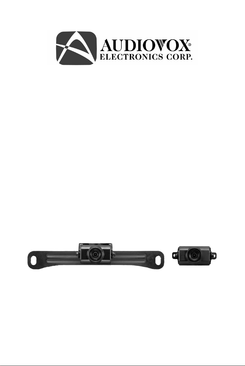
Model: ACA200W
Wired License Plate / Rear Mounted
Camera
Cámara de Montaje Posterior / Patente
Cableada
Installation Manual / Manual de Instalación
Page 2

Features
• High Resolution, ¼ inch CMOS Color Camera
• Compact Zinc Alloy Die Cast Body
• Waterproof Housing
• 130 Degree Wide View Angle
• Selectable Image: Normal/Reverse
• Camera Mounts Behind License Plate – Does Not Obstruct Plate
• Adjustable Camera Angle
Características
• Alta Resolución, Cámara Color CMOS de 1/4 de pulgada
• Cuerpo Moldeado en Aleación de Zinc Compacto
• Alojamiento a Prueba de Agua
• Ángulo de Visión Ancho de 130 Grados
• Imagen Seleccionable: Normal/Reversa
• La Cámara se Monta Detrás de la Patente – No Obstruye su Visión
• Ángulo de Cámara Ajustable
2
Page 3

Table of Contents
Warnings......................................................................................4
Product Description .....................................................................5
Packing List .................................................................................5
Camera Installation ...................................................................... 6
Camera Wiring Diagram..............................................................9
Specifications ............................................................................10
Troubleshooting .........................................................................10
Warranty ....................................................................................18
Tabla de contenidos
Cuidados ....................................................................................11
Descripción del Producto...........................................................12
Lista de lo Empaquetado............................................................ 12
Instalación de la Cámara............................................................13
Diagrama de Cableado de la Cámara.........................................16
Especificaciones ........................................................................17
Solución de Problemas............................................................... 17
Garantía......................................................................................19
3
Page 4

Warnings
The product is intended to assist in safe driving and to allow the driver to
have a broader rear view while the vehicle is in reverse. You, as the
driver, are solely responsible for the safe operation of your vehicle and
the safety of your passengers according to local traffic regulations. Do not
use any features of this system to the extent it distracts you from safe
driving. Your first priority while driving should always be the safe
operation of your vehicle. Audiovox Electronics Corporation cannot
accept any responsibility whatsoever for accidents resulting from failure
to observe these precautions or safety instructions.
1. This product utilizes high voltage. Any unauthorized modifications or
damage to the product may result in electrical shock. Handle all
components with care. Inspect regularly for damage to components
and cabling.
2. You are responsible for ensuring that the installation of this product
does not void or affect the vehicle manufacturer’s warranty.
Audiovox Electronics Corporation or its subsidiaries are not liable in
full or in part for improper installation resulting in loss or damage to
your property, or for voiding all or part of the vehicle manufacturer’s
warranty.
3. Do not apply excessive force to any of the components contained
within this kit. Excessive force used before, during or after
installation that results in a damaged or non-functional part will void
all warranties.
4. Please follow the procedures in this installation manual. Improper
installation or modification of this product will void all warranties.
4
Page 5

Product Description
This revolutionary camera design integrates a backup camera with your
vehicle’s rear license plate without covering the license plate. The camera
is easy to mount on your car, truck, or van with the bracket being hidden
by your license plate. We have also included a surface mount bracket to
help with other installation methods.
This Wired Camera is compatible with most monitors/TFT screens and
can be connected using a standard RCA connector.
Packing List
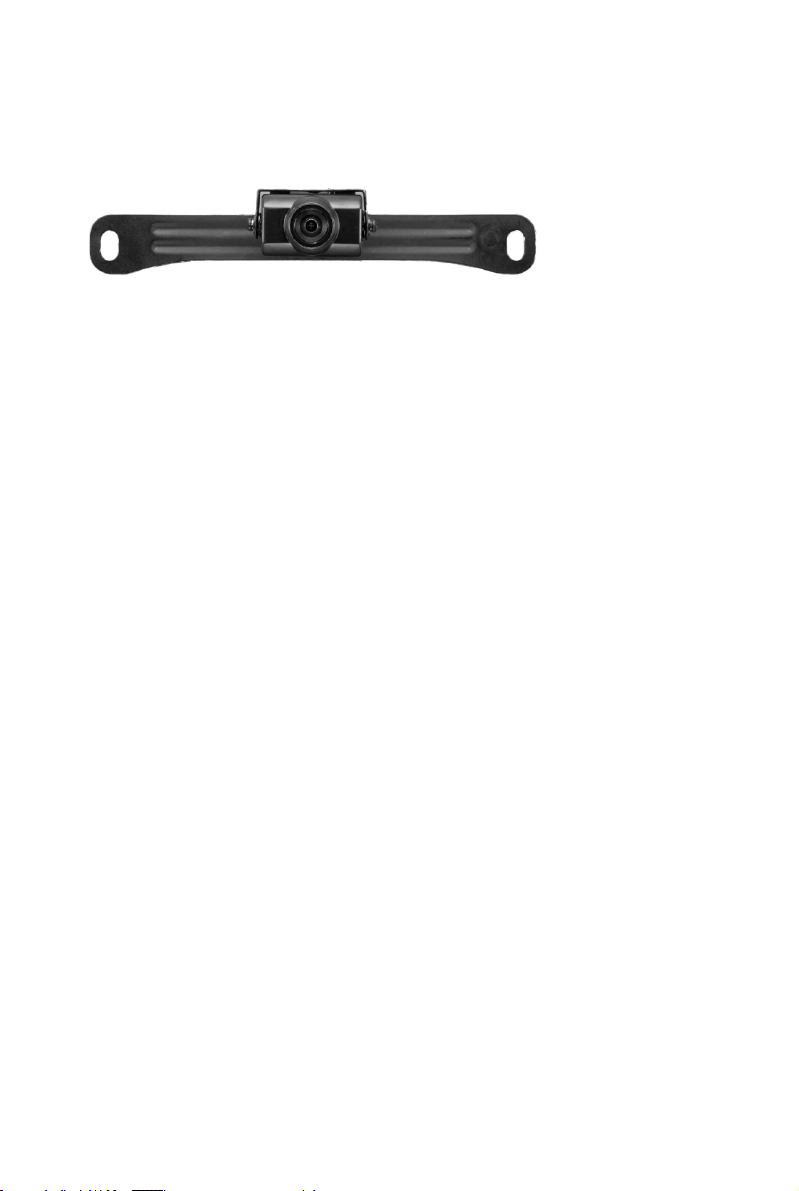
• CMOS Camera with License Plate Bracket – 1 qty Part # 30912040
• Surface Mounted Bracket – 1 qty Part # 30912270
• Hardware Package – 1 qty Part # 30912010
• RCA Video Extension Cable – 1 qty Part # 30912280
• Owner’s Manual – 1 qty Part # 30912020
5
Page 6
Camera Installation
License Plate Mounting Instructions
1. Remove the rear license plate.
2. Examine the vehicle to determine the best way to run the power wires
to the reverse lights and the extension cable through the car.
3. The Camera can be mounted above or below the plate. (For surface
mounting with the included bracket, see the next section.) Determine
the mounting location that best suits your needs. Be sure to verify that
your installation plan complies with local laws and requirements.
Most states require that the state name, registration stickers, and
license number are not obstructed in any way.
4. Place the camera bracket behind the license plate and line up the
holes. Fasten the camera mounting bracket and the license plate to the
vehicle using the anti-theft screws provided. After installation of
screws with the tool provided, place the tool in the glove
compartment or other safe place for future use.
NOTE: If you decide to mount the camera at the bottom of the license
plate, you must first remove the two screws that hold the camera to the
bracket and flip the camera over so the picture will not be displayed up
side down.
6
Page 7

Surface Mounting Instructions
1. Find a suitable location on the vehicle where the bracket will not
interfere with any equipment or doors, or block the line of sight.
Verify that the planned mounting location is accessible from behind
and that you have access to route the wiring inside the vehicle. Be
sure that the mounting screws will not hit any wires or equipment
inside the vehicle.
2. Attach the surface mounting bracket to the vehicle with the hardware
included.
3. Route the camera wiring into the vehicle. The wire can be run through
an existing grommet, behind a tail lamp, under the trunk molding, or
if necessary, through a 5/8 inch hole drilled near the vehicle’s rear
license plate. When choosing a wiring path, make sure the cable
will not be damaged or pinched, as this may cause a short circuit
that is not covered by the warranty. If drilling a hole, perform the
following steps:
a) Acquire a 5/8 inch drill bit, rust preventive, and a 5/8 inch
rubber grommet, all of which can be purchased at a hardware
store.
b) Check behind the intended drilling location before drilling to
verify that no wires or mechanisms can interfere with or be
damaged during drilling.
c) Check for interference with license plate lights and the hatch
release switch and/or mechanism.
d) Drill a 5/8 inch hole at the selected location.
e) Coat the edge of the hole with rust preventative.
f) Route the camera cable through the grommet and then through
the hole.
g) Insert the grommet in the hole to keep water from entering the
vehicle.
4. Remove the camera from the license plate bracket and attach it to the
surface mount bracket on the vehicle.
7
Page 8

Wiring the Camera to the Vehicle’s Reverse Lamp
1. Locate the reverse lamp in the tail light assembly.
2. Using the tap connector supplied, perform the following steps:
a) Place the un-stripped positive lead from the tail lamp in the run
channel, which runs completely through the connector.
b) Insert the un-stripped red power wire from the camera
completely into the other channel in the connector.
c) Make the connection between the wires by crimping down the
metal connector with a pair of pliers, making sure the metal is
flush with the plastic insulator.
d) Close the top plastic hinged cover until latched.
3. Attach the black wire to the ground (negative).
4. Repeat the above steps for the red wire.
8
Page 9

Connecting the Video Signal
1. Connect the included video extension cable to the Yellow RCA jack
on the camera harness.
2. Run the extension cable to the monitor and connect to the Video
input.
Reverse/Normal Image Adjustment
The camera comes standard with a reversed image, designed for mounting
at the rear of the vehicle. If you need to change to a forward or normal
image view, clip the blue jumper wire loop on the wiring cable (labeled
“Mirror Selection” below) to change the camera image to normal. Secure
the clipped wires with electrical tape. To change back to reverse image
view, reconnect the blue wires and secure with electrical tape.
Camera Wiring
9
Page 10

Specifications
1. Voltage: DC12V
2. Current: 50 mA
3. Signal System: NTSC
4. Image Sensor: ¼” CMOS Sensor
5. Horizontal Resolution: 480 lines
6. Viewing Angle: 130 degrees
7. Minimum Illumination: 0.3Lux
8. Image Display: Selectable Normal/Reverse Image
9. Wireless Transmission Operating Frequency: 2.4GHz
10. Adjustable Viewing Angle
11. Dimensions:
• Camera: 45mm W
• License Plate Bracket: 196mm W x 36mm H
Troubleshooting
Symptom Solution
No video signal appears while
reversing the vehicle
Video image is not sharp enough Clean the camera lens.
12. Check the rear view camera
lens and clean if needed.
13. Check the rear view camera
wiring connection and RCA
connection.
14. Check the fuse at the camera –
if blown replace only with a 1
amp fuse
15. Check the connections and
power at the monitor.
10
Page 11

Cuidados
Este producto pretende asistir en un manejo seguro permitiéndole tener
una visión posterior más amplia mientras el vehículo está en reversa.
Usted, como el conductor, es el único responsable por una operación
segura de su vehículo y por la seguridad de sus pasajeros, de acuerdo a la
regulación de tráfico de su localidad. No use ninguna función de este
sistema al punto de distraerlo de un manejo seguro. Su primera prioridad
mientras maneja siempre debería ser la operación segura de su vehículo.
Audiovox Electronics Corporation no puede aceptar ninguna
responsabilidad de ningún tipo por accidentes provocados por fallas al
seguir estas instrucciones de precaución y seguridad.
1. Este producto utiliza alto voltaje. Cualquier modificación o daño no
autorizado en este producto puede provocar choque eléctrico. Maneje
todos los componentes con cuidado. Inspeccione regularmente si hay
daños en componentes o cableados.
2. Usted es responsable de asegurar que la instalación de este producto
no invalida o afecta la garantía del fabricante del vehículo. Audiovox
Electronics Corporation o sus subsidiarias no son total ni
parcialmente responsables de instalaciones inadecuadas que
provoquen pérdida o daño a su propiedad, o de invalidar toda o parte
de la garantía del fabricante de su vehículo.
3. No aplique fuerza excesiva a ninguno de los componentes contenidos
dentro de éste equipo. Usar fuerza excesiva antes, durante o luego de
la instalación que resulte en daños o fallas en el funcionamiento de las
partes puede invalidar todas las garantías.
4. Por favor, siga los procedimientos en el manual de instalación. La
instalación o modificación inadecuada de este producto invalidará
todas las garantías.
11
Page 12

Descripción del Producto
Este revolucionario diseño integra una cámara posterior con la patente
posterior de su vehículo sin cubrirla. La cámara es fácil de montar en su
automóvil, camión o van con el soporte escondido por la patente. Hemos
incluido también un soporte de montaje superficial para facilitar otros
métodos de instalación.
Esta Cámara Cableada es compatible con la mayoría de los
monitores/pantallas TFT y se pueden conectar usando un conector RCA
estándar.
Lista de lo Empaquetado
• 1 Cámara CMOS con Soporte para Patente – Parte Nº 30912040
• 1 Soporte Montado en Superficie – Parte Nº 30912270
• 1 Paquete de Herramientas – Parte Nº 30912010
• 1 Cable de Extensión de Video RCA – Parte Nº 30912280
• 1 Manual del Propietario – Parte Nº 30912020
12
Page 13

Instalación de la Cámara
Instrucciones de Montaje de la Patente
1. Quite la patente posterior.
2. Examine el vehículo para determinar la mejor forma de colocar los
cables de energía hasta las luces de reversa y el cable de extensión por
el automóvil.
3. La Cámara se puede montar sobre o debajo de la patente. (Para
montaje en superficie con el soporte incluido, vea la siguiente
sección.) Determine la ubicación de montaje que mejor le convenga.
Asegúrese de verificar que su plan de instalación cumple con las leyes
y normativas locales. La mayoría de los estados exige que el nombre
del estado, adhesivos de registración y número de patente no estén
obstruidos de ninguna forma.
4. Coloque el soporte de la cámara detrás de la patente y alinee los
agujeros. Ajuste el soporte de montaje de la cámara y la patente al
vehículo usando los tornillos antirrobo provistos. Luego de la
instalación de los tornillos con la herramienta provista, coloque la
herramienta en la guantera u otro lugar seguro para su uso futuro.
NOTA: Si usted decide montar la cámara debajo de la patente, primero
debe quitar los dos tornillos que sostienen la cámara al soporte y gire la
cámara de forma tal que la imagen no se muestre al revés.
13
Page 14

Instrucciones de Montaje Superficial
1. Encuentre una ubicación en el vehículo donde el soporte no interfiera
con ningún equipo o puerta, o bloquee la visión. Verifique que la
ubicación de montaje elegida sea accesible desde atrás y que tenga
acceso para pasar el cable hacia adentro del vehículo. Asegúrese que
los tornillos de montaje no golpeen ningún cable o equipo adentro del
vehículo.
2. Adjunte el soporte de montaje superficial al vehículo con las
herramientas incluidas.
3. Pase el cableado de la cámara hacia adentro del vehículo. El cable se
puede pasar por un reborde existente, detrás de la lámpara, debajo de
la estructura del camión, o si es necesario, por un agujero de 5/8
pulgadas taladrado cerca de la patente posterior del vehículo. Cuando
elija un recorrido para el cableado, asegúrese que el cable no esté
dañado o pinchado, pues esto puede causar un cortocircuito que no
está cubierto por la garantía. Si taladra un agujero, realice los
siguientes pasos:
a) Busque una punta de taladro de 5/8 de pulgadas, antióxido, y un
reborde de goma de 5/8 de pulgadas, los cuales se pueden
comprar en una ferretería.
b) Antes de taladrar, verifique detrás de la ubicación donde desea
agujerear que no hayan cables o mecanismos que puedan
interferir o que puedan ser dañados.
c) Verifique interferencias con las luces de la patente, la llave del
baúl y/o sus mecanismos.
d) Taladre un agujero de 5/8 de pulgadas en la ubicación
seleccionada.
e) Cubra los bordes del agujero con antióxido.
f) Coloque el cable de la cámara por el reborde y luego por el
agujero.
g) Inserte un reborde en el agujero para evitar que entre agua al
vehículo.
14
Page 15

4. Quite la cámara del soporte de patente y adhiérala al soporte
superficial del vehículo.
Cableando la Cámara a la Lámpara de Reversa
1. Localice la lámpara de reversa en el ensamblaje de luces de cola.
2. Usando un conector de llave provisto, realice los siguientes pasos:
a) Coloque la punta positiva pelada de la cola de la lámpara en el
canal del cableo, que corra completamente hasta el conector.
b) Inserte el cable de energía rojo pelado desde la cámara
completamente hacia el otro canal en el conector.
c) Realice la conexión entre los cables crimpeando el conector de
metal con un alicate, asegurándose que el metal esté a la altura
del aislante plástico.
d) Cierre la tapa plástica de la bisagra superior hasta que suene.
3. Adhiera el cable negro a tierra (negativo).
4. Repita los pasos de arriba para el cable rojo.
15
Page 16

Conectando la Señal de Video
1. Conecte el cable de extensión de video incluido, a la toma RCA
amarilla en el arnés de la cámara.
2. Coloque el cable de extensión al monitor y conéctelo a la entrada de
Video.
Ajuste de Imagen Reverso/Normal
La cámara viene estándar con una imagen invertida, diseñada para
montarla en la parte posterior del vehículo. Si usted necesita cambiar a
una imagen con una vista hacia adelante o normal, sujete el bucle de cable
puente azul al cable (etiquetado como "Mirror Selection”) para cambiar
la imagen a normal. Asegure lo cables sujetados con cinta aisladora.
Para volver a una imagen de reversa, reconecte los cables azules y
asegure con cinta aisladora.
Cableado de la Cámara
16
Page 17

Especificaciones
1. Voltaje: DC12V
2. Corriente: 50 mA
3. Sistema de Señal: NTSC
4. Sensor de Imagen: Sensor CMOS de ¼”
5. Resolución Horizontal: 480 líneas
6. Ángulo de Visión: 130 grados
7. Iluminación Mínima: 0.3Lux
8. Imagen en Pantalla: Seleccionable Normal o Reversa
9. Frecuencia de Operación de Transmisión Inalámbrica: 2,4GHz
10. Ángulo de Visión Ajustable
11. Dimensiones :
• Cámara: 45mm W
• Soporte de Patente: 196mm Ancho x 36mm Alto
Solución de Problemas
Síntoma Solución
No hay señal
de video
mientras el
vehículo está
en reversa
La imagen de
video no es
nítida
1. 1. Verifique los lentes de la cámara posterior y
limpie
si es necesario.
2. 2. Verifique la conexión de cabe de la cámara
posterior y la conexión RCA.
3. Verifique el fusible de la cámara, si está quemado
reemplace solamente con un fusible de 1 ampere
4. Verifique las conexiones y energía en el monitor.
Limpie los lentes de la cámara.
17
Page 18

18
Page 19

19
Page 20

© 2008 Audiovox Electronics Corp., 150 Marcus Blvd., Hauppauge, N.Y. 11788
20
 Loading...