

Page 1

Model AA-9347
REMOTE CONTROL AUTO SECURITY SYSTEM
WITH VOICE WARNING SYSTEM & BUILT IN 2 - STAGE SHOCK SENSOR
INSTALLATION GUIDE& OWNER’S MANUAL
SYSTÈME DE SÉCURITÉ À TÉLÉCOMMANDE POUR VÉHICULES,
AVEC AVERTISSEUR À SYNTHÈSE VOCALE ET
DÉTECTEUR DE VIBRATIONS INCORPORÉ À 2 NIVEAUX
GUIDEPOUR L’INSTALLATION ETMANUELDE L’UTILISATEUR
SISTEMA DE SEGURIDAD PARA AUTOMOVILES A CONTROL REMOTO, CON SISTEMA
DE ALARMA POR VOZ Y DETECTOR DE CHOQUE INCORPORADO DE 2 ETAPAS
GUIA DE INSTALACION Y MANUAL DEL PROPIETARIO
Page 2

INTRODUCTION
Your new AA -9347 Automotive Security System has been designed with many
advancedfeaturesthatwillhelptoensurethesafetyofyourvehicleandit’scontents.
Taking a few moments to read this manual will provide you with important
information required to take advantage of the system’s full potential.
Performing the installation procedure in the order that the steps are outlined in this
manualshould provide you with a quick and trouble freeinstallation, and remember,
if you havequestions at any time during the installation, call 1 - 800- 225 - 6074 for
the AUDIOVOX INSTALLATION HOT LINE.
TABLE OF CONTENTS
Mounting Components
MountingtheSirenControlModule........................................................1
-Mounting the Hood and Trunk Pin Switches
Mounting the Dash L.E.D. Indicator ..................................................2
-Mounting the Valet Toggle Switch
-Mounting the Relay
Wiring the System
Routing the Wiring Harness .............................................................3
-Connecting the RED wire
-Connecting the BLACK wire
Connecting the WHITE wire ..............................................................4
-Connecting the BROWN wire
-Connecting the L.E.D.
-Connecting the Valet Switch
-Connecting the Dark Green wire
Connecting the relay-Starter Cut Feature .........................................5
-Connecting the relay-Parking Light Flasher Feature
-2 Pin Door Lock Interface Connector
Programming the Keychain Transmitters
CompletingtheInstallation..............................................................6
-Thin BLACK wire
-BLACK Loop wire
-BLUE Loop wire
-WHITE Loop wire
-GREEN Loop wire
-Final Touches
Adjusting the Sensitivity of the Shock Sensor
OperatingtheSystem .......................................................................7
-Arming the System
-Protection While the System is Armed
-Disarming the System
-Disarming After an Intrusion
-Decreasing the Sensitivity of the Shock Sensor
-Remote Panic Operation
-Valet Switch Operation
Backing Up Alert ...............................................................................8
-Replacing the Transmitter Battery
Troubleshooting
Schematic ........................................................................................9
INTRODUCTION
Votrenouveau Système de sécurité pour véhicule, Modèle AA-9347, aété conçu
avec de nombreuses fonctions incorporant une technique pointue qui vous
aideront à assurer la sécurité de votre véhicule et de son contenu. Les quelques
momentsque vous consacrerez à la lecture du présentmanuel vous apporteront
une quantité importante de renseignements nécessaires pour tirer le meilleur
parti de toutes les possibilités du système.Si vous effectuez l’installation en
suivant l’ordre des opérations indiquées dans le manuel, vous ne devriez
rencontreraucun problème et procéder rapidement. Souvenez-vous quesi vous
avez la moindre question à poser aucours de l’installation, vouspouvez appeler
AUDIOVOX INSTALLATION—LIGNE D’URGENCE au 1-800-225-6074.
TABLE DES MATIÈRES
Montage des composants
Montage du module de commande de la sirène ........................10
- Montage des commutateurs à fiche du capot et du coffre
Montage de l’indicateur D.E.L. du tableau de bord ....................11
- Montage de l’interrupteur à bascule de secours
- Montage du relais
Câblage du système
Acheminement du faisceau de conducteurs ..............................12
- Connexion du fil ROUGE
- Connexion du fil NOIR
Connexion du fil BLANC ........................................................13
- Connexion du fil BRUN
- Connexion de la D.E.L.
- Connexion de l’interrupteur de secours
- Connexion du fil Vert Foncé
Connexion du système de relais pour coupure de démarreur ....14
-
Connexion du système de relais pour clignotement des feux deposition
- Connecteur d’interface à 2 fiches pour verrouillage des portes
Programmation des transmetteurs de porte-clés
Achèvement de l’installation ................................................15
- Fil NOIR fin
- Fil en boucle NOIR
- Fil en boucle BLEU
- Fil en boucle BLANC
- Fil en boucle VERT
- Détails de finition
Réglage de sensibilité du détecteur de vibrations
Fonctionnement du système ................................................16
- Armement du système
- Protection pendant que le système est armé
- Désarmement du système
- Désarmement après effraction
- Diminution de la sensibilité du détecteur de vibrations par le
transmetteur du porte-clés
- Télécommande du système anti-panique
- Fonctionnement de l’interrupteur de secours ....................17
-Avertisseur de marche arrière
- Remplacement des piles de transmetteurs
Dépannage
Schémas ..............................................................................18
INTRODUCCION
Su nuevo Sistema de Seguridad para Automóviles AA-9347 està diseñado con
muchas funciones de avanzada que le ayudarán a garantizar la seguridad del
vehículo y su contenido. Dedique un tiempo a leer est manual a fin de obtener
ínformación importante que le servirá para aprovechar al máximo la capacidad
potencial del sistema.
Si sigua el procedimiento de instalación enel orden que se describen los pasosen
elpresentemanual,podrárealizarlainstalaciónrápidamenteysindificultadalguna,
y recurede que en casode tener alguna pregunta oduda en cualquíer momentode
la instalación, puede llamar al 1-800-225-6074 que es el teléfono sin cargo de
información sobre instalación de Audiovox.
INDICE
Instalación del los componentes
Instalación del módulo de control de lasirena ..................................19
-Instalación de los interruptores de clavija del capó y el baúl
Instalación del indicador L.E.D. en el tablero de instrumentos ..........20
-Instalación del interruptor de palanca del modo valet
-Instalación del relé
Cableado del sistema
Colocacióndelarnés de cables .........................................................21
-Conexión del cable ROJO
-Conexión del cable NEGRO
ConexióndelcableBLANCO .............................................................22
-Conexión del cable MARRON
-Conexión del L.E.D.
-Conexión del interruptor del modo valet
-Conexión del cable verde oscuro
Conexión del relé-functiónde corte del arrancador ...........................23
-Conexión del relé-funciónde destello de las luces de estacionamiento
-
Conector de 2 clavijas para interconexión con la cerradura de la puerta
Programación de los transmisores de llavero
Terminacióndelainstalación.........................................................24
-Cable fino NEGRO
-Cable en bucle NEGRO
-Cable en bucle AZUL
-Cable en bucle BLANCO
-Cable en bucle VERDE
-Toques finales
Ajuste de la sensibilidad del detector de choque
Operacióndesistema.....................................................................25
-Activación del sistema
-Protección mintras el sistema está activado
-Desactivación del sistema
-Desactivación después de una intrusión
-Reducción de la sensibilidad del detector de choque por medio del
transmisor de llavero
-Operación a la distancia en caso de emergencia
-Operación del interruptor del modo valet
Alertadereserva ...............................................................................26
-Cambio de la pila del transmisor
Resolución de problemas
Diagramaesquemático...................................................................27
Page 3
MOUNTING THE COMPONENTS
1. Mounting The Siren Control Module
Select a flat, metal surface within the engine compartment, but not on
the engine, for mountingthe siren controlmodule. Keep inmind that the
horn end must be facing down to prevent water from entering the
module.
Alocationon the firewall, which is noteasily accessiblefrom underneath
the vehicle, ispreferred, This locationwill provide optimum operation of
theshock sensor, andpreventthe potential thieffrom disconnecting the
alarm from below the vehicle.
You should also locate the control module away from hot or moving
components within the engine compartment, and avoid areas where
water will run off or collect during heavy rainstorms.
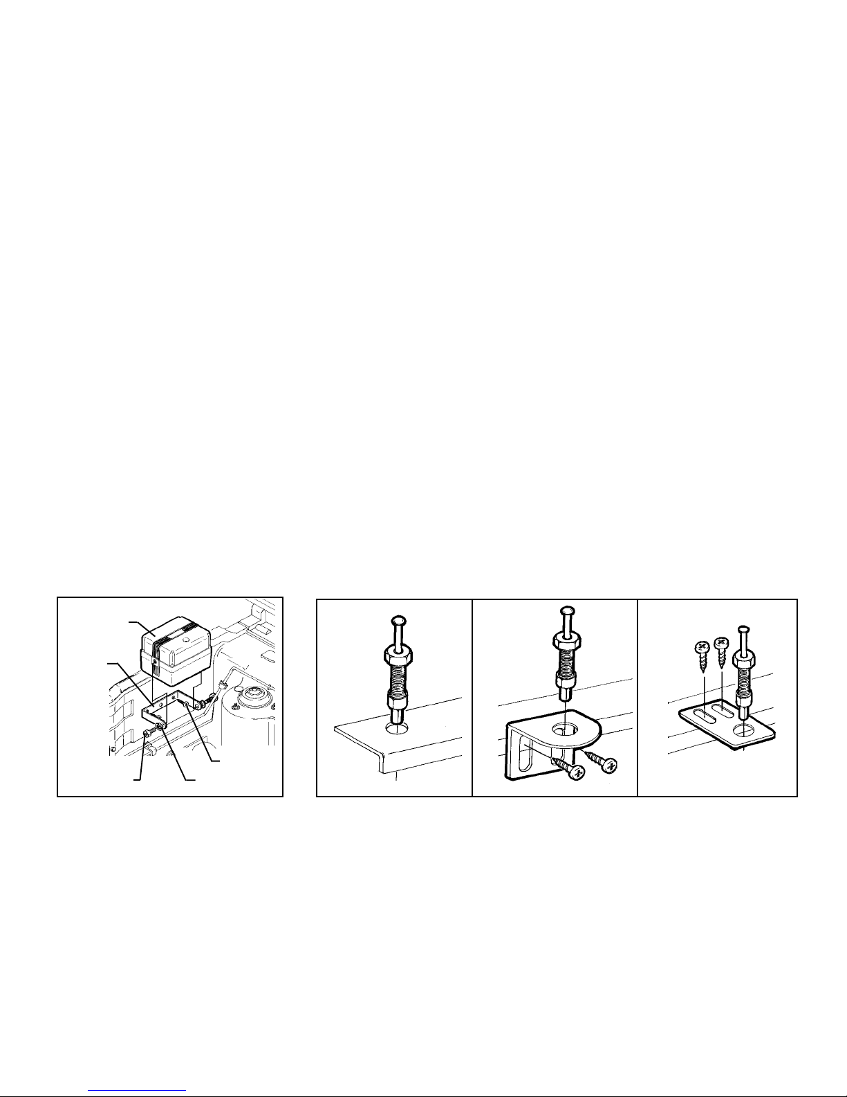
To mount the siren control module;
A. Secure the module mounting bracket to the selected location using
the (2) 3/4" long screws provided.Carefully drill a 1/8" diameter pilot
hole for starting the screws.
B. In most cases, if the bracket has been secured to a solid metal
surface, you can connect theBLACK wire from the wiring harness to
the siren mountingbolt. Using a10 mm wrench or socket, secure the
siren module ( and eyelet terminal on the end of the BLACK wire) to
the bracket using the (2) 3/8" long hex head bolts and (2) split lock
washers provided.
2. Mounting the Hood and Trunk Pin Switches
Two pin switches are provided to protect the hood and trunk lids of the
vehicle, and should be used on any hood or trunk lid that does not turn
a courtesy light on. The switches must always be mounted into a
grounded metal part of the vehicle,as they simplywill not operatewhen
mounted into plastic or fiberglass.
The mounting surface must be at a height that will cause the plunger to
depress 1/4 “ when the hood or trunk lid is closed.
IMPORTANT ! Since the pin switch is designed to be depressed when
the hood / trunk lid is closed onto it, a dimple can occur on the exterior
paint surface if the switch ismounted where itwill contact asingle metal
thicknessarea of the hood /trunk lid.Alwaysmount the pin switch where
it will contact a double wall area of the hood / trunk lid.
When choosing the pin switch mounting location, it is important to
position the switch and/or bracket where water cannot collect or flow.
Avoid all drip “ gutters “ on hood / trunk fenders. Look for locations that
are sealed with rubber gaskets when the hood / trunk lid is closed.
Excessive water on these parts will cause corrosion, resulting in a loss
of protection to the hood / trunk lids. Also,any holesmade to mount the
switches will rust when water is allowed to penetrate. There are three
different mounting methods available. They are;
1. Direct mounting into a trunk lip, radiator cross brace, etc.
A. Drill a 1/4 “ diameter hole into the selected mounting surface. Be
sure there is adequate clearance behind the surface for the pin
switch.
B. Thread the pin switch into the hole using a 7/16 “ wrench or deep
well socket.
2. Mounting using the right angled bracket.
A. Secure the bracket to the desired mounting surface using(2)
sheet metal screws.
B. Screw the pin switch into the bracket.
NOTE : The height of the pin switch can be adjusted by loosening the
screws and sliding the bracket up or down.
3. Mounting using the flat bracket.
A. Secure the bracket to themounting surface using( 2 )sheet metal
screws.
B. Screw the pin switch into the bracket.
NOTE : This bracket can be bent to accommodate specific mounting
requirements.
SIREN MODULE
BRACKET
3/8" LG. HEX BOLTS
3/4" LG. SCREWS
SPLIT LOCKWASHER
1
2
3
Page 1
Page 4
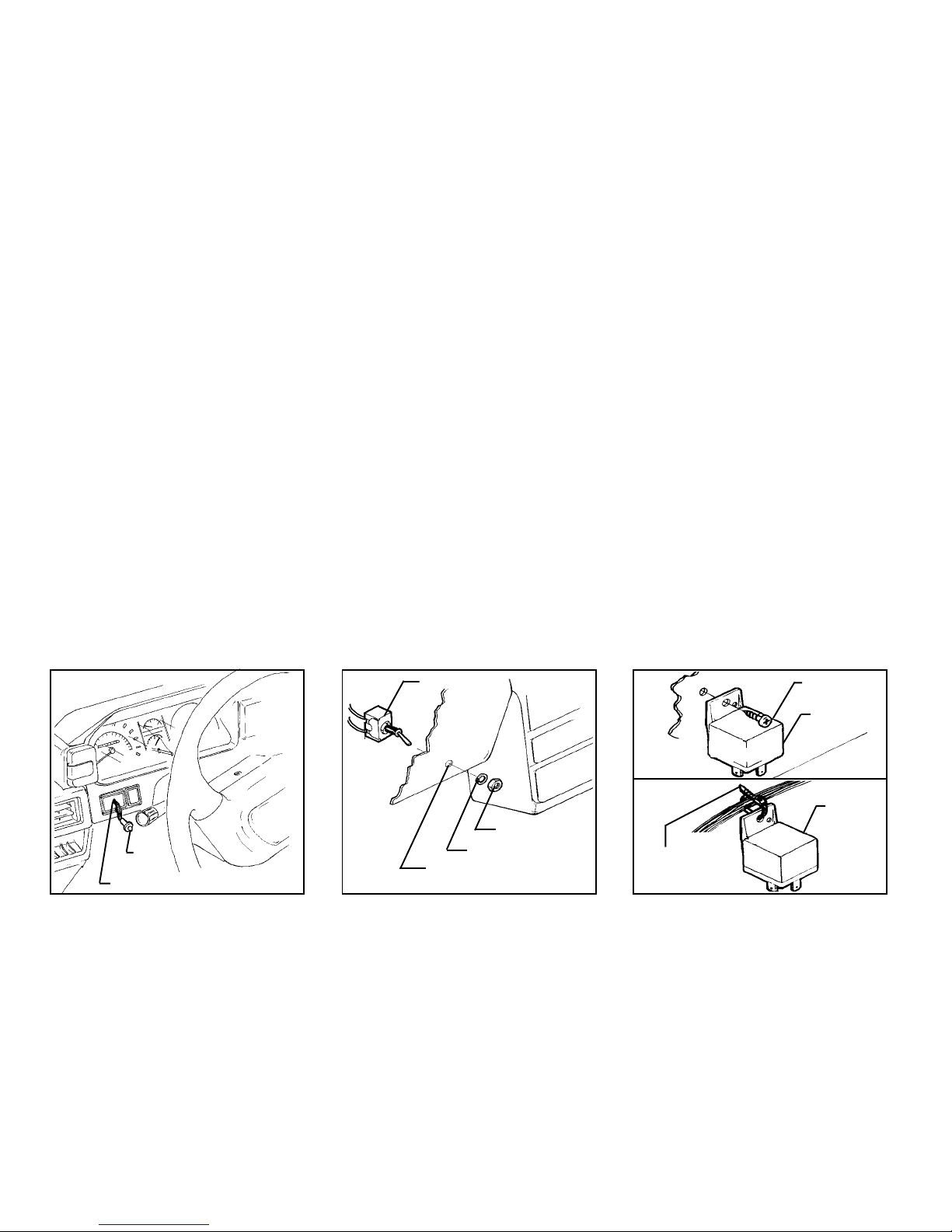
3. Mounting The Dash L.E.D. Indicator
Select an area on the dashboard or center console that will provide the
most visibility from all angles outside the vehicle ( driver’s window,
passenger’s window, rear window, etc. ).
IMPORTANT ! Make sure there is adequate room for the body of the
L.E.D.behindthepanel in the selected location. You should alsobe sure
thatthedrill will not pierce any wires,or damageother components after
passing through the panel. It is always best to remove the panel from
the vehicle before drilling the hole.
To mount the L.E.D.;
A. Drill a 1/4" diameter hole at the selected mounting location.
B. Pass the L.E.D. wires through the hole fromthe front of the panel,
and press the body of the L.E.D. into the hole until fully seated.
4. Mounting the Valet Toggle Switch
Select a flat area on the lower dash lip, where the switch is readily
accessible to the driver, but will not be accidentally bumped. Other
alternate locations are on the driver’s side kick panel, or the side of the
lower steering column cover.
Since this is a “ protected “ ( will only operate when the key is in the
ignition ) bypass switch, it does not have to be concealed, however
concealingtheswitch is always recommended, asthis providesan even
higher level of security to the vehicle.
IMPORTANT ! Make sure there is adequate room behind the panel for
the body of the switch in the selected location. Youshould alsobe sure
thatthe drill will notpierce any wires, ordamage other components after
passingthrough the panel. It isalways bestto removethepanel from the
vehicle before drilling the hole.
To mount the valet bypass switch;
A. Drill a 9/32 “ diameter hole in the selected switch location.
B. Pass theswitch through thehole from behindthe panel, andsecure
from the front using the split lockwasher and hex nut provided.
5. Mounting the Relay
The relay can be mounted in the engine compartment, but it is best to
mount it in the passenger’s compartment, where it will not be exposed
to the environment. If the relay will be used to disable the vehicle’s
starter, mount the relay close to the wires fromthe ignitionswitch. If the
relay will be used to flash the vehicle’s parking lamps, mount the relay
near the front parking light cluster.
To mount the relay;
A.Screwthe relay to the mounting surface,using a sheetmetal screw
through the hole in the relay mounting tab.
B. Secure the relay to an existing wire harness or other component
using cable ties.
L.E.D.
DRILL A 1/4" DIAMETER HOLE
TOGGLE SWITCH
HEX NUT
SPLIT LOCKWASHER
DRILL A 9/32" DIAMETER HOLE
Page 2
MOUNT INSIDE
PASSENGER'S
COMPARTMENT
WIRE TIE TO EXISTING
HARNESS IN VEHICLE
SHEET METAL
SCREWS
RELAY
RELAY
Page 5
WIRING THE SYSTEM
Making the connections to the vehicle, as described in this wiring
section,may be beyond thetechnical abilities of theaverageconsumer.
If you have any questions with the wiring procedures, please call a
qualified automotive technician, or call the AUDIOVOX HOT LINE at 1
-800 - 225 - 6074.Priorto making any connections, a12Volt logic probe
should be used to confirm the proper connection point.
IMPORTANT!The 9 pin white connector onthe end ofthe mainharness
that plugs into the siren control module should remain disconnected
duringthewiringportion of the installation. Leaving this disconnected will
ensure that the keychain transmittersare properly programmed later in
the installation.
1. Routing The Wiring Harness
The DARK BLUE, GRAY, ORANGE, BROWN, and WHITE wires must
be routed through the firewall, and into the passenger compartment of
the vehicle.
In most cases, the RED wire will also be routed into the passenger
compartment,to the courtesy light fuse.Before proceedingwith thewire
routing, verify the location of the courtesy light fuse, as a small
percentage of vehicles locate thisfuse inthe engine compartment, and
inthese cases, it willnotbe necessary to routethe RED wire through the
firewall.
Ifyouhave installed a pin switchinto thetrunk, youwill alsoneed toroute
the DARK GREEN extension wire through the firewall, and to the
previously installed trunk pin switch.
After confirming these component locations, route the DARK BLUE,
WHITE,GREY and RED wires towardstheirconnection points. Caution
should be used when routing wires. Keep wires away from all hot
surfaces,andany moving parts of the vehicle( radiatorfans, accelerator
or brake pedal linkage, etc. ).
When routing wires through the firewall, be sure to pass the wires
through an existing rubber grommet. Failure to do this can result in
damage to wiresfrom sharp metal edges, andan eventual failure of the
security system.
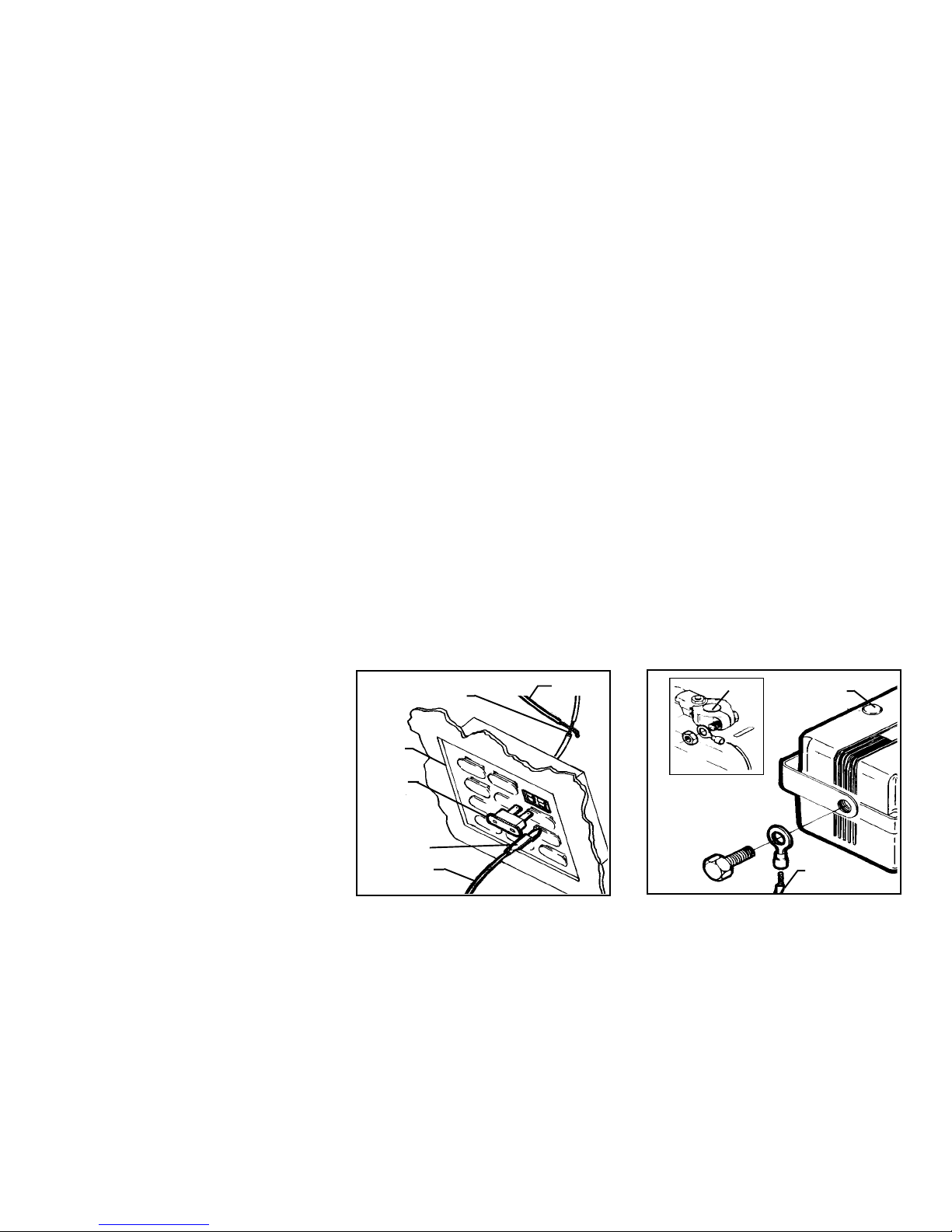
2. Connecting the RED Wire
Locate the courtesy lamp fuse. Both sides of the fuse will indicate + 12
Volts on the logic probe while the fuse is plugged in. Remove the fuse,
and test the contacts that the fuse plugs into. One of the contacts will
not indicate + 12 Volts. This is where the RED wire will be connected.
Connection Method A;
A. Locate the wire coming from this fuse terminal at the back of the
fusebox.
B.Splicethe RED wire from theharness tothis wire,andinsulate with
electrical tape.
Connection Method B;
A. “ Fuse clip “ terminals, which will plug in with the contacts of the
fuse, are available at most electronics stores. This method of
connection may be easier in some vehicles.
B. Refer to the specific instructions included with the fuse clip
terminals.
SPLICE INTO WIRE AND WRAP
WITH ELECTRICAL TAPE
FUSE BOX
COURTESY
LIGHT FUSE
FUSE CLIP TERMINAL
(NOT INCLUDED)
RED WIRE
B
RED WIRE
A
Page 3
3. Connecting the BLACK Wire
The larger BLACK wire ( not the thin black antenna wire ), should have
beenconnectedto ground during the siren module mountingprocedure.
If you were unsureof the groundreliability of thesiren module mounting
bracket,you can connect theeyeleton the end oftheBLACK wire to any
non painted bolton thefirewall or fender, which isthreaded directly into
a metal surface of the vehicle.
NEGATIVE TERMINAL
SIREN MODULE
BLACK WIRE
Page 6
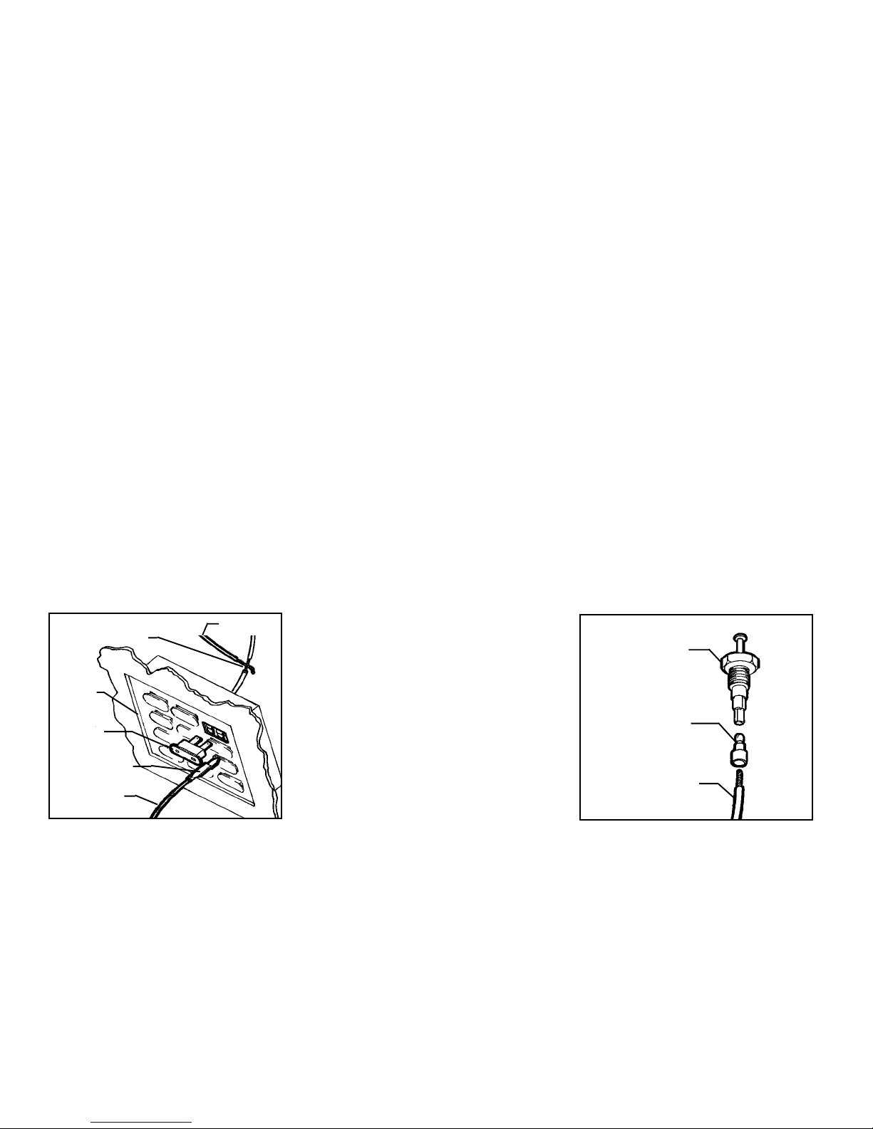
4. Connecting the WHITE wire
Locate a fuse in thevehicle’s fusebox that shows + 12 volts on the logic
probe when theignition key is switched tothe “ ON “ or “ RUN “position,
andshows 0 volts whenthe key is switchedtothe “ OFF“ position( radio
or wiper fuse ).
After you have located a suitable fuse, switch the ignition key to the
“ ON “ position, remove thefuse, and probethe contacts wherethe fuse
plugs into. One of thecontacts will not show 12 volts onthe logic probe;
this is where the WHITE wire will be connected.
Connection Method A;
A. Locate the wire coming from this fuse terminal at the back of the
fusebox.
B. Splice the WHITE wire from the harness to this wire, and insulate
with electrical tape.
Connection Method B;
A. “ Fuse clip “ terminals, which will plug in with the contacts of the
fuse, are available at most electronics stores. This method of
connection may be easier in some vehicles.
B. Refer to the specific instructions included with the fuse clip
terminals.
SPLICE INTO WIRE AND WRAP
WITH ELECTRICAL TAPE
FUSE BOX
RADIO FUSE,
WIPER FUSES, ETC.
FUSE CLIP TERMINAL
(NOT INCLUDED)
WHITE WIRE
WHITE WIRE
A
B
5. Connecting the BROWN wire
Continue to routethe BROWN wire( along with the DARK GREEN wire
for connection to the trunk pin switch ) to the back of the vehicle, and
remove the panels to gain exposure to the reverse lights.
Switch the ignition key to the “ ON “ position ( DO NOT START THE
VEHICLE ), set the parking brake, and move the gear shift selector to
reverse.Movetothe back of the vehicle, andverify that theback up lights
are on.
Probe the wires going to theback up light bulb, and locate the wire that
shows + 12 volts on the logic probe. Move the gear shift selector back
to the park position, and verify that this same wire now shows 0 volts.
This is where the BROWN wire will be connected.
Splice the BROWN wire to this wire, and insulate with electrical tape.
6. Connecting the L.E.D.
6a. Connecting the DARK BLUE wire
ConnecttheDARK BLUE wire from the main harnessto theBLUE
wire from the dash mounted L.E.D. Be sure to insulate this
connection with electrical tape.
6b. Connecting the RED wire from the L.E.D.
Splice the Red wire from the dash mounted L.E.D. to the larger
RED wire from the main harness. Be sure to insulate this splice
with electrical tape.
7. Connecting the Valet Switch
7a. Connecting the GRAY wire
Connect the GRAY wire from the main harness to the GRAY wire
from the Valet Switch. Be sure to insulate this connection with
electrical tape.
7b. Connecting the BLACK wire from the Valet Switch
Connect the BLACK wire from the Valet Switch to a solid,
grounded, metal part of the vehicle. It can be connected to any
metal,non- painted bolt that screws into theinner framein the kick
panel.
Page 4
8. Connecting the DARK GREEN wire
Trim the DARK GREEN wire to the proper length, strip 1/4 “ of the
insulation, and crimp one of the male bullet terminalsprovided ontothe
endofthe wire. Plug thebullet terminalonto thereceptacle atthe bottom
of the hood pin switch.
If you have installed a trunk switch, you should have already routed the
DARKGREEN extension wire tothe rearofthe vehicle. Crimp the bullet
terminal onto the end of the extension,and plug itonto the bottomof the
trunk pin switch. You will also need to splice theother endof the DARK
GREEN extension wire to the DARK GREEN wire from the main
harness, and insulate the splice with electrical tape.
PIN SWITCH
MALE BULLET
TERMINAL
GREEN WIRE
Page 7
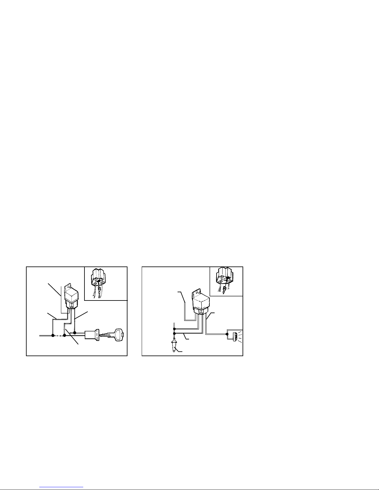
9. Connecting the relay - STARTER CUT FEATURE
IMPORTANT! The relayhas been shippedwith(1)BLACK wire loose.
Whenusing the relay todisablethe starter, load theBLACKwire into the
relay connector in the location shown in the diagram.
9a. Connect theORANGE wire fromthe relay harnessto the ORANGE
wire from the main harness. Be sure to insulate this splice with
electrical tape.
9b. Gain access to the wires coming from the ignition switch. Connect
the RED wire from the relay harness to the wire from the ignition
switch that shows + 12 volts on the logic probe when the key is
switched to the “ ON or RUN “ and “ START “ positions, and shows
0 volts when the key is switched to the “ OFF “ position. Be sure to
insulate this connection with electrical tape.
9c. Locatethe wire coming from theignition switchthatshows + 12 volts
on the logic probe when the starter motor is cranking, andshows 0
volts when the keyis switched tothe “ OFF“, “ ACCESSORY“, and
“ ON or RUN “ positions. Cut this wire and try to start the vehicle to
verify that the starter motor will not engage.
Connectthe WHITE w/BLACKstripe wire fromthe relay harness toone
sideof the cut starterwire, andconnectthe BLACK wire tothe otherside
of the cut wire.
CAUTION ! Be sure these wires are securely connected, and properly
insulated. If this connection separates, the vehicle will not start, even
when using the ignition key.
ORANGE WIRE-SPLICE TO
ORANGE WIRE FROM
SIREN MODULE HARNESS
CONNECT BLACK
TO ONE SIDE OF
THE START WIRE
CONNECT WHITE w/BLACK STRIPE WIRE
TO OTHER SIDE OF START WIRE
RED WIRE-SPLICE TO
THE IGNITION WIRE
10. Connecting the relay - PARKING LIGHT FLASH
FEATURE
IMPORTANT! The relayhas been shipped with(1)BLACKwire loose.
When using the relay to flash the vehicle’s parking lights, load the
BLACK wire into the relay connector in the location shown in the
diagram.
10a.Connect the ORANGE wirefrom therelay harnessto the YELLOW
wire from the main harness. Be sure to insulate this splice with
electrical tape.
10b. Gain access to the wires coming from the back of one of the front
parking lamp sockets. Switch the parking lights on, and locate the
wire that shows + 12 volts on the logic probe. Switch the parking
lights off, and verify that this wire now shows 0 volts. Connect the
BLACK wire from the relay socket to this wire, and insulate the
connection with electrical tape.
10c. Connect both the RED wire from the relay socket and the WHITE
w/ BLACK stripe wire from the relay socket toa+12volt battery
fusedwire ( minimum15 Amp fuse)in the vehicle.These wires can
be connected to the positive battery terminal, however when
connecting them to the positive battery terminal, you must add an
in line fuse of at least 15 Amps. Connect one sideof thefuse tothe
positive battery terminal, and the other side of the fuse to the RED
and WHITE w/ BLACK stripe wires from the relay connector.
ORANGE-SPLICE TO
YELLOW WIRE FROM
SIREN HARNESS
BLACK-SPLICE
TO PARKING
RED
WHITE/BLACK
+12 VOLT CONSTANT FUSED WIRE
LIGHT WIRE
Page 5
11. 2 Pin Door Lock Interface Connector
There is an additional 2 pin connector coming out of the siren control
module, with a RED and a BLACK wire. This connector is used for the
optional door lock interface, which will remotely lock and unlock your
vehicle’sexistingpowerdoor locks when arming and disarming. Only the
AA 9158 door lock interface should be used with this alarm. If you are
not installing the door lock interface, do not make any connections to
these two wires.
PROGRAMMING THE KEYCHAIN TRANSMITTERS
The two keychain transmitters that are included with this system are a
“code learning “ type RadioFrequency transmitter,whichsimply means
thatthesirencontrol module will learn and rememberthe individual code
number of each transmitter. The siren control module will learn the
individual codes of (2) transmitters only. An attempt to program a third
transmitter will erase the code number of the first transmitter programmed.
IMPORTANT ! Save these programming instructions in a place where
you can easily find themin the future. Whenever the vehicle’s batteryis
disconnected for servicing, the transmitters will need to be reprogrammed.
To Program the Transmitters;
A. The main harness connector should be disconnected from the
siren control module at this step of the installation procedure. If it
is not, unplug the connector.
B. Be sure to have both keychain transmitters in hand, then plugthe
mainharnessconnector into the siren control module. Youshould
hear a short “chirp” from the siren.
C. Press and hold the larger arming button on transmitter number 1
until the siren sounds one long “ chirp “.
D. Immediatelypress andhold the larger armingbutton on transmitter
number 2 until the siren sounds one long “ chirp “.
E. Both transmitters should now be programmed. You can test this
by pressing the arming button on each transmitter, which will
result in the appropriate “ ARMED “ or “ DISARMED “ indication
from the siren module.
IMPORTANT ! If only one transmitter isoperating, repeat the programming procedure. Once the harness connector is plugged in, you have
only 15 seconds in which to program both transmitters. This short time
window is required in order to provide a high level of security.
Page 8

COMPLETING THE INSTALLATION
Youwill notice (5) additionalwires,which come directly outof the rubber
wire exit boot fromthe siren controlmodule, and arenot part of the main
harness. These wires are used to customize the installation, and are
required in some vehicles.
1. Thin BLACK Wire
This is theantenna wire forthe receiver that is built into the sirencontrol
module. Fully extend this wire, and route it as high in the engine
compartment as possible, for maximum transmitter range.
2. BLACK Loop Wire
This pair of wires exits the rubber boot, and are terminated with 1/8 “
mating male and female spade connectors.
Thissystem can be programmed toarmactively or passively. Insurance
discounts are usually larger for passive arming security systems.
Active arming means that the security system will only arm when the
transmitterbuttonis pressed. To select the active armingfeature, simply
plug the two terminals on the BLACK wire loop together.
Passive arming means that the security system will automatically arm
60 seconds after the ignition key has been switched off. You still have
theoption of armingthesystem immediately bypressing the transmitter
button, but ifyou forget to do this,the system will automatically arm and
provide full protection to the vehicle. To select the passive arming
feature, be sure the two terminals on the BLACK wire loop are
disconnected, and individually insulate each end with electrical tape.
3. BLUE Loop Wire
This wire exits the rubber boot, and immediately loops back into the
rubber boot.
The siren control module is programmed at the factory for voice
activation. If you wish to eliminate the voice response of the system
( replace theword “ ARMED “ with one single “chirp “- replace theword
“ DISARMED “with two “chirps “ -replace the word“ INTRUSION “ with
four “ chirps “ - and replace the words “ ATTENTION, BACKING UP “
with “ threechirps..pause..three chirps..etc. “ ), simply cut thisblue wire
loop, and individually insulate both sides with electrical tape.
NOTE : The “ ATTENTION INTRUSION “voice message during the 60
second alarm cycle will always be active. There is no way to eliminate
this voice message.
4. WHITE Loop Wire
This wire exits the rubber boot, and immediately loops back into the
rubber boot.
Three minutes after the alarm has been armed, the voltage sensing
circuitrybecomesactive.This voltage sensing monitors the voltagelevel
of the vehicle, and when it sees a change ( i.e. a door opens, and the
interior light turns on ), the alarm is triggered.
Manyvehiclesincorporatean electronic cooling fan, which willautomatically switch on after the vehicle has been turned off.If thisfan switches
onshortlyafter the alarm has been armed, thesystem willnot trigger due
to the three minute delay.
If your vehicle does not have an electronic cooling fan which turns on
after the vehiclehas been turned off, youmay elect to by passthe three
minute arming delay of the voltage sense circuit. The system can be
modified so that six seconds after arming, the voltage sensing circuitry
becomes active. The three minute time delay can be eliminated by
cutting the WHITE wire loop. After cutting the WHITE wire loop,
individually insulate both ends of the wire with electrical tape.
Do not cut this loop ifyour vehicle isequipped with anelectronic cooling
fan, as you will experience false alarms.
5. GREEN Loop Wire
This wire exits the rubber boot, and immediately loops back into the
rubber boot.
Cutting this wire will eliminate the voltage sensing feature of the alarm.
When this wire is cut, opening the doors will not trigger the system.
This loop wire should be cut only if you want to protect the vehicle from
sudden impacts to the glass or body panels, but do not want the alarm
to trigger when a door has been opened.
6. Final Touches
If there are any wires from the main harness that you did not connect,
simply because you did not wish to activate a particular feature, you
shouldeither insulate theends of thesewires with electrical tapeand tie
them where they cannot be damaged, or simply remove any unused
wires from the main harness connector.
ADJUSTING THE SENSITIVITY OF THE SHOCK SENSOR
The purpose of a shock detector is to “sense” strong impacts to the
vehicle’s glass and body panels, but ignore light bumps to the vehicle.
This alarm is programmed to report these impacts in two ways.
A lighter impact will cause the alarm to sound a series of short “chirps”,
warning anyone tampering with the vehicle to stop immediately.
Amoreforceful impact will cause the alarm tosound forit’s full 60second
cycle, informing you that a serious violation attempt has occurred.
IMPORTANT ! Setting the sensitivity of the shock sensortoo high will
cause false alarms. A substantial amount of force is required to
actually break automotive glass, and the shock sensor should be set
accordingly.
Before proceeding with the adjustment, make sure that all screws
securing the siren control module to the bracket, and securing the
bracket to the vehicle, are securely tightened.
To adjust the shock sensor;
A. Locate and remove the small rubber plug on the back of the siren
control module.
B. Gently turn the adjustment screw fully counter - clockwise, then
clockwise approximately 1/8of a turn.Do not over turn thisscrew, as
maximum rotation is approximately 270º. You should stop applying
pressure as soon as you feel a slight amount of resistance.
C. Close the hood, arm the alarm ( ARMED or “ 1 CHIRP “ ), and allow
six seconds for the shock sensor to stabilize.
D. Firmly strike the front bumper of the vehicle with the side of a closed
fist, considering the amount of force required to break a window.
CAUTION !Never perform this test on the vehicle’s glass, as you may
break a window.
E.If the alarm didnot sound,orif only the warningchirpswere activated,
then the sensitivity will need to be increased. Disarm the alarm, and
open the hood to gain access to the siren control module.
F. Gently turn theadjustment screw approximately 1/8 turn clockwise (
increasing sensitivity ), and repeat the test.
G. Repeat this procedure until a firm strike causes the alarm to trigger,
and a less forceful impact causes the alarm to sound the warning
chirps.
H. When the adjustment is set, replace the rubber plug on the back of
the siren module.
Page 6
Page 9

OPERATING THE SYSTEM
In this section, theoperation of thesystem is describedaccording to the
voicemessagesthat are programmed into the siren controlmodule. The
equivalent chirp tones are shown in parenthesis for those users that
have disabled the voice ( see blue wire loop ).
Additionally, if the relay included in the package was used to flash the
parking lights, the parking light indications will be shown in brackets
[].
1. Arming the System
A. Exit the vehicle, and close and lock all doors.
B.Press and releasethe larger arming buttonon the keychaintransmit-
ter. The system will respond with “ARMED” ( one single chirp). [ one
flash ].
C. The red dash mounted L.E.D. will begin to flash, and after approxi-
mately six seconds, the shock sensing feature of the system will be
activated. The voltage sensing circuit will begin its countdown, and
after approximately threeminutes, opening a light activateddoor will
trigger the alarm.
D. If the system has been installed usingthe automatic passive arming
feature,then 60 seconds after switchingthe ignitionkeyoff, the alarm
will automatically arm providing the hood and trunk lids are closed.
During the 60 second automatic arming cycle, the dash mounted
L.E.D. will flash rapidly.
IMPORTANT ! If the WHITE loop wire was cut during the installation
procedure, the voltage sensing feature of the alarm will become active
sixseconds after arming thesystem (seeCOMPLETING THE INSTALLATION, WHITE Loop Wire ). You will not need to wait the three
minutes, before opening a door will cause the alarm to trigger.
2. Protection While the System is Armed
A. Opening a door ( or any light activated entry point ), will cause the
alarm to immediatelysound for the complete 60 second alarmcycle.
If the relay was installed to flash the parking lamps, then the parking
lights will flash on and off during the 60 second alarm cycle.
B. If the relay was installed to disable the vehicle’s starter, then any
unauthorized attempt to start the vehicle will be prevented.
C. While the system is armed, the red dash mounted L.E.D. will
constantly flash, discouraging any would be thieves.
D. Any light impact to the vehicle glass or body panels will cause the
system to immediately sound the warning chirps, discouraging any
further attempts to enter the vehicle.
E. Any forceful impact to the vehicle will cause the system to immedi-
atelytrigger for thecomplete60 second alarmcycle. At the endof the
cycle,the alarm will re -arm itself,and resumemonitoringthe vehicle.
3. Disarming the System
A. When you return tothe vehicle, press and releasethe larger arming
button on the keychain transmitter. The system will respond with
“ DISARMED “ ( two chirps ). [ two flashes ].
B1. If the alarmhasbeen wired for ACTIVEoperation, then the reddash
mounted L.E.D. will turn off, indicating that the system is disarmed,
and it is safe to enter the vehicle.
B2. If the alarm has been wired for PASSIVE operation, then the red
dash mounted L.E.D. will begin to flash rapidly, indicating that the
system is disarmed, but in the automatic re - arming mode. Within
60secondsof disarming the system,you willneed toturn theignition
key to the on position to stop the system from re - arming.
4. Disarming After an Intrusion
When disarming, if the system responds with “ INTRUSION “ ( four
chirps ) [ three flashes ], you are being alerted that the alarm was
triggered during your absence. Additionally, the red dash mounted
L.E.D. will blink 3 times .. pause .. blink 3 times .. etc., to provide an
added visual indication that the alarm had been triggered. These
intrusion indicators are stored in the system’s memory, and will only be
erased when the ignition key is switched on.
5. Decreasing the Sensitivity of the Shock Sensor via the
Keychain Transmitter
There may be some circumstances when you will want to arm the
system, but decrease the sensitivity of the shock sensor, or simply turn
the shock sensor off. This feature can be useful during extreme
thunderstorms, or when parking on or near heavy construction sites.
To arm and decrease shock sensitivity,
A. Follow thenormal arming procedureby pressing the largerbutton on
the keychain transmitter.
B.Immediatelyafter arming, press and release the smallerbutton onthe
keychain transmitter.
C. In approximately five seconds, the siren will sound one long chirp,
Page 7
indicating that the sensitivity of the shock sensor has been reduced
30 percent.
To arm and turn the shock sensor off,
A. Follow the normalarming procedure bypressing the largerbutton on
the keychain transmitter.
B. Immediately afterarming, pressand release thesmaller button onthe
keychain transmitter two times.
C. In approximately five seconds, the siren will sound one short chirp,
followedby one longchirp, indicating thattheshock sensor hasbeen
turned off.
IMPORTANT ! Any time the shock sensor has beenadjusted using the
keychaintransmitter,disarming then re arming the system willreturn the
shock sensor to its normal operating sensitivity.
6. Remote Panic Operation
Thealarmcanbe activated via the keychain transmitterto draw attention
to your vehicle during an emergency situation.
To activate the panic feature;
A. Press and hold the larger button on the keychain transmitter for 3
seconds.
B. The alarm will sound, and continue to sound for 60 seconds.
C. To silence the alarm before the 60 second shutdown, press and
release the larger button on the keychain transmitter.
WARNING ! In most areas, it is illegal to activate the alarm while the
vehicleismoving.For the safety of your passengersand other motorists,
do not activate the alarm while your vehicle is in motion.
7. Valet Switch Operation
If you lose or misplace your keychain transmitter, or if the transmitter
fails to disarm the system, an emergency bypass switch is included to
temporarily disarm the system.
To use the switch;
A. Open the driver’s door. The alarm will sound !
B. Insert the key into the ignition switch, and turn it to the “on” position.
C.Move the valet switchto the “ON” position.Thealarm will disarm,and
the vehicle can now be started.
D. The dash mounted L.E.D. will turn on solid, and remain on until the
system is switched out of valet mode.
Page 10

TROUBLESHOOTING :
When in the valet mode, all of the security functions of the system are
inoperative, and the system cannot be armed until it is switched out of
valet. The panic feature, and the optional keyless entry feature, will
operate when the system is in the valet mode.
To switch out of the valet mode;
A. Turn the ignition key to the “on” position, then move the valet switch
to the “OFF” position.
B. The dash mounted L.E.D. will turn off, and the system will return to
normaloperation.
8. Backing Up Alert
Foradditionalsafety,especially in residential areas, the systemincludes
a back up alert.
Any time the vehicle is running, and the gear shift selector is moved to
reverse, the system responds with “ ATTENTION BACKING UP“(3
chirps...pause...3 chirps), and repeats this message until the vehicle is
shifted out of reverse.
9. Replacing the Transmitter Battery
The keychain transmitters have a small, red L.E.D. visible through the
topcover. This L.E.D.can be usedtoindicate battery condition.You will
also notice a decrease in effective transmitter range as the battery
deteriorates.
The replacement battery must be a 12 volt type GP23A or equivalent.
To replace the transmitter battery;
A. Remove the small phillips head screw from the bottom of the
transmitter, and carefully pry the top cover ( button side ) away from
the transmitter.
B.Remove the dischargedbattery, making note ofthe orientation ofthe
+ and - contacts, and dispose of properly.
C.Install the newbattery, taking careto place the+ and -contacts in the
correct position.
D. Replace the transmitter cover, taking care not to damage the L.E.D.
or switches on the circuit board.
E. Replace the small phillips head screw through the bottom of the
transmitter.
Symptom : The siren does not chirp when the harness is first plugged
in.
Check :
A.Verifythat the fuse in thered wirefrom thesiren control
module is in good condition. Replace it if it is blown.
B. Verify that the connections of the red and black wires
havebeen made according tothe wiring section ofthis
manual.
Symptom : The transmitters will not program to the siren control
module.
Check :
A. You haveonly 15seconds after applying power tothe
sirencontrolmodulein which to program both transmitters.
Symptom : The alarm will not arm and disarm using the keychain
transmitter.
Check :
A. Verify the transmitter battery is in good condition. Try
both transmitters. Replace the transmitter battery if
necessary.
B. Verify that the transmitter is programmed to the siren
control module. When the vehicle’s battery is disconnected, or when power is removed from the siren
control module, the transmitters need to be re programmed. Follow the programming instructions in
this manual.
C.Verifythat the fuse in thered wire fromthe sirencontrol
module is in good condition. Replace it if it is blown.
D. Verify that the connections of the red and black wires
havebeen made according tothe wiring section ofthis
manual.
Symptom : The alarmwill not soundwhen opening the hoodor trunk lid
where a pin switch was added.
Check :
A. Verify the pin switch is set to the proper height. The
plungeroftheswitch must depress 1/4 “ when thehood
or trunk lid is closed.
B. You must waitapproximately 10 secondsafter arming
before the pin switch circuit is activated.
C. Verify that the pin switch and/or pin switch bracket is
mounted to a grounded metal surface of the vehicle.
Symptom : The alarm will not sound when opening a door that turns a
courtesy light on.
Check :
A. Verify that the light selector switch is in the door
position.
B. Verify that the domelight bulbturns on. The alarm will
only sound if the bulb turns on. Replace the bulb if it is
not turning on.
C. There is a 3 minute delay after arming, before the
courtesylight sensing circuitof thealarm is energized.
Make sure that the full 3 minutes has elapsed.
Symptom : The bypass switch will not disarm the alarm.
Check :
A. The ignition key must be turned to the on position
before activating the switch.
B.Verify the connections to theGRAY wire, BLACKwire
from the switch, and WHITE wire from the main
harness. Repair the connections if necessary.
Page 8
Page 11

SIREN MODULE
THIN BLACK ANTENNA WIRE
2 PIN OPTIONAL DOOR LOCK CONNECTOR
GROUND
GREEN, WHITE AND
BLUE WIRE LOOPS
BLACK
GREY
WIRE LOOP
SPLICE
L.E.D.
GREY
VALET
SWITCH
BLACK
TO GROUND
Printed in Taiwan Audiovox Corp., 150 Marcus Blvd. Hauppauge, N.Y. 11788 Form No. 128-4430
BLUE
BLUE
RED
TO +12V CONSTANT
IN VEHICLE'S
BLACK
FUSEBOX
RED
YELLOW
ORANGE
CONNECT THE ORANGE WIRE FROM
THE RELAY TO EITHER THE ORANGE
WIRE FROM THE MAIN HARNESS
THE YELLOW WIRE FROM THE MAIN
HARNESS
HOOD & TRUNK
PIN SWITCHES
GREEN
OR
BROWN
WHITE
TO VEHICLE'S
REVERSE LIGHTS
TO +12V ACCESSORY
IN VEHICLE'S FUSEBOX
START CUT
OR
PARK LIGHT
RELAY
ORANGE
Page 9
Page 12

MONTAGE DES COMPOSANTS
1. Montage du module de commande de la sirène
Choisir une surface métallique plane à l’intérieur du compartiment du
moteur, mais qui ne soit pas sur le moteur, pour monter le module de
commande de la sirène. Il faut garder à l’esprit que le côté de
l’avertisseur doit être tourné vers le bas pour empêcher que l’eau ne
pénètre dans le module.
Unemplacement sur la cloison pare-feu à laquelle onnepeut accéder
depuis le dessous du véhicule est préférable. Un tel emplacement
fournit des conditions de fonctionnement optimales au capteur de
vibrationsetempêche tout malfaiteur éventuel dedéconnecter l’alarme
par le dessous du véhicule.
Il faut aussi que le module de commande soit placé aussi loin que
possible des composants chauds ou mobiles à l’intérieur du
compartimentdu moteur, et ilfaut également éviter leszones où l’eau
risque de couler ou de s’accumuler pendant les gros orages.
Pour monter le module de commande de la sirène:
A.Fixer la patte de support de montage du module à l’emplacement
choisià l’aide des deux (2)visde 1,9 cm (3/4")de long fournies avec
le module. Ilfaut percer avecprécautions un trou pilote de0,32 cm
(1/8") de diamètre pour amorcer les vis.
B.Dans la plupart des cas, lorsque la patte de support a été fixée sur
unesurface métallique solide, on peut connecterlefil NOIR sortant
du faisceau de conducteurs au boulon de montage de la sirène.
Avec une clé ou une douille de 10 mm, fixer le module de la sirène
(et la borne en illet située à l’extrémité du fil NOIR) au support à
l’aide des deux (2) boulonsà tête hexagonale de 0,95 cm (3/8")de
long et des deux (2) rondelles de blocage fendues fournis avec le
module.
MODULE
DE LA SIRÈNE
SUPPORT
2. Montage des commutateurs à fiche des capots du
moteur et du coffre
Deux commutateurs à fiche sont fournis pour protéger les capots du
moteur et du coffre du véhicule, et il faut les utiliser avec tout capot
qui n’allume pas automatiquement une lampe de service. Les
commutateursdoiventtoujours être montés dans unepartie métallique
du véhicule mise à la masse, car ils ne fonctionnent absolument pas
lorsqu’ils sont montés sur une partie en matière plastique ou en fibre
de verre.La surface de montage doit être à une hauteur permettant à
la fiche de s’enfoncer de 0,64 cm (1/4") lorsque les capots du moteur
ou du coffre sont fermés.
ATTENTION! Comme le commutateur à fiche est conçu pour être
enfoncé lorsque le capot se referme sur lui, ceci risque de créer une
bosse dans le métal et d’écailler la peinture à l’extérieur si le
commutateurentre en contact avec unepartie métallique du capotde
simple épaisseur à cet endroit-là. C’est pourquoi il faut toujours
monter le commutateur à fiche à un endroit où il pourra entrer en
contact avec une partie métallique du capot de moteur ou de coffre
ayant une double épaisseur.
Lorsqu’on choisit l’emplacement du commutateur à fiche, il est
important de veiller à ce que ni le commutateur ni la patte de support
ne soient à un endroit où l’eau puisse s’accumuler ou couler. Il faut
éviter toutes les gouttières du capot sur les ailes/le coffre. Il faut
rechercher les emplacements étanchéspar des jointsen caoutchouc
lorsque les capots du moteur/du coffre sont fermés. Trop d’eau sur
ces pièces risquerait de les corroder, ce qui aboutirait à diminuer la
protection des capots. Tous les trous perforés pour monter les
commutateurs risqueraient également de rouiller si l’eau pouvait y
pénétrer. Il existe trois méthodes de montage différentes, à savoir:
1
2
1.Montage direct dans une lèvre du coffre, un croisillon de
radiateur, etc.
A.Percer un trou de 0,64 cm (1/4") dans la surface de montage
choisie. Il faut s’assurer qu’il existe un dégagement suffisant
derrière la surface pour le commutateur à fiche.
B.Visser le commutateuràfiche dans le trou à l’aide d’une clé à douille
ou d’une douille de 1,11 cm (7/16").
2.Montage à l’aide d’une équerre de support.
A.Fixer l’équerre àlasurface de montage choisie à l’aidedesdeux (2)
vis à métaux.
B.Visser le commutateur à fiche dans l’équerre.
REMARQUE: On peut régler la hauteur du commutateur à fiche en
desserrant les vis et en faisant glisser l’équerre vers le bas ou vers le
haut.
3.Montage à l’aide d’une patte de fixation plate.
A.Fixer la patte à la surface de montagechoisie à l’aide des deux (2)
vis à métaux.
B.Visser le commutateur à fiche dans l’équerre.
REMARQUE: On peut courber cette patte de fixation pour l’adapter
aux conditions de montage particulières.
3
VIS DE 1,9 CM
BOULONS À TÊTE
HEXAGONALE DE
0, 95 (3/8") DE LONG
(3/4") DE LONG
RONDEL LE DE
BLOCAGE FENDUE
Page 10
Page 13

3.Montage de l’indicateur D.E.L. du tableau de bord
Choisir l’emplacement sur le tableau de bord ou au centre de la
console qui sera le plus visible de l’extérieur du véhicule, à partir de
tousles angles possibles (fenêtre duconducteur,fenêtres passagers,
lunette arrière, etc.).
ATTENTION! Il faut s’assurer qu’ilexiste suffisammentdeplace pour
lecorps de la D.E.L. derrière le panneau demontageà l’emplacement
choisi. Il faut également veiller à ce que la perçeuse ne sectionne
aucun fil et n’endommage aucun composant après avoir percé le
panneau.Ilest toujours recommandé d’enlever lepanneau du véhicule
avant de percer le trou.
Pour monter la D.E.L., il faut:
A.Percerun trou de 0,64 cm (1/4") de diamètre à l’emplacement choisi
pour l’installation.
B.Faire passer les fils de la D.E.L. à travers le trou à partir de l’avant
du panneau, et enfoncer le corps dela D.E.L. dans letrou jusqu’à
ce que celle-ci soit bien assise.
D.E.L.
PERCER UN TROU DE 0,64 CM
(1/4") DE DIAMÈTRE
4.Montage de l’interrupteur à bascule de secours
Choisir une zone plane sur le rebord inférieur du tableau de bord, à
un endroit où l’interrupteur soit facile d’accès pour le conducteur,
sans qu’il risquepourtant d’être accidentellement accroché. On peut
proposercomme autres emplacements possibles, le panneaulatéral
inférieur près des pédales, ou le côté inférie ur de la colonne de
direction.
Comme il s’agit d’un interrupteur “protégé” (qui ne fonctionne que si
la clé de contact est dans le démarreur), monté en couplage, il n’est
pasindispensable de le cacher; pourtant,il \est toujours recommandé
de cacher cetinterrupteur car ceciconfère un niveau de sécurité plus
élevé au véhicule.
ATTENTION! Il faut s’assurer qu’il se trouve suffisamment de place
derrière le panneau pour le corps de l’interrupteur, à l’emplacement
choisi. Il faut également veillerà ce que la perçeuse ne sectionne
aucun fil et n’endommage aucun composantaprès avoir percé le
panneau.Ilest toujours recommandé d’enlever lepanneau du véhicule
avant de percer le trou.
Pour monter l’interrupteur de secours en couplage, il faut:
A.Percerun trou de 0,71 cm (9/32") de diamètreà l’endroit choisi pour
installer l’interrupteur.
B.Fairepasser l’interrupteur à traversle troupar l’arrière du panneau,
et le fixer à l’avant à l’aide de la rondelle de blocage fendue et de
l’écrou hexagonal fournis avec l’interrupteur.
INTERRUPTEUR À BASCULE
ECROU HEXAGONAL
RONDELLE DE
BLOCAGEFENDUE
PERCER UN TROU DE 0,71 CM
(9/32") DEIAMÈTRE
Page 11
5. Montage du relais
Lerelais peut être montédans le compartement du moteur, maisil est
plutôtrecommandéde le monter dansle compartimentdes passagers,
où il est protégé des rigeurs de l’extérieur. Si le relais doit être utilisé
pourcouper le démarreur du véhicule, il faut le monter àproximitédes
fils de contact du démarreur. Si le relais doit être utilisé pour faire
clignoter les feux de position du véhicule,il fautle monter à proximité
du faisceau de conducteurs des feux de position avant.
Pour monter le relais, il faut:
A.Visserle relais à la surface de montage, àl’aide d’une visà métaux
que l’on engage dans le trou situé dans la languette de fixation du
relais.
B.Fixer le relais à un faisceau de conducteurs existant ou à un autre
composant à l’aide d’un ou plusieurs attache-câble.
VIS À MÉTAUX
RELAIS
MONTER À
L’INTÉRIEUR DU
COMPARTIMENT
DES
PASSAGERS
RELAIS
ATTACHE-CÂBLE FIXÉE
À UN FAISCEAU DE
CONDUCTEURS
EXISTANT DU VÉHICULE
Page 14

CÂBLAGE DU SYSTÈME
Ilest possible que la réalisation des connexions au véhicule, telles que
décrites dans la présente section relative au câblage, dépasse le
niveaudes connaissances techniques d’unconsommateur moyen.Si
vous avez la moindre question à poser au sujet des méthodes de
câblage, veuillez appeler un électricien spécialiste des circuits
électriques sur véhicules, ou bien encore, appelez AUDIOVOXURGENCES au 1-800-225-6074. Avant d’effectuer une connexion
quelconque, il faut utiliser une sonde logique de 12 volts pour
confirmer que la tension soit correcte au point de connexion.
ATTENTION! Le connecteur blanc à 9 brochessitué à l’extrémité du
faisceau de conducteurs principal, qui se branchedans lemodule de
commandede la sirène, doit rester déconnecté pendant l’opération de
câblage de l’installation. En laissant ce connecteur déconnecté, on
assure que les transmetteurs du porte-clés seront convenablement
programmés, plus tard au cours de l’installation.
1. Acheminement du faisceau de conducteurs
Les fils BLEU FONCÉ, GRIS, ORANGE, BRUN ET BLANC doivent
être acheminés à travers la cloison pare-feu dans le compartiment
des passagers.
Dans la plupart des cas, le fil ROUGE doit aussi être amené dans le
compartimentdes passagers, jusqu’au fusible deslampes de service
(portes, plafonnier). Avant de continuer l’acheminement des fils,
vérifier où se trouve l’emplacement dufusible des lampesde service,
car un faible pourcentage de véhicules ont ce fusible placé dans le
compartiment du moteur, et dans ces cas-là, il n’est pas nécessaire
d’acheminer le fil ROUGE à travers la cloison pare-feu.
Si vous avez installé un interrupteur à fiche dans le coffre, il faut
également que vous acheminiez le fil de rallonge VERT FONCÉ à
traversla cloison pare-feu, jusqu’à l’interrupteurà fiche préalablement
installé dans le coffre.
Après avoir confirméles emplacements descomposants, acheminer
les fils BLEU FONCÉ, BLANC, GRISET ROUGE versleurs points de
connexion.Il faut agir avecprécaution lorsqu’onachemineles câbles.
Il faut éviter que les fils touchent des surfaces chaudes et mobiles à
l’intérieur du véhicule (ventilateurs de radiateur, tringlerie de
l’accélérateur ou de la pédale de frein, etc.).
Pour traverser la cloison pare-feu, il faut veiller à ce que les fils
passent à travers un canon isolant en caoutchouc déjà en place. A
défaut de procéder ainsi, les conducteurs risqueraient de
s’endommager en frottantcontre les bords coupants du métal, cequi
pourraitéventuellemententraîner la défaillance du système de sécurité.
2. Connexion du fil ROUGE
Repérer le fusible des lampes de service. Les deux côtés du fusible
doivent indiquer +12 volts sur lasonde logique pendantque le fusible
est enfiché. Enlever le fusible et tester les contacts dans lesquels le
fusibles’enfiche. L’un des contactsn’indiquera pas +12 volts. Ceci est
le point où le fil ROUGE doit être connecté.
Connexion par la méthode A:
A.Repérer le fil sortant de cette borne de fusible, à l’arrière du coffret
à fusibles.
B.Connecter le fil ROUGE du faisceau à ce conducteur par une
épissure qu’il faut protéger avec du ruban isolant électrique.
Connexion par la méthode B:
A.On peut se procurer dans presque tous les magasins de matériel
électronique des bornes en “douilles de fusible”, qui s’enfichent
dansles contacts de fusible.Cette méthode de connexion peut être
plus facile dans certains véhicules.
B.Consulterles instructions spécifiques comprisesdans le paquet de
bornes en douilles de fusible.
CONNECTER AU FIL PAR UNE ÉPISSURE ET
ENROULER DU RUBAN ISOLANT
ÉLECTRIQUE AUTOUR DE LA
CONNEXION
COFFRET
ÀFUSIBLES
FUSIBLE
DESLAMPES DE
SERVICE (PORTES,
PLAFONNIER)
BORNE EN DOUILLE
DE FUSIBLE
(NON COMPRISE)
FILROUGE
B
FIL ROUGE
A
Page 12
3. Connexion du fil NOIR
Lefil NOIR le plusgros (etnonle fil noir mince servant de fil d’antenne)
doit avoir été connecté à la masse au cours du montage du module
decommande de la sirène. Si vous n’avez pas confiance danslamise
à la masse effectuée sur la pattede supportde fixation du module de
sirène, vous pouvez connecter l’ illet situé à l’extrémité du fil NOIR à
l’un quelconque des boulons non peints situés dans la cloison parefeu ou l’aile qui sont vissés directement dans les filets d’une plaque
métallique du véhicule.
BORNE NÉGATIVE
MODULE DE
SIRÈNE
FIL NOIR
Page 15

4. Connexion du fil BLANC
Repérer un fusible dans le coffret à fusibles du véhicule qui indique
+12 volts sur la sonde logique lorsque la clé de contact est sur
“MARCHE” ou “DÉMARRAGE” et 0 volt lorsque la clédecontact est
sur la position “ARRÊT” (fusible de radio ou d’essuie-glace).
Après avoir identifié un tel fusible, tourner la clé de contact sur la
position “MARCHE,” enlever le fusible, et tester les contacts dans
lesquels le fusible s’enfiche. L’un des contacts n’indiquera pas 12
voltssur la sonde logique;c’est lecontactauquel le fil BLANC doit être
connecté.
Connexion par la méthode A:
A.Repérer le fil sortant de cetteborne de fusible à l’arrière du coffret
à fusibles.
B.Connecter le fil BLANC du faisceau à ce fil par une épissure et
protéger la connexion avec du ruban isolant électrique.
Connexion par la méthode B:
A.On peut se procurer dans presque tous les magasins de matériel
électronique des bornes en “douilles de fusible”, qui s’enfichent
dans les contacts de fusible. Cette méthode de connexion peut
être plus facile dans certains véhicules.
B.Consulter les instructions spécifiques comprises dans le paquet
de bornes en douilles de fusible.
CONNECTER AU FIL PAR UNE ÉPISSURE
ET ENROULER DU RUBAN ISOLANT
ÉLECTRIQUE AUTOUR DE LA
CONNEXION
COFFRET À
FUSIBLES
FUSIBLE DE RADIO,
FUSIBLES
D’ESSUIE-GLACE, ETC.
BORNE EN DOUILLE
DE FUSIBLE
(NON COMPRISE)
FIL BLANC
B
FIL BLANC
A
5. Connexion du fil BRUN
Continuerl’acheminement du fil BRUN (ainsi quedu fil VERT FONCÉ
à connecter au commutateur à fiche du coffre) jusqu’à l’arrière du
véhicule, et enlever les panneaux pour avoir accès aux feux de
marche arrière.
Tourner la clé de contact sur la position “MARCHE” (NE PAS FAIRE
DÉMARRER LE VÉHICULE), appliquer le frein de stationnement et
placer le levier de changement de vitesse sur la position marche
arrière. Inspecter l’arrière du véhicule pour constater que les feux de
marche arrière soient allumés.
Essayerles fils qui rejoignent lesampoules de feux demarche arrière
et repérer le fil indiquant +12 volts sur la sonde logique. Remettre le
levier de changement de vitesse sur la position stationnement et
vérifier que le même fil indique maintenant 0 volt. C’est là où le fil
BRUN doit être connecté.
Connecter le fil BRUN à ce fil par une épissure et protéger la
connexion avec du ruban isolant électrique.
6. Connexion de la D.E.L
6a.Connexion du fil BLEU FONCÉ
Connecter le fil BLEU FONCÉ sortant du faisceau principal au fil
BLEU sortant de la D.E.L. montée sur le tableau de bord. Il faut
surtout bien protéger cette connexion avec du ruban isolant
électrique.
6b.Connexion du fil ROUGE sortant de la D.E.L.
Connecter par une épissure le fil ROUGE sortant de la D.E.L.
montée sur le tableau de bord au fil ROUGE plus gros sortant du
faisceauprincipal. Il faut surtout bien protégercetteépissure avec
du ruban isolant électrique.
7.Connexion de l’interrupteur de secours
7a.Connexion du fil GRIS
Connecter le fil GRIS sortant du faisceau principal au fil GRIS
sortant de l’interrupteur de secours. Il faut bien protéger cette
connexion avec du ruban isolant électrique.
7b.Connexion du fil NOIR sortant de l’interrupteur de secours
Connecter le fil NOIR sortant de l’interrupteur de secours à une
pièce métallique solide du véhicule mise à la masse. Le fil NOIR
peutêtre connecté à toutboulon métallique, non peint, qui sevisse
dans le châssis interne, dans le panneau situé près des pédales.
Page 13
8. Connexion du fil VERT FONCÉ
Couperle fil VERTFONCÉ à la longueur nécessaire,enlever l’isolant
sur une longueur de 0,64 cm (1/4")et sertir l’une des bornes mâles à
tête ronde fournies avec le système à l’extrémité du fil. Enficher la
borne à tête ronde dans le réceptacle situé au fond du commutateur
à fiche du capot de moteur.
Si vous avez installé un commutateur à fiche pour le capot de coffre,
vous devez avoir déjà acheminé la rallonge de fil VERT FONCÉ vers
l’arrière du véhicule. Sertir la borne à tête ronde à l’extrémité de la
rallonge et l’enficher dans le fond du commutateur à fiche du coffre.
Il faut également connecter l’autre extrémité du fil de rallonge VERT
FONCÉ au fil VERT FONCÉ sortant du faisceau de conducteurs
principal par une épissure et protéger cette dernière avec du ruban
isolant électrique.
COMMUTATEUR À FICHE
BORNE À TÊTE RONDE
FIL VERT
Page 16

9. Connexion du relais — DISPOSITIF DE COUPURE
DU DéMARREUR
ATTENTION! Le relais a été expédié avec un (1) fil NOIR libre.
Lorsqu’onutilise le relais pour mettre ledémarreurhors service, il faut
charger le fil NOIR dans le connecteur du relais à l’emplacement
indiqué sur le schéma.
9a.Connecter le fil ORANGE sortant du faisceau du relais au fil
ORANGE sortant du faisceau principal. Il faut bien protéger cette
épissure avec du ruban isolant électrique.
9b.Ménagerl’accès aux fils sortantdu contact-démarreur. Connecter
lefil ROUGE sortant dufaisceau du relais aufil sortant du contactdémarreur qui indique +12 volts sur la sonde logique lorsqu’on
tourne la clé de contact sur la position “MARCHE” et
“DÉMARRAGE”et 0 volt lorsque lacléest sur la position“ARRÊT”.
Il faut bien protéger cette connexion avec du ruban isolant
électrique.
9c.Repérer le fil sortant du contact-démarreur qui indique +12 volts
sur la sonde logique lorsque le moteur de démarreur commence
à tourner et 0 volt lorsque la clé est tournée sur les positions
“ARRÊT”, “ACCESSOIRE” ET “MARCHE” ou “DÉMARRAGE”.
Couper ce filet essayer de faire démarrer le véhiculepour vérifier
que le moteur de démarreur ne s’engrène pas.
Connecter le fil BLANC à rayure NOIRE sortant du faisceau du relais
à l’un des côtés du fil de démarreur coupé et connecter le fil NOIR à
l’autre côté du fil coupé.
ATTENTION! Il faut bien s’assurer que ces fils soient fermement
connectés et convenablement isolés. Si cette connexion venait à se
rompre, le véhicule nepourrait pas démarrer,même en utilisantla clé
de contact.
FIL ORANGE—CONNECTER PAR
UNE ÉPISSURE AU FIL ORANGE
SORTANT DU FAISCEAU DU
MODULE DE LA SIRÈNE
CONNECTER LE FIL
NOIR À L’UN DES
CÔTÉS DU FIL DE
CONTACT-
DÉMARREUR
CONNECTER LE FIL BLANC À RAYURE NOIRE
À L’AUTRE CÔTÉ DU FIL DECONTACT-DÉMARREUR
FIL ROUGE — CONNECTER
PAR UNE ÉPISSURE AU FIL
DU CONTACT-DÉMARREUR
10.Connexion du relais DISPOSITIF DE CLIGNOTEMENT
DES FEUX DE POSITION
ATTENTION! Le relais a été expédié avec un (1) fil NOIR libre.
Lorsqu’on utilise le relais pour faire clignoter les feux de position du
véhicule, il faut charger le fil NOIR dans le connecteur du relais à
l’emplacement indiqué sur le schéma.
10a.Connecter le fil ORANGE sortant du faisceau du relais au fil
JAUNE sortant du faisceau principal. Il faut bien protéger cette
épissure avec du ruban isolant électrique.
10b.Ménager l’accès aux fils sortant de l’arrière de l’une des douilles
d’ampoulede feux deposition avant. Allumer lesfeux de position
etrepérer le fil quiindique +12voltssur la sonde logique. Éteindre
les feux de position et vérifier que ce fil indique alors 0 volt.
Connecter le fil NOIR sortant de la douille du relais à ce fil et
protéger la connexion avec du ruban isolant électrique.
10c.Connecter ensemble le fil ROUGE et le fil BLANC à rayure
NOIRE sortant tous deux de la douille du relais à un fil de 12 volts
relié à la batterieet protégé parun fusible (fusiblede 15 ampères
minimum) dans le véhicule. Ces fils peuvent être connectés à la
borne positive de la batterie, toutefois, lorsqu’on les connecte
effectivement à la borne positive de la batterie, il faut ajouter un
fusibleen ligne d’au moins 15 ampères.Connecter l’un des côtés
du fusible à la borne positive de la batterie, et l’autre côté du
fusible aux fils ROUGE et BLANC à RAYURE NOIRE sortant du
connecteur de relais.
FIL ORANGECONNECTER PAR UNE
ÉPISSURE AU FIL ORANGE
SORTANT DU FAISCEAU DU
MODULE DE LA SIRÈNE
FIL NOIRCONNECTER PAR
UNE ÉPISSUREAU
FIL DU FEU DE
ROUGE
FIL DE 12 VOLTS RÉGULIERS
PROTÉGÉ PAR FUSIBLE
POSITION
BLANC/NOIR
Page 14
11.Connecteur à deux (2) fiches pour interface de
verrouillage des portes
Il existe un connecteur à deux fiches supplémentaire sortant du
module de commandede la sirène,avec un fil ROUGE et un fil NOIR.
Ceconnecteurestutilisé pour servir d’interface optionnel de verrouillage
desportes; le dispositif verrouille et déverrouille à distance les verrous
de porte électriques existant sur le véhicule lorsqu’on arme ou
désarme le système. Il faut utiliser avec cette alarme uniquement un
interfacede verrouillage de portesAA9158. Si vous n’installez pas cet
interface de verrouillage de portes, ne raccordez ces deux fils à rien
d’autre.
PROGRAMMATION DES TRANSMETTEURS DE PORTECLÉS
Les deux transmetteurs de porte-clés compris avec le présent
système sont des transmetteurs de type à radiofréquence
programmables,cequisignifiesimplement que le module de commande
de la sirène peut sauvegarder en mémoire et réutiliser le numéro de
codeindividuel de chaque transmetteur.Le module de commande de
la sirène enregistre les codes individuels de deux (2) transmetteurs
seulement. Si l’on essaie de programmer un troisième transmetteur,
cela efface le numéro de code du premier transmetteur programmé.
ATTENTION! Conserverlesinstructions de programmation suivantes
enlieu sûr etfacile d’accès pour pouvoirles utiliser à l’avenir. Chaque
fois que la batterie du véhicule est déconnectée à l’occasion d’une
séance d’entretien ou de maintenance, il faut reprogrammer les
transmetteurs.
Comment programmer les transmetteurs:
A.Leconnecteur du faisceau principaldoit être déconnecté du module
de commande de la sirèneà ce point des opérations d’installation.
S’il ne l’est pas, il faut le déconnecter.
B.Vérifier que les deux transmetteurs de porte-clés sont dans votre
main, puis enficher le connecteur du faisceau principal dans le
module de commande de la sirène. On doit alors entendre un son
bref émis par la sirène.
C.Appuyer sur le gros bouton d’armement du transmetteur Nº 1 et
maintenirle bouton enfoncé jusqu’àce que la sirèneémette un son
long.
D.Appuyer immédiatement sur le gros bouton d’armement du
transmetteur Nº 2 et le maintenir enfoncé jusqu’à ce que la sirène
émette un son long.
E.Les deux transmetteurs doivent alors être programmés. On peut
faire un test de vérification en appuyant sur le bouton d’armement
de chaque transmetteur, ce qui doit fournir une indication de
Page 17

système “ARMÉ” ou “DÉSARMÉ” en provenance du module de la
sirène.
ATTENTION! Siun seul transmetteur fonctionne, il faut recommencer
l’opérationde programmation. Une foisque le connecteur du faisceau
est enfiché, ondispose de 15 secondes seulement pour programmer
les deux transmetteurs. Ce créneau de courte durée est nécessaire
pour assurer un haut niveau de sécurité.
ACHÈVEMENT DE L’INSTALLATION
Vous avez pu remarquer cinq (5) fils supplémentaires sortant
directementde l’enveloppe en caoutchouc canalisant lasortiedes fils
du module de commande de la sirène et qui ne font pas partie du
faisceau principal. Ces fils sont utilisés pour adapter l’installation à
certaines circonstances et sont nécessaires dans certains véhicules.
1. Fil NOIR fin
Il s’agit du fil d’antenne réceptrice incorporée dans le module de
commande de la sirène. Il faut allonger ce fil au maximum dans la
direction du point ayant la plus haute élévation à l’intérieur du
compartiment du moteur pour obtenir une portée de transmission
maximum.
2. Fil en boucle NOIR
Cettepaire de fils sortde l’enveloppe en caoutchouc et se termine par
une paire de connecteurs à cosse de 0,32 cm
(1/8"), mâle et femelle, qui s’emboîtent.
Ce système peut être programmé pour un armement actif ou passif.
Les ristournes d’assurance sont généralement plus importantes
lorsque les systèmes de sécurité sont à armement passif.
Armement actif signifie que le système de sécurité ne s’arme que
lorsqu’on appuie sur le bouton du transmetteur. Pour choisir le
dispositif d’armement actif, il suffit d’enficher les deux bornes de la
boucle de fil NOIR l’une dans l’autre.
Armement passif signifie que le système de sécurité est
automatiquement armé 60 secondes après que la clé de contact ait
été tournée sur la position “ARRÊT”. On a encore l’option d’armer le
système immédiatement en appuyant surle boutondu transmetteur,
mais en cas d’oubli, le système s’arme automatiquement et fournit
une protection maximum au véhicule. Pour choisir le dispositif
d’armement passif, il faut s’assurer que les deux bornes du fil NOIR
en boucle sont déconnectées et isolées l’une de l’autre à leur
extrémité par du ruban isolant électrique.
3. Fil en boucle BLEU
Ce fil sort de l’enveloppe en caoutchouc et retourne immédiatement
dans l’enveloppe en faisant une boucle.
Le module de commande de la sirène est programmé en usine pour
répondre par synthèsevocale. Si l’on veut éliminer la réponse vocale
dusystème (en remplaçant le mot “ARMÉ” par un seul sonbref; le mot
“DÉSARMÉ” par deux sons brefs; le mot “EFFRACTION” par quatre
sons brefs; les mots “ATTENTION, MARCHE ARRIÈRE” par trois
sons brefs... une pause... trois sons brefs... etc.), il suffit de couper
cette boucle de fil BLEU et de protéger les deux extrémités du fil
individuellement avec du ruban isolant électrique.
REMARQUE: Le message vocal “ATTENTION, EFFRACTION” au
cours des 60 secondes du cycle d’alarme reste toujours actif. Il
n’existe aucun moyen d’éliminer ce message vocal.
4. Fil en boucle BLANC
Cefil sort de l’enveloppe en caoutchouc et y retourne immédiatement
en faisant une boucle.
Trois minutes après quel’alarme ait étéarmée, le circuitde détection
detension devient actif.Ce système de détectionde tension contrôle
le niveau de la tension dansle véhicule, etlorsqu’un changement est
détecté (par exemple, lorsqu’une porte s’ouvre et que les lampes de
portes ou le plafonnier s’allument), l’alarme est déclenchée.
Denombreux véhicules incorporent un ventilateurderefroidissement
électronique qui se met en marche automatiquement dès que le
véhicule est arrêté. Lorsque ce ventilateur se met en marche peu de
temps après que l’alarme ait été armée, lesystème ne se déclenche
pas en raison des trois minutes de délai.
Si votre véhicule ne possède pas de ventilateur de refroidissement
électronique se mettant en marche après l’arrêt du véhicule, vous
pouvez choisir de modifier les trois minutes du délai d’armement du
circuit de détection de tension.
On peut modifier le système de sorte que six secondes après
l’armement le circuit de détection de tension soit activé. On peut
éliminer le délai de trois minutes en coupant la boucle de fil BLANC.
Après avoir coupé la boucle de fil BLANC, il faut protéger les deux
extrémités du fil individuellement avec du ruban isolant électrique.
Ne pas couper cette boucle si le véhicule est équipé d’un ventilateur
derefroidissement électronique car celaferait déclencherdefausses
alarmes.
5. Fil en boucle VERT
Cefil sort de l’enveloppe en caoutchouc et y retourne immédiatement
en faisant une boucle.
En coupant ce fil, on élimine le dispositif de détection de tension de
l’alarme.Lorsque le fil estcoupé, l’ouverturedesportes ne déclenche
pas le système.
Cetteboucle de fil doitêtre coupée seulement lorsqu’on veut protéger
le véhicule des chocs soudains contre les glaces ou contre la
Page 15
carrosserie, mais sans désirer que l’alarme se déclenche lorsqu’une
porte a été ouverte.
6. Détails de finition
S’il reste des fils sortant du faisceau principal que vous n’avez pas
connectés, simplement parce que vous ne désirez pas activer un
dispositif particulier, il faut, soit isoler les extrémités de ces fils avec
du ruban isolant électrique et les attacher à un point où cela ne les
endommagera pas, soit enlever tout fil inutilisé du faisceau de
conducteurs principal.
RÉGLAGE DE SENSIBILITÉ DU DÉTECTEUR DE VIBRATIONS
La raison d’être d’un détecteur de vibrations est de capter les chocs
importantsdirigés contre les glacesou lacarrosseriedu véhicule, tout
en ignorant les coups légers pouvant atteindre le véhicule. L’alarme
est programmée pour rendre compte de ces chocs de deux
manières.Unchoc léger provoque l’alarmequi émet une série de sons
brefs, avertissant quiconque se trouve en train d’attaquer le véhicule
d’arrêter immédiatement.
Unchoc plus puissant déclenche l’alarme qui retentit pendant un cycle
complet de 60 secondes, vous informant qu’un essai d’effraction
sérieux a eu lieu.
ATTENTION! Lorsque la sensibilité du détecteur de vibrations est
trop élevée, ceciprovoque des faussesalarmes. Il faut appliquer une
force importante pour effectivement briser les glaces d’une automobile, et le détecteur de vibrations doit être réglé en conséquence.
Avant d’effectuer le réglage, il faut s’assurer que toutes les vis de
fixation du module de commande de la sirène à la patte de support,
et de la patte de support au véhicule, sont strictement serrées.
Pour régler le détecteur de vibrations, il faut:
A.Repérer le petit bouchon en caoutchouc à l’arrière du module de
commande de la sirène et l’enlever.
B.Avec précaution, tourner la vis de réglage à fond, dans le sens
inverse des aiguilles d’horloge, puis environ d’1/8 de tour dans le
sens direct. Nepas trop tourner cette vis,car son angle de rotation
maximum est d’environ 270 degrés. Il faut arrêter toute pression
dès que l’on sent la moindre résistance.
C.Fermer le capot, armer l’alarme (“ARMÉ” ou 1 son bref), et
permettreau détecteur de vibrations dese stabiliser en 6 secondes.
D.Frapperle devant du pare-choc duvéhicule avec lecôté d’un poing
fermé, avec la forceque l’on peutimaginer pour briserune fenêtre.
ATTENTION! Ne jamais effectuer ce test sur une fenêtre du
véhicule, car celle-ci pourrait se briser.
E.Si l’alarme sonore ne retentit pas, ou si l’on n’entend que les sons
Page 18

brefsd’avertissementdel’alarme, il faut alors augmenter la sensibilité
du détecteur. Pour ceci, désarmer l’alarme et ouvrir le capot du
moteur pour avoir accès au module de commande de la sirène.
F.Tourner la vis de réglage d’1/8 de tour environ avec précaution,
dans le sens direct des aiguilles d’horloge (sensibilité croissante),
et recommencer le test.
G.Recommencer l’opération jusqu’à ce qu’un coup ferme fasse
déclencherl’alarme et qu’un coup unpeu moinspuissant déclenche
les sons brefs d’avertissement de l’alarme.
H.Lorsquele réglage est terminé, remettre le bouchon encaoutchouc
en place à l’arrière du module de la sirène.
FONCTIONNEMENT DU SYSTÈME
Lefonctionnement du système estdécrit dans la présente section en
fonction des messages vocaux programmés dans le module de
commande de la sirène. Les sons brefs équivalents sont indiqués
entre parenthèses pour les usagers ayant désactivé la synthèse
vocale (voir les explications données dans la section sur le fil en
boucle BLEU).
En outre, si l’on a utilisé le relais fourni dans l’emballage pour faire
clignoter les feux de position, les explications concernant les feux de
position sont indiquées entre crochets [].
1. Armement du système
A. Sortir du véhicule et fermer toutes les portes en les verrouillant.
B. Appuyer surle gros boutond’armement du transmetteur de porte-
clés et le relâcher sans délai. Le système répond par le mot
“ARMÉ” (un seul son bref) [un clignotement].
C. L’indicateur rouge de la D.E.L. montée sur le tableau de bord
commence à clignoter, et après six secondes environ,le dispositif
de détection de vibrations est activé. Le circuit de détection de
tension commence son compte à rebours et après trois minutes
environ,l’ouverture d’une porte activant l’allumaged’unelampe fait
déclencherl’alarme.
D. Lorsqu’on a installé le système selon la méthode d’armement
automatiquepassif, 60 secondesaprès que l’on ait tournéla clé de
contactsur “ARRÊT” l’alarme s’armeautomatiquement àcondition
que les capots du moteur et du coffre soient fermés. Pendant le
cycle d’armement automatique de 60 secondes, la D.E.L. montée
sur le tableau de bord clignote rapidement.
ATTENTION! Lorsqu’ona coupé le fil en boucle BLANC au cours de
l’installation, le dispositif de détection de tension de l’alarme s’active
pendant les 6 secondes suivant l’armement du système (voir
ACHÈVEMENT DE L’INSTALLATION, Fil en boucleBLANC). On n’a
plusbesoin alors d’attendretrois minutes avant que l’ouvertured’une
porte provoque le déclenchement de l’alarme.
2. Protection pendant que le système est armé
A. L’ouverture d’une porte (ou de tout point d’entrée activé par une
lumière) entraîne le déclenchement immédiat de l’alarme sonore
qui retentit pendant son cycle complet de 60 secondes. Si le relais
faisant clignoter les feux de position a été installé, les feux de
position clignotent alors pendant les 60 secondes du cycle de
l’alarme.
B. Si le relais aété installé pour couperle démarreur du véhicule,tout
essai non autorisé de démarrage du véhicule sera empêché.
C. Pendant que le système est armé, la D.E.L. rouge montée sur le
tableau de bord clignote constamment, décourageant ainsi tout
malfaiteur éventuel.
D. Tout choc léger contre les glaces ou la carrosserie du véhicule
entraîne immédiatement le déclenchement des sons brefs
d’avertissement, pour décourager toute tentative sérieuse
d’effraction.
E.Tout choc important contre le véhicule entraîneimmédiatement le
déclenchementdu cycle d’alarmecomplet de 60 secondes.À la fin
du cycle, l’alarme se réarme d’elle-même et reprend son rôle de
surveillance du véhicule.
3. Désarmement du système
A. Lorsqu’on revient vers le véhicule, il faut appuyer sur le gros bouton du
transmetteurde porte-clés et le relâcher sans délai.Le systèmerépond
par le mot “DÉSARMÉ” (deux sons brefs) [deux clignotements].
B1.Si l’alarme a été installée selon la méthode d’armement ACTIF, la
D.E.L. rouge montée sur le tableau de bord s’éteint, indiquant que le
système est désarmé et qu’il est sûr d’entrer dans le véhicule.
B2.Si l’alarme a été installée selon la méthode d’armement PASSIF, la
D.E.L.rougemontéesurletableaude bord se met à clignoter rapidement,
indiquant que le système est désarmé, mais en mode de réarmement
automatique. On dispose alors de 60 secondes pour tourner la clé de
contact sur la position “MARCHE” pour empêcher le système de se
réarmer.
4. Désarmement après une effraction
Lorsqu’après avoir désarmé l’alarme le système répond par le mot
“EFFRACTION” (quatre sons brefs)[trois clignotements], ceci signifieque
l’alarme a été déclenchée pendant l’absence du conducteur. En outre, la
D.E.L. rouge montée sur le tableau de bord se met à clignoter 3 fois...
pause...clignote3 fois encore... pause... etc, pourajouter un avertissement
visuel du déclenchement de l’alarme. Ces indicateurs d’effraction sont
sauvegardés dans la mémoire du systèmeet ne sont effacésqu’après que
l’on ait tourné la clé de contact sur la position “MARCHE”.
Page 16
5. Diminution de la sensibilité du détecteur de vibra-
tions à l’aide du transmetteur de porte-clés
Il peut se trouver des circonstances dans lesquelles on veut armer le
systèmetout en réduisantla sensibilité du détecteur devibrations, ou
simplementmettrece dernier hors circuit.Cette possibilitédu dispositif
peut être utile pendant les gros orages, ou en cas de stationnement
près d’un chantier de construction avec engins lourds.
Pour armer et diminuer la sensibilité, il faut:
A.Suivre la méthode normale d’armement en appuyant sur le gros
bouton du transmetteur de porte-clés.
B.Immédiatement après avoir armé, appuyer sur le bouton plus petit
du transmetteur de porte-clés et le relâcher sans délai.
C.Dans les cinq secondes suivantes environ, la sirène émet un son
long, indiquant que la sensibilité du détecteur de vibrations a été
réduite de 30 pour cent.
Pour armer et mettre le détecteur hors circuit, il faut:
A.Suivre la méthode normale d’armement en appuyant sur le gros
bouton du transmetteur de porte-clés.
B.Immédiatement après avoir armé, appuyer sur le bouton plus petit
du transmetteur de porte-clés et le relâchersans délai deuxfois de
suite.
C.Dans les cinq secondes suivantes environ, la sirène émet un son
bref suivi d’un son long, indiquant que le détecteur de vibrations a
été mis hors circuit.
ATTENTION! Chaque fois que le détecteur de vibrations est réglé à
l’aidedu transmetteur de porte-clés,le réarmement du système après
un désarmement redonne au détecteur de vibrations sa sensibilité
opérationnellenormale.
6. Télécommande du système anti-panique
L’alarme peut être activée à l’aide du transmetteur de porte-clés pour
attirerl’attention sur votre véhicule au cours d’une situation d’urgence.
Pour activer le dispositif anti-panique, il faut:
A.Appuyer sur le gros bouton du transmetteur de porte-clés et le
maintenir enfoncé pendant 3 secondes.
B.L’alarme retentit continuellement pendant 60 secondes.
C.Pour arrêter l’alarme avant l’écoulementdes60 secondes, appuyer
surle gros bouton du transmetteur de porte-clés et le relâchersans
délai.
AVERTISSEMENT! Dans la plupart des pays et circonscriptions, il
est illégal de déclencher l’alarme pendantqu’un véhicule sedéplace.
Pour la sécurité des passagers et des autres véhicules, il ne faut pas
activer l’alarme pendant que votre véhicule roule.
Page 19

7. Fonctionnement de l’interrupteur de secours
En cas de perte du transmetteur de porte-clés, ou lorsque le
transmetteurne parvient pas àdésarmer le système, l’interrupteur de
secours installé en couplage et compris avec le système permet de
désarmer temporairement le système.
Pour utiliser l’interrupteur, il faut:
A.Ouvrir la porte du conducteur. L’alarme retentit!
B.Introduire la clé de contact dans le démarreur et la tourner sur la
position “MARCHE”.
C.Placerl’interrupteur de secours surla position“MARCHE”. L’alarme
se désarme et l’on peut alors faire démarrer le véhicule.
D.La D.E.L. montée sur le tableau de bord reste allumée en perma-
nence—sans clignoter—jusqu’à ce que l’on change la position de
l’interrupteur de secours.
Lorsquele système fonctionne aumoyen de l’interrupteur de secours,
toutes les fonctions de sécurité du système sont inopérantes et on ne
peut armer le système tant que l’interrupteur n’est pas mis sur la
position “ARRÊT”. Le dispositif anti-panique et les autres fonctions
optionnellesrelatives à l’entrée dans le véhiculeindépendammentde
la clé de contact, restent efficaces lorsque le système fonctionne
avec l’interrupteur de secours.
Pour sortir du mode de fonctionnement avec l’interrupteur de
secours, il faut:
A.Tourner la clé de contact sur la position “MARCHE”, puis placer
l’interrupteur de secours sur la position “ARRÊT”.
B.La D.E.L. montée sur le tableau de bord s’éteint et le système
revient à son mode opérationnel normal.
8. Avertisseur de marche arrière
Pour man uvrer avec plus de sécurité, surtout dans les zones
résidentielles,le système comprend un avertisseur de marche arrière.
Chaque fois que le véhicule roule et que le levier de changement de
vitesse vient surla position de marche arrière,le système répond par
les mots “ATTENTION, MARCHE ARRIÈRE” (3 sons brefs... une
pause... 3 sons brefs) et répète ce message tant que le levier de
changement de vitesse n’est pas déplacé sur une autre position.
9. Remplacement des piles du transmetteur
Les transmetteurs de porte-clés ont une petite D.E.L. rouge visible à
travers la partie supérieure du boîtier. Cette D.E.L. peut être utilisée
comme indicateur de condition de la pile. On se rend compte
également de la condition de détérioration de la pile par la réduction
effective de la portée du transmetteur.
Il faut remplacer la pile par une pile de 12 volts de type GP23A ou
équivalent.
Pour remplacer la pile du transmetteur, il faut:
A. Enlever la petite vis à tête cruciforme du fond du transmetteur et
souleveravec précaution le couvercledu boîtier(côtébouton) pour
l’enlever du transmetteur.
B. Enleverla pile usée, en prenant note de l’orientation des contacts
+ et -, et s’en débarrasser selon la réglementation.
C. Installer la pile neuve, en plaçant les contacts + et - dans le bons
sens.
D. Remonter le couvercle du transmetteur en prenant soin de
n’endommagerni la D.E.L. ni les composants de la carte decircuits
intégrés.
E. Revisser la petite vis à têtre cruciforme au fond du transmetteur.
DÉPANNAGE:
Symptôme: La sirène n’émet aucunson au momentoù l’on branche
le faisceau de conducteurs.
Vérification:
A. Vérifier que le fusible placé sur le fil ROUGE venant du module de
commande de la sirène soit en bon état. Le remplacer s’il a sauté.
B. Vérifier que les connexions des fils ROUGE et NOIR ont bien été
faites suivant les instructions de la section Câblage du manuel.
Symptôme: Les transmetteurs ne programment pas le module de
commande de la sirène.
Vérification:
A. Vous ne disposez que de 15 secondes après avoir mis le module
decommande de la sirènesous tension pour programmerles deux
transmetteurs.
Symptôme:On ne peut ni armer ni désarmer l’alarme avec le
transmetteur de porte-clés.
Vérification:
A. Vérifier que la pile du transmetteur est en bon état. Essayer les
deuxtransmetteurs.Remplacerla pile du transmetteur si nécessaire.
B. Vérifier que le transmetteur soit programmé dans le module de
commande de la sirène. Lorsque la batterie du véhicule est
déconnectée,ou lorsqu’on débranchele module de commande de
la sirène, il faut reprogrammer les transmetteurs. Suivre les
instructions du manuel relatives à la programmation.
C. Vérifier que le fusible placé sur le fil ROUGE venant du module de
commande de la sirène soit en bon état. Le remplacer s’il a sauté.
D. Vérifier que les connexions des fils ROUGE et NOIR ont bien été
faites suivant les instructions de la section Câblage du manuel.
Page 17
Symptôme: L’alarme ne se déclenche pas lorsqu’on ouvre le capot
du moteur ou du coffre alors que l’on a installé un
commutateur à fiche.
Vérification:
A. Vérifier que le commutateur à fiche soit réglé à la bonne hauteur.
Les fiches de commutateur doivent pouvoir s’enfoncerde 0,64cm
(1/4") lorsque les capots du moteur et du coffre sont fermés.
B. Il faut attendre 10 secondes environ après avoir armé le système
pour que le commutateur à fiche soit activé.
C. Vérifier que le commutateur à fiche et/ou la patte de support du
commutateursoient montés sur une surfacemétalliquedu véhicule
mise à la masse.
Symptôme: L’alarme ne retentit pas lorsqu’on ouvre une porte qui
doit provoquer l’allumage d’une lampe de service.
Vérification:
A. Vérifier que le sélecteur de lampe soit placé sur la position Porte.
B. Vérifier que l’ampoule du plafonnier s’allume. L’alarme ne retentit
que si l’ampoules’allume. Remplacer l’ampoule si elle ne s’allume
pas.
C.Il existe un délaide 3 minutes aprèsl’armement avant que lecircuit
de détection de l’allumage des lampes de service (portes et/ou
plafonnier) de l’alarme soit excité. Il faut s’assurer que les 3
minutes pleines se sont écoulées.
Symptôme: L’interrupteur de secours à bascule ne désarme pas
l’alarme.
Vérification:
A. Il faut tourner la clé de contact sur la position “MARCHE” avant
d’activer l’interrupteur.
B. Vérifier les connexions au fil GRIS, au fil NOIR venant de
l’interrupteur,et au fil BLANC venantdufaisceau principal. Réparer
les connexions le cas échéant.
Page 20

FIL D’ANTENNE NOIR, FIN
MODULE DE LA SIRÈNE
FILS EN BOUCLE,
VERT, BLANC ET BLEU
GRIS
ÉPISSURE
D.E.L.
GRIS
INTERRUPTEUR À BASCULE
DE SECOURS
NOIR, VERS LA MASSE
FIL EN
BOUCLE NOIR
BLEU
BLEU
ROUGE
VERS LE FIL DE TENSION +12 VOLTS
STABLE DU COFFRET
DE FUSIBLES DU
VÉHICULE
CONNECTEUR À 2 FICHES FACULTATIF
POUR VERROUILLAGE DES PORTES
MISE À LA
MASSE
NOIR
JAUNE
ORANGE
CONNECTER LE FIL ORANGE
SORTANT DU RELAIS, SOIT AU FIL
ORANGE SORTANT DU FAISCEAU
PRINCIPAL, SOIT AU FIL JAUNE
ROUGE
SORTANT DU FAISCEAU PRINCIPAL
COMMUTATEURS À
FICHE POUR CAPOTS
DU MOTEUR/DU COFFRE
VERT
BRUN
BLANC
VERS LES FEUX DEMARCHE
ARRIÈRE DU VÉHICULE
VERS LE FIL ACCESSOIRE
DE 12 VOLTS DANS LE
COFFRET À FUSIBLES DU
VÉHICULE
RELAIS DE
COUPURE DU
DÉMARREUR
DES FEUX DE
POSITION
ORANGE
Imprimé à Taiwan Audiovox Corp., 150 Marcus Blvd., Hauppauge, NY 11788 Formulaire Nº 128-4430
OU
Page 18
Page 21

INSTALACION DE LOS COMPONENTES
1. Instalación del módulo de control de la sirena
Seleccioneunasuperficie metálica plana dentro delcompartimiento del
motor, pero no sobre el motor, para efectuar la instalación del módulo
de control de la sirena. Tenga en cuenta que el extremo de la bocina
debe estar hacia abajo para impedir que entre agua en el módulo.
Es preferible buscar un lugar en la mampara cortafuegos al que no se
puedaaccedercon facilidad desde abajo. Este lugar proporcionará una
operación óptima del detector de choque e impedirá que el potencial
ladrón desconecte la alarma por abajo del vehículo.
También deberá ubicar el módulo de control lejos de los componentes
quese calienten omuevan dentro delcompartimientodel motor, yevite
aquellas partes por donde correrá agua o se acumulará agua durante
una tormenta de lluvia.
Para instalar el módulo de control de la sirena:
A.Coloqueelsoportedemontaje del módulo en el sitio elegidoutilizando
los (2) tornillos largos de 3/4 pulgadas provistos. Agujeree con
cuidadounorificio piloto de 1/8pulgadas dediámetro paracomenzar
a colocar los tornillos.
B.En la mayoría de los casos, si se fijó el soporte a una superficie
metálica sólida, podrá conectar el cable NEGRO del arnés de
cableado al perno de montaje de la sirena. Con una llave o un
adaptadorde10 mm, asegure el módulode lasirena(unterminal tipo
ojal en el extremo del cable NEGRO) al soporte utilizando los (2)
bulones de cabeza hexagonal de 3/8 pulgadas de largo y las (2)
arandelas divididas de sujeción provistas.
MODULO
DE LA SIRENA
SOPORTE
2. Instalación de los interruptores de clavija del capó y el
baúl
Seproveendos interruptores de clavija paraproteger lastapasdelcapó
yel baúl del vehículo,los quedeberánusarse en cualquier tapade capó
o baúl queno encienda una luz de posición auxiliar. Siempre se deben
instalar los interruptores en una parte metálica del vehículo que tenga
conexióna tierra, dadoqueno funcionarán sise los coloca enuna parte
plástica o de fibra de vidrio.
La superficie de montaje debeestar auna altura que permita al pestillo
bajar 1/4 pulgada cuando se cierre la tapa del capó o el baúl.
IMPORTANTE: Dado que el interruptor de clavija está diseñado para
bajaral cerrarse la tapadelcapó o baúl, puedeabollonarsela superficie
exteriorde la pintura sise loinstalaen un lugar dondeharácontacto con
una parte metálica simple de la tapa del capó/baúl. Siempre trate de
instalar el interruptor declavija donde hagacontacto con unasuperficie
doble de la tapa del capó/baúl.
Al elegir la ubicación para la instalación del interruptor de clavija, es
importantecolocarelinterruptory/o el soporte en un lugar dondeno vaya
a correr ni a acumularse agua. Evite todas las “canaletas” de desagüe
de los paragolpes o defensas del capó/baúl. Busque aquellos lugares
que queden sellados con juntas de goma al cerrarse la tapa del capó/
baúl. Si llegara a haberuna cantidad excesiva deagua en estas partes,
se provocaría corrosión y una pérdida de protección para las tapas del
capó/baúl. Además, cualquiera de los orificios que se hagan para
1
2
instalar los interruptores se oxidarán al dejar que penetre agua. Se
dispone de tres métodos de instalación diferentes, a saber:
1.Instalación directa en un borde del baúl, una riostra transversal
del radiador, etc.
A.Perfore un orificio de 1/4 pulgadas de diámetro en la superficie
elegida para la instalación. Asegúrese de que haya la suficiente
distancia atrás de la superficie para el interruptor de clavija.
B.Enrosque el interruptor declavija en elorificio usando unallave de
7/16 pulgadas o un adaptador para orificios profundos.
2.Instalación con un soporte en ángulo recto
A.Fijeelsoporteen la superficie de instalación deseadautilizando (2)
tornillos para metales laminados.
B.Atornille el interruptor de clavija en el soporte.
NOTA: La altura delinterruptorde clavija puede ajustarseaflojando los
tornillos y moviendo el soporte hacia arriba o hacia abajo.
3.Instalación con un soporte plano
A.Fije el soporte a la superficie de instalación con (2) tornillos para
metales laminados.
B.Atornille el interruptor de clavija en el soporte.
NOTA: Este soporte puede doblarse para adaptarlo a los requisitos
específicos de la instalación.
3
BULONES
HEXAGONALES
DE 3/8" DE LARGO
TORNILLOS DE
3/4" DE LARGO
ARANDELA DIVIDIDA DE
SUJECION
Page 19
Page 22

3. Instalación del indicador L.E.D. en el tablero de
instrumentos
Elija un lugar del tablero de instrumentos o la consola central que
proporcionará la mayor visibilidad desde cualquier ángulo afuera del
vehículo (la ventanilla del conductor, la ventanilla del pasajero, la
ventanilla trasera, etc.)
IMPORTANTE: Cerciórese de que haya suficiente espacio para el
cuerpo del L.E.D. atrás del panel en el lugar elegido. También deberá
asegurarse de que el taladro no perforeningún cable nidañe algún otro
componente después de pasar por elpanel. Siempre esmejor quitar el
panel del vehículo antes de perforar el agujero.
Para instalar el L.E.D.:
A.Perfore un orificio de 1/4 pulgadas de diámetro en el lugar de
instalaciónelegido.
B.Pase los cables del L.E.D. por el orificio desde la parte delantera del
panel y ejerza presión sobre el cuerpo del L.E.D. hacia adentro del
agujero hasta que quede bien asentado.
4. Instalación del interruptor de palanca del modo valet
Elija un lugar plano en el borde inferior del tablero de instrumentos,
donde el interruptor quede bien a mano para elconductor, peroque no
se pueda tocar en forma accidental. Otras alternativas de lugares de
instalación pueden ser el panel lateral del conductor o el costado de la
tapa inferior de la columna de dirección.
Dadoquesetrata de un interruptor de derivación “protegido”(solamente
funcionarácuandolallave esté en el contacto), no esnecesario que esté
escondido;perosiempreserecomienda esconderlo porque proporciona
un mayor grado de seguridad al vehículo.
IMPORTANTE: Cerciórese de que haya suficiente espacio atrás del
panelparael cuerpo del interruptor en ellugar elegido. Tambiéndeberá
asegurarsede que eltaladro no perfore ningúncable ni dañealgún otro
componente después de pasarpor el panel. Siempre es mejorquitar el
panel del vehículo antes de perforar el agujero
Para instalar el interruptor de derivación del modo valet:
A.Perfore un agujero de 9/32 pulgadas de diámetro en el lugar elegido
para el interruptor.
B.Pase el interruptor por el agujero desde atrás del panel y asegúrelo
por adelante usando la arandela dividida de sujeción y la tuerca
hexagonal provistas.
INTERRUPTOR DE PALANCA
5. Instalación del relé
El relé puede instalarse en el compartimiento del motor, pero es mejor
instalarlo en el compartimiento del pasajero, donde no estará expuesto
al medio ambiente. Si se va a utilizar el relé para desactivar el
arrancador del vehículo, instálelo cercade los cables del interruptor de
encendido o contacto. Si se va a utilizar el relé para destellar las luces
de estacionamiento del vehículo,instálelo cerca delconjunto delantero
de luces de estacionamiento.
Para instalar el relé:
A.Enrosqueelreléen la superficie de montaje, utilizandoun tornillo para
metaleslaminadosa través del agujero dela lengüetade montajedel
relé.
B.Fije el relé a un arnés de cables que ya exista o a algún otro
componente utilizando juntas para cables.
TORNILLOS PARA
METALES LAMINADOS
RELE
INSTALAR ADENTRO DEL
COMPARTIMIENTO
DEL PASAJERO
L.E.D.
PERFORE UN AFUJERO DE 1/4" DE DIAMETRO
TUERCA HEXAGONAL
ARANDELA DIVIDIDA DE SUJECION
PERFORE UN AGUJERO
DE 9/32" DE DIAMETRO
Page 20
SUJETAR CON JUNTAS
PARA CABLES AL ARNES
EXISTENTE DEL VEHICULO
RELE
Page 23

CABLEADO DEL SISTEMA
Efectuar las conexiones al vehículo, según lo que se describe en esta
sección de cableado, puede representar una tarea que supera los
conocimientostécnicosdelconsumidor medio. Sitiene alguna pregunta
respectodelosprocedimientos de cableado, sírvase llamar aun técnico
especialistaen automóviles, o bienllame alaLINEA TELEFONICA SIN
CARGO DE AUDIOVOXal 1-800-225-6074. Antes de efectuaralguna
conexión,deberá usar unmedidor lógico de 12voltios para confirmar el
punto de conexión adecuado.
IMPORTANTE:El conector blancode 9 clavijasque está en elextremo
del arnés principal que se enchufaen el módulo de control de la sirena
debe quedar desconectado durante la porción de cableado de la
instalación. Al dejarlo desconectado, se asegurará de que los
transmisores de llavero estén bien programados más adelante en la
instalación.
1. Colocación del arnés de cables
Los cables AZUL OSCURO, GRIS, ANARANJADO, MARRON Y
BLANCO deben pasarse por la mampara cortafuegos y hacia adentro
del compartimiento del pasajero del vehículo.
En la mayoría de los casos, el cable ROJO también se pasará hacia el
compartimiento del pasajero, hasta el fusible de la luz de posición
auxiliar. Antes de proseguir con la colocación de los cables, verifique
la ubicación del fusible de la luz de posición auxiliar, dado que un
pequeño porcentaje de los vehículos tienen este fusible en el
compartimiento del motor, y en estos casos no será necesario pasarel
cable ROJO por la mampara cortafuegos.
Si ha instalado un interruptor de clavija en el baúl, también necesitará
pasar el cable de extensión VERDE OSCURO por la mampara
cortafuegos y hasta elinterruptor de clavijapreviamente instalado enel
baúl.
Después de confirmar la ubicación de estos componentes, pase los
cables AZUL OSCURO, BLANCO, GRIS Y ROJO hacia sus puntos de
conexión. Trabaje con mucho cuidado al pasar los cables. Mantenga
los cables alejados de todas las superficies calientes y de cualquier
piezamóvildel vehículo (ventilador del radiador, articulación del acelerador
o del pedal de freno, etc.)
Alpasarloscables por la mampara cortafuegos, asegúresede pasar los
cables por algún ojal de goma existente; en caso contrario, se podrían
dañar los cablescon los bordesmetálicos afilados yproducir, en última
instancia, alguna falla en el sistema de seguridad.
2. Conexión del cable ROJO
Ubiquelaluzde posición auxiliar. Ambos lados del fusible marcarán 12+
voltios en el medidor lógico cuando el fusible esté conectado. Quite el
fusible y pruebe los contactos donde se enchufa el mismo. Uno de los
contactos no indicará +12 voltios. Este es el lugar donde se conectará
el cable ROJO.
Método A de conexión:
A.Ubiqueelcableque sale de este terminal del fusibleen la partetrasera
de la caja de fusibles.
B.Empalme el cable ROJO del arnés a este cable y aíslelo con cinta
electroaislante.
Método B de conexión:
A.Losterminalessujetafusibles, en los que se enchufaránlos contactos
del fusible, se consiguen en la mayoría de las tiendas de productos
electrónicos. Este método de conexión puede resultar más fácil en
algunos vehículos.
B.Consulte las instrucciones específicas que traen los terminales
sujetafusibles.
EMPALME CON EL CABLE Y
ENVUELVALO CON CINTA
ELECTROAISLANTE
CAJA DE
FUSIBLES
FUSIBLE DE
LUZ DE POSICION
AUXILIAR
TERMINAL SUJETACABLE
(NO SE INCLUYE)
CABLE ROJO
B
CABLE ROJO
A
3. Conexión del cable NEGRO
El cable NEGRO más grande (no el cable negro delgado de la antena)
deberáhaberseconectadoatierraduranteelprocedimientodeinstalación
del módulo dela sirena. Sino estuviera segurode la confiabilidad de la
conexióna tierra delsoporte de montajedelmódulo de lasirena, puede
conectar el ojal del extremo del cable NEGRO a cualquier perno no
pintadode la mampara cortafuegos ola defensao parachoques,quese
enrosque directamente en una superficie metálica del vehículo.
TERMINAL NEGATIVO
MODULO DE LA
SIRENA
CABLE NEGRO
Page 21
Page 24

4. Conexión del cable BLANCO
Ubique un fusible en la caja de fusibles del vehículo que marque +12
voltios en el medidor lógico cuando la llave de contacto esté en la
posición “ON” o “RUN”, y que marque 0 voltios cuando la llave se
encuentreenlaposición“OFF”(fusibledelaradio o del limpiaparabrisas).
Después de haber ubicado un fusible adecuado, mueva la llave de
contacto a la posición “ON”, quite el fusible y pruebe los contactos en
losquese conecta el fusible. Uno delos contactosno marcará 12voltios
en el medidor lógico; este es el lugar en que se conectará el cable
BLANCO.
Método A de conexión:
A.Ubiqueelcableque sale de este terminal del fusibleen la partetrasera
de la caja de fusibles.
B.Empalme el cableBLANCO del arnésa este cable y aíslelocon cinta
electroaislante.
Método B de conexión:
A.Losterminalessujetafusibles, en los que se enchufaránlos contactos
del fusible, se consiguen en la mayoría de las tiendas de productos
electrónicos. Este método de conexión puede resultar más fácil en
algunos vehículos.
B.Consulte las instrucciones específicas que traen los terminales
sujetafusibles.
O CON CINTA ELECTROAISLANTE
CAJA DE
FUSIBLES
FUSIBLE DE LA RADIO,
FUSIBLES DE LOS
LIMPIAPARABRISAS, ETC.
TERMINAL SUJETACABLE
(NO SE INCLUYE)
CABLE BLANCO
CABLE BLANCOEMPALME CON EL CABLE Y ENVUELVAL
A
B
5. Conexión del cable MARRON
Continúe pasando el cable MARRON (junto con el cable VERDE
OSCURO para la conexión con el interruptor de clavija del baúl) hacia
lapartetrasera del vehículo y quite los panelespara dejaral descubierto
las luces de marcha atrás.
Coloque la llave de contacto en la posición “ON” (NO ARRANQUE EL
VEHICULO), ponga el freno de mano y mueva el selector de marchas
hacia la marcha atrás. Vaya hasta la parte trasera del vehículo y
verifique que las luces de marcha atrás estén encendidas.
Pruebe los cables que van a la luz de la marcha atrás y ubiqueel cable
que marca +12voltios en el medidor lógico. Vuelva amover el selector
demarchasala posición de estacionamiento y verifiqueque este mismo
cable ahora indique 0 voltios. Este es el lugar en que se conectará el
cable MARRON.
Empalme el cable MARRON con este cable y aíslelo con cinta
electroaislante.
6. Conexión del L.E.D.
6a.Conexión del cable AZUL OSCURO
Conecte el cable AZUL OSCURO del arnés principal de cables al
cable AZUL del L.E.D. instalado en el tablero de instrumentos.
Asegúrese de aislar esta conexión con cinta electroaislante.
6b.Conexión del cable ROJO del L.E.D.
Empalme con el cable ROJO del L.E.D. instalado en el tablero de
instrumentos al cable ROJO más grande del arnés principal.
Asegúrese de aislar este empalme con cinta electroaislante.
7. Conexión del interruptor del modo valet
7a.Conexión del cable GRIS
Conecte el cable GRIS del arnés principal de cables al cable GRIS
del interruptor del modo valet. Asegúrese de aislar esta conexión
con cinta electroaislante.
7b.Conexión del cable NEGRO del interruptor del modo valet
Conecte el cableNEGRO del interruptordel modo valet a unaparte
metálicadelvehículoque esté conectada a tierra. Puede conectarse
con cualquier perno metálico no pintado que se atornille en la
estructura interna del panel lateral.
Page 22
8. Conexión del cable verde oscuro
Recorte el cable VERDE OSCURO hasta alcanzar el largo adecuado,
quite 1/4 pulgada de la aislación y pliegue uno de los terminales bala
machos provistos en el extremo del cable. Conecte el terminal bala en
el receptáculo de la parte inferior del interruptor de clavija del capó.
Si ha instalado un interruptor en el baúl, ya habrá pasado el cable de
extensiónVERDEOSCUROhacia la parte trasera del vehículo. Pliegue
el terminal balahacia el extremode la extensión y conéctelo en la parte
inferiordelinterruptorde clavija del baúl. También tendrá que empalmar
el otro extremo del cable de extensión VERDE OSCURO con el cable
VERDE OSCURO del arnés principal, y aislar el empalme con cinta
electroaislante.
INTERRUPTOR DE CLAVIJA
TERMINAL BALA MACHO
CABLE VERDE
Page 25

9. Conexión del relé - FUNCION DE CORTE DEL
ARRANCADOR
IMPORTANTE: El relé viene con (1) cable NEGRO suelto. Al usar el
relé para desactivar el arrancador, coloque el cable NEGRO en el
conector del relé en la ubicación que se indica en el diagrama.
9a.Conecte el cable ANARANJADO del arnés del relé al cable
ANARANJADO del arnés principal. Asegúrese de aislar este
empalme con cinta electroaislante.
9b.Acérquese a los cables que salen del interruptor de contacto.
Conecte el cableROJO del arnés del reléal cable del interruptor de
contacto que marque +12 voltios en el medidor lógico cuando se
coloque la llave de contacto en las posiciones “ON” o “RUN” y
“START, y que marque 0 voltios cuando se coloque la llave de
contacto en la posición “OFF”. Cerciórese de aislar esta conexión
con cinta electroaislante.
9c.Ubiqueelcablequesale del interruptor de contacto y que marque+12
voltios en el medidor lógico cuando elmotor delarrancador esté en
funcionamiento, y que marque 0 voltios cuando se coloque la llave
decontactoen las posiciones “OFF”, “ACCESSORY” y “ONo RUN”.
Corte este cable y trate de arrancar el vehículo para verificar que el
motor del arrancador no funcionará.
Conecte el cable BLANCO con franjas NEGRAS del arnésdel relé aun
ladodel cable delarrancador cortado yconecteel cable NEGROal otro
lado del cable cortado.
ATENCION: Asegúrese de que estos cables estén bien conectados y
debidamente aislados. Si esta conexión se separa, el vehículo no
arrancará, aún cuando use la llave de contacto.
EMPALME DEL CABLE ANARANJADO
AL CABLE ANARANJADO DEL ARNES
DEL MODULO DE LA SIRENA
CONECTE EL CABLE
NEGRO A UN LADO
DEL CABLE DEL
ARRANCADOR
CONECTE EL CABLE BLANCO CON FRANJAS NEGRAS
AL OTRO LADO DEL CABLE DEL ARRANCADOR
EMPALME DEL CABLE
ROJO AL CABLE DE
CONTACTO
10. Conexión del relé - FUNCION DE DESTELLO DE LAS
LUCES DE ESTACIONAMIENTO
IMPORTANTE: El relé viene con (1) cable NEGRO suelto. Al usar el
reléparadestellar las luces de estacionamiento del vehículo,coloque el
cable NEGRO en el conector del relé en la ubicación que se indica en
el diagrama.
10a.Conecte el cable ANARANJADO del arnés del relé al cable
AMARILLOdelarnésprincipal. Asegúresedeaislar este empalme
con cinta electroaislante.
10b.Acérquese a loscables que salen de laparte trasera deuno de los
zócalosdelas luces de estacionamiento delanteras. Encienda las
lucesdeestacionamientoy ubique el cable que marque +12 voltios
en el medidor lógico. Apague las luces de estacionamiento y
verifique que este cable marque 0 voltios. Conecte el cable
NEGRO del zócalo del relé a este cable y aisle la conexión con
cinta electroaislante.
10c.Conecte el cableROJO del zócalodel relé y el cableBLANCO con
franjas NEGRAS del zócalo del relé a un cable con fusibles de la
batería de +12voltios (fusibles de 15 amperioscomo mínimo) del
vehículo. Estos cablespueden conectarse al terminal positivo de
la batería, pero al conectarlosal terminal positivo deberá agregar
unfusibleen línea de 15 amperioscomo mínimo. Conecteun lado
delfusible al terminal positivodela batería y elotro lado del fusible
alos cables ROJO yBLANCO confranjasBLANCAS del conector
del relé.
EMPALME DEL CABLE ANARANJADO
AL CABLE AMARILLO DEL ARNES
DE LA SIRENA
EMPALME DEL
CABLE NEGRO AL
CABLE DE LAS
ROJO
BLANCO/NEGRO
CABLE CON FUSIBLES DE
+12 VOLTIOS CONSTANTE
LUCES DE
ESTACIONAMIENTO
Page 23
11. Conector de 2 clavijas para interconexión con la
cerradura de la puerta
Hay otro conector de 2 clavijas que sale del módulo de control de la
sirena, con un cable ROJO y uno NEGRO. Este conector se usa para
la interconexión opcional de la cerradura de la puerta, lo que trabará y
destrabará en forma remota lascerraduras eléctricas que ya tienen las
puertasdel vehículo al activaro desactivar el sistema. Solamente debe
usarse la interfaz para cerradura de puerta AA 9158 con esta alarma.
Si usted no instala la interconexión para las cerraduras de las puertas,
no realice ninguna conexión con estos dos cables.
PROGRAMACIONDELOS TRANSMISORES DELLAVERO
Los dos transmisores de llavero que vienen con este sistema son
transmisores de radiofrecuencia tipo “lenguaje cifrado”, lo que
simplemente significa que el módulo de control de la sirena aprenderá
y recordará el número de código individual de cada uno de los
transmisores. Elmódulo de control de la sirena aprenderá los códigos
individuales de (2) transmisores solamente. Si intenta programar un
tercertransmisor, se borraráel número de códigodel primer transmisor
programado.
IMPORTANTE: Guarde estas instrucciones de programación en un
sitio en donde las encontrará más adelante. Siempre quela batería del
vehículo se desconecte para algún servicio de mantenimiento, será
necesario volver a programar los transmisores.
Para programar los transmisores:
A.El conector del arnés principal del módulo de control de la sirena ya
deberá estar desconectado a esta altura del procedimiento de
instalación. En caso contrario, desconecte el conector.
B.Asegúrese de tener ambos transmisores de llavero a mano, luego
conecte el conector del arnés principal en el módulo de control de la
sirena. Deberá oir un “pitido” corto proveniente de la sirena.
C.Apriete el botón de activación más grande del transmisor número 1,
ymanténgaloapretadohastaquelasirenaemitaun“pitido”prolongado.
D.Deinmediato aprietey mantenga apretadoel botónde activación más
grande del transmisornúmero 2 hastaque la sirena emita un “pitido”
prolongado.
E.Losdos transmisores ya están programados. Ustedpuedecomprobarlo
apretandoel botón deactivación de cadaunode los transmisores,lo
que resultará en la correspondiente indicación “ACTIVADO” o
“DESACTIVADO” en el módulo de la sirena.
IMPORTANTE: Si solamente uno de los transmisores está en
funcionamiento,repita el procedimientodeprogramación. Una vezque
el conector del arnés esté conectado, tendrá sólo 15 segundos para
programar ambos transmisores. Esteperíodo breve esnecesario para
brindar un alto nivel de seguridad.
Page 26

TERMINACION DE LA INSTALACION
Notará que hay (5) cables adicionales que salen directamente de la
salida de goma para cables del módulo de control de la sirena, los que
no forman parte del arnés principal. Estos cables seusan para adaptar
lainstalaciónalas necesidades personales y son necesarios en algunos
vehículos.
1. Cable fino NEGRO
Este es el cable de la antena para el receptor que está incorporado en
el módulo de control de la sirena. Extienda completamente este cable
y colóquelo lo más alto posible en el compartimiento del motor para
lograr una distancia máxima para el transmisor.
2. Cable en bucle NEGRO
Este par de cables sale de la salida de goma y está terminado con
conectores de pala hembra y macho de 1/8 pulgadas.
Se puede programar este sistema para activarse en forma activa o
pasiva. Los descuentos en las pólizas de seguros son mucho más
grandes para los sistemas de seguridad con activación pasiva. La
activación pasiva implica que el sistema de seguridad sólo se activará
al oprimir el botón del transmisor. Para elegir la función de activación
activa, simplemente enchufe los dos terminales juntos en el cable en
bucle NEGRO.
La activación pasiva significa que el sistema de seguridad se activará
automáticamente 60 segundos después de haber apagado la llave de
contacto. Todavía dispondrá de la opción de activar el sistema de
inmediatoalapretar el botón del transmisor, pero sise olvidade hacerlo,
el sistema se activará automáticamente y brindará protección total al
vehículo. Para elegir la funciónde activación pasiva, asegúresede que
los dos terminales del cable en bucle NEGRO estén desconectados y
aisleindividualmentecada uno de los extremos con la cinta electroaislante.
3. Cable en bucle AZUL
Este cable sale de la salida de goma y vuelve inmediatamente a la
misma.
El módulo decontrol dela sirena viene de fábricaprogramado para ser
activado verbalmente. Si desea eliminar larespuesta vocal delsistema
(sustituya la palabra “ARMED” con un solo “pitido” - reemplace la
palabra “DISARMED” con dos “pitidos” - cambie la palabra “INTRUSION” por cuatro “pitidos” y reemplace las palabras “ATTENTION,
BACKINGUP”portrespitidos - pausa - tres pitidos ...etc.”), simplemente
corte este bucle del cable azul y aisle individualmente ambos lados con
cinta electro aislante.
NOTA: El mensaje de voz “ATTENTION INTRUSION” durante el ciclo
de alarma de 60 segundos siempre estará activo. No hay forma de
eliminar este mensaje vocal.
4. Cable en bucle BLANCO
Este cable sale de la salida de goma y vuelve inmediatamente a la
misma.
Tres minutos después de haber activado la alarma, el circuito de
deteccióndevoltaje se activa. Esta detección de voltaje controlael nivel
devoltajedelvehículoy cuando nota un cambio (por ejemplo,una puerta
se abre y las luces interiores se encienden), se prende la alarma.
Muchos vehículos traen un ventilador refrigerador electrónico, que
automáticamentese enciende despuésdeque se apagaelvehículo. Si
este ventilador se enciende poco después de que se ha activado la
alarma,elsistemano se comenzará a funcionar debido alretardo de tres
minutos.
Si su vehículo no tiene un ventilador refrigerador electrónico que se
encienda después de que se apaga el vehículo, puede optar por pasar
por alto el retardo de activación de tres minutos del circuito detector de
voltaje. El sistema puede modificarse para que a los seis segundos
después de la activación, se active el circuito detector de voltaje. El
retardo de tres minutos puede eliminarse cortando el bucle del cable
BLANCO. Después de cortar este bucle del cable BLANCO, aisle
individualmente ambos extremos del cable con cinta electroaislante.
No corte este bucle si el vehículo está equipado con un ventilado
refrigerador electrónico, dado que podrá producirse falsas alarmas.
5. Cable en bucle VERDE
Este cable sale de la salida de goma y vuelve inmediatamente a la
misma.
Al corta este cable se eliminará la función de detecciónde voltajede la
alarma.Cuandosecorta este cable, al abrir laspuertas no seencenderá
el sistema. Este cable en bucle deberá cortarse únicamente si desea
protegerel vehículo contra golpesabruptos contra los panelesdevidrio
o chapa, pero no quiere que la alarma se encienda al abrir una puerta.
6. Toques finales
Si queda algún cable del arnés principal que usted no conectó,
simplemente porque no quiso activar una determinada función, tendrá
que aislar los extremos de estos cables con cinta electroaislante y
atarlos en un lugar donde no puedan dañarse, o simplemente quitar
cualquier cable que no se use del conector del arnés principal.
AJUSTE DE LA SENSIBILIDAD DEL DETECTOR DE
CHOQUE
Elpropósitode un detector de choquees “detectar”los impactosfuertes
sobre los paneles de vidrio y chapa del vehículo, pero no prestar
Page 24
atención alguna alos golpes suaves que sufra el vehículo. Estaalarma
está programada para indicar estos impactos de dos maneras.
Un golpe más suave hará quela alarma emita una serie de sonidos en
forma de “pitidos”cortos, advirtiendoa la persona que tratede forzar el
vehículo que deje de hacerlo de inmediato.
Un golpe más fuerte hará que la alarma suene durante todo el ciclo de
60 segundos, informándole que se ha producido un intento serio de
forzar el vehículo.
IMPORTANTE:Alfijarlasensibilidad del detector de choque enun nivel
muyaltoseproducirán falsas alarmas. Se requiere bastantefuerza para
romper el vidrio deun automóvil yel detector dechoque debe ajustarse
en forma acorde.
Antes de proceder con el ajuste, asegúrese de que todos los tornillos
que sujetan el módulo de control de la sirena al soporte y que fijan el
soporte en el vehículo, estén bien apretados.
Para ajustar el detector de choque:
A.Ubique y quite el pequeño tapón de goma de la parte trasera del
módulo de control de la sirena.
B.Gire con suavidadel tornillo de ajuste totalmente hacia laizquierda y
luegohacialaderecha[en dirección horaria] aproximadamente 1/8 de
una vuelta. No gire demasiado el tornillo, dado que la rotación
máxima es alrededor de 270°. Deberá dejar de ejercer presión tan
pronto como sienta un poco de resistencia.
C.Cierre el capó, active la alarma (ARMED o “1 PITIDO”) y deje que el
detector de choque se estabilice durante seis segundos.
D.Golpee con firmeza el paragolpes delantero del vehículo con el
costado del puño cerrado, teniendo en cuenta la fuerza que se
necesita para romper una ventanilla.
ATENCION:Nuncalleve a cabo esta prueba sobreel vidriodel vehículo
dado que puede llegar a romperlo.
E.Si la alarma no sonó, o si solamente se activaron los pitidos de
advertencia, entonces será necesario incrementar la sensibilidad.
Desactive la alarma y abra el capó para tener acceso al módulo de
control de la sirena.
F.Gire con suavidad el tornillo de ajuste 1/8 de vuelta hacia la derecha
(se aumenta la sensibilidad) y repita la prueba.
G.Repita este procedimiento hasta que la alarma se encienda cuando
se trate de un golpe fuerte y la alarma emita pitidos de advertencia
cuando el impacto sea menos fuerte.
H.Cuando esté listo el ajuste, vuelva a colocar el tapón de goma en la
parte trasera del módulo de control de la sirena.
Page 27

OPERACION DEL SISTEMA
Enestasección se describe la operación del sistemade acuerdocon los
mensajes de voz que estánprogramados en el módulo de control de la
sirena. Los tonos de pitidos equivalentes se indican entre paréntesis
paraaquellosusuariosquehandesactivadolavoz(véaselasindicaciones
para el cable en bucle azul).
Además, si se utilizó el relé que viene en el paquete para el destello de
las luces de estacionamiento, las indicaciones para las luces de
estacionamiento se indicarán entre corchetes [ ].
1. Activación del sistema
A.Salga del vehículo y cierre y trabe todas las puertas.
B. Apriete y suelteel botón deactivación más grande deltransmisor de
llavero. El sistema responderá con el mensaje “ARMED” (un solo
pitido) [un destello].
C. El L.E.D. rojo montado en el tablero de instrumentos comenzará
destellar y después de aproximadamente seis segundos, la función
de detección de choque del sistema se activará. El circuito de
detección de voltaje comenzará su cuenta regresiva, y después de
aproximadamentetresminutos,al abrirse una puerta activada por las
luces se encenderá la alarma.
D.Sise ha instalado el sistema utilizando lafunción deactivación pasiva
automática, a los 60 segundos después de apagar la llave de
contacto, la alarma se activaráautomáticamente, siemprey cuando
las tapas del capó y el baúl estén cerradas. Durante el ciclo de
activaciónautomática de sesenta segundos,elL.E.D. montado en el
tablero de instrumentos destellará rápidamente.
IMPORTANTE: Si se cortó el cable en bucle BLANCO durante el
procedimiento de instalación, la función de detección del voltaje de la
alarma se activará a los seis segundos de activar el sistema (Véase
TERMINACION DE LA INSTALACION, Cable en bucle BLANCO). No
tendráque esperar los tresminutos, al abrirse unapuertase encenderá
la alarma.
2. Protección mientras el sistema está activado
A.Al abrirse una puerta (o cualquier punto de entrada activado por las
luces) la alarma sonará de inmediato durante todo el ciclo completo
de 60 segundos. Si se instaló el relé para que destelle las luces de
estacionamiento,entonceslas luces de estacionamiento destellarán
enforma intermitente durante elciclo completo de 60segundosde la
alarma.
B.Si se instaló el relé para desactivar el arrancador del vehículo,
entoncesseimpedirácualquierintentoforzadodearrancarel vehículo.
C.Mientraselsistemaestá activado, el L.E.D. rojo montadoen eltablero
deinstrumentos destellará constantemente con loque desalentaráa
cualquier posible ladrón.
D.Todo impacto suave sobrelos paneles devidrio o chapadel vehículo
hará que el sistema emita los pitidos de advertencia, desalentando
cualquier intento de entrar en el vehículo.
E.Todo impacto fuerte sobre el vehículo encenderá de inmediato el
sistema, el que sonará durante todo el ciclo de alarma de 60
segundos. Al final del ciclo, la alarma se volverá a activar
automáticamente y proseguirá con la protección del vehículo.
3. Desactivación del sistema
A. Cuando regrese al vehículo, apriete y suelte el botón de activación
másgrandequetieneeltransmisor de llavero. Elsistema responderá
con el mensaje “DISARMED” (dos pitidos) [dos destellos].
B1.Silos cables dela alarma seprepararon para laoperación ACTIVA,
entonces el L.E.D. rojo montado en el tablero de instrumentos se
apagará, indicando que el sistema está desactivado y que ya se
puede entrar al vehículo con seguridad.
B2.Silos cables dela alarma seprepararon para laoperación PASIVA,
entonces el L.E.D. rojo montado en el tablero de instrumentos
comenzará a destellar rápidamente, indicando que el sistema está
desactivado,peroenla modalidad de reactivación automática. A los
60 segundos de desactivar el sistema, tendrá de mover la llave de
contacto a la posición ON para evitar que el sistema se vuelva a
activar.
4. Desactivación después de una intrusión
Al desactivar, si el sistema responde con el mensaje “INTRUSION”
(cuatropitidos)[tresdestellos], usted estará avisado de que seencendió
la alarma durante su ausencia. Además, el L.E.D. rojo montado en el
tablero de instrumentos parpadeará tres veces ... hará una pausa ...
otrastres veces .... etc.para brindarleunaindicación visual adicional de
quesehabía encendido la alarma. Estos indicadoresde intrusiónestán
almacenados en la memoria del sistema y no se borrarán al poner en
contacto la llave del automóvil.
5. Reducción de la sensibilidad del detector de choque
por medio del transmisor de llavero
Puedenpresentarse situaciones en queusted deseeactivarel sistema,
pero reduciendo lasensibilidad del detector de choque,o simplemente
quieraapagartotalmente el detector de choque. Esta función puedeser
útil durante grandes tormentas de truenos, o cuando estacione el
automóvil cerca de una obra en construcción.
Para activar y disminuir la sensibilidad de choque:
A. Sigael procedimiento de activación normal apretando el botón más
Page 25
grande del transmisor de llavero.
B.Inmediatamente después de la activación, apriete y suelte el botón
más pequeño del transmisor de llavero.
C.A los cinco segundos aproximadamente, la sirena emitirá un pitido
prolongado, indicando quela sensibilidad del detector dechoque se
redujo en un 30 por ciento.
Para activar y apagar el detector de choque:
A. Siga el procedimiento de activación normal apretando el botón más
grande del transmisor de llavero.
B.Inmediatamente después de la activación, apriete y suelte el botón
más pequeño del transmisor de llavero dos veces.
C.A los cinco segundos aproximadamente, la sirena emitirá un sonido
de pitido corto, seguido por un pitido prolongado, indicando que se
apagó el detector de choque.
IMPORTANTE: Todas las veces que se haya ajustado el detector de
choque utilizando el transmisor de llavero, la activación y reactivación
del sistema servirá para que el detector de choque vuelva a su nivel
normal de sensibilidad de operación.
6. Operación a la distancia en caso de emergencia
La alarma puede activarse por medio del transmisor de llavero para
atraer la atención al vehículo durante una situación de emergencia.
Para activar la función de emergencia:
A.Apriete y mantengaapretado elbotón másgrande del transmisor de
llavero durante 3 segundos.
B.La alarma sonará y continuará haciéndolo durante 60 segundos.
C.Paraapagar la alarma antes deque termine el ciclo de60 segundos,
apriete y suelte el botón más grande del transmisor de llavero.
ADVERTENCIA: Encasitodos lados es ilegalactivar laalarmacuando
el vehículo se encuentra en movimiento. Por la seguridad de sus
pasajeros y los demás motoristas, no active la alarma cuando su
vehículo esté en movimiento.
7. Operación del interruptor del modo valet
Si pierde o no encuentra eltransmisor de llavero,o bien siel transmisor
falla y no desactiva el sistema, existe un interruptor de derivación para
casos de emergencia que desactiva temporalmente el sistema. Para
usar este interruptor:
A.Abra la puerta del conductor. Sonará la alarma.
B.Coloque la llave en el contacto y gírela hasta la posición “ON”.
C.Muevael interruptordel modo valeta la posición“ON”. Se desactivará
la alarma y se podrá poner en marcha el vehículo.
D.El L.E.D. montado en el tablero de instrumentos quedará encendido
constantemente hasta que se saque al sistema del modo valet.
Page 28

Cuandoseencuentraen el modo valet, todas las funciones deseguridad
delsistema no están en funcionamientoyel sistema no puede activarse
hasta tanto sacarlo de esa modalidad. La función para casos de
emergencia y la funciónopcional de ingresosin llave funcionan cuando
el sistema se encuentra en el modo valet.
Para sacar al sistema del modo valet:
A.Coloque la llave de contacto en la posición “ON” y luego mueva el
interruptor del modo valet a la posición “OFF”.
B.El L.E.D. montado en el tablero de instrumentos se apagará y el
sistema volverá a la operación normal.
8. Alerta de reserva
Para mayor seguridad, especialmente en las zonas residenciales, el
sistema incluye una alerta de reserva.
Encualquier momento enque el automóvil estéen funcionamiento yse
mueva el selector de marchas hacia la marcha atrás, el sistema
responde con el mensaje “ATTENTION BACKING UP” (3 pitidos ...
pausa ... 3 pitidos) y repite este mensaje hasta quese sacael vehículo
de la marcha atrás.
9. Cambio de la pila del transmisor
Lostransmisoresdellavero tienen un L.E.D. rojo pequeñoque se puede
ver a través de la tapa superior. Este L.E.D. puede usarse para indicar
la condición de la pila. Notará que hay una disminución del rango
efectivo del transmisor a medida que se va gastando la pila.
Use un pila de 12 voltios tipo GP23A o equivalente.
Para cambiar la pila del transmisor:
A.Quite los tornillos pequeñosde cabeza Phillips dela parte inferior del
transmisory levante con cuidadola tapa superior (delladodel botón)
para quitarla del transmisor.
B.Saquelapiladescargada, fijándose en la orientación delos contactos
+y-ydescártela como corresponda.
C.Instale la pilanueva, teniendo laprecaución de colocarlos contactos
+y-enlaposicióncorrecta.
D.Vuelva a colocar la tapa del transmisor, teniendo cuidado para no
dañar el L.E.D. o los interruptores de la placa del circuito.
E.Vuelva a instalar el pequeño tornillo Phillips en la parte inferior del
transmisor.
RESOLUCION DE PROBLEMAS:
Síntoma: La sirena no emite pitidos cuando se enchufa el arnés por
primera vez.
Verifique:
A.Verifique que el fusible del cable rojo del módulo de
control de la sirena esté en buenas condiciones.
Reemplácelo si está quemado.
B.Verifiquequelas conexiones de los cables rojoy negro
sehayanhechodeacuerdocon la sección de cableado
de este manual.
Síntoma: Los transmisores no programa el módulo de control de la
sirena.
Verifique:
A.Tiene sólo 15 segundos después de energizar el
módulo de control de la sirena para programar ambos
transmisores.
Síntoma:La alarma no se activa ni desactiva con el transmisor de
llavero.
Verifique:
A.Verifique que la pila del transmisor esté en buenas
condiciones. Pruebe ambos transmisores. Cambie la
pila del transmisor si es necesario.
B.Verifique que el transmisor esté programado en el
módulodecontrolde la sirena. Cuando se desconecta
la batería del vehículo, o cuando se desconecta el
módulo de control de la sirena, es necesario volver a
reprogramar los transmisores. Siga las instrucciones
de programación de este manual.
C.Verifique que el fusible del cable rojo del módulo de
control de la sirena esté en buenas condiciones.
Cámbielo si está quemado.
D.Verifiquequelas conexiones de los cables rojoy negro
se hayan hecho de acuerdo con las secciones de
cableado de este manual.
Síntoma:Laalarmano suena cuando seabreel capó o elbaúl enelque
se agregó un interruptor de clavija.
Verifique:
A.Verifique que el interruptor de clavija esté puesto a la
altura adecuada. El pestillo del interruptor deberá
bajar 1/4 pulgada cuando se cierre la tapa del capó o
el baúl.
B.Deberá esperar aproximadamente 10 segundos
después de activar el sistema para poder activar el
circuito del interruptor de clavija.
C.Verifique que el interruptor de clavijay/o el soportedel
mismoestén instalados sobreuna superficie metálica
del vehículo que tenga conexión a tierra.
Síntoma:Laalarma no suena cuandose abre una puertaqueencienda
la luz de posición auxiliar.
Verifique:
A.Verifiquequeel interruptor del selector de luces estéen
la posición correspondiente a la puerta.
B.Verifiquequelabombilla de luz se encienda. Laalarma
solo sonará si la bombilla se enciende. Cambie la
bombilla si no se enciende.
C.Hay un retardo de 3 minutos después de la activación,
antes de que el circuito de detección de la luz de
posiciónauxiliarseenergice. Asegúresedequehayan
transcurrido los tres minutos.
Síntoma:El interruptor de paso o derivación no desactiva la alarma.
Verifique:
A.La llave de contacto debe estar en la posición “ON”
antes de activar el interruptor.
B.Verifique las conexiones del cable GRIS, el cable
NEGRO del interruptor y el cable BLANCO del arnés
principal. Repare las conexiones si es necesario.
Page 26
Page 29

MODULO
DE LA SIRENA
BUCLES DE CABLES
VERDE, BLANCO Y AZUL
GRIS
EMPALME
GRIS
BUCLE DEL
CABLE NEGRO
L.E.D.
AZUL
AZUL
ROJO
CABLE DELGADO NEGRO PARA LA ANTENA
CONECTOR OPCIONAL DE 2 CLAVIJAS
PARA LA CERRADURA DE LA PUERTA
CONEXION A TIERRA
MARRON
BLANCO
NEGRO
AMARILLO
ANARANJADO
CONECTAR EL CABLE ANARANJADO
DEL RELE AL CABLE ANARANJADO
DEL ARNES PRINCIPAL
ROJO
ALCABLE AMARILLO DELARNES PRINCIPAL
O
A LAS LUCES DE MARCHA ATRAS
DEL VEHICULO
AL ACCESORIO DE +12V EN LA CAJA
DE FUSIBLES DEL VEHICULO
RELE DE CORTE DEL
ARRANCADO
O
DE LAS LUCES DE
ESTACIONAMIENTO
INTERRUPTOR DEL
MODO VALET
AL +12 V CONSTANTE
EN LA CAJA DE
FUSIBLES DEL
VEHICULO
NEGRO A TIERRA
INTERRUPTORES DE
CLAVIJA DEL CAPO Y
BAUL
ANARANJADO
VERDE
Impreso en Taiwàn Audiovox Corp., 150 Marcus Blvd. Hauppauge, N.Y. 11788 Formulario No. 128-4430
Page 27
 Loading...