

Page 1
. ,
--_
...
_
. '
'-,
...
-
...
_-
_.
_
,
...
. _
..
__
..........
..... _
.....................
...
.........................
.::
=
==:=!.=.
.=.== = = =
----
-
--
- -
- -
_._.. . .....
::=t:~,;::::!!!!!=
--=-==
-------
---------
.....
..
...
==-----=
=====
=
- -
-
..
-=-
'"
BY
..
"
'.
..
.. .. ,. ":
,'
~
:.-
.",
.;
?,.'.:}~
..
..
'.
, i
.'",. " ,
...
!::
~
~.~
<
.
,:".;~ ~
.
"'.
A
UDIOVOX
MODEL AA-9005
Remote Control Alarm System
with Wireless Module Interconnect
Owner's
Manual & Installation Guide
Page 2
..
'
'.
IABLE
OF CONTENTS
.
. INTRODUCTION ............................................................ Pg. 2
SYSTEM
PARTS LIST
MOUNTING
MOUNTING
WIRING
WIRING
TURNING
TURNING
REMOTE
FEATURES ...........•...••........................•.....•.••.• Pg. 3 ARMING THE SYSTEM ............................................... Pg.
................................................................
Pg.
3-4 DISARMING THE SYSTEM
. MOUNTING COMPONENTS USING
THE SIREN MODULE ..•.•.•.......•.........••••
THE SENSOR/CONTROL MODULE
..•.•
Pg.
5-7 ATTEMPTED BREAK-IN INDICATOR
Pg.
8-9 REMOVING POWER
WIRING COMPONENTS USER
THE
SIREN MODULE .........•....•....•..••....•..•..••
THE
SENSOR/CONTROL MODULE
•...•..•
Pg.
Pg.
10 BATTERY REPLACEMENT .................................... Pg. 16-
10-11
ACTIVATION AND ADJUSTMENTS WARRANTY STATEMENT .••.•.••.•...••.••..•..••...•.......•...••
ON
THE SIREN MODULE ........................•
ON
THE SENSOR/CONTROL MODULE ...
KEYCHAIN TRANSMITIER TEST ............•.
Pg.
12 GENERAL SPECIFICATIONS ..•.•.•...•.••..•..•....••.......•.•. Pg.
Pg.
12
Pg.
12
OPERATING INSTRUCTIONS
•.••..••.•.••••.•.•.••.••••••...••..•.•••
THE
REMOTE PANIC FEATURE
••••••••.••••.•.••••
••••••.••••••.••••.••.•••
FROM
THE SYSTEM
•••••••••••.•••
REFERENCE INFORMATION
TROUBLESHOOTING ...........................................
FORM
FOR
RECORDING CODE NUMBERS .•..••......• Pg.
Pg.
Pg.
Pg.
Pg.
~Pg.
18-
Pg.
ADJUSTING
THE
VOLTAGE SENSOR CIRCUIT ......•
Pg.
13
ADJUSTING THE SHOCK SENSOR CIRCUIT .....•..... Pg.14
Page 1
...
..
....
..
~
..........
--..
."
-'
.
Page 3
INTRODUCTION
·,
The Audiovox AA·900S is an extremely eHective, state-of-tha-
• art, automotive security system, that's incredibly easy to
operate. Virtually
perform the basic system installation.
There are three main components to the
The first is
activated if any attempt is made to vandalize
module has a magnetic base that allows instant mounting on any flat
metal surface
easily to your
"jumper cable type- clamp-on spring clips.
The second major component is the AA-900S's Sensor/Control
Module
The
the visor
Velcro® strip. The Sensor/Control Module
AA-900S. The Sensor/Control Module will "know· if a door has been
opened or if someone is trying to forceably enter the vehide
breaking the glass. When the Sensor/Control Module detects a
break-in. it sends a radio frequency
siren
extremely easy to connect because in most cases
which
Sensor/Control Module can be mounted by either clipping it onto
or
in
the engine compartment. The Sensor/Control Module
no
mechanical
an
extremely loud warning
in
your engine compartment The siren module connects
vehicle's battery terminals with six feet of wire and
is
located inside the vehicle's passenger compartment
attaching it to the console or under-dash
or
electrical expertise
AA-900S:
Siren
your
vehicle. The siren
is
the actual "brain· of the
signal activating the warning
it
instaH
is
required
Modula that
by
means of a
simply plugs into
your vehicle's cigarette lighter •
and
to
is
two
by
is
The third component in the system is the Remote
Transmitter.
system from
signal to the
also
acts
simply holding down the transmitter button for approximately three
seconds. Although we hope you never have to use
feature
car through a deserted parking lot. .
We
9005
in
descriptions
procedures
of
your
take the time necessary to read through this manual to derive the
maximum benefit from
It
manual
found
will be very important should you lose a remote transmitter. the
Sensor/Control
places
manual
of
operation
This
transmitter remotely arms and disarms the security
up
to
1S
feet away by transmitting a radio frequency
Sensor/Control Module. This small keychain transmitter
as
a "panic switch- which.will remotely activate the siren by
adds
another dimension of safety on a late night
have
touched on a few of the major components of
this introduction. There are. however, many more detailed
of
features, installation instructions and operating
in
this owner's manual that will enhance the performance
new
security system and increase your
your
investment. .
is
also
important that you turn
and
record the three code numbers (printed on white stickers)
on
the bottom
to
record
and
the
card.
of
the Sensor/Control Module. These numbers
Module
otherwill be on a wallet size. reference, and summary
or
a security ONIOFF key. You
these numbers, one will remain attached to this
to
the inside back
protection.
Keychaln
it, the
walk
to
the
Please
cover
wm
find two
panic
your
AA-
of
this
Page 2
Page 4
AA-9005 SYSTEM FEATURES
AA-9005 SECURITY KIT PARTS
LIST
• Extremely easy
simplified mounting of
• Remote control arming and disarming with radio frequency keychain
transmitter (2
•
May
be armed
• Audible "chirps- from siren verify that the syst!lm is arming and
disarming
• A voltage sensing circuit triggers
• hatch, trunk or hood (that
• A built-in adjustable shock
when
an
attempt is made to
forceable entry
•
Three
LE.D.
know
that the system is turned on, when the alarm is armed, and
when
the system has been triggered.
• A built-in rechargable ba.d<-up battery in the Siren Module and a
replaceable
system to
~ewh~~
•
Any
attempt to remove power
cause
the alarm siren to sound
• Unique tubular security key
Control Module
to
install because
major alarm system components
Included)
or
disarmed from
status indicators
back-up battery in
operate even
to
if
tum
system ON and
of
unique wireless design and
up
to 15 feet away
the
alarm upon opening any door,
adivates
sensor
break
their external power is disconnected from
a fight)
that causes the alarm
the glass
on
the SensorlControl Module let you
the
Sensor/Control Module allow the
or
use other means of
to
sound
.
from
the Sensor/Control Module will
adivates
power switch
on
Sensor/
Off
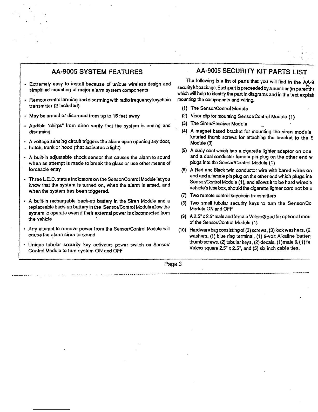
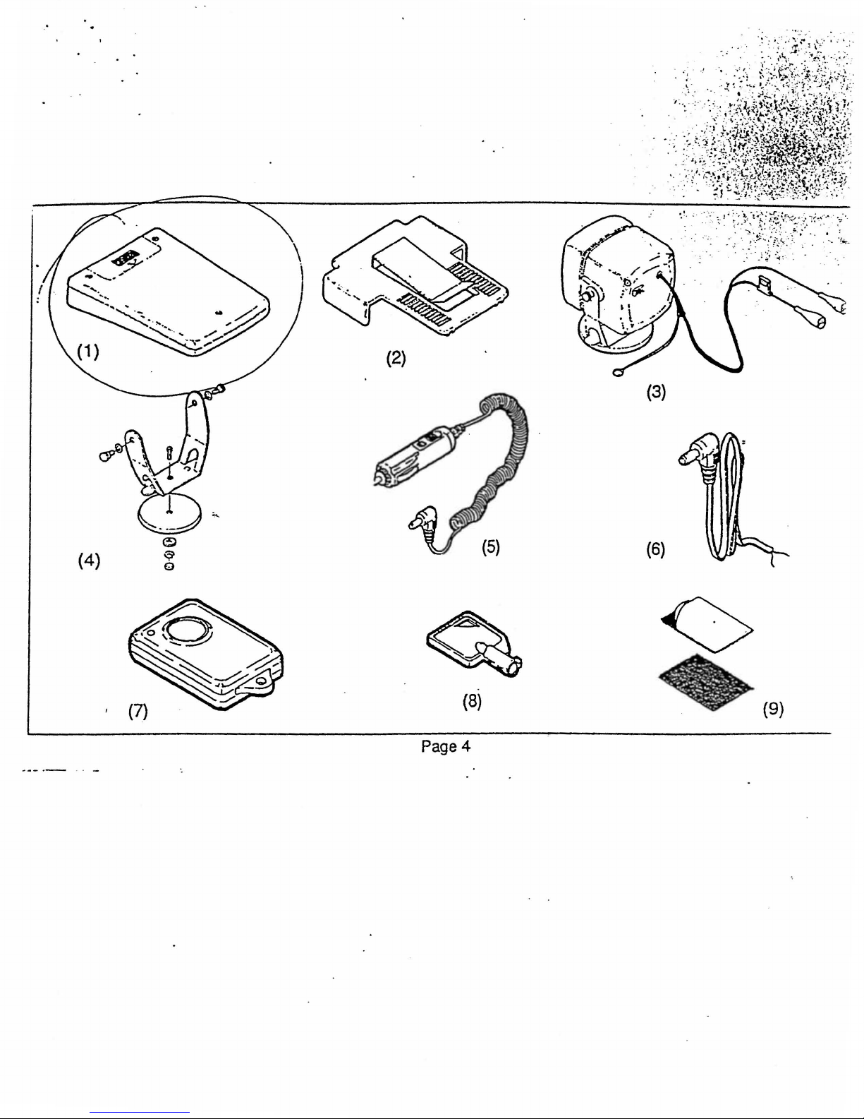
The following is a fist of parts that you will find in
security kit package. Each part
which
will help to identify the part in diagrams and in the
mounting the components and wiring.
(1)
The SensorlControl Module
(2)
VISor
cftp
for mounting Sensor/Control Module
(3)
The SirenIReceiver Module
(4)
A magnet based bracket for mounting the siren
knurfed thumb screws
Module
(5)
A curfy cord which has a cigarette lighter adaptor
and a dual condudor female pin plug on
plugs into
(6)
A Red and Black twin conductor wire with bared
end and a female pin plug on the other end which
SensOrlControl
vehicle's fuse box, should the cigarette lighter cord
(7)
Two remota control keychain transmitters
(8)
Two small tubular security keys
Module
(9) A 2.0'
of the Sensor/Control Module (1)
(10)
Hardware
washers,
thumb screws,
Velcro square
(3)
the
Sensor/Control Module (1)
ON
and
x 2.5· male and female Velcro® pad for optional mou
bag
consisting of (3) screws, (3)
(1)
blue ring terminal, (1) 9-volt Alkaline batter;
(2)
2.s- x 2.5", and (5) six
is
proceeded
for
attaching the bracket
Module (1), and allows it to
by
a number
to
tum
Off
tubular keys, (2) decals,
inCh
the
On
parenth(
text
explail
(1)
module
to
the
on
the
other
end
wires
plugs
be
hard
wired
not
the
Sensor/Co
Iockwashers.
(1
)male & (1) fe
cable ties.
~-9
S
one
w
on
intI
tt
be u
(2
Page
3
Page 5
·
(2)
(3)
Page 4
(8)
(6)
(9)
Page 6
.. •..
;J,':t'i)1y;
'.
.; .",'"
. .
:.
' .:
", (
.. :·1
".\' .
...
...
:,.
,:
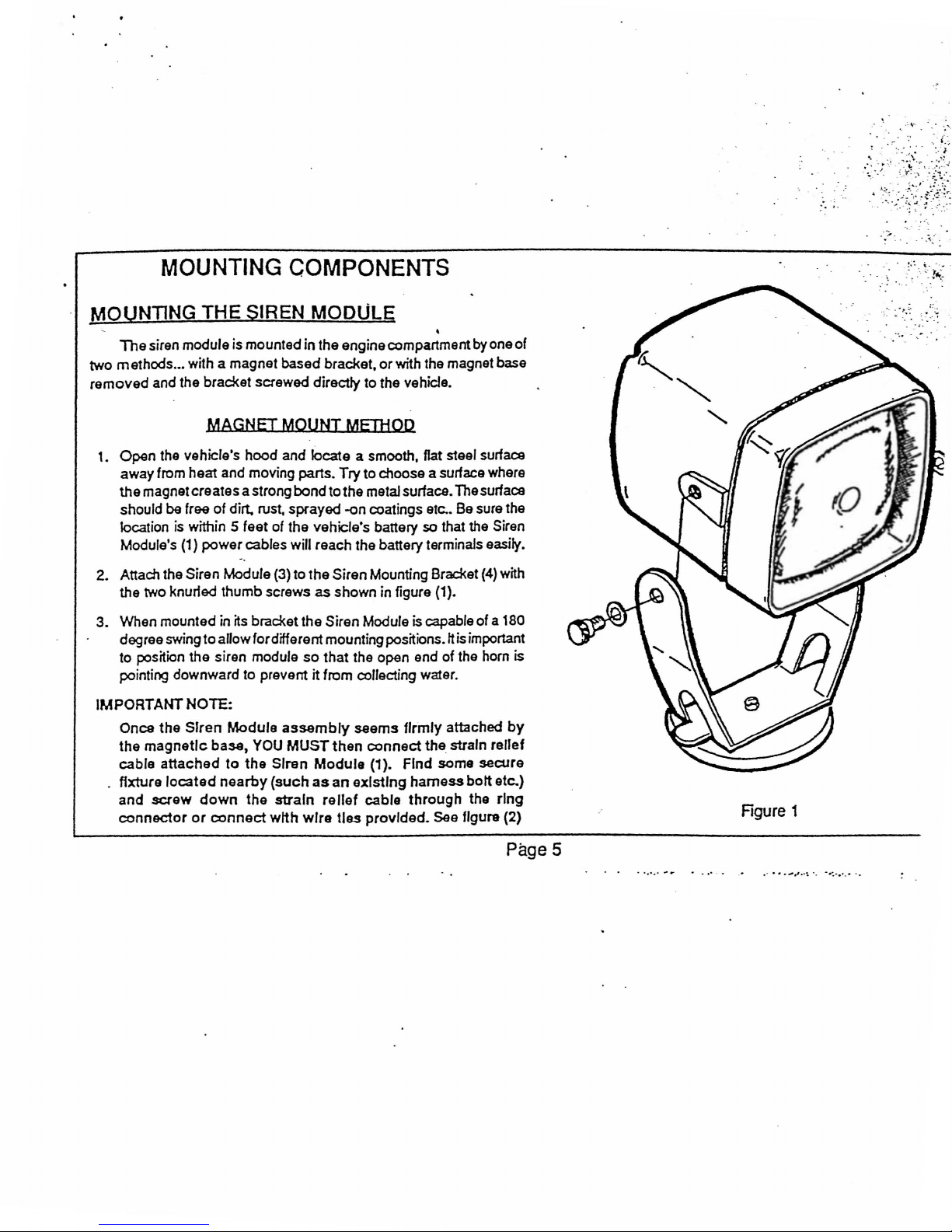
MOUNTING COMPONENTS
MOUNTING THE SIREN MODULE
The
siren module is mounted
.•.
two methods
removed
with a magnet based bracket,
and the bracket screwed directly to the vehicle.
MAGNET MOUNT
1.
Open
the vehicle's hood and locate a smooth, flat steel surfaca
away from heat and moving parts.
the
magnet creates a strong bond
should
be tree
location
Module's (1)
2. Attach the Siren Module (3) to the Siren Mounting Bracket
the two knurled thumb screws
3. When mounted in
degree swing
to position the siren module
pointing downward to prevent it from collecting water.
IMPORTANT
Once
the
the
magnetic
cable
attached
.
fixture
located
and
screw
connector
of
dirt. rust, sprayed -on coatings etc.. Be sure the
is
within 5 feet of the vehicle's battery so that the Siren
power
cables will reach the battery terminals easily.
~s
bracket the Siren Module
to
allow fordifferent mounting positions.
NOTE:
SIren
Module
base,
YOU
to
the
nearby
down
the
or
connect
in
the engine compartment
MEDiOD
Try
tothe
as shown in figure (1).
so
that the open end of the hom
assembly
MUST
Siren
(such
strain
with
wire
seems
then
ModUle (1).
as
an
existing
relief
ties
or
to choose a surface where
metal surface. The surface
connect
cable
provided.
•
with the magnet base
is
capable of a 180
It
is important
firmly
attached
the
strain
Find
some secure
harness
through
See figure (2)
by
(4)
bott
the
one of
with
is
by
relief
etc.)
ring
" \
Rgure 1
PageS
. " . .
....
.....
' .. " .. .- ." ...
....
,
..
~
.. .
..
....... .
Page 7
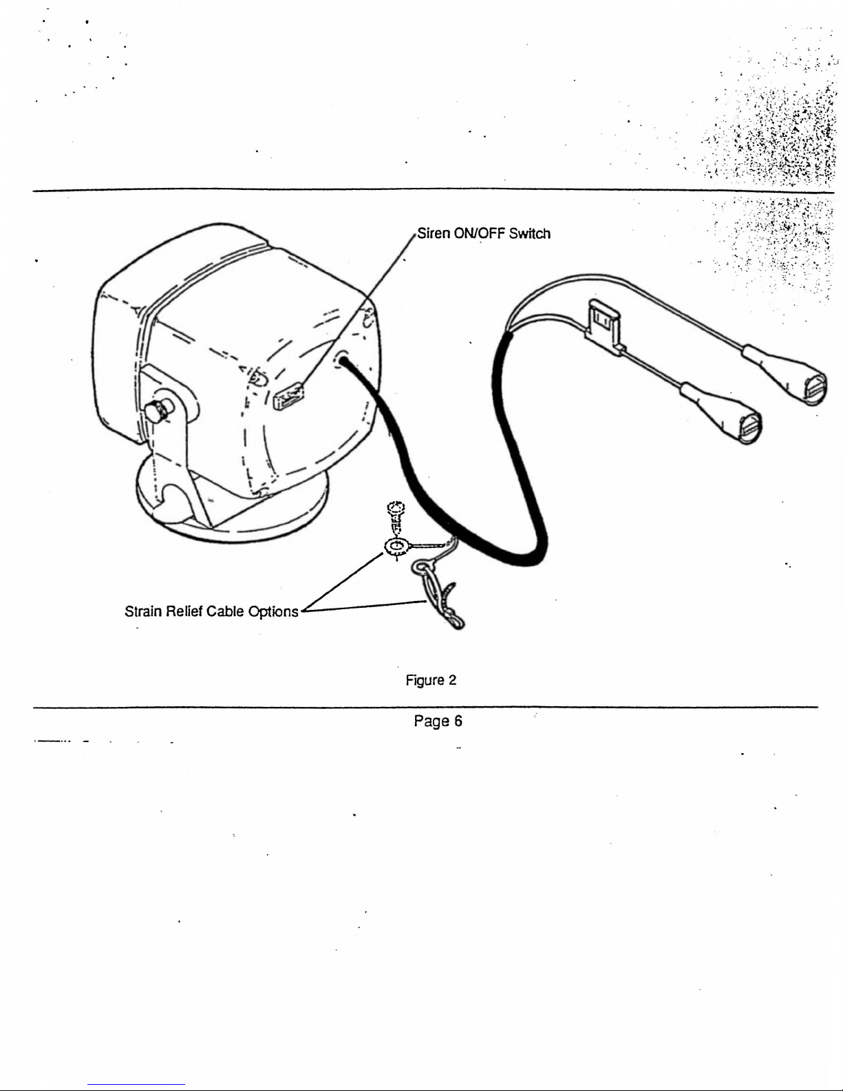
Siren
ON/OFF
Switch
;: .
.
~ .
'.'. R:'
;
i
Figure
Page
2
6
Page 8
.;
..
~.
, .
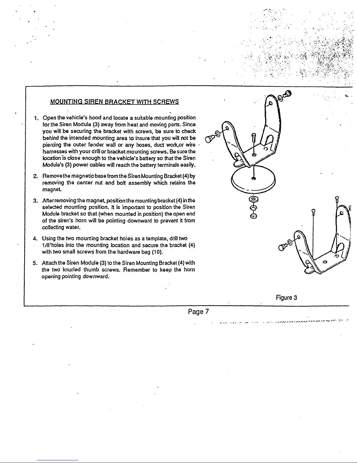
MOUNTING SIREN BRACKET
1. Open the vehicle's hood and locate a suitable mounting position
for
the Siren Module (3) away from heat
you
will
be
securing the bracket with screws,
behind the intended mounting area
piercing the outer fender wall or any hoses, duct
hamesses with
location
Module's
IS
your
dnll
or
bracket mounting screws.
close enough to the vehicle's battery so that the Siren
(3)
power
cables will reach the battery terminals easily.
Willi
SCREWS
and
moving parts. Since
be
sure to check
to
insure that you will not be
worX.or wire .
Be
sure the
2. Removethe magnetic base from the Siren Mounting Bracket (4)
removing the center nut and bolt assembly which retains the
magnet
3.
After removing the magnet. position
selected mounting position.
Module bracket so
of
the siren's horn will be pointing downward
collecting water.
4. Using the two mounting
1181101es
with
5. Attach the Siren Module (3) to the Siren Mounting Bracket
the
opening pointing downward.
into the mounting location and secure the bracket (4)
two
small screws from the hardware bag (10).
two-
knurled thumb screws. Remember to keep the horn
that
(when mounted
brac!<et
the
mounting bracket
(4)
in the
It is important to position the Siren
in
position) the open end
to
prevent it from
holes
as
a template, dnll two
(4)
with
by
Page 7
Rgure
3
Page 9

MOUNTING COMPONENTS (CONT.)
MOUNTING THE SENSOR/CONTROL MODULE
The
SensortControl Module (1)' is mounted in the vehicle's
passenger
visor
may
of
self-adhering Velcro® pads (9) supp6ed in the
recommended
sunlight
Specifications section.
compartment
dip
to
the passenger side sun-visor or alternatively the module
be
mounted directly to the canter console
to
mount this module on top
as
high temperatures may damage the unit. Refer to
It
can
be
mounted by means of a snap-on
SUN-VISOR MOUNTING METHOD
or
lower dash by means
kit.
It
of
the dash. in direct
GeneraJ
is not
1. Attach the visor mounting
by
snapping the tabs on the clip into the grooves
SensorlControl Module (1)
position the clip
(1) with the visor
of
the
module.
2.
Once
it
is
end
of
the visor clip (2) onto the passenger's side sun-visor. over
the edge of
location where you have the ability to see all three status indicator
LE.D.
keys
fights
witch
on
dip
attached to the Sensor/Control Module (1) sfide the open
the
visor closest
and
where you easily have accass to the ON/OFF
area
dip
(2) to the Sensa r/Control Module (1)
on
the sides
as
shown in figure (5).
the flat. battery compartment side of the module
opening facing toward the front (narrow end)
to
the windshield.Choose a visor
Be
of
the
sure to
Page
8
Figure
5
Page 10

~
~
.
...
.
..
. .
. ,
CONSOLE
1.
Locate the 2.5-x 2.5- Velcro® pads
2.
Stick the pads together keeping
as
possible.
3. Remove the
OR UNPER-DASH MOUNTING MEJtIOD
(9)
supplied with
all
the edges lined up as closely
protective paper from the adhesive
on
one
the
side
kit.
of the
Velcro® "sandwich-.
4.
Position and stick the Velcro®
pads
over the center of
the
flat
(battery compartment) side on the Sensor/Control Module (1). See
figure,(6)
CAUTION:
compartment
transmitter
00
not
doo.(
code
stick
or
over
numbers
the pads onto
or
over the battery
the small white labels with
on
them.
your
5. Choose a location on the console or under your dashboard where
you have the
and where you
6. Remove the protective
Velcro®pad "sandwich-still attached to
ability to see all three status indicator LED. lights
easily have accass to
paper
from
the
ON/OFF keyswitch area.
the
remaining
the
Sensor/Control Module
side
of
the
(1), and stick the module to the chosen dash location.
NOTE:
Insure
Be
sura
proper
that
the mountIng area Is clean
adhesion.
and
dry
to
Rgure 6
Page 9
Page 11

WIRING THE COMPONENTS
WIRING
. Wiring the Siren Module
1. Exiting the rear of the Siren Module (4) locate the six foot Red and
2.
3.
4.
THE
SIREN
Black twin lead with the
clamps on the end.
Route this wire toward the vehicle's 12 volt main battery, being
careful to keep it away from hot areas and moving engine parts.
possible follow existing wiring harnesses toward the battery.
It will be necessary
provided in the hardware bag
Once you have reached the battery location securely clamp the
Red clip to the
the
Black
CAUTION (1): Be sure
clips
do
terminals.
of
corrosion.
located
CAUTION
or
be
touching
(+)
dip
to the (-) negative side of the battery.
not
touch
Be
sure
on the Red wire Just
(2): Verify
MODULE
(3)
is very simple. Proceed
two
Red and Black "jumper cable-type
to
secure this wire with several cable ties
(10) in order to keep it
positive side of the battery and securely clamp
that
the
any
that
Check
any
metal
other
the
that
that
exposed
meta I surfaces
battery
there
behind
the
battery
surfaca
metal
terminals
Is
a fuse
the Red
cll
ps
will
when
the
as
follows:
in
place.
surfaces
beside the battery
are clean
In
battery
not
hood
and
the
fusholder
cllp_
be dislodged
Is
closed.
on the
free
. .
;~
.
Siren
ON/OFF
Switch
If
WIRING
There are two methods for connecting power
Module. The first and easiest is with the cigarette lighter curly
If
you do not wish to tie up the vehicle's c;igarette lighter, orthe cigarette
lighter loses power when the ignition switch is shut
have to hardwire the Sensor/Control Module
foot length
THE
SENSOR/CONTROL
of
cable supplied for this purpose (6).
MODULE
to
the Sensor/Control
cord (5).
off,
then you will
to
the fusebox with the six
Vehicle's Battery
Rgure 7
Page 10
Page 12

CIgarette
1.
Verify that the cigarette fighter operates with the ignition key
If
it
does
not, refer to hard wire method below
2.
Locate
.
3.
Plug the small female pin plug on the end of the curly cord into the
hole
See
4.
Plug the other end
lighter
the cigarette lighter curly cord (S) supplied
on
the side
of
figure (8)
of
recepticaL
lighter
Method
"OFF".
in
the kit •
the Sensor/Control Module marked DC12V.
the
curly
cord into your vehicle's cigarette
Hard Wire To Euseblock Method
1. Locate the 6 foot Red and Black twin lead with a small female pin
plug on one end and
2. Plug the small female pin plug on the end
hole on the side
See
figure (9)
3.
Leaving a small amount
route the twin lead
whenever possible behind interior trim
careful not to let the wire interfere with any moving mechanical
parts
such as vent rods, the steering mechanism, or the brake, gas
or
clutch pedals.
4.
When
you reach the fuse block
12
volt supply. (This 12 volt supply must remain
the
ignition key is in the OFF position.)
S.
Connect the Black wire
blue
ring terminal provided. Verify it's a good ground connection.
NOTE:
may
consumer.
procedure
Making
~e
beyond
If
please
two bared wires on the other
of
of
the Sensor/Control Module marked DC12V.
of
slack near the Sensor/Control Module,
end
the twin lead into the
toward the fuse block, conceanng the wire
or
under the dash. Be
conned
to
a solid metal surface using the crimp-on
the
connections
the
technical
you
have
any
consult a qualified
the Red wire
to
the
vehicle's
understanding
questions
automotive
to
a constant
'hor
even when
fuse
of
the
concerning
technlclan.
(6).
.block
average
this
. '
...
'
',:
.
Rgure 8
Rgure 9
:
:..
.. : ..
<."
•
"~:',
.'
~.
~
...
J.>~.\
..
..
,"
~.'t
..
.
"
;~
.'''
,;.:.,;..,
~:
,,.
-
..
'.
Page
11
Page 13

SYSTEM SET-UP AND ADJUSTMENTS
".< <
TuRNING
Before
;J005
the Siren Module and the Sensor/Control Module must ba turned
THE SYSTEM ON
we
can discuss the operation
and
adjustments of the
In.
fumIng
1.
2.
3.
4~
'umlng
1.
2.
3. Find
l.
On
The SIren Module
locate
Module (4).
Remove
power
Sfide
plug to prevent water retention. See figure (7)
Assuming you have made the proper connections to the vehicle's
battery as described
should now be energized.
locate
Insert the key into the security key-switch located on the Sensorl
Control Module
handy.
Assuming the Siren Module is energized you should hear
-chirp· from the siren indicating that the system has baen
You will also notica that the green
Control Module will steadily illuminate. indicating that the module
is energized.
switch is first turned on, indicating that
the protective rubber switch cover
the cover (but
switch.
the
switch to the
On
The Sensor/Control
one of the small tubular Control Module
one
of the Remote keychain transmitters (8) and keep
The
do
not discard)
ON
position and then re-insert the rubber
under.':Component Wiring" the Siren Module
Module
(1)
and
turn to the ON position. See figure (10)
LE.D.
red
LE.D. will also start flashing when the
on
the back of the Siren
to
expose the Siren Module
ON/oFF
on
the front ofthe Sensor/
the
alarm
is
armed.
M-
keys
(9).
one
armed.
key
.
5. Before continuing any further. the alarm system must be disarmed.
6.
FlOd
the remote keychain transmitter and depress the button.
7. The siren should
the Sensor/Control Module should turn off indicating that the
system is now disarmed.
ArmIng And DIsarm
You should now check the operation of each of the keychain
transmitters as follows:
1.
Exit
the vehicle making sure to close
2.
Test one keychain transmitter at a time. Depress the transmitter
button momentarily and you should hear the siren
indicating the system is armed. Press the button once again
you should hear multiple chip indicating the system is disarmed.
3. To test the
approximately 3 seconds and the siren should start
continuously. Depress the transmitter button again. The siren will
it
stop sounding and you will hear multiple chirp indicating that the
alarm is again disarmed.
4. Repeat steps 2 and 3 to test the operation of the second keychain
transmitter.
-chirp-two times and the red
Ina Test
With
The
Kevchaln
an
·Panic· feature. hold the transmitter button down
LE.D.
inoJCator
Transmftters
doors, trunk and
·chirp"
to
on
hood.
onca
and
for
sound
Page 12
Page 14

.
-,
.~
Adlustlng
in
voltage
door,
of
the
it
takes
trigger
wouldn't
current
1.
The
Voltage
One
of
the features of the
caused
trunk. hatch
SensorlControl Module (1) to adjust the level of voltage variation
to
adually
if a thief opens the
want your electric
sensor
Sit
inside the
Chad< to make sure no fights in the vehicle are illuminated.
do the following:
Sensor Sensitivity
M-9005
by
the illumination of a right bulb when opening a
or
hood. There is a sensitivity adjustment
triggerthe alarm.
door
car
with all the doors, trunk. hatch and hood closed.
For
and the dome light comes on but you
doc1<
to
set the alarm off. To adjust the
Circuit
is
~s
ability to
instance you want the alann to
mon~or
on
changes
the side
2. Locate the voltage sensor adjustment screw on the side of the
Sensor/Control Module
3.
Gently
not
4.
Arm the system with the remote keyChain transmitter (depress the
button, the siren
5.
Gently
siren
by
6.
If
voltaget sensor adjustment
clockwise, arm the system, and gently
7.
Keep
is
turn the screw counter-clockwise until you feel it stop.
force the control beyond this point!
open a
door
sounds, no further adjustments are necassary. Stop the siren
depressing the button on the keychain transmitter once again.
the
siren-does not sound, disarm the system, advance the
repealing this process until the siren sounds when the door
opened
and the dome fight illuminates.
(1). See figure (10)
will'chirp'
and verify that the dome light illuminates.
once).
SCtew
about one-eighth
open the
door
of
a turn
again.
If
Do
the
....
8.
IMPORT~
"atter-fansvoltage sensing circuitry.
must
be
a.
Shut off the Sensor/Control Mcxfule (1)
sect/r~
"wedge-side of the Module, and turn to
Unplug the power lead from the Sensor/Control
b.
remove the module from its mounted position.
c.
Loca1e
Sansor/Control Module (1) as shown in figure (12).
d.
Slide the battery compartment cover
remove the
e.
Locate the Orange wire loop in the battery
f.
Cut
this Orange wire loop to disable the voltage
g. Return the back-up battery into its
the battery compartment door.
h.
Ra-mount the Sensor/Control Mcxfule to its
re-connact the power plug,
the ON position.
NOTE: The voltage sensing
disabled
Unfortunately some vehicles also
which may trigger false alarms
by-passed
ket
the battery compartment cover
and all voltage sensing features are inoperative.
accor~ing
(8) into the security key-switch located
back-Up battery.
-
..
-
...........
If
this occurs the
to the following
and
tum the security
capability
compartment
-
..
----
with
the
voltage
on
of this
sensing
procedure:
by
inserting a tubl
the
OFF
the
"flat'" side
off
the
compartment.
sensing
original
system
...
-,,;;.~.
have
elec
M-90C
on
on
position.
Module
of
module
eire
and
rep/a
positic
key-switch
is
nc
.
c
1
a
Page
13
Page 15

••
#
'.
':
.,
.
....
.
~.
;
" .
..
··J;~1;l:·~~H~~
: r
,~~~.,'._.'tl·~::.
"'
"~-:
:,:..:~"
.
Adlustlna
1. Locate the
2.
3.
The
Shock
Sensor/Control Module (1). See figure (10)
Gently turn the screw counter-clockwise
not force the control beyond this pointl
Step outside the vechicle and
Sensor
shock sensor adjustment screw on the side
Sensitivity
dose
hood.
4. Arm the system
button, the siren will
"Power
ON" LED Indicator
with
the remote keychain transmitter (depress the
"chirp- once).
Control
unt~
you feel
all
doors, trunk. hatch
it
stop.
oJ
the
Do
and
~
'.
~
,:.
. .
S.
With
the open palm of your hand
windshield pillar
if
the
siren sounds.
are
necessary. Stop the siren
keychain transmitter once again.
6.
If
the
siren does not sound,disarm the system. advance
sensor adjustment screw about one-eighth of a turn clockwis
.
arm
the system, and repeat step 5 once again.
Keep
7.
repeating this process until the siren sounds
vehide is struck with a sharp blow.
or
bumperofthe vehide (neverthe glass)
lithe
siren does sound no further adjustmen
derIVer
by
depressing the button
a sharp
, .:,
blow
the
when
Security ON/OFF Keyswitch
"Armed" LED Indicator
.~.~;
.:-
..
~:.
....
• . "
"f~
to-
11",
and
s€
on
tt
she<
tt
Figure
10
Page
14
Shock Sensor Adjustmer,
Voltage Sensor
Adjustment
Page 16

AA-9005 SYSTEM OPERATION
'"
.......
_----------
.
"".~
'.
'"
'
Arming
1.
The
System
Exit the vehicle and
dose
all
doors, trunk. hatch and hood.
2. Depress the button on your remote keychain transmitter and
observe the following:
a. The siren will "chirp· once to give
that the system is armed.
you
an audible confirmation
b. The red LE.D. on the front of the Sensor/Control Module will
to flash, indicating that the system is armed.
begin
Disarming
Upon
1.
keychain
a.
b.
Using
1.
The
in the
2.
To
your
the siren begins to sound.
3.
To
keychain transmitter button. The siren will stop sounding and chirp
to
The
System
retuming to the vehicle
transmitte~
The
siren will
that the system has been disarmed.
The
red
LE.D. on the front
bUnking,
stop
The
Remote PanIc
panic feature will operate regardless of whether the alarm is
armed-mode
activate the remote panic mode simply hold down the button on
remote keychain transmitterfor approximately 3 seconds until
deactivate the remote panic mode momentanly depress the
let
you know the system is disarmed.
and observe the following:
"chirp"
indicating the system is disarmed.
or
the disarmed mode.
~epress
to give you an audible confirmation
of
E$atu(f~
the button on your remote
the Sensor/Control Module will
Attempted Break-In IndIcator
1.
!he
M-900S
• In your absence. _
2.
Upon returning to your vehicle do not disarm the system beft
checking
SensoriControl Module. H the yellow
that the
wlll let you
the status
alarm was triggered in your absence.
know
LE.D.
if
a force able entry was attemp'
indicator lights
LE.D.
is flashing it indica
on
the face
of
Y'
3. lheflashingyellowindicatoriscancenedwhentheunitisdisarm
Remoylng
the Sensor/Control Module have internal back-up batteries that '
allow the system to
from the vehide's main power source. To shut the system power off
servicing or to disconnect power cables, procaed
1. Disarm the system with the remote keychain transmitter.
2.
3. Insert the key into the security key-switch located on the
4.
?ower
To
prevent tampering with the system both the Siren
Locate one of the two small tubular security power keys (8).
Control Module
NOTE: If
desalbed
from either the cigarette lighter
the alarm
It with
your
!tis now okay to remove the SensoriControl Module's powerplu
And Shutting
work
even if the major components are disconnec
(1)
and tum
you
fall
to
above, when you attemptto remove
will
activate and the siren
remote keychaJn transmitter).
The
System Down
to
the OFF position. See figure
disarm the Sensor/Control
or
the Siren/Control Mod;
will
sound!
as
follows:
the
Module,
Module
power
(You
Sen~
can
51
<-
p~
Page
15
Page 17

_
...............
...
AA-9005 BACK-UP BATTERY SYSTEMS
DESCRIPTIONS
& REPLACEMENT
PROCEDURES
SIren Module Built-In Back-yp Battery
The Siren Module (3) has a built-in, rechargable back-up battery that
3110ws
the system to function and the siren to sound,
'saches
This built-in battery.
;ource
This battery
s
up under the hood and disconnects the siren's battery clips.
re-charges directly from the vehicle's main power
and has been designed for manyyears
is not consumer replaceable.
not
operational consult your dealer
of
dependable operation.
If
you suspedthatthis battery
or
authorized warranty station.
even
if
a thief
[ransmltter
f
the
ransminer; or
ransminer becomes
ransminer's battery as follows:
1. Unsnap the transmitter cover at the end
using a coin
2. Install a new
marks etched in the batlery area of the transmitter.
Battery Replacement
alarm system does not activate or. disarm when using the
if
operation becomes erratic;
weak
or
goes
out
or
flat blade.
1-2
volt Type
GP23A
or
if
the small light
then you will have
opp::Jsite
battery noting the
on
the
to
replace the
the keychain,
(+)
and (-)
3. Replace the transmitter cover using care not to damage the small
red LED.
Page 16
Rgure
11
Page 18

~nS9r
Your Sensor/Control Module
battery. This battery allows the system
power
external power source.
Control Module
is
removed from the Sensor/Control Module
Battery
(1)
Replacement
has a built-in. replaceable 9 volt
to
remain operational even if the
by
unplugging its
9
Volt
Alkaline
" y
Battery
NOTE: Cara
Module
from
the
thIs
Is
To
replace the transmitter's battery proceed
Shut off the Sensor/Control Module
1.
security ket (8) into the
side of the Module.
2.
Unplug the power lead from the SensortControl Module
remove the module from its mounted position.
3. Locate the battery compartment cover
Sensor/Control Module (1) as shown in
4. Slide
the
5. Replace
6. Return the
battery compartment door.
7.
Ra-mount the Sensor/Control Module
conn
position.
must
be taken
with
the
tubular
vehlcla's maIn
not
dona
the
back-up 9 volt
the
battery compartment cover off the module and remove
bacl<-up
battery.
t.he
old battery with a new alkaline 9-volt battery.
bacl<-up
ect
the power plug. and turn the security key-switch
to
tum
"OFF" tha Sensor/Control
security
power
a"nd
battery into
key
(8)
Ifthe
module
source
security key-switch located on the "wedge"
tum to the OFF position.
or
removed for
batteryw/ll
as
(1)
on
flQure
its
compartment
to
draIn
follows:
by
inserting a tubular
the "flat" side of the
(12).
its original pashion, ra-
Is
unplugged
storage.lf-
quickly!
and
replace the
to
and
the ON
Figure
Orange
12
Wire
Loop
Ins
Page 17
Page 19

•
>'
::"
••
....
___
._
.. _ ......................
.,
..........
_
.. _ ........
_
.......
.-
...........
_
..... _ .............
___
............
a'
•••••
AA-9005 TROUBLESHOOTING
You
falls
does
You
falls
does
depress
to
chirp
not
Indicate
Rgure
13
depress
to
chirp
Indicate
the
a(ld
the
btit
that
Problem
remote
the
that
remote
the
the
transmitter
Sensor/Control
the
transmttter
Sensor/Control
alarm
alann
has
has
button
been
button
Module's
anned.
Module's
armed.
but
and
.
the
the
red
red
siren
LED
siren
LED
PossibleSolution
Verifythatthe power switch on both the Sensor/Control Module
and'the Siren Module are turned on. Check that the Sensor/
Control Module's green power indicator light is nJurninated. If it
is not, cheCk the
or
the hard wire cord) at both ends to be sure it is
proper connection. Also check the 1 amp fuse located inside
the cigarette fighter adaptor plug by unscrewing the
plug
assembly
Module loses contact with your vehicle's
extended length of time, and the system ison, it
internal, 9-volt battery and the system will cease
Another possibility is that the remote transmitter's battery is
weak or dead. Try
experience the same problem. Referto page 15 forTransrnitter
Battery Replacement instructions. .
Open the vehicle's hood and verify that there
electrical connection between the vehicle's battery
and the clips supplying power to the Siren Module.
the Siren Module's Power switch is in the "ON" position. Chec!
to see that the red clip is on the positive (+) terminal and thr
black
Clip
is
in-line with the red power wire (located just behind the
battery cfip) leading to the Siren Module, to be sure it i
operational.
12
volt supply cable (either the cigarette lighter
as
shown in figure (13). If the Sensor/Control
your
on the negative
12
volt
supply
will
second transmitter and
(-)
tenninal. Check the 4
making
front
to
function.
see
is
of
for
drain
if you
a solie
the
the
any
the
terininal~
Verify
amp
tha
fus:
r91
Page
18
Page 20

You
experIence
....
· .
..........
..........
.........
-
.........................................
--_
...
_
..
-........ -
AA-9005 TROUBLESHOOTING
Problem Possible$olution
multiple, unexplaInable false alarms The most likely cause of false alarms in this
from the vehicle's electrical system creating a
drop due
electrical device drawing a sufficient amount
trigger the voltage sensing circuit Refer to
#8
to
Another
sensitivity
page 13's section
Sensitivity Control.
to
an atter-fan cooling system
correct this problem.
reason
for false alanns is that the
is
set too high. To correct this problem
on
Adjusting the
Shock
............................
...
system
or
some
of
page
shock
OCCl
voltag
OthE
current
13
iter
senS{
refer
Sensor
.
1
1
Alarm
every
seems
time
you
to arm
shut
or
trigger
the
Itself
Ignltlon
erratIcally and/or
~ey
off.
Whenever
with the vehicle'S main power supply it autornatical
triggers if armed, or arms itself if disarmed.
main power source
where the power cord plugs into the module,
power cord makes its connection to the vehicle's
source (either the cigarette lighter or the fuse
you may find that your vehicle's lig hter socket
volt supply when the ignition key is turned
the module to be hard wired to the fuse
page11).
Page 19
the
Sensor/Control Module (1)
can
be caused
by a poor
loses
Loss
where
block).
loses
off
requirir
block
conta
of
tt
conta
it
consta
its
(Sl
.
Page 21

AUDIOVOX'S 12 MONTH LIMITED WARRANTY
Applies to sirens, sensor modules, hoodlocks and detection modules.
AUDIOVOX CORPORATION (the Company) warrants
or
any part thereof, under normal use and service, be proven defective in material
date
of
original purchase, such defect (s) will
labor.
To obtain repair
(e.g. dated bill of sale), transportation prepaid,
warranty does
This
alteration, improper installation, mishandling, misuse,
This warranty is in lieu of all other express warranties or liabilitiesANY IMPLIED
WARRANTY
ACTION FOR BREACH
MUST
BE
COMPANY BE LIABLE FOR ANY CONSEQUENnAL OR INCIDENTAL DAMAGES FOR BREACH OF THIS OR ANY OTHER
WARRANTY, EXPRESS
any liability
Some states do not allow limitations
. consequential damage
This warranty gives you specific legal rights and you may also have other rights which vary from state
IN EASTERN U.S.A.: AUDIOVOX CORPORATION,
IN WESTERN U.S.A.: AUDIOVOX WEST CORPORATION, 16808 MARQUARDT AVENUE, CERRITOS, CAUFORNIA 90701,
(213)
926-n58
IN CANADA: AUDIOVOX CANADA LTD., 1070 KAMATO ROAD, UNIT
(416)
629-1400
or
replacement within the terms of this warranty, the product is
not
apply
to
any product
OF MERCHANTABIUTY, SHALL
BROUGHT WITHIN A PERIOD OF 30 MONTHS FROM DATE OF ORIGINAL PURCHASE.
other
OF
ANY WARRANTY HEREUNDER INCLUDING ANY IMPUED WARRANTY OF MERCHANTABILITY
OR
than expressed herein in connection with the sale of this product
IMPUED, WHATSOEVER.
so
the above limitations
be
to
or
on
how long an implied warranty lasts or the exclusion or limitation of incidental or
to
the original retail purchaser
repaired
an
part thereof which in the opinion of the Company has been damaged through
BE
or
or
replaced (at the Company's option) without charge for parts and
approved warranty station or the Company at the address shown below.
neglect. or accident.
UMITED
exclusions may not apply
60
TO
THE DURATION OF THIS WRITTEN WARRANTY.
No
person
or
representative is authorized to assume for the Company
to
ARKAY DRIVE, HAUPPAUGE, NEW YORK 11788, (516)
15,
MISSISSAUGA, ONTARIO, CANADA, L4W-2WS,
of
this product that should this product
or
workmanship within 12 months from the
to
be
delivered with proof of warranty coverage
WARRANTIES, INCLUDING ANY IMPLIED
IN
NO CASE SHALL
you.
to
state.
231..Q051
ANY
THE
Page 20
Page 22

·
.,..
~
.......
~
.......
~
......... -............ , .....
~--
..
-
....
'"
1.
RF
GENERAL
SECTION:
SPECIFICATIONS
Range:
Keychain
Sensor/Control
transmitter
Module
to
Sensor/Control
to
Siren
Frequency:
Keychain
Sensor/Control
2. RECHARGEABLE (SIREN) BATTERY:
Battery
rife
with
In
trigger
In
standby
Recharging
3.
REPLACEABLE (SENSOR/CONTROL MODULE)
Battery
4.
CURRENT DRAIN IN
Siren
life
with
Module:
Sensor/Control
transmitter
main
mode:
mode:
time:
power
mlGGER
12ma
maximum
Module:
to
Sensor/Control
Module
power
to
Siren
disconnected:
3.5
to 4 hours
25
to
30
4
to 5 hours
disconnected: 8 to
MODE:
on
fully
30ma
maximum
Module:
Module: 3 Meters
Module:
Module:
310
hours
ALKALINE
10
hours
charged
back-up
5 Meters
418
MHz
SA
battery
MHz
TTERY:
5. OPERAT1NG TEMPERATURES:
Sensor/Control
Siren
Module:
Module:
85° C maximum
85° C maximum
~age
21
Page 23

bottom
Module
have
that
below
your
parts
·
(battery
(1)
a different
you
record
and
side
of
only
link
for
your
compartment
you
will
Code
number
these
on
the
tear
this
page.
to
ordering
specific
AA-900S IMPORTANT CODE·NUMBERS
If
you
look
on
the
your
Sensor/Control
stickers.
it.
numbers
card
numbers
transmitters or
It
is
on
each
will
Important
on
the
chart
the
opposite
will
be
repair
side) of
find
three
printed
three
different
-out
wallet size
These
replacement
alarm
system.
white
on
code
TRANSMIlTER
SENSOR/CONTROL
SECURITY
ONiOFF
Page
CODE
NUMBER
MODULE
KEY
22
NUMBER
NUMBER
Page 24

'.
.""
.r:....
.
....
Audiovox Corporation • 150 Marcus Boulevard • Hauppauge,
NY
11788
 Loading...