

Audio Technica BP24 User Manual

Studio Broadcast System
bp24 SET UP and USE
Studio Broadcast System
1. REGULATORY AND COMPLIANCE STATEMENTS ............................................................................................................ 3
2. OVERVIEW
2.1 Core Performance Targets
2.2 Specifications
2.3 System Components
2.4 System Block Diagram
3. BP24 UWB BODY PACK TRANSMITTER ...........................................................................................................................
4. RP32 UWB RECEIVER MODULE .......................................................................................................................................
5. MCU3224 MAIN CONTROL UNIT .....................................................................................................................................
4.1. FRONT PANEL ...........................................................................................................................................................................................
4.2. REAR PANEL .............................................................................................................................................................................................
6. GUI INTERFACE ...............................................................................................................................................................
5.1. HOME SCREEN ..........................................................................................................................................................................................
5.2. TRANSMITTER DETAIL SCREEN ......................................................................................................................................................................
5.3. MATRIX SCREEN - RECEIVER MEASUREMENT ...................................................................................................................................................
5.4. MATRIX SCREEN – TRANSMITTER MEASUREMENT .............................................................................................................................................
5.5. SETUP SCREEN ..........................................................................................................................................................................................
7. QUICK START ...............................................................................................................................................................
Page 2 of 26
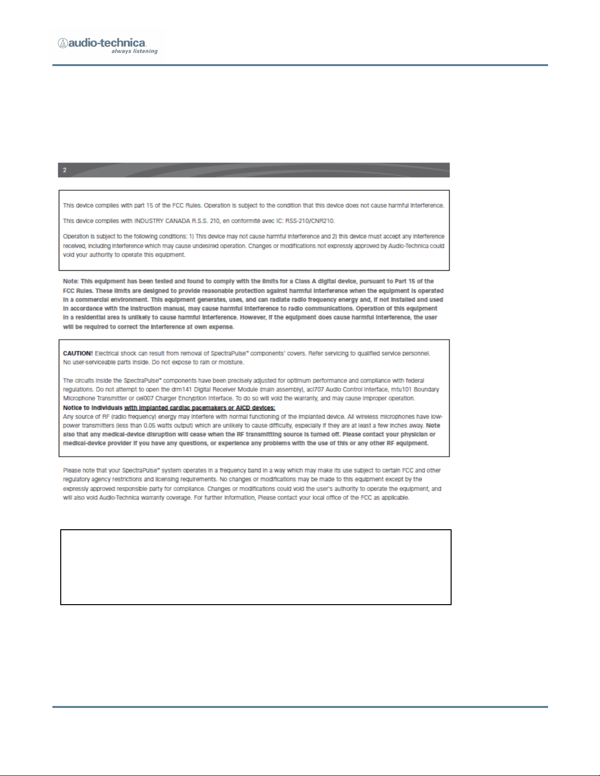
STATIC HAZARD. Opening this unit is likely to cause permanent performance
malfunction. Evidence of opening will void warranty. Serviceable only by
Audio-Technica. Contact Audio-Technica for return authorization should
service be necessary.
1. REGULATORY AND COMPLIANCE
Studio Broadcast System
Page 3 of 26
STUDIO BROADCAST
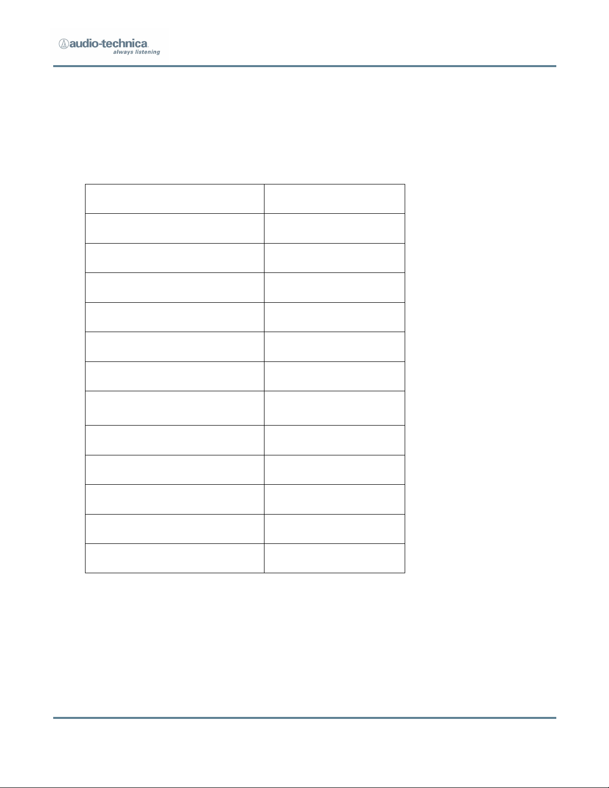
Operating Method
UWB OOK
Center frequency
6.500GHz
Simultaneous Receive Points
32
Simultaneous Transmitters
24
Audio Dynamic Range
24 bits
Frequency Response
20Hz -20kHz
Latency
<3 mS
Analog to Digital out
Audio Interface
MADI/DANTE
External Control Interface
USB/Ethernet
User Interface
Touchscreen GUI
Battery Life
5 hours
Range (single RP line of sight)
90 feet
2. Overview
2.1 Core Performance Targets
Studio Broadcast System
Page 4 of 26
Overall System
Dynamic Range
>109 dB (A-weighted, typical)
Total Harmonic Distortion
<0.06% (-40dBV input level)
BP24 Specs (inherent to beltpack /
Direct connect
Self Noise @ 0dB gain
-111dBA
Self Noise @ 20dB gain
-106dBA
Sensitivity @ 0dB gain
-44dBV
Sensitivity @ 20dB gain
-23dBV
Dynamic Range
111dB (A-weighted, typical)
SNR @ 0dB gain
67dBA
SNR @ 20 dB gain
82dBA
Maximum Input Level (5% THD)
4.8dBV
Total Harmonic Distortion
<0.06% (-40dBV input level)
Operating Frequency Range
6250MHz – 6750MHz
Tx Output Power
2nW mean
Modulation
none
Emissions Designator
500MN1W
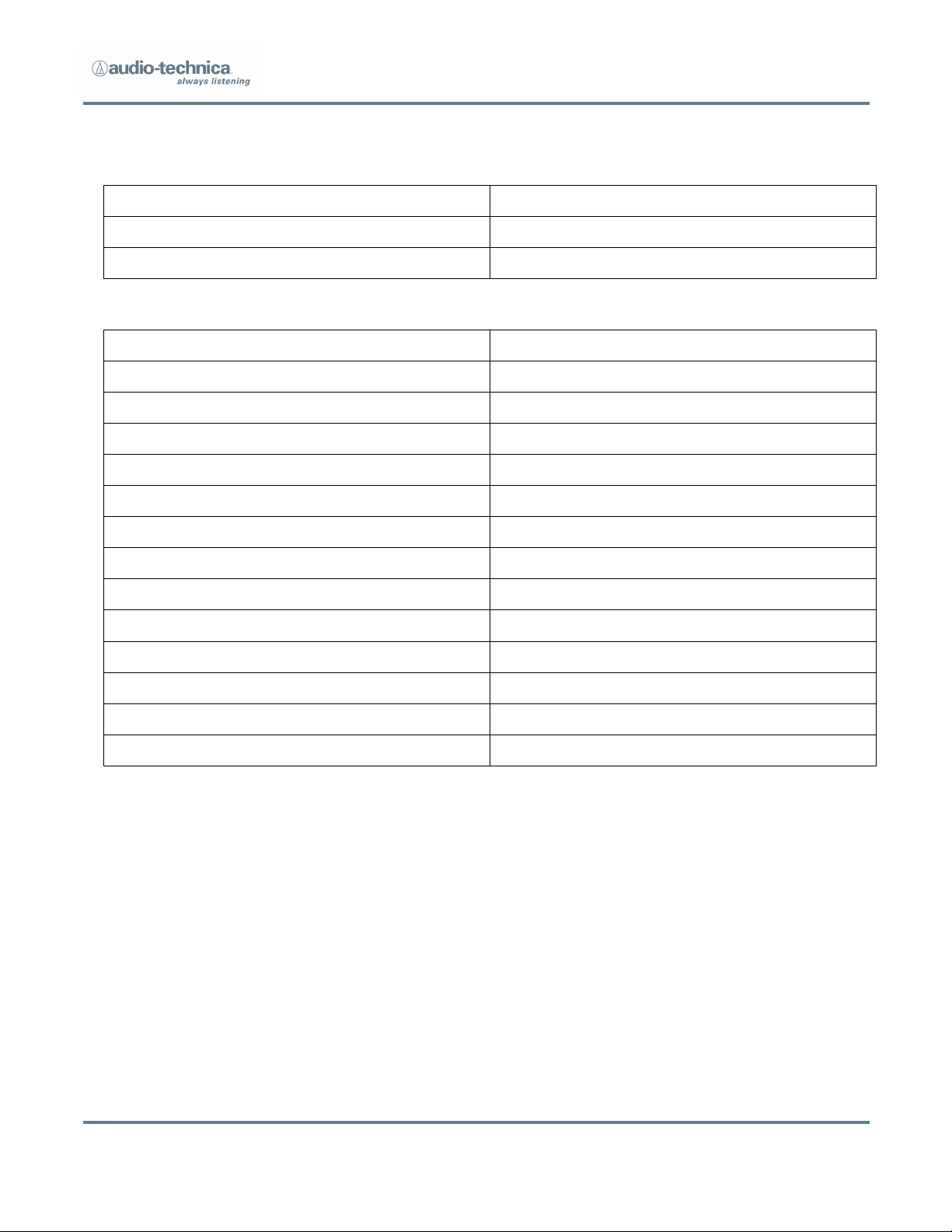
2.2 Specifications
Studio Broadcast System
Page 5 of 26
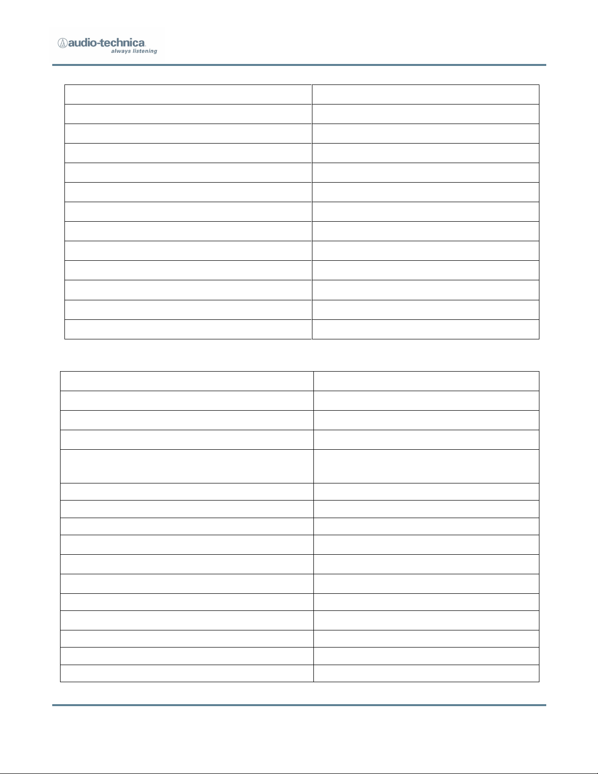
Studio Broadcast System
BP24 w/ AT899cL4 or cL4SW mic
Self-Noise @ 0dB gain
-109dBA
Self-Noise @ 20dB gain
-93dBA
Sensitivity @ 0dB gain
-48dBV
Sensitivity @ 20dB gain
-28dBV
Dynamic Range
109dB (A-weighted, typical)
SNR @ 0dB gain
61dBA
SNR @ 20dB gain
65dBA
Frequency Response
20Hz – 20,000Hz
Impedance
250 ohms
DC current
1.7mA
Battery
2 x AA
Battery life
5 hours
MCU3224
Frequency Response
20Hz – 20,000Hz
Input/Output Connections
MADI
2 x 75 ohm BNC to coax, 2 x
multimode fiber
DANTE
2 x RJ45
Receivers
32 x 12 V, RJ45
Black burst
1 x BNC
Headphone/Monitor Out
@ 33 ohm load
Total Harmonic Distortion
<0.1%
Noise
-90dBV
Maximum Output Power
200mW
Power
Redundant AC supply
2 x 110-240V, 50-50Hz, 420W max
Cable
2 x IEC
Page 6 of 26
Model
Description
BP24
Body Pack Transmitter with Talkback Function
RP32
UWB Receiver and Antenna Module
MCU3224
Main Control Interface Unit (3U)
AT899cL4 or
cL4SW
Microphone
Microphone with Inline Talkback Switch
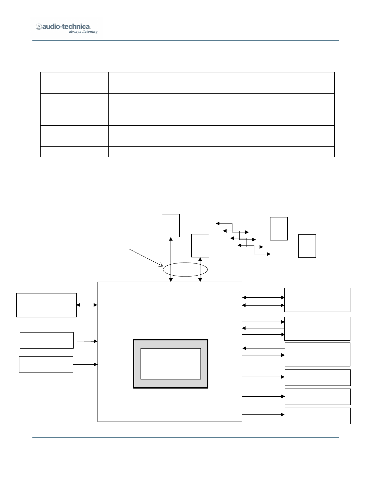
MAIN CONTROL INTERFACE UNIT
(3U)
TX
1
. . .
TX
24 RX1
RX
32
. . .
Wireless Links
(TDMA)
Cat 5 - All RX Home Run to Main
Control Unit
. . .
Mains In (Red)
Mains In (Blue)
Network Control
(Future) Ethernet
Network Audio
Dante
BNC-Audio
Word Clock In
Word Clock Out
MADI
75Ω co-ax
MADI
Fiber (GBIC)
Fiber Out
Audio CH 1-8
7” TOUCH SCREEN
GUI
(on-board)
FUTURE Analog Break Out
FUTURE Analog Break Out
FUTURE Analog Break Out
Dante 1
Dante 2
Audio CH 9-16
Audio CH 17-24
x24
x32
Fiber In
2.3 System Components
2.4 System Block Diagram
Studio Broadcast System
`
Page 7 of 26

Studio Broadcast System
3 BP24 UWB Body Pack Transmitter
3.1 Transmitter Controls
An On/Off power switch is located in the battery compartment.
The adjustable transmitter parameters are:
1. System ID (SYS) – Each transmitter must be assigned a system ID (1-9) that
must match the system ID set on the MCU3224
The transmitter will only transmit when it receives a sync pulse and
matching system ID from an active system. This will prevent users with
transmitters assigned the same channel slot on a different system from
interfering if they enter the coverage area.
Note: RP timing signals from separate systems must be RF isolated from
one another to prevent system timing contention in transmitters.
2. Channel Number (CHAN) – The channel slot assigned to the transmitter (01-
24.) Each transmitter in the system is assigned a unique channel number.
3. Input level (GAIN) – Adjustment of the audio input level (0 dB to 20dB in
2dB Steps).
The adjustable transmitter parameters are shown on a display located on the face
of the transmitter.
The display will only be illuminated when the user is adjusting the transmitter.
Pressing any button will activate the display for 10 seconds. After 10 seconds,
display functions will no longer be illuminated although the BP is functioning.
Pressing any button will light the display in order to check for power or operating
condition.
Page 8 of 26
 Loading...