

Page 1
3000 Series
User Manual
UHF Wireless Systems
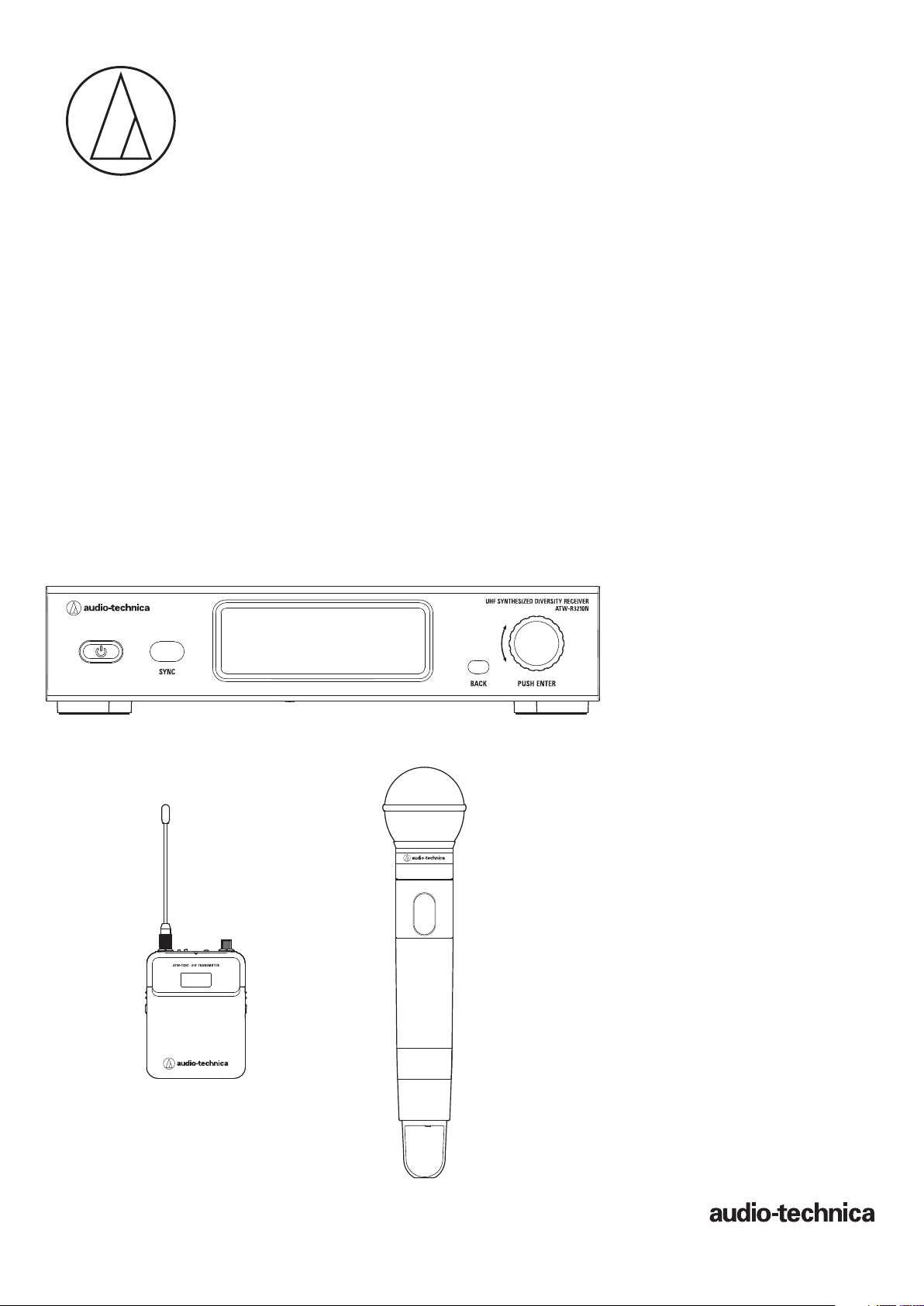
ATW-R3210N
Receiver
ATW-T3201
Body-Pack Transmitter
ATW-T3202
Handheld Transmitter
Page 2

Contents
Introduction .................................................................................2
Important information .................................................................2
Notes on use ...............................................................................3
Maintenance ................................................................................3
Part names and functions ............................................................4
ATW-R3210N ................................................................................................... 4
ATW-T3201 ...................................................................................................... 6
ATW-T3202 ...................................................................................................... 7
How to insert batteries ................................................................8
ATW-T3201 ...................................................................................................... 8
ATW-T3202 ...................................................................................................... 8
How to attach and detach the interchangeable microphone
capsule (only for ATW-T3202) ......................................................9
How to attach ................................................................................................. 9
How to remove ............................................................................................... 9
How to read the display ............................................................10
ATW-R3210N ................................................................................................. 10
ATW-T3201/ATW-T3202 ................................................................................. 12
Network .....................................................................................13
What is Wireless Manager? .......................................................................... 13
How to operate ..........................................................................14
Basic operation ............................................................................................. 14
Using IR SYNC .............................................................................................. 14
Settings .....................................................................................15
ATW-R3210N ................................................................................................. 15
ATW-T3201/ATW-T3202 ................................................................................. 15
Setting ATW-R3210N .................................................................16
List of setting items ...................................................................................... 16
Setting the operating frequency .................................................................. 16
Setting the channel (receiver) name ............................................................. 16
Setting the audio output level ....................................................................... 17
Scanning for open channels ......................................................................... 17
Setting transmitters via IR SYNC ................................................................. 17
Setting the squelch level ............................................................................... 18
Setting the system-related functions ............................................................ 18
Setting network ............................................................................................. 21
Setting ATW-T3201/ATW-T3202 .................................................23
List of setting items ...................................................................................... 23
Setting the transmission frequency .............................................................. 23
Setting the channel (transmitter) name ........................................................ 23
Setting the gain ............................................................................................. 24
Setting the RF transmission output .............................................................. 24
Setting HPF (High-Pass Filter) ....................................................................... 24
Setting lock ................................................................................................... 24
Setting the function for the function button ................................................. 24
Setting the mute mode (only for ATW-T3201) .............................................. 25
Setting the system-related functions ............................................................ 25
How to attach the transmitter (ATW-T3201) .............................27
Making connections (basic connections) ..................................27
Achieving stable reception ........................................................28
Rack-mounting the receiver.......................................................28
Troubleshooting .........................................................................29
ATW-R3210N ................................................................................................. 29
ATW-T3201/ATW-T3202 ................................................................................. 29
Dimensions ................................................................................30
ATW-R3210N ................................................................................................. 30
ATW-T3201 .................................................................................................... 31
ATW-T3202 .................................................................................................... 31
Specifications ............................................................................32
Overall system specifications........................................................................ 32
ATW-R3210N ................................................................................................. 32
ATW-T3201 .................................................................................................... 32
ATW-T3202 .................................................................................................... 33
1
Page 3

Introduction
Thank you for purchasing this Audio-Technica product.
Before using the product, read through this user manual to ensure that you will use the product correctly. Please keep this manual for future
reference.
Important information
Warning:
• To prevent fire or shock hazard, do not expose this apparatus to rain or
moisture.
Caution:
• Do not expose this apparatus to drips or splashes.
• To avoid electric shock, do not open the cabinet.
• Refer servicing to qualified personnel only.
• Do not expose this apparatus to excessive heat such as that generated
by sunshine, fire or other heat sources.
• Do not subject this apparatus to strong impact.
• This apparatus should be located close enough to the AC outlet so
that you can easily grasp the AC adapter at any time.
• In case of emergency, disconnect the AC adapter quickly.
• Do not place any objects filled with liquids, such as vases, on this
apparatus.
• To prevent fire, do not place any naked flame sources (such as
lighted candles) on this apparatus.
• Do not install this apparatus in a confined space such as a bookcase
or similar unit.
• Install this apparatus only in the places with good ventilation.
• The rating label is put on the bottom of this apparatus.
Battery caution:
• Keep batteries out of the reach of children.
• Observe correct polarity as marked.
• Do not expose the battery to excessive heat such as sunshine, fire or
the like.
• Always consider the environment issues and follow local
regulations when disposing of batteries.
• Remove depleted battery immediately.
• Danger of explosion if battery is incorrectly replaced. Replace only
with the same or equivalent type.
• Use only disposable LR06(AA) alkaline or NiMH batteries.
• Do not use new batteries and old one at the same time.
• Do not use different battery types or models.
• Do not use a leaking battery. If battery leakage occurs, avoid
contact with skin. If contact occurs, immediately wash thoroughly
with soap and water.
• If battery leakage comes into contact with your eyes, immediately
flush with water and seek medical attention.
For customers in the USA
FCC Notice
Warning:
This device complies with Part 15 of the FCC Rules. Operation is
subject to the following two conditions: (1) This device may not cause
harmful interference, and (2) this device must accept any interference
received, including interference that may cause undesired operation.
Caution:
You are cautioned that any changes or modifications not expressly
approved in this manual could void your authority to operate this
equipment.
Note: This equipment has been tested and found to comply with
the limits for a Class B digital device, pursuant to part 15 of the FCC
Rules. These limits are designed to provide reasonable protection
against harmful interference in a residential installation. This equipment
generates, uses and can radiate radio frequency energy and, if not
installed and used in accordance with the instructions, may cause
harmful interference to radio communications. However, there is no
guarantee that interference will not occur in a particular installation. If
this equipment does cause harmful interference to radio or television
reception, which can be determined by turning the equipment off and
on, the user is encouraged to try to correct the interference by one or
more of the following measures:
- Reorient or relocate the receiving antenna.
- Increase the separation between the equipment and receiver.
- Connect the equipment into an outlet on a circuit different from that
to which the receiver is connected.
- Consult the dealer or an experienced radio/TV technician for help.
For customers in Canada
IC statement
CAN RSS-Gen/CNR-Gen
This device complies with INDUSTRY CANADA R.S.S. 210. Operation
is subject to the following conditions: (1) This device may not cause
harmful interference and (2) this device must accept any interference
received, including interference which may cause undesired operation.
This device complies with RSS-102 radiation exposure limits set forth
for an uncontrolled environment.
2
Page 4

Notes on use
• Be sure to read the user manual for any microphone or cable that you attach to the product.
• Disconnect the AC adapter from the outlet when this product is not in use.
• Turn off the power of this product before connecting or disconnecting cables.
• If you use the product near a TV or radio antenna, you may hear unwanted noise in the television or radio. If this occurs, move the product away
from the device.
• Two waves of the same frequency can't be used simultaneously.
• Be careful of interference noise caused by the surrounding radio wave environment and use of multiple systems.
• Wireless systems may be affected by the spark noise of vehicles, dimmer of lighting apparatus, computers, office automation apparatus and
electronic musical instruments. Place and use the product where it is less likely to be affected by the above.
• Be sure to use this product in combination with components specified by our company.
• Be sure to use a general-purpose LAN that complies with the Ethernet standard (CAT5e or higher, with shielding is recommended).
• Disconnect the LAN cable when not using the network.
• Be sure the connected cable is plugged all the way into the product.
• When you connect the product with a mixer, turn off the phantom power source.
• If you use the product close to an electronic or communications device (such as a mobile phone), the product may produce unwanted noise. If
this occurs, move the product away from the device.
• When setting up the product, make sure there are no obstacles between the transmitter and the receiver that might block the signal.
• To prevent the batteries from wearing out, turn the transmitter off when not in use.
• Over time, discoloration may occur due to ultraviolet rays (especially direct sunlight) and friction.
• It is legally prohibited to dismantle and modify this product. In addition, this product is so precisely manufactured that dismantling it could cause
electric shock, failure or fire. Never dismantle this product.
Using multiple wireless systems
• If you use more than one device at the same time, use them in the same group.
• When using multiple units simultaneously, maintain 1 meter or more between individual transmitters and 3 meters or more between transmitters
and receivers' antennas.
• When using multiple units, power on transmitters one by one, making sure there is no unwanted noise.
• When a howling (beeping or squealing) sound is produced during use, turn down the output volume of the connected mixer/amplifier.
Maintenance
• If the product becomes stained or covered with dust, be sure to disconnect the power plug before wiping it off with a dry and soft cloth.
• Do not use benzine, thinner or electrical contact cleaner, etc. They may deform or otherwise damage the product, or cause operational failure.
3
Page 5
Part names and functions
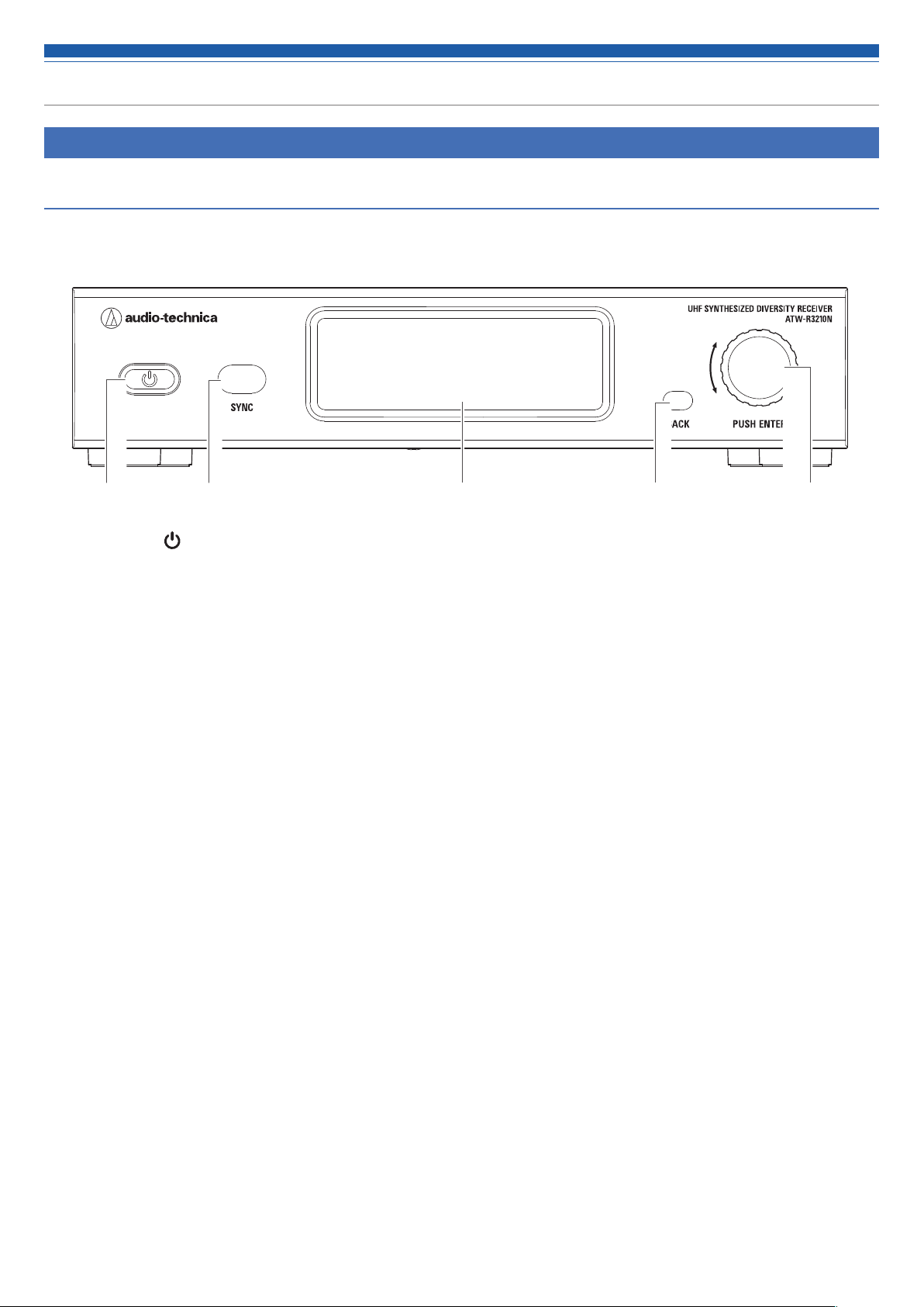
ATW-R3210N
Front panel
❷❶ ❹ ❺❸
❶ Power button ( )
Use to turn the receiver on or off.
❷ IR sync window
Use to IR SYNC with the transmitter (ATW-T3201, ATW-T3202).
❸ Display
Displays the receiver state and setting menus.
❹ BACK button
Press to take the display back one screen.
Returns to the Main screen when pressed and held.
❺ Control dial
Switches the screen when you turn the dial.
Displays the setting menu when you press the dial. Turn the dial to select a setting and press to confirm.
When you press and hold the dial, QUICK SYNC is started.
4
Page 6
Part names and functions
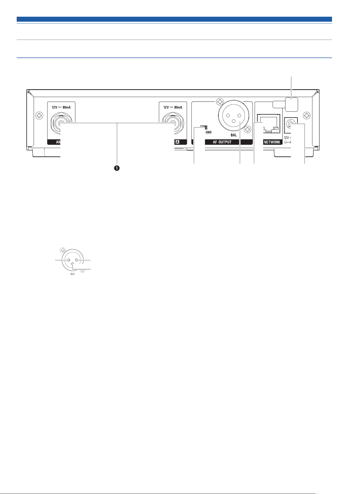
Rear panel
❻
❶
❶ Antenna input jack
Each jack supplies DC12 V to a connected antenna.
Additionally other compatible accessories (sold separately) can be connected.
❷ Ground lift switch
This switch isolates the GND pin of the balanced/unbalanced output from the ground.
Normally this is kept in the GND position, but if a hum develops due to a ground loop, switch to the LIFT side.
❸ Balanced output jack
(XLR 3-pin male)
GND
HOT
COLD
❹ Network interface
By connecting to a PC via Ethernet, you can use the PC for monitoring and control.
LAN : 100Base-TX
❺ DC input terminal
Connect DC plug from the included AC adapter.
❻ AC adapter cord hook
Hang the power cord of the AC adapter to prevent it from pulling loose accidentally.
❺❸❷ ❹
5
Page 7
Part names and functions
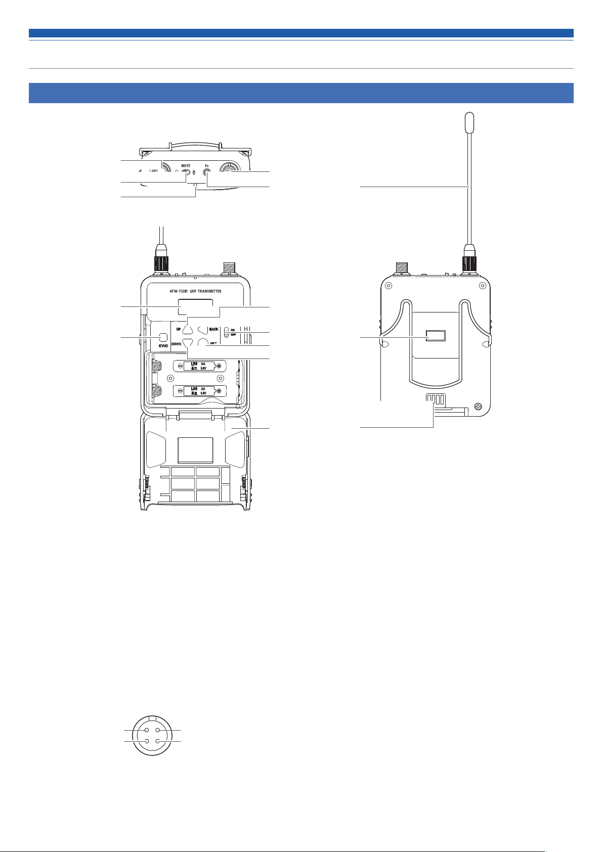
ATW-T3201
❶
❷
❸
❺
❹
❶
❻
❼
❶ Transmission antenna
❷ MUTE switch
Switches audio mute on and off.
❸ Indicator
LED that shows the status of the transmitter.
When the power is turned ON: Solid green
When the transmitter is muted: Solid red
❹ Function button
Press briefly to turn the screen back on if it shuts off. Press and
hold to perform preselected function.
❺ Input connector
Connect a microphone, a headworn microphone, a guitar cable, etc.
Pin 1: GND Pin 4: +5 V output
Pin 2: Instrument input Pin 3: Microphone input
❻ Display
Shows the current status.
If no buttons are pressed for a period of 30 seconds, the display
will turn off.
❽
❾
❿
⓫
⓬
⓭
⓮
⓯
❼ SYNC button
Use to IR SYNC with the receiver (ATW-R3210N).
❽ UP button
Use to select various settings.
❾ BACK button
Press to return to the previous screen.
Returns to the Main screen when pressed and held.
❿ Power switch
Use to turn the power on or off.
⓫ SET button
Press to confirm a selection.
⓬ DOWN button
Use to select various settings.
⓭ Battery cover
⓮ IR sync window
Use to IR SYNC with the receiver (ATW-R3210N).
⓯ Charging terminal
6
Page 8
Part names and functions
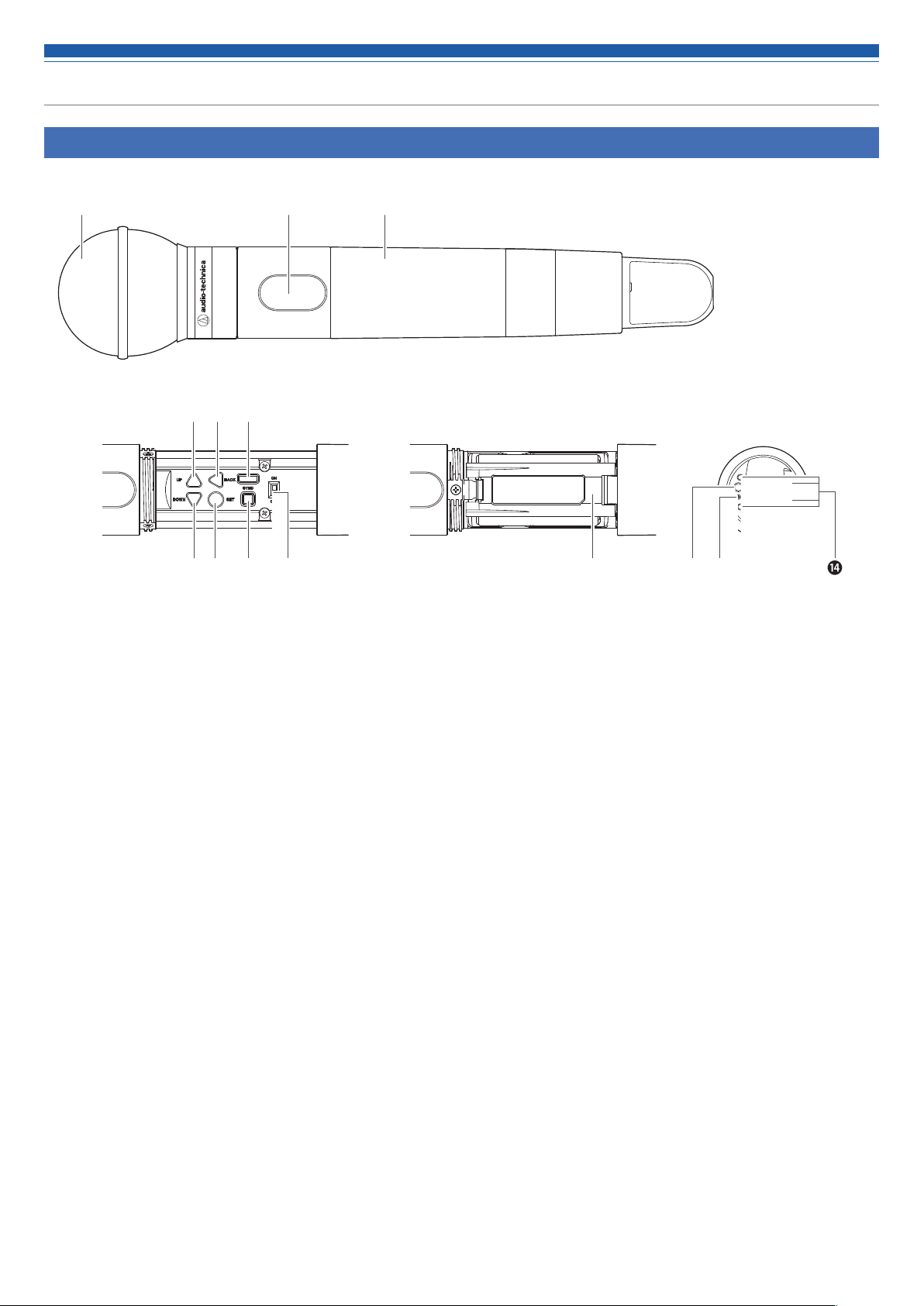
ATW-T3202
❹ ❺ ❻
❸❷❶
❼ ❽ ❾ ❿ ⓬ ⓮⓭
❶ Interchangeable microphone capsule
❷ Display
Shows the current status.
If no buttons are pressed for a period of 30 seconds, the display
will turn off.
❸ Grip case
❹ UP button
Use to select various settings.
❺ BACK button
Press to return to the previous screen.
Returns to the Main screen when pressed and held.
❻ IR sync window
Use to IR SYNC with the receiver (ATW-R3210N).
❼ DOWN button
Use to select various settings.
❽ SET button
Press to confirm a selection.
⓫
❾ SYNC button
Use to IR SYNC with the receiver (ATW-R3210N).
❿ Power switch
Use to turn the power on or off.
⓫ Battery cover
⓬ Function button
Press to turn the screen back on if it shuts off. Press and hold to
perform preselected function.
⓭ Indicator
LED that shows the status of the transmitter.
When the power is turned ON: Solid green
When the transmitter is muted: Solid red
⓮ Charging terminal
7
Page 9
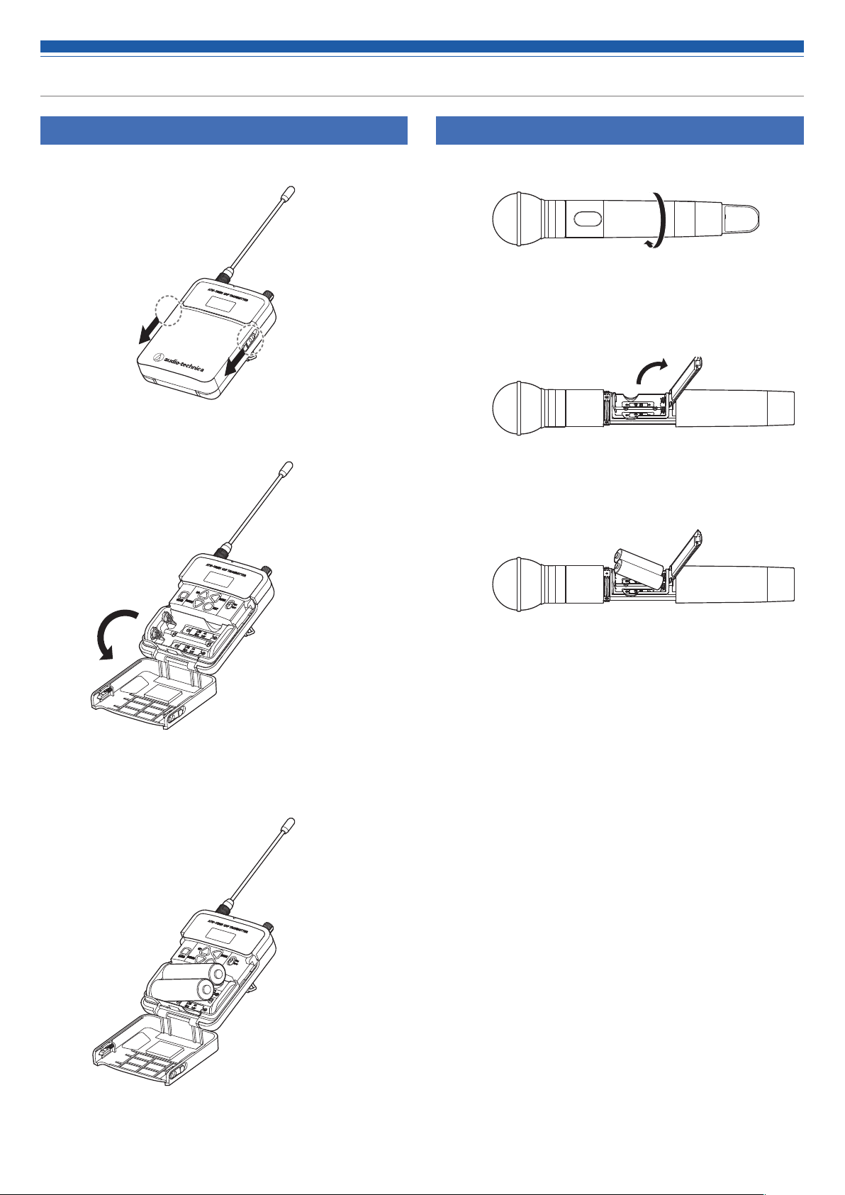
How to insert batteries
ATW-T3201
1. Slide the battery cover latches down.
2. Open the battery cover while the latches are slid.
ATW-T3202
1. Rotate the grip case of the battery compartment.
2. Open the battery cover.
• Put your finger on the hook of the battery cover and pull it to open the
battery cover.
3. Insert the batteries according to the plus (+) and minus (-) marks
found inside the battery compartment.
3. Insert the batteries according to the plus (+) and minus (-) marks
found inside the battery compartment.
8
Page 10
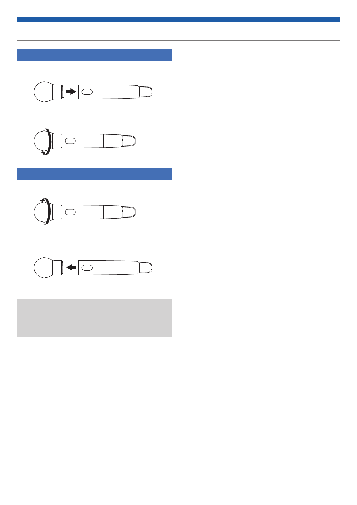
How to attach and detach the interchangeable microphone capsule (only for ATW-T3202)
How to attach
1. Attach the microphone capsule to the body of the transmitter.
2. Rotate the microphone capsule clockwise to tighten it.
How to remove
1. Rotate the microphone capsule counterclockwise to loosen it.
2. Detach the microphone capsule from the body of the
transmitter.
• Do not directly touch or scratch the connection surface.
• Be sure to turn off the power of the transmitter before attaching/
detaching the microphone capsule.
• Do not forcibly attach the microphone capsule. Doing so may damage
the transmitter or microphone capsule.
9
Page 11
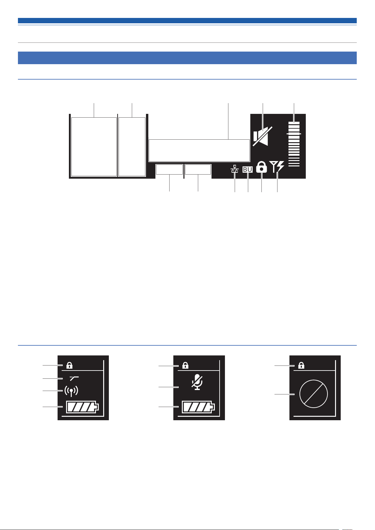
How to read the display
ATW-R3210N
Main screen
❶
TX
HPF
❷ ❸ ❹ ❺ ❻
B
A
30mW
RF AF
❶ Transmitter information display area
Information on the connected transmitter is displayed. Refer to
"Transmitter information display area" (p. 10) for screen display.
❷ RF level indicator
Displays the strength of RF reception for antennas A and B.
❸ Name display
Displays the specified name.
❹ Frequency indicator
Displays the set frequency.
❺ Receiver mute indicator
A speaker icon with a slash through it is displayed when the
receiver is muted.
❻ AF level indicator
Displays the strength of the received audio signal.
VOCAL1
000.000
G:00 C:00
❼ ❽ ❿❾ ⓫ ⓬
❼ Group indicator
❽ Channel indicator
❾ Network indicator
Icon is displayed when the receiver is connected to a network.
❿ Backup frequency indicator
"BU" icon is displayed when the backup frequency mode is ON.
⓫ Lock status indicator
⓬ Antenna input power indicator
Icon is displayed when the antenna power supply is ON.
MHz
BU
0
Transmitter information display area
❶
❷
❸
❹
❶ Lock status indicator
❷ High-pass filter indicator
❸ RF transmission output indicator
TX
HPF
30mW
Normal Muted Non-communication
❶
❺
❹
TX
MUTE
❹ Battery level indicator
❺ Transmitter mute indicator
A microphone with a slash through it is displayed when the
transmitter is muted.
❻ Transmitter non-communication indicator
10
❶
❻
TX
Page 12

How to read the display
Level meter screen
❶
RF
TX-RF PWR
30
mW
12 dB
TX
10 dB
RX
A
B
AF
❸ ❹ ❺
❶ RF transmission output indicator (transmitter)
❷ Marker (when the minimum hold function is on)
Shows the minimum level at which the RF is held.
❸ Mute indicator
A speaker icon with a slash through it is displayed when
transmitter is muted.
❷
-92
-40 -30 -24 -18 -15 -12 -10 -8 -6 -4 -2 0 +2 +4 +6 dBu
-86 -80 -74 dBm
OL
❹ Audio output indicator (receiver)
❺ Gain indicator (transmitter)
❻ Overload (excessive input) indicator
❻
Minimum hold function
If you press the BACK button on the level meter screen, the minimum hold function turns on and its marker is displayed.
• The marker indicates the lowest level of RF signal received from the transmitter.
• The marker does not move if the input RF level is higher than the marker position.
• If the RF level input is lower than the marker position, the marker moves in tandem with the RF level.
• To reset the marker position, press the BACK button again.
Switching between screens
The screen is switched every time the control dial is rotated right or left.
TX
HPF
30mW
B
A
VOCAL1
000.000
RF AF
G:00 C:00
Main screen
MHz
BU
0
RF
AF
TX-RF PWR
TX
RX
30
mW
12 dB
10 dB
A
B
-92
-40 -30 -24 -18 -15 -12-10 -8 -6 -4 -2 0 +2 +4 +6 dBu
Level meter screen
-86 -80 -74 dBm
OL
11
Page 13

How to read the display
HPF
HPF
ATW-T3201/ATW-T3202
The main screen is displayed when the power is switched on. If you press the UP/Down button on the main screen, the screen display is switched.
❶
000.000
❷ ❷❸ ❸❸❹ ❹❹❺ ❺
MHz
VOCAL1
❷ ❺
❶ Frequency indicator
Displays the set frequency.
❷ Lock status indicator
❻ ❼ ❽
Gr:00 Ch:00
❹ RF transmission output indicator
: RF Power High (30 mW)
: RF Power Low (10 mW)
RF
OFF
: RF Power Off
❸ Battery level indicator
: 75% or more battery power remaining.
: 50 to 75% battery power remaining.
: 25 to 50% battery power remaining.
: 25% or less battery power remaining.
(Flicker): Replace the batteries.
❺ High-pass filter indicator
❻ Name display
Displays the specified name.
❼ Group indicator
❽ Channel indicator
HPF
12
Page 14

Network
By connecting a receiver to a Windows PC/Mac, you can monitor and control the status of the receivers and the transmitters using a dedicated
application, Wireless Manager.
What is Wireless Manager?
Wireless Manager is software that supports the setup, control, and monitoring of compatible Audio-Technica wireless devices. It allows the user to
configure settings in the Device List tab, RF planning in the Frequency Coordination tab and keep track of critical system levels and alerts in the
monitor tab. When linked to a compatible receiver, you can scan the RF environment, monitor connected devices, and view the system log.
• Read the user manual for any device used with this software.
• Before using Wireless Manager, update network settings as described in “Setting network” (p. 21).
Router Wireless Manager
13
Page 15

How to operate
Basic operation
1. Turn on the power button of the receiver (ATW-R3210N).
• The display lights and the main screen is displayed.
2. Set the operating frequency.
3. Turn on the power switch of the transmitter (ATW-T3201/ATWT3202).
• The indicator lights and the display shows the main screen.
ATW-T3201 ATW-T3202
Using IR SYNC
This function allows you to make settings on the receiver that are
specified for the transmitter.
1. When IR SYNC is initiated on the receiver, the “Communication
in standby” screen is displayed.
2. Position the IR sync windows of the receiver and transmitter so
they face each other.
ATW-T3201
ATW-T3202
4. Set the transmission frequency.
5. Check the RF level indicator on the receiver.
• Check that antenna A or B lights up.
6. Speak into the microphone.
• Make sure the AF level indicator lights up on the receiver.
• Hold down the DOWN button of the transmitter while turning on the
power switch to start up with the RF output in the OFF state (RF OFF
mode).
3. Press the SYNC button on the transmitter.
• Wait several seconds until communication is established.
4. When the SYNC is complete, the “completed” screen is
displayed.
• The settings made on the receiver are automatically synced to the
transmitter.
• If an error occurs in the SYNC process, an error screen opens and then
the display returns to the menu screen. Check the IR SYNC windows of
the receiver and transmitter and then SYNC again.
• To cancel the SYNC process, press the BACK button on the receiver. You
will be returned to the previous screen.
Using QUICK SYNC
SYNC shortcut allows you to easily move to the settings screen where
you can configure the transmitter settings from the receiver.
1. Press and hold the control dial on the main screen for
approximately 2 seconds.
2. “TX SYNC” setting screen is displayed.
• Refer to "Setting transmitters via IR SYNC" (p. 17) for subsequent
steps.
14
Page 16

Settings
Various settings can be made from the menu screen shown on the
display.
ATW-R3210N
1. Press the control dial.
• The main menu screen appears.
2. Turn the control dial to select the item you wish to set.
B
HPF
A
VOCAL1
000.000
RF AF
G:00 C:00
UTILITIES
FREQUENCY
MHz
NAME
BU
0
TX
30mW
3. Press the control dial to open the settings menu of the selected
item.
• Press the BACK button to go back one screen.
• To cancel partway through making a setting, press the BACK button.
• While on the settings screen, the display will return to the main screen if
approximately 60 seconds pass without a button or the control dial being
used.
ATW-T3201/ATW-T3202
1. Press the SET button.
• The menu screen appears.
ATW-T3201 ATW-T3202
2. Press the UP/DOWN button to select the item you wish to set.
FREQUENCY
000
Selected
menu item
3. Press the SET button to display the settings screen for the
selected item.
• Press the BACK button to go back one screen.
• To cancel partway through making a setting, press the BACK button.
• While on the settings screen, the display will return to the main screen if
approximately 30 seconds pass without a button being used.
.000
MHz
Current setting value
15
Page 17

Setting ATW-R3210N
List of setting items
FREQUENCY MANUAL Set the operating frequency.
Gr/Ch
NAME Set the channel name.
AUDIO Set the audio output level.
GROUP SCAN Scan for open channels.
TX SYNC Set transmitters via IR SYNC.
SQUELCH AUTO Set the squelch level.
MANUAL
UTILITIES LOCK Set this function to prevent the
receiver settings from being changed.
ANT PWR Set whether to turn power on or off
to the antenna input terminals.
Gr/Ch EDIT Edit the channel allocation for user
groups (U1 and U2).
BACKUP
FREQ
DISPLAY Set the item prominently displayed at
AF METER Switch the level meter on the main
BRIGHTNESS Set the display brightness.
ACCESS Set the user access level.
RESET This returns the receiver settings to
VERSION This function displays product
NETWORK DEVICE ID Set the receiver's ID No.
IP SETTING Set the IP.
REMOTE
CTRL
SYSLOG Set whether to send the log message
DISCOVERY Set automatic detection by the
NTP Set the NTP (Network Time Protocol).
MAC
ADDRESS
Set the backup frequency.
the center of the main screen.
screen between receiver and
transmitter.
their factory defaults.
information such as the version of the
receiver.
Set the remote control.
to the Syslog server.
application.
Display the MAC address.
Setting by group/channel
1. From the menu screen, turn the control dial, select
[FREQUENCY] and then press the control dial.
2. Select [Gr/Ch] and press the control dial.
3. Turn the control dial to set the group. When finished setting it,
press the control dial.
4. Turn the control dial to set the channel. When finished setting it,
press the control dial.
• The setting is complete.
Setting the channel (receiver) name
The following characters can be entered:
• The maximum number of characters that can be entered is 8.
Alphabetic (uppercase
letters)
Symbols (+, −, #, &, period)
1. From the menu screen, turn the control dial, select [NAME] and
then press the control dial.
2. Turn the control dial, select the desired character and then press
the control dial.
• The character is input and the cursor moves.
3. Repeat the operation in Step 2 to enter all characters.
4. Turn the control dial, select [End] and then press the control
dial.
• The setting is complete.
Numeric
Space
Setting the operating frequency
Manual setting
1. From the menu screen, turn the control dial, select
[FREQUENCY] and then press the control dial.
2. Select [MANUAL] and press the control dial.
3. Turn the control dial to set the first 3 digits. When finished
setting them, press the control dial.
4. Turn the control dial to set the last 3 digits. When finished
setting them, press the control dial.
• The setting is complete.
16
Page 18

Setting ATW-R3210N
Setting the audio output level
1. From the menu screen, turn the control dial, select [AUDIO] and
then press the control dial.
2. Turn the control dial to set the audio output level.
• The level changes 2 dB +/- each time you turn the control dial.
• It can be set from -60 to 0 dB.
3. Press the control dial.
• The setting is complete.
Scanning for open channels
Scan for unused channels in the current environment for use.
1. From the menu screen, turn the control dial, select [GROUP
SCAN] and then press the control dial.
2. Turn the control dial to select the group you want to scan. After
selecting a group, press the control dial.
3. Turn the control dial to select the preferred threshold. After
selecting the threshold, press the control dial.
• You can select [Normal], [High] or [Low] sensitivity.
High: Prioritize the number of channels.
Setting transmitters via IR SYNC
This function allows you to make transmitter settings on the receiver
and then automatically configure the transmitter via IR SYNC. The
following are the available settings and setting values:
Settings Setting values
Freq Current setting value, NoChange
Name Current setting value, NoChange
RF Pwr Low:10mW, High:30mW, NoChange
Gain -10 to +20dB, NoChange
Lock Lock, Unlock, NoChange
Batt Alkaline, Ni-MH, NoChange
HPF OFF, ON, NoChange
1. From the menu screen, turn the control dial, select [TX SYNC]
and then press the control dial.
2. Turn the control dial to select a setting you would like to sync to
the transmitter and then press the control dial.
3. Turn the control dial to select the setting value and then press
the control dial.
4. Repeat Steps 2 and 3 for each setting you would like to sync to
the transmitter.
Normal
Low: Prioritize stable operation.
• Scan starts.
4. Confirm the scan result by selecting [OK] and then pressing the
control dial.
• If you want to scan over again, select [Retry].
5. Available channels and frequencies are shown in a list. Turn the
control dial, select an available channel and then press the
control dial.
• The setting is complete.
5. Turn the control dial, select [SYNC START] and then press the
control dial.
• Communication function is in standby.
Refer to "Using IR SYNC" (p. 14) for subsequent steps.
17
Page 19

Setting ATW-R3210N
Setting the squelch level
Setting automatically
1. From the menu screen, turn the control dial, select [SQUELCH]
and then press the control dial.
2. Turn the control dial, select [AUTO] and then press the control
dial.
3. Turn the control dial, select [Normal], [High] or [Low] and then
press the control dial.
• You can select one from [Normal], [High] or [Low].
High: Prioritize the sound/voice quality.
Normal
Low: Prioritize the available range.
• If an error message is displayed, change the operating frequency. The
error indicates that the current frequency is already in use or that there is
excessive noise.
• Scan starts.
Setting the system-related functions
Setting the lock
Set this function to prevent the receiver settings from being changed.
• The default setting is [Unlock].
1. From the menu screen, turn the control dial, select [UTILITIES]
and then press the control dial.
2. Turn the control dial, select [LOCK] and then press the control
dial.
3. Turn the control dial to select [Lock] or [Unlock], and then press
the control dial.
• The setting is complete.
Setting the antenna power
Set whether to turn power on or off to the antenna input terminals.
• The default setting is [Off].
• If set to [On], power is supplied to both antennas A and B.
1. From the menu screen, turn the control dial, select [UTILITIES]
and then press the control dial.
4. The scan result is shown. Press the control dial.
• The setting is complete.
Setting manually
1. From the menu screen, turn the control dial, select [SQUELCH]
and then press the control dial.
2. Turn the control dial, select [MANUAL] and then press the
control dial.
3. Turn the control dial to select the value you wish to set.
• The meter indicates the RF level.
• It can be set from levels 1 to 13.
• While the available range of the transmitter becomes wider as the
squelch level is lower, there may be cases when noises occur under the
influence of other radio waves. While the available range of the
transmitter becomes narrower as the squelch level is made higher, noises
are less likely to occur due to the less influence of other radio waves.
4. Press the control dial.
• The setting is complete.
2. Turn the control dial, select [ANT PWR] and then press the
control dial.
3. Turn the control dial, select [On] or [Off] and then press the
control dial.
• The setting is complete.
18
Page 20

Setting ATW-R3210N
Setting group/channel editing
Setting group/channel
Aside from the ten preset groups, there are two additional user-defined
scan groups: U1 and U2. Both U1 and U2 can be edited with up to 32
frequencies.
• All channels are vacant in the initial state.
1. From the menu screen, turn the control dial, select [UTILITIES]
and then press the control dial.
2. Turn the control dial, select [Gr/Ch EDIT] and then press the
control dial.
3. Turn the control dial, select [EDIT] and then press the control
dial.
4. Turn the control dial, select a group and then press the control
dial.
5. Turn the control dial, select a channel and then press the control
dial.
6. Turn the control dial, select [SET] or [RESET] and then press the
control dial.
• By pressing [SET], you can set the frequency of the selected channel.
• If you press [RESET], the frequency of the selected channel becomes
blank.
7. After setting all channels, turn the control dial, select [Sync] or
[Save] and then press the control dial.
• If you press [Save], the setting is completed.
• If you press [Sync], the screen turns to an IR SYNC standby screen. Refer
to "Using IR SYNC" (p. 14) for subsequent steps.
Syncing the Group/Channel
The U1 or U2 Groups/Channels that have been set, as outlined above,
can be sent to the transmitter via IR SYNC.
Setting the backup frequency mode
If you set the backup frequency in advance, you can switch the
frequency of the transmitter and receiver with the transmitter. It is
convenient to set this function when you want to switch the frequency
easily.
• The default setting is [Off].
1. From the menu screen, turn the control dial, select [UTILITIES]
and then press the control dial.
2. Turn the control dial, select [BACKUP FREQ] and then press the
control dial.
3. Turn the control dial, select [On] and then press the control dial.
4. Turn the control dial, select [Manual] or [Gr/Ch] and then press
the control dial.
• If you select [Manual], you can set the frequency.
• If you select [Gr/Ch], you can set the group/channel.
5. After setting each item, turn the control dial, select [Set] or
[Sync] and then press the control dial.
• If you press [SET], the setting is completed but you must still sync the
setting with the transmitter or set the backup frequency manually on the
transmitter in order to use the backup frequency.
• If you press [Sync], the screen turns to an IR SYNC standby screen.
Execute IR SYNC.
• After IR SYNC is complete, the transmitter's function button switches to
"Bkup Freq". (p. 24).
Setting the layout of the main screen
Select the item to be prominently displayed at the center of the main
screen.
• The default setting is [Frequency].
1. From the menu screen, turn the control dial, select [UTILITIES]
and then press the control dial.
1. From the menu screen, turn the control dial, select [UTILITIES]
and then press the control dial.
2. Turn the control dial, select [Gr/Ch EDIT] and then press the
control dial.
3. Turn the control dial, select [Gr/Ch SYNC] and then press the
control dial.
4. Turn the control dial to select group and then press the control
dial.
• The screen turns to an IR SYNC standby screen. Refer to "Using IR
SYNC" (p. 14) for subsequent steps.
2. Turn the control dial, select [DISPLAY] and then press the
control dial.
3. Turn the control dial, select [Frequency] or [Name] or [Gr/Ch]
and then press the control dial.
• The setting is complete.
19
Page 21

Setting ATW-R3210N
Setting the AF level meter on the main screen
Switch the AF level meter on the main screen between [Rx] (Receiver)
and [Tx] (Transmitter).
• The default setting is [Rx].
1. From the menu screen, turn the control dial, select [UTILITIES]
and then press the control dial.
2. Turn the control dial, select [AF METER] and then press the
control dial.
3. Turn the control dial, select [Rx] or [Tx] and then press the
control dial.
• The setting is complete.
Setting the display brightness
• The default setting is [High].
1. From the menu screen, turn the control dial, select [UTILITIES]
and then press the control dial.
2. Turn the control dial, select [BRIGHTNESS] and then press the
control dial.
3. Turn the control dial, select [High] or [Low] and then press the
control dial.
• The setting is complete.
Resetting
This returns the receiver settings to their factory defaults.
1. From the menu screen, turn the control dial, select [UTILITIES]
and then press the control dial.
2. Turn the control dial, select [RESET] and then press the control
dial.
3. Turn the control dial, select [Yes] and then press the control dial.
4. After the confirmation screen is displayed, turn the control dial
again to select [Yes] and then press the control dial.
• Reset starts.
Checking the receiver information
This function displays the receiver information.
1. From the menu screen, turn the control dial, select [UTILITIES]
and then press the control dial.
2. Turn the control dial, select [VERSION].
Setting the user access level
Set the user access level.
• The default setting is [Free Tuning].
1. From the menu screen, turn the control dial, select [UTILITIES]
and then press the control dial.
2. Turn the control dial, select [ACCESS] and then press the control
dial.
3. Turn the control dial, select [Free Tuning] or [User Group Only]
and then press the control dial.
Free Tuning No limit
User Group Only Selection of frequency can be made only
from user groups (U1 and U2).
• The setting is complete.
20
Page 22

Setting ATW-R3210N
Setting network
By connecting a receiver to a Windows PC/Mac, you can monitor and
control the status of the receivers and the transmitters using a
dedicated application, Wireless Manager.
Setting the receiver's ID No.
1. From the menu screen, turn the control dial, select [NETWORK]
and then press the control dial.
2. Turn the control dial, select [DEVICE ID] and then press the
control dial.
3. Turn the control dial, select the device ID and then press the
control dial.
• The setting is complete.
Setting the IP
1. From the menu screen, turn the control dial, select [NETWORK]
and then press the control dial.
2. Turn the control dial, select [IP SETTING] and then press the
control dial.
3. Select an item you want to set and press the control dial.
IP Mode Set how to obtain IP addresses.
[Auto]: IP addresses are automatically
assigned.
[Static]: Set to use the specified static IP
addresses.
IP Address* Specify static IP addresses.
Subnet Mask* Set the subnet mask.
Gateway* Set the gateway.
*This item can be set only when [IP Mode] is set to [Static].
4. Set each item.
Setting the remote control
1. From the menu screen, turn the control dial, select [NETWORK]
and then press the control dial.
2. Turn the control dial, select [REMOTE CTRL] and then press the
control dial.
3. Select an item you want to set and press the control dial.
Port Set the IP port number.
Notification Receive notifications from the receiver.
LVL Notify* Set whether to include the AF and RF level
in the notification from the receiver during
remote control.
Multicast Port* Set the port number for multicast.
Multicast IP* Set the address for multicast.
*This item can be set only when [Notification] is set to [ON].
Setting the log message
Set whether to send the log message to the Syslog server.
1. From the menu screen, turn the control dial, select [NETWORK]
and then press the control dial.
2. Turn the control dial, select [SYSLOG] and then press the control
dial.
3. Turn the control dial, select [On] or [Off] and then press the
control dial.
• The setting is complete.
• Syslog is a standard for transferring log messages across IP networks. It
is used for administration of computer systems and security monitoring.
Setting automatic detection by the application
1. From the menu screen, turn the control dial, select [NETWORK]
and then press the control dial.
2. Turn the control dial, select [DISCOVERY] and then press the
control dial.
3. Turn the control dial, select [On] or [Off] and then press the
control dial.
• The setting is complete.
Setting NTP
Set the NTP (Network Time Protocol).
1. From the menu screen, turn the control dial, select [NETWORK]
and then press the control dial.
2. Turn the control dial, select [NTP] and then press the control
dial.
3. Select an item you want to set and press the control dial.
NTP Set whether to enable or disable the NTP
(Network Time Protocol).
1
Server address*
1
Port*
Time Zone*
DST*
Date*
Time*
*1 This item can be set only when [NTP] is set to [ON].
*2 This item can be set only when [DST] is set to [ON].
1
1
2
2
4. Set each item.
Set the NTP server address.
Set the NTP port number.
Set the time difference from the UTC
(Coordinated Universal Time).
Turn on/off the daylight saving time.
Set the starting/ending date of daylight
saving time.
Set the starting/ending time of daylight
saving time.
4. Set each item.
21
Page 23

Setting ATW-R3210N
Setting MAC address
1. From the menu screen, turn the control dial, select [NETWORK]
and then press the control dial.
2. Turn the control dial, select [MAC ADDRESS].
22
Page 24

Setting ATW-T3201/ATW-T3202
List of setting items
FREQUENCY MANUAL Set the transmission frequency.
Gr/Ch
NAME Set the channel name.
GAIN Set the gain.
RF POWER Set the transmission output.
HPF Set HPF (High-Pass Filter).
LOCK Set a lock.
Fn BUTTON Set the function allocation for function
button.
MUTE MODE (ATW-T3201
only)
UTILITIES BATTERY Set the type of batteries used.
LED Set whether to constantly keep
ACCESS Set the user access level.
RESET This returns the transmitter settings to
VERSION It shows the version of the transmitter.
Set the mute mode.
indicator turned on or off.
their factory defaults.
Setting the transmission frequency
Setting manually
Setting by group/channel
1. From the menu screen, press the UP/DOWN button to select
[FREQUENCY], and then press the SET button.
FREQUENCY
000
2. After selecting [Gr/Ch], press the SET button.
.000
MHz
FREQUENCY
Gr/Ch
3. Press the UP/DOWN button to set the group. After completing
the setting, press the SET button.
4. Press the UP/DOWN button to set the channel. After completing
the setting, press the SET button.
• The setting is complete.
1. From the menu screen, press the UP/DOWN button to select
[FREQUENCY], and then press the SET button.
FREQUENCY
000
2. After selecting [MANUAL], press the SET button.
.000
MHz
FREQUENCY
MANUAL
3. Press the UP/DOWN button to set the first 3 digits. After
completing the setting, press the SET button.
4. Press the UP/DOWN button to set the last 3 digits. After
completing the setting, press the SET button.
• The setting is complete.
Setting the channel (transmitter) name
The following characters can be entered:
• The maximum number of characters that can be entered is 8.
Alphabetic (Uppercase
letters)
Symbols (+, −, #, &, period)
1. From the menu screen, press the UP/DOWN button to select
[NAME], and then press the SET button.
Numeric
Space
NAME
2. Press the UP/DOWN to select a desired character and press the
SET button.
• The character is input and the cursor moves.
3. Repeat the operation in Step 2 to enter all characters.
• If you don't enter 8 characters, press the UP/DOWN button and select
[End] and then press the SET button.
4. After entering the 8th character, press the SET button.
• [End] is displayed.
5. Press the SET button.
• The setting is complete.
23
Page 25

Setting ATW-T3201/ATW-T3202
Setting the gain
1. From the menu screen, press the UP/DOWN button to select
[GAIN], and then press the SET button.
GAIN
0dB
2. Press the UP/DOWN button to select the gain you wish to set.
• The level changes 2 dB +/- each time you press the UP/DOWN button.
• It can be set from -10 to +20 dB.
3. Press the SET button.
• The setting is complete.
Setting the RF transmission output
1. From the menu screen, press the UP/DOWN button to select
[RF POWER], and then press the SET button.
Setting lock
1. From the menu screen, press the UP/DOWN button to select
[LOCK], and then press the SET button.
LOCK
Unlock
2. Press the UP/DOWN button to select [Lock] or [Unlock].
Lock Locks transmitter buttons
Unlock Unlocks transmitter buttons
3. Press the SET button.
• The setting is complete.
Setting the function for the function button
Select the function to be performed when the function button is
pressed and held.
RF POWER
High:30mW
2. Press the UP/DOWN button and select [High:30mW],
[Low:10mW] or [Off].
3. Press the SET button.
• The setting is complete.
Setting HPF (High-Pass Filter)
1. From the menu screen, press the UP/DOWN button to select
[HPF], and then press the SET button.
HPF
O
2. Press the UP/DOWN button to select [On] or [Off].
3. Press the SET button.
• The setting is complete.
1. From the menu screen, press the UP/DOWN button to select [Fn
BUTTON], and then press the SET button.
Fn BUTTON
Disable
2. Press the UP/DOWN button to select the function you wish to
set.
Disable No function
Mute
(only for ATW-T3202)
MuteOnLock
(only for ATW-T3202)
Bkup Freq Switches to backup frequency (When
RF Off Turns off RF transmission output
3. Press the SET button.
• The setting is complete.
Mutes the transmitter
Mutes the transmitter (even when transmitter
buttons are locked)
selected, set the frequency, group, and
channel.)
24
Page 26

Setting ATW-T3201/ATW-T3202
Setting the mute mode (only for ATW-T3201)
Set the function of the MUTE switch.
1. From the menu screen, press the UP/DOWN button to select
[MUTE MODE], and then press the SET button.
MUTE MODE
Mute
2. Press the UP/DOWN button to select the mode you wish to set.
Mute Mutes the transmitter
MuteOnLock Mutes the transmitter (even when transmitter
buttons are locked)
Disable Disables the MUTE switch
3. Press the SET button.
• The setting is complete.
Setting the system-related functions
Setting the battery type
Set the type of batteries used.
• The default setting is [Alkaline].
1. From the menu screen, press the UP/DOWN button to select
[UTILITIES], and then press the SET button.
Setting the indicator
The indicator LED can be turned [On] or [Off].
• The default setting is [On].
1. From the menu screen, press the UP/DOWN button to select
[UTILITIES], and then press the SET button.
UTILITIES
2. Press the UP/DOWN button to select [LED] and press the SET
button.
LED
On
3. Press the UP/DOWN button to select [On] or [Off].
4. Press the SET button.
• The setting is complete.
Setting the user access level
Set the user access level.
• The default setting is [Free].
1. From the menu screen, press the UP/DOWN button to select
[UTILITIES], and then press the SET button.
UTILITIES
2. Press the UP/DOWN button to select [BATTERY] and press the
SET button.
BATTERY
Alkaline
3. Press the UP/DOWN button to select the battery you wish to set.
Alkaline Select when using alkaline batteries.
NiMH Select when using nickel–metal hydride batteries.
4. Press the SET button.
• The setting is complete.
• If the appropriate setting is not made for the batteries used, the battery
power indicator will not display the correct information. Always set the
type of battery according to the batteries used.
UTILITIES
2. Press the UP/DOWN button to select [ACCESS] and press the SET
button.
ACCESS
Free
3. Press the UP/DOWN button to select [Free] or [UserGroup].
Free No limit
UserGroup Selection of frequency can be made only
from user groups (U1 and U2).
4. Press the SET button.
• The setting is complete.
25
Page 27

Setting ATW-T3201/ATW-T3202
Resetting
This returns the transmitter settings to their factory defaults.
1. From the menu screen, press the UP/DOWN button to select
[UTILITIES], and then press the SET button.
UTILITIES
2. Press the UP/DOWN button to select [RESET] and press the SET
button.
RESET
No
3. Press the UP/DOWN button to select [Yes].
4. When the confirmation screen is shown, press the UP/DOWN
button again to select [Yes].
5. Press the SET button.
• Reset starts.
Checking the transmitter information
This function displays the firmware version for the transmitter.
1. From the menu screen, press the UP/DOWN button to select
[UTILITIES], and then press the SET button.
UTILITIES
2. Press the UP/DOWN button to select [VERSION] and press the SET
button.
• The version is shown.
VERSION
000.000.000
26
Page 28

How to attach the transmitter (ATW-T3201)
The ATW-T3201 transmitter is equipped with a clip that can be used to attach the transmitter to a belt, etc.
You can reverse the direction of the input connector by
attaching the clip in the opposite direction.
Pull both sides of the clip firmly to the outside to remove
the clip from the product.
Making connections (basic connections)
This is an example of connections made when using one receiver.
When connecting more than one receiver via a distributor (sold separately), refer to the distributor's user manual.
Antenna Antenna
27
AC adapterMixer input PC
Page 29

Achieving stable reception
Low RF signal may result if there are obstructions between receiver antennas and transmitter(s). In such a case, reposition the antennas to get
better reception. Use external antennas (sold separately) if the installation space is limited.
Rack-mounting the receiver
• Screws for rack-mounting the receiver are not included.
• Consider ventilation when rack-mounting to avoid heat building up in the rack.
28
Page 30

Troubleshooting
ATW-R3210N
Symptoms Causes and countermeasures Reference page
The power can't be turned on. Confirm that the AC adapter is correctly connected. -
There is no voice output. The voice output level is low. Confirm that the transmitter/receiver channels are correct (p. 16), (p. 23)
Confirm that the power button of the receiver is not turned OFF. (p. 14)
Confirm that the antennas are correctly connected. -
Confirm that all connected components, such as a mixer, are correctly connected to
the receiver.
Confirm that the audio output isn't set to the minimum level. (p. 17)
Confirm that the audio output level of connected components (such as a mixer) is not
minimized.
Sound is distorted. Confirm that the audio output level isn't too high. (p. 17)
Confirm that the volume of any connected component isn't too high. -
There is unwanted noise.
Confirm that there is no noise source, such as a fluorescent lamp or electric
component, near the receiver.
Confirm that each transmitter is using a different frequency. -
Confirm that the output terminal of the receiver is correctly connected. (p. 27)
Confirm that the receiver isn't taking power from an electrical outlet that is also being
used by another noisy component.
Confirm that there isn't any other nearby wireless system using the same frequency
band. Adjust the squelch level.
-
-
-
-
(p. 18)
ATW-T3201/ATW-T3202
Symptoms Causes and countermeasures Reference page
The power can't be turned on. Confirm that batteries are in place. -
Confirm that batteries are not depleted. -
Confirm that batteries are inserted in the right direction. (p. 8)
There is no voice output. The voice output level is low. Confirm that the transmitter/receiver channels are correct (p. 16), (p. 23)
Confirm that the power switch is not turned OFF. (p. 14)
Confirm that RF Power isn't OFF. (p. 24)
Confirm that the transmitter isn't in mute mode. (p. 24)
Confirm that the transmission output of the transmitter is not too low. (p. 24)
Confirm that the microphone or the guitar cable is not disconnected (only for ATWT3201).
Confirm that the output volume of the musical instrument, such as a guitar, isn't set
at the minimum level.
Confirm that the microphone capsule is connected properly (only for ATW-T3202). (p. 9)
Sound is distorted. Confirm that the gain setting of the transmitter is not too high. (p. 24)
There is unwanted noise.
Confirm that there is no noise source, such as a fluorescent lamp, LED lamp, or
electric component, near the transmitter.
Confirm that each transmitter is using a different frequency. -
Confirm that the transmission output setting of the transmitter is not too high. (p. 24)
-
-
-
29
Page 31

Dimensions
ATW-R3210N
210.0
191.043.45.0
223.5
30
(Unit: mm)
Page 32

Dimensions
ATW-T3201
ATW-T3202
82 23
64
37
Φ
193
(Unit: mm)
31
(Unit: mm)
Page 33

Specifications
Overall system specifications
Operating frequencies
Band DE2:
Band EE1:
*1
Frequency range Number of frequencies
470.125 to 529.975 MHz
530.000 to 589.975 MHz
2,395
2,400
Minimum frequency step 25 kHz
Modulation mode FM
Maximum deviation
ATW-T3201: ±38 kHz (THD:10%)
ATW-T3202: ±36 kHz (THD:10%)
ATW-T3201 Mic input: 115 dB or higher (A-weighted), typical
Dynamic range
ATW-T3201 Inst input: 112 dB or higher (A-weighted), typical
ATW-T3202: 115 dB or higher (A-weighted), typical
Total harmonic distortion 1.0 % or less (at 1 kHz, ±17.5 kHz deviation)
Operating range
Frequency response
*2
*3
Maximum simultaneous use (recommended)
*1 Please note that some frequency bands might not be available in your territory or could come with a limited tuning bandwidth/transmitting power due to local regulations.
*2 Open range environment with no interfering signals.
*3 Frequency response depends on attached microphone element.
*4 For assistance with multi-band operation or other frequency coordination issues, Contact your local audio-technica dealer.
*5 Region and band dependent
100 m (328')
ATW-T3201: 31 Hz to 15,500 Hz
ATW-T3202: 25 Hz to 16,700 Hz
*4
40 channels per band
*5
ATW-R3210N
Receiving system True diversity
Image rejection 60 dB nominal
RF sensitivity 20 dBuV at 60 dBA S/N ratio (50 ohms termination)
Maximum output level XLR, Balanced, +14 dBV
Antenna input BNC-type, 50 ohms
Antenna power 12 V DC, 160 mA (combined)
Power supply 100 to 240 V AC (50/60 Hz) to 12V DC 1 A (center positive) switched mode external power supply
Operating temperature range -5 ºC to +45 ºC (23 º F to 113 ºF)
Dimensions 210.0 mm (8.27") x 191.0 mm (7.52") x 43.4 mm (1.71") (W x D x H)
Weight (without accessories) 1,100 g (38.8 oz)
Included accessories Rack-mount (large, small), Rack-mount screw set, Flexible UHF antenna x 2, AC adapter (country dependent)
ATW-T3201
RF output power High: 30 mW, Low: 10 mW (switchable), at 50 ohms
Spurious emissions Following federal and national regulations
Input connection Four pin locking connector
Pin 1: GND
1
2
4
3
High-pass (low-freq. roll-off) 125 Hz, 12 dB/octave
Batteries Two 1.5V AA, not included
Battery life*
Dimensions 64 mm (2.52") × 82 mm (3.22") × 23 mm (0.91") (W × D × H)
Weight (without batteries) 102 g (3.6 oz)
Operating temperature range -5 ºC to +45 ºC (23 º F to 113 ºF)
* Depending on battery type, usage and environmental conditions.
Pin 3: MIC INPUT
High: 8.0 hours (alkaline)
High: 9.0 hours (Ni-MH 1,900 mAh)
32
Pin 2: INST INPUT
Pin 4: DC BIAS +5 V
Low: 9.0 hours (alkaline)
Low: 9.5 hours (Ni-MH 1,900 mAh)
Page 34

Specifications
ATW-T3202
RF output power High: 30 mW, Low: 10 mW (switchable), at 50 ohms
Spurious emissions Following federal and national regulations
Microphone capsule Interchangeable industry standard thread
High-pass (low-freq. roll-off) 150 Hz, 6dB/octave
Batteries Two 1.5V AA, not included
Battery life*
Dimensions
Weight (without batteries)
Operating temperature range -5 ºC to +45 ºC (23 º F to 113 ºF)
Included accessories AT8456a Quiet-Flex™ stand clamp (5/8"-27 male to 3/8"-16 female threaded screw adapter)
* Depending on battery type, usage and environmental conditions.
High: 8.0 hours (alkaline)
High: 9.0 hours (Ni-MH)
ATW-T3202 (without capsule): 193 mm (7.60") long, 37 mm (1.46") maximum diameter
ATW-T3202/C510: 265 mm (10.43") long, 54 mm (2.13") maximum diameter
ATW-T3202/C710: 271 mm (10.67") long, 50 mm (1.97") maximum diameter
ATW-T3202 (without capsule): 200 g (7.1 oz)
ATW-T3202/C510: 330 g (11.6 oz)
ATW-T3202/C710: 314 g (11.1 oz)
For product improvement, the product is subject to modification without notice.
Low: 9.0 hours (alkaline)
Low: 9.5 hours (Ni-MH)
33
Page 35

Audio-Technica Corporation
2-46-1 Nishi-naruse, Machida, Tokyo 194-8666, Japan
www.audio-technica.com
©2019 Audio-Technica Corporation
Global Support Contact: www.at-globalsupport.com
ver.1 2019.12.15232417280-02-01
 Loading...