

Page 1
User Manual
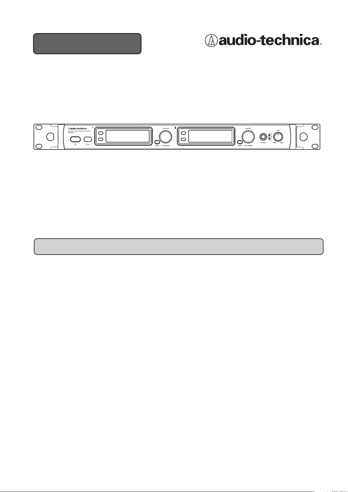
UHF SYNTHESIZED DIVERSITY RECEIVER
ATW-R6200 S
Thank you for purchasing this product.
Before using the product, take time to read this user manual thoroughly to ensure that you will use the product
correctly. Also keep this user manual handy, along with the warranty, so that they are always available for reference.
Features
•
Uses advanced IMD suppression techniques to allow 31 simultaneous channels within a
4 MHz tuning bandwidth
•
High-performance filtering removes external noise from outside of the tuning bandwidth
•
Clear, easy-to-read display
•
Easy transmitter setup via IR sync
•
Headphone output jack for monitoring receiver output
•
Ethernet connection allows monitoring and controlling via a PC
•
Ethernet interface for monitoring and controlling system parameters via a PC
•
Metal full-rack receiver chassis with reinforced mounting ears and rear rack mount
capability
Page 2

Contents
Features ..........................................................................1
Important information ...............................................................3
Notes on use .......................................................................4
Using multiple wireless systems ...................................................... 4
Maintenance .......................................................................4
Part names and functions <front panel> ................................................5
Part names and functions <rear panel> .................................................6
Part names and functions <display> ...................................................7
Minimum hold function ............................................................8
System operation ...................................................................8
Settings ...........................................................................9
Main menu ......................................................................9
Items configurable from the main menu ..............................................9
Setting the operating frequency ....................................................10
Setting the name ................................................................10
Correcting characters ......................................................................11
Setting the squelch level .......................................................... 11
Setting the audio output level ..................................................... 11
Setting the line and mic levels .....................................................12
Setting the system-related functions ................................................12
Setting the key lock .......................................................................12
Setting the lock code ......................................................................13
Setting the antenna power ..................................................................13
Setting transmitters via IR sync ..............................................................14
Screen saver settings .....................................................................14
Resetting factory defaults ..................................................................15
Checking the product information ............................................................15
Setting up the network ...........................................................16
Obtaining an IP address ...................................................................16
Setting the IP address .....................................................................16
Setting the subnet mask ...................................................................17
Displaying the MAC address ................................................................17
Changing the DHCP server setting ...........................................................17
Setting up transmitter via IR sync .....................................................18
Using the key lock function ..........................................................19
Setting up the key lock function ....................................................19
Cancelling the key lock function .................................................... 19
Making connections (basic connections) ...............................................20
Example using an external antenna (sold separately) ....................................21
Achieving stable reception ..........................................................21
Front antenna connections ..........................................................22
Rack mounting receivers ............................................................22
Specifications .....................................................................23
Dimensions .......................................................................23
2
Page 3
Important information
Warning:
•
To prevent fire or shock hazard, do not expose this apparatus to rain or moisture.
Caution:
• Do not expose this apparatus to drips or splashes.
• To avoid electric shock, do not open the cabinet.
• Refer servicing to qualified personnel only.
•
Do not expose this apparatus to excessive heat such as sunshine, fire or the like.
• Do not subject this apparatus to strong impact.
• This apparatus should be located close enough to the AC outlet so
that you can easily grasp the power cord plug at any time.
• In case of emergency, disconnect the power cord plug of this
apparatus quickly.
•
Do not place any objects filled with liquids, such as vases, on this
apparatus.
• To prevent fire, do not place any naked flame sources (such as
lighted candles) on this apparatus.
• Do not install this apparatus in a confined space such as a bookcase
or similar unit.
• Install this apparatus only in places with good ventilation.
• To prevent fire, do not cover the vents of this apparatus with
newspapers, tablecloths, curtains, etc.
• This apparatus with ClassΙconstruction shall be connected to an
AC outlet with a protective grounding connection.
• This apparatus is not disconnected from the mains as long as it is
connected to an AC outlet, even if the unit itself has been turned
off.
• The rating label appears on the bottom of this apparatus.
For customers in the USA
CAUTION
RISK OF ELECTRIC SHOCK
DO NOT OPEN
Caution:
no user-serviceable parts inside. Internal adjustments are for qualified
professionals only. Refer all servicing to qualified service personnel.
To prevent electric shock, do not remove the cover. There are
The lightning flash with arrowhead symbol, within an
equilateral triangle, is intended to alert the user to the
presence of uninsulated “dangerous voltage” within the
product's enclosure that may be of sufficient magnitude to
constitute a risk of shock to persons.
The exclamation point symbol within an equilateral
triangle is intended to alert the user to the presence
of important operating and maintenance (servicing)
instructions in the literature accompanying the product.
Important Safety Instructions
1. Read these instructions.
2. Keep these instructions.
3. Heed all warnings.
4. Follow all instructions.
5. Do not use this apparatus near water.
6. Clean only with dry cloth.
7. Do not block any ventilation openings. Install in accordance
with the manufacturer’s instructions.
8. Do not install near any heat sources such as radiators, heat
registers, stoves, or other apparatus (including amplifiers) that
produce heat.
9. Do not defeat the safety purpose of the polarized or
grounding-type plug. A polarized plug has two blades with one
wider than the other. A grounding type plug has two blades
and a third grounding prong. The wide blade or the third prong
are provided for your safety. If the provided plug does not fit
into your outlet, consult an electrician for replacement of the
obsolete outlet.
10. Protect the power cord from being walked on or pinched
particularly at plugs, convenience receptacles, and the point
where they exit from the apparatus.
11. Only use attachments/accessories specified by the
manufacturer.
12.
Use only with a cart, stand, tripod, bracket or table
specified by the manufacturer, or sold with the
apparatus. When a cart is used, use caution when
moving the cart/apparatus combination to avoid
injury from tip-over.
13. Unplug this apparatus during lightning storms or
when unused for long periods of time.
14. Refer all servicing to qualified service personnel. Servicing is
required when the apparatus has been damaged in any way,
such as power-supply cord or plug is damaged, liquid has been
spilled or objects have fallen into the apparatus, the apparatus
has been exposed to rain or moisture, does not operate normally,
or has been dropped.
FCC Notice
Warning:
This device complies with Part 15 of the FCC Rules. Operation is
subject to the condition that this device does not cause harmful
interference.
Caution:
You are cautioned that any changes or modifications not
expressly approved in this manual could void your authority to
operate this equipment.
Note: This equipment has been tested and found to comply
with the limits for a Class B digital device, pursuant to part
15 of the FCC Rules. These limits are designed to provide
reasonable protection against harmful interference in a
residential installation. This equipment generates, uses and
can radiate radio frequency energy and, if not installed and
used in accordance with the instructions, may cause harmful
interference to radio communications. However, there is
no guarantee that interference will not occur in a particular
installation. If this equipment does cause harmful interference
to radio or television reception, which can be determined by
turning the equipment off and on, the user is encouraged to
try to correct the interference by one or more of the following
measures:
- Reorient or relocate the receiving antenna.
- Increase the separation between the equipment and receiver.
- Connect the equipment into an outlet on a circuit different from
that to which the receiver is connected.
- Consult the dealer or an experienced radio/TV technician for
help.
3
Page 4

Notes on use
• Two transmitters on the same frequency cannot be used simultaneously.
• Please be aware that interference may be generated from the surrounding electromagnetic environment and/or from
using multiple units.
• The wireless system may be affected by electromagnetic noise from automobile spark plugs, light dimmers, computers,
OA devices, or electrical music instruments. Position the components of the system in a place where it is less likely to be
affected.
• Only use this product in combination with devices specified by the manufacturer.
• Insert the plugs of connecting cables securely into their mating connectors.
• Radio waves in the UHF band propagate mainly by line of sight. Configure system so there are no obstructions between
the transmitter and receiver.
• Do not use outside the USA. Use abroad may be punished according to the laws of the relevant country.
• Unplug the product when unused for long periods of time.
• Use 120 V AC power source. Refer to "Specifications" for product ratings.
Using multiple wireless systems
• When using multiple units simultaneously, maintain approximately 1 meter or more between individual transmitters and
approximately 10 meters or more between transmitters and receivers.
•
When using multiple units, power on transmitters one by one, making sure there is no unwanted noise.
Maintenance
• When you unplug the power cable, if the plug is dusty or dirty, wipe it off with a soft, dry cloth.
• Do not use anything like benzene or paint thinner to clean the product.
• When storing the system for an extended period, wrap the device in plastic to protect it from dust.
4
Page 5
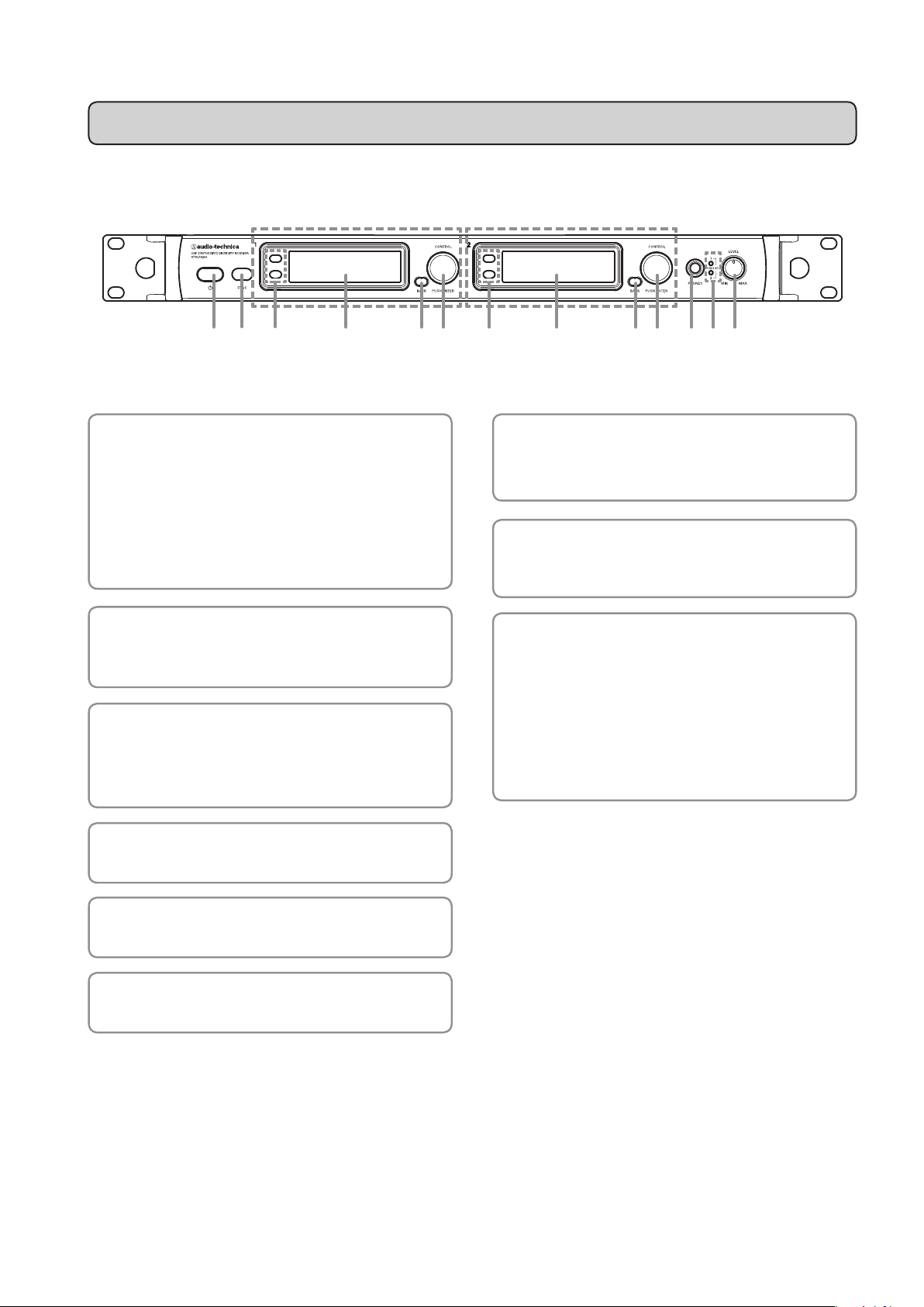
Part names and functions <front panel>
Receiver 1 Receiver 2
(2)
(1) Power switch
Press the switch to turn the power on.
The display lights up when the power is turned on.
*
There will be a delay of up to 5 seconds between
powering on and audio output from the product.
Press the switch again to turn the power off.
(2) IR sync window
Use when syncing transmitter to the product.
*This is shared by receivers 1 and 2.
(3) Function buttons
Upper button (FN1): Switches the level meter display.
Lower button (FN2): Minimum hold (only in level meter
display mode).
(9)(8)(7)(6)(5)(6)(5) (4)(3)(4)(3)(1)
(7) Headphone monitor(6.3 mm)output jack
This is the headphone output jack used for monitoring.
It allows you to monitor receivers 1 and 2.
(8) Headphone channel indicator
Displays which receiver is being monitored, receiver 1
or 2.
(9) Headphone volume
Use when adjusting the volume of the headphones for
monitoring.
Press and release the knob to switch between
receivers 1 and 2.
*Does not affect receiver audio output level.
(4) Display
Displays the product state and setting menus.
(5) BACK button
Takes the display back one screen when pressed.
(6) Control dial
Turn to scroll through settings and press to set them.
5
Page 6
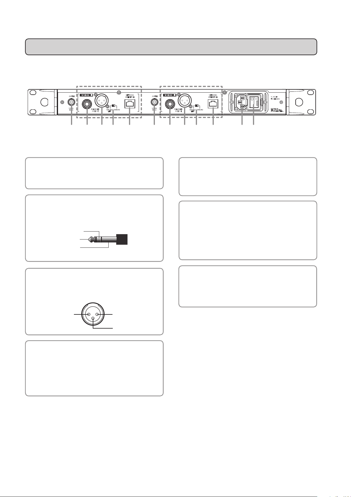
Part names and functions <rear panel>
3. COLD
1. GND
Receiver 2
GROUND
NETWORK
INTERFACE
12V
60mA
2
RECEIVER
ANT B ANT A
12V
60mA
BALANCED
OUTPUT
GROUND
LIFT
(2) (2)
(1) Antenna input jack
Each of the antenna jacks can supply 12 V DC for use
with powered antennas or accessories (sold separately).
(2) Balanced output jack
(6.3 mm (1/4") standard stereo jack)
COLD
HOT
GND
Receiver 1
1
RECEIVER
BALANCED
OUTPUT
(5) Network interface
Connecting to a PC via Ethernet cable allows you to
monitor and control the system from the PC. For
details, contact your local Audio-Technica dealer.
(6) AC IN terminal
Use the IEC-type connector for 120 V AC 60 Hz power
input.
*This product is only for use in the USA. It may not be used
GROUND
LIFT
abroad.
GROUND
NETWORK
INTERFACE
AC IN
T2 AH 250V
max. 250V~
:
WARNING
THIS APPARATUS
MUST BE EARTHED.
(7)(6)(5)(5) (4)(3)(4)(3)(1) (1)
(3) Balanced output jack
(XLR 3-pin male)
2. HOT
(4) Ground lift switch
This switch isolates the GND pin of the balanced
output from the ground.
Normally use in the GROUND position, but if a hum
develops due to a ground loop, switch to the "GROUND
LIFT" side.
(7) Main power switch
Press the main power switch to turn the power on.
Turn the main power switch on before turning the front
panel power switch on.
6
Page 7
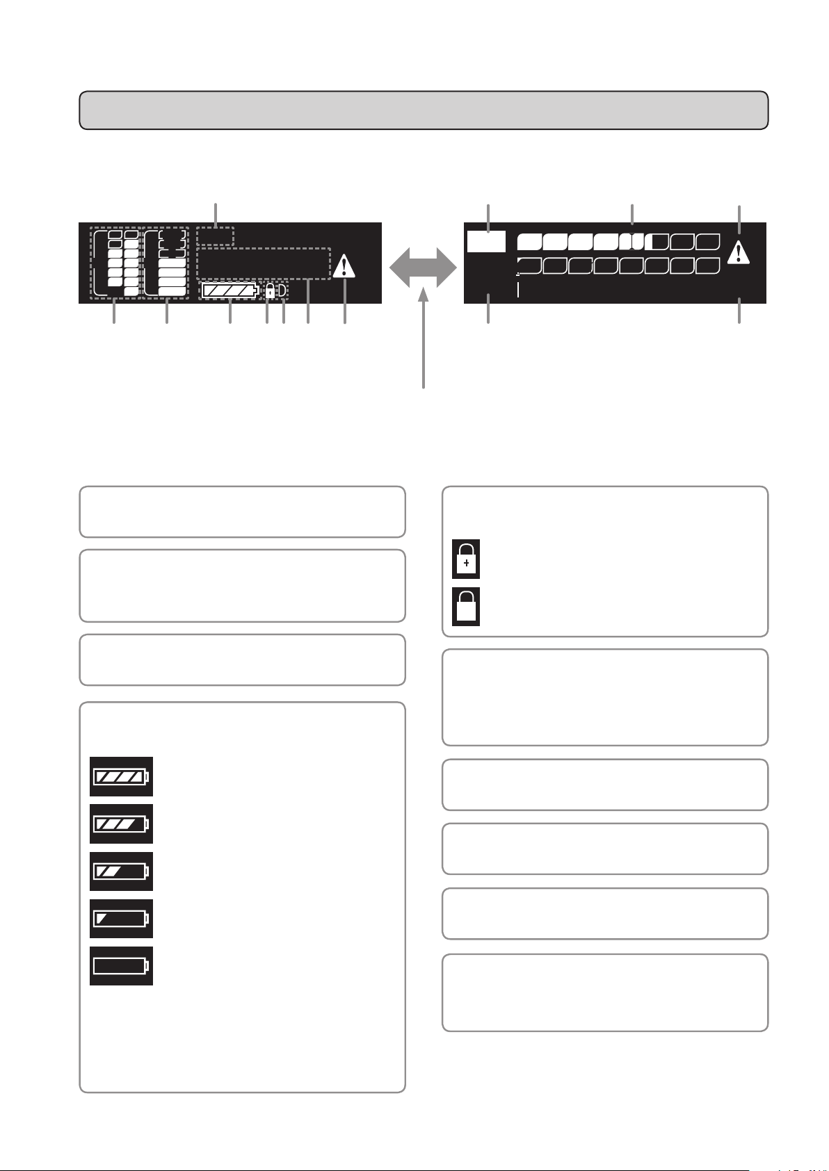
Part names and functions <display>
Main Screen 1 Main Screen 2
(1)
PEAK
Vocal
+10
RF AF
a b
Each time you press the Function button (FN1) on the main screen, it switches between screens.
*When on any screen other than the main screen, pressing the Function button (FN1) switches it back to main screen 1.
0
–10
–20
946.125
–30
–40
(3)(2)
(5)(4)
MHz
(6) (7) (3)
(8)
FN1
(1) NAME
Displays the specified name.
(2) RF level indicator
Displays the reception states of antennas A & B,
respectively.
(2)
RF –A
RF –B
Audio PEAK
(5) Key lock and network remote
–40 –30 –20 –10 0+10
: Key lock is ON
: Network remote state
(10)
(8)
(9)
(3) AF level indicator
Displays the received audio signal level.
(4) Battery level
Shows the battery level of the transmitter.
: 75% or more battery power remaining.
: 50 to 75% battery power remaining.
: 25 to 50% battery power remaining.
: 25% or less battery power remaining.
: Charge/replace the batteries.
*Use as a general guide for determining how much
battery power has been consumed.
*If there is no remaining battery power, replace the
transmitter’s batteries. If rechargeable batteries are
being used, recharge them.
(6) DHCP server operation indicator
Displayed when the DHCP server operation setting is
ON.
(7) Frequency
Displays the set frequency.
(8) Mute indicator
An exclamation point icon is displayed when muted.
(9) Peak indicator
Displayed if the AF level exceeds +18 dBV.
(10)
Marker (when the minimum hold
function is on)
The RF level is held at a minimum value.
7
Page 8
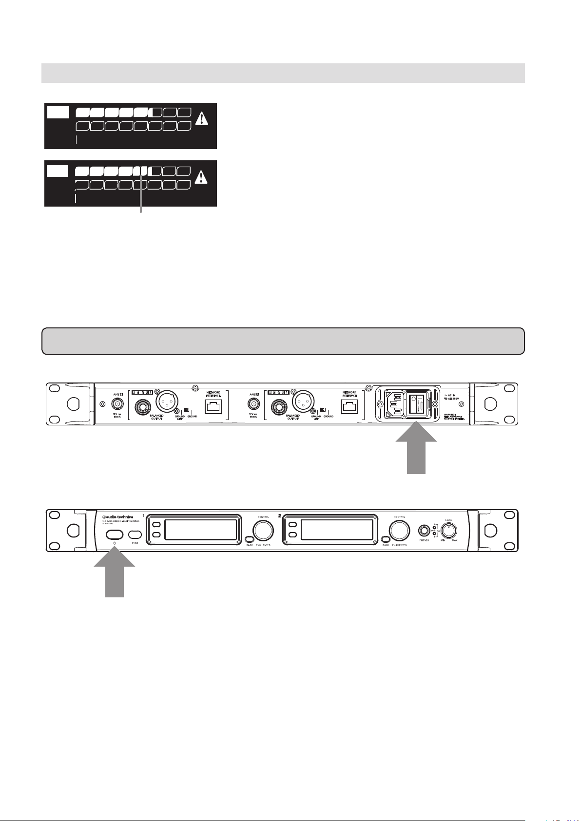
Minimum hold function
Audio PEAK
RF –A
RF –B
–40 –30 –20 –10 0+10
Audio PEAK
RF –A
RF –B
–40 –30 –20 –10 0+10
Marker
(1) When on the main screen, pressing the function button
(FN1) switches the display to main screen 2.
(2) If you press and hold the function button (FN2), the
minimum hold function turns on and its marker is
displayed.
◦ The marker indicates the lowest-level RF signal
received from the transmitter.
◦ The marker does not move even if the input RF level is
higher than the marker position.
◦ If the RF level input is lower than the marker position,
the marker moves in tandem with the RF level.
◦ To reset the marker position, press the Function button
(FN2).
System operation
Rear Panel
Front Panel
(2) Power switch
(1) Turn the main power switch on the rear panel [ON].
(2) Turn the power switch on the front panel [ON].
◦ The display lights and the frequency is displayed.
(3) Set the operating frequency (see p. 10).
(4) Turn the transmitter’s power on and sync with receiver (see p. 18).
◦ The RF level indicator lights up.
(5) Check the RF level indicator.
◦ Check that antenna A or B lights up.
(6) Speak into the mic.
◦ Make sure the AF level indicator lights up.
(1) Main power switch
8
Page 9

Settings
Main menu
The various settings of this product can be made from the main menu.
PEAK
+10
RF AF
a b
RF AF
a b
0
–10
–20
946.125
–30
–40
PEAK
+10
–10
–20
–30
–40
0
946
Frequency
Squelch
Audio Settings
MHz
Items configurable from the main menu
(1) On the main screen, press or turn the control dial to
display the main menu.
(2) Turn the control dial to select the item you wish to set.
(3) Pressing the control dial opens the settings menu of the
selected item.
◦ Press the BACK button to go back one screen.
◦ To cancel part way through making a setting, press the
BACK button.
◦ While in the setting mode, the display will return to the
main screen if 30 seconds pass without a button or the
control dial being used.
Frequency Management Sets the operating frequency and corresponding name.
Squelch Sets the squelch level.
Audio Settings Sets the audio output level, and the line/mic levels.
System Settings Configures the following functions:
◦ Key lock
◦ Antenna power
◦ IR sync
◦ Screen saver
◦ Factory-defined defaults
TX SYNC Syncs transmitter with the product.
Network Configures network settings.
9
Page 10

Setting the operating frequency
PEAK
+10
RF AF
a b
Frequency Management
Frequency Management
Frequency Management
0
–10
–20
–30
–40
946 . 125
.
125946
.
946 125
946
MHz
MHz
MHz
Setting the name
Frequency
Squelch
Audio Settings
FREQ
NAME
FREQ
NAME
FREQ
NAME
(1) From the main menu, turn the control dial, select
[Frequency] and then press the control dial.
(2) Select [FREQ] and press the control dial.
(3) Turn the control dial and set the first 3 digits. When
finished setting them, press the control dial.
(4) Turn the control dial and set the last 3 digits. When
finished setting them, press the control dial.
◦ The setting is complete.
The following characters can be entered:
◦ Alphabetical characters (upper and lower case) ◦ Numbers
◦ Symbols (+, -, period) ◦ Spaces
PEAK
+10
RF AF
a b
Frequency Management
Frequency Management
–10
–20
–30
–40
0
946
V
Frequency
Squelch
Audio Settings
FREQ
NAME
FREQ
NAME
(1) From the main menu, turn the control dial, select
[Frequency] and then press the control dial.
(2) Select [NAME] and press the control dial.
(3) Turn the control dial to display the character you wish to
set and then press the control dial.
◦ The character is input and the cursor moves to the
right.
Frequency Management
Vocal2
FREQ
NAME
(4) Enter all the desired characters in the same way as in
step (3) and then press the control dial.
◦ The NAME is saved.
10
NOTE: A total of 10 characters must be entered. If less
than 10 characters are desired, select SPACE and
press the control dial until the cursor moves to the
10th character position.
Page 11

Correcting characters
There are two ways to correct text that has been entered.
● If you wish to delete text
Turn the control dial and select [BS]. When you press the control dial, the cursor moves one space to the left, backspacing
over the last character entered.
● To move to the character you wish to correct
Press the BACK button and the cursor moves back one place. Move the cursor back to the character you wish to change.
Turn the control dial to display the character you wish to set and then press the control dial.
Setting the squelch level
PEAK
RF AF
a b
Squelch
OFF
Squelch
OFF
+10
0
–10
–20
946
–30
–40
20 dBuV
50 dBuV
Frequency
Squelch
Audio Settings
Frequency
Squelch
50
Audio Settings
Frequency
Squelch
50
Audio Settings
Setting the audio output level
PEAK
RF AF
a b
+10
–10
–20
–30
–40
0
946
Frequency
Squelch
Audio Settings
(1) From the main menu, turn the control dial, select
[Squelch] and then press the control dial.
(2) Turn the control dial and select the value you wish to set.
◦
The meter indicates the RF level.
◦ You can set it from OFF up to the maximum 50dBμV.
◦ The default setting is 20dBμV.
(3) Press the control dial.
◦ The setting is complete.
(1) From the main menu, turn the control dial, select
[Audio Settings] and then press the control dial.
Audio Settings
Audio Settings
–20 dB
0 dB
GAIN
LINE/MIC
0–20
GAIN
LINE/MIC
0–20
(2) Select [GAIN] and press the control dial.
(3) Turn the control dial and set the audio output level.
◦ The level changes 2dB +/- each time you turn the
control dial.
◦ It can be set from -20 to 0dB.
(4) Press the control dial.
◦ The setting is complete.
11
Page 12

Setting the line and mic levels
Key Lock
Lock Code
ANT PWR
System Settings
OFFON
PEAK
RF AF
a b
Audio Settings
LINE MIC
Audio Settings
LINE MICMICLINE
+10
–10
–20
–30
–40
0
946
Frequency
Squelch
Audio Settings
GAIN
LINE/MIC
GAIN
LINE/MIC
Setting the system-related functions
(1) From the main menu, turn the control dial, select
[Audio Settings] and then press the control dial.
(2) Select [LINE/MIC] and press the control dial.
(3) Turn the control dial and select either [LINE] or [MIC].
(4) Press the control dial.
◦ The setting is complete.
Setting the key lock
Set this function to prevent the product settings from being changed.
*The default setting is [OFF].
PEAK
+10
RF AF
a b
System Settings
–10
–20
–30
–40
0
946
OFFON
Squelch
Audio Settings
System Settings
Key Lock
Lock Code
ANT PWR
(1) From the main menu, turn the control dial, select
[System Settings] and then press the control dial.
(2) Select [Key Lock] and press the control dial.
(3) Turn the control dial, select [ON] or [OFF] and then press
the control dial.
◦ The setting is complete.
12
Page 13

Setting the lock code
The lock code is a 4-digit number used with the key lock. (Can be set from "0000" to "9999".)
When the key lock function is activated, the lock code is required to access the menu from the main screen.
*The default setting is "0000".
PEAK
+10
RF AF
a b
System Settings
System Settings
–10
–20
–30
–40
0
System Settings
0
946
9
Squelch
Audio Settings
System Settings
Key Lock
Lock Code
ANT PWR
Key Lock
Lock Code
ANT PWR
Key Lock
Lock Code
ANT PWR
Setting the antenna power
This turns power on/off to the antenna input terminals.
*The default setting is [OFF].
*This can only be set from receiver 1.
*If set to [ON], power is supplied to both antennas A and B.
(1) From the main menu, turn the control dial, select
[System Settings] and then press the control dial.
(2) Select [Lock Code] and press the control dial.
(3) Turn the dial to select a number and then press the
control dial.
(4) Repeat the operation until all 4 numbers are entered and
then press the control dial.
◦ The setting is complete.
PEAK
+10
RF AF
a b
System Settings
System Settings
–10
–20
–30
–40
0
946
OFFON
OFFON
Squelch
Audio Settings
System Settings
Key Lock
Lock Code
ANT PWR
Key Lock
Lock Code
ANT PWR
(1) From the main menu, turn the control dial, select
[System Settings] and then press the control dial.
(2) Select [ANT PWR] and press the control dial.
(3) Turn the control dial, select [ON] or [OFF] and then press
the control dial.
◦ The setting is complete.
13
Page 14

Setting transmitters via IR sync
This function allows you to make transmitter settings on the product and then automatically configure the transmitter via
IR sync.
PEAK
+10
RF AF
a b
System Settings
RF PWR,HIGH MIC GAIN, 10
KEY LOCK,OFF
BATT ,Alkaline
System Settings
RF PWR,HIGH MIC GAIN, 10
KEY LOCK,OFF
BATT ,Alkaline
System Settings
RF PWR,HIGH MIC GAIN, 10
KEY LOCK,OFF
BATT ,Alkaline
System Settings
RF PWR,HIGH MIC GAIN, 10
KEY LOCK,OFF
BATT ,Alkaline
–10
–20
–30
–40
0
946
Squelch
Audio Settings
System Settings
Lock Code
ANT PWR
TX SET
Lock Code
ANT PWR
TX SET
Lock Code
ANT PWR
TX SET
Lock Code
ANT PWR
TX SET
(1) From the main menu, turn the control dial, select
[System Settings] and then press the control dial.
(2) Select [TX SET] and press the control dial.
(3) To set the [RF PWR], turn the control dial, select [HIGH],
[MID] or [LOW] and then press the control dial.
(4) To set the [MIC GAIN], turn the control dial, select the
gain and then press the control dial.
◦ The gain can be set in steps of 2dB.
◦ The maximum setting is 20dB.
(5) To set the [KEY LOCK] (transmitter key lock), turn the
control dial, select [ON] or [OFF] and then press the
control dial.
System Settings
RF PWR,HIGH MIC GAIN, 10
KEY LOCK,OFF
BATT ,Alkaline
Lock Code
ANT PWR
TX SET
(6) To set the [BATT] (type of battery used in the transmitter),
turn the control dial, select [Alkaline] or [Ni-MH] and then
press the control dial.
Alkaline Select when using alkaline batteries.
Ni-MH Select when using nickel–metal hydride batteries.
◦ The setting is complete.
NOTE: For how to sync a transmitter with the receiver,
Screen saver settings
This sets the length of time before the display turns off from inactivity.
*The default setting is set to "OFF" and the screen does not turn off.
PEAK
+10
RF AF
a b
System Settings
–10
–20
–30
–40
0
946
LCD auto off time
minute
1
Squelch
Audio Settings
System Settings
ANT PWR
TX SET
Screen Saver
(1) From the main menu, turn the control dial, select
[System Settings] and then press the control dial.
(2) Select [Screen Saver] and press the control dial.
refer to "Setting up transmitter via IR sync" (p.18).
System Settings
LCD auto off time
minute
5
14
ANT PWR
TX SET
Screen Saver
(3) Turn the control dial, select the desired amount of time
and then press the control dial.
◦ The setting is complete.
◦ If you select [OFF], the display will not turn off.
◦ The time can be set from 1 to 99 minutes.
Page 15

Resetting factory defaults
This returns the settings to their factory defaults.
PEAK
+10
RF AF
a b
System Settings
–10
–20
–30
–40
Reset ?
System Settings
Reset ?
YES NO
0
946
Squelch
Audio Settings
System Settings
TX SET
Screen Saver
RESET
TX SET
Screen Saver
RESET
Checking the product information
This function displays product information.
PEAK
RF AF
a b
+10
–10
–20
–30
–40
0
946
Squelch
Audio Settings
System Settings
(1) From the main menu, turn the control dial, select
[System Settings] and then press the control dial.
(2) Select [RESET] and press the control dial.
(3) Select [YES] and press the control dial.
◦ Reset starts. After the reset is complete, the product
powers off and on.
(1) From the main menu, turn the control dial, select
[System Settings] and then press the control dial.
System Settings
Audio-Technica Co, Ltd
ATW–R6200 SN00000000
1. 0. 000 BAND
09:47:32 Aug 12 2015
Screen Saver
RESET
VERSION
● Information you can check:
System Settings
(1)
(2)
(3)
(4)
(1) Company name
(2) Product model and serial number
(3) Firmware version and frequency band name
(4) Date/time firmware created
Audio-Technica Co, Ltd
ATW–R6200 SN00000000
1. 0. 000 BAND
09:47:32 Aug 12 2015
(2) Select [VERSION].
◦ Product information is displayed.
Screen Saver
RESET
VERSION
15
Page 16

Setting up the network
Connecting to a PC via Ethernet cable allows you to monitor and control the system from the PC.
The settings made here are not reflected until the product is restarted. After you change settings, a screen opens to inform
you that you have to restart.
Obtaining an IP address
This sets how the IP address is selected.
PEAK
+10
RF AF
a b
Network
–10
–20
–30
–40
0
AutoIP STATIC
Network
AutoIP STATIC
946
System Settings
TX SYNC
Network
IP Select
IP Address
Subnet Mask
IP Select
IP Address
Subnet Mask
Setting the IP address
This configures the IP address.
*This can only be configured when [IP Select] is set to [STATIC].
(1) From the main menu, turn the control dial, select
[Network] and then press the control dial.
(2) Select [IP Select] and press the control dial.
(3) Select the desired setting and press the control dial.
AutoIP This sets the system to automatically
assign an IP address.
STAT I C This sets the system to use a fixed IP
address.
◦ The setting is complete. Restart the product after
completing all the network settings.
PEAK
+10
RF AF
a b
Network
–10
–20
–30
–40
0
0 , 0 , 0 , 0
Network
192 , 0 , 0 , 0
Network
192 , 168 , 1 , 1
16
946
System Settings
TX SYNC
Network
IP Select
IP Address
Subnet Mask
IP Select
IP Address
Subnet Mask
IP Select
IP Address
Subnet Mask
(1) From the main menu, turn the control dial, select
[Network] and then press the control dial.
(2) Select [IP Address] and press the control dial.
(3) Turn the dial and select the number you wish to set and
press the control dial.
(4) Repeat the operation until all the numbers are entered
and then press the control dial.
◦ The setting is complete. Restart the product after
completing all the network settings.
Page 17

Setting the subnet mask
This configures the subnet mask.
*This can only be configured when [IP Select] is set to [STATIC].
PEAK
+10
RF AF
a b
Network
–10
–20
–30
–40
0
946
255, 255, 255, 0
Network
255, 255, 255, 0
Network
255, 255, 255, 0
System Settings
TX SYNC
Network
IP Select
IP Address
Subnet Mask
IP Select
IP Address
Subnet Mask
IP Select
IP Address
Subnet Mask
Displaying the MAC address
This allows you to check the MAC address.
(1) From the main menu, turn the control dial, select
[Network] and then press the control dial.
(2) Select [Subnet Mask] and press the control dial.
(3) Turn the dial and select the number you wish to set and
press the control dial.
(4) Repeat the operation until all the numbers are entered
and then press the control dial.
◦ The setting is complete. Restart the product after
completing all network settings.
PEAK
+10
RF AF
a b
Network
–10
–20
–30
–40
0
946
00:00:00:00:00:00
System Settings
TX SYNC
Network
IP Address
Subnet Mask
MAC Address
(1) From the main menu, turn the control dial, select
(2) Select [MAC Address].
Changing the DHCP server setting
This sets whether or not to use a DHCP server.
*If you wish to use a DHCP server, you must set [IP Select] to [STATIC].
(1) From the Main menu, turn the control dial, select
(2) Select [DHCP Server] and press the control dial.
RF AF
a b
Network
PEAK
+10
0
–10
–20
–30
–40
OFFON
946
System Settings
TX SYNC
Network
Subnet Mask
MAC Address
DHCP Server
[Network] and then press the control dial.
◦ The MAC address is displayed.
[Network] and then press the control dial.
Network
(3) Turn the dial and select either [ON] or [OFF] and press the
Subnet Mask
OFFON
MAC Address
DHCP Server
control dial.
◦ The setting is complete. Restart the product after
completing all network settings.
17
Page 18

Setting up transmitter via IR sync
This function allows you to send the settings configured on the product to the transmitter via IR sync.
*First refer to the section "Setting transmitters via IR sync" (p. 14) and then make the settings.
PEAK
+10
RF AF
a b
TX Sync
Ir bus arbitration..OK
Connect..OK
Send and Wait..
–10
–20
–30
–40
0
946
Audio Settings
System Settings
TX SYNC
Audio Settings
System Settings
TX SYNC
(1) From the main menu, turn the control dial, select
[TX SYNC] and then press the control dial.
(2) A standby screen is displayed.
◦ Press the BACK button to return to the main menu.
◦ If 60 seconds pass without a button/dial being used,
the display will return to the main menu.
(3) While in standby mode, position the IR sync windows of
the product and transmitter so they face each other.
(4) Press the SYNC button on the transmitter.
◦ Wait several seconds until communication is
established.
TX Sync
Ir bus arbitration..OK
Connect..OK
Send and Wait..OK
Close and End.
Audio Settings
System Settings
TX SYNC
(5) When the sync is complete, the “completed” screen is
displayed.
◦ The settings made on the product are automatically
sent to the transmitter.
◦ After sync is complete, the display returns
automatically to the main screen.
◦ If an error occurs in the syncing process, an error
screen opens and then the display returns to the main
menu. Check the alignment of the IR sync windows of
the receiver and transmitter and then sync again.
◦ To cancel the syncing process, press the BACK button.
Display returns to the main menu.
18
Page 19

Key Lock
Lock Code
ANT PWR
System Settings
OFFON
710.125
a b
RF AF
PEAK
0
–10
–20
–30
–40
–50
NAMEAREA12
MHz
PIN INPUT
710.125
a b
RF AF
PEAK
0
–10
–20
–30
–40
–50
NAMEAREA12
MHz
0
PIN INPUT
710.125
a b
RF AF
PEAK
0
–10
–20
–30
–40
–50
NAMEAREA12
MHz
9
PIN INPUT
Using the key lock function
The key lock function prevents entry to the main menu to avoid any unwanted changes to the system's settings.
When the key lock function is set to [ON], the main screen is displayed, but a lock code is required in order to access the
main menu.
Setting up the key lock function
System Settings
Key Lock
Lock Code
ANT PWR
Cancelling the key lock function
(1). Set up a lock code.
◦ For details, refer to "Setting the lock code" on p. 13.
◦ Do not forget the 4-digit code you set up.
(2) Set the key lock function to [ON].
◦ For details, refer to "Setting the key lock" section on
p. 12.
(3) The key lock function is enabled once you press the
BACK button and return to the main screen.
(1) When the key lock is enabled, the PIN INPUT screen is
displayed when you press or turn the control dial on the
main screen.
(2) To release the lock, enter the 4-digit lock code. Turn the
control dial to select a number and then press the control
dial. Once you enter a number, the cursor moves to the
right. Repeat the steps to enter the 4-digit lock code.
(3) After the entire 4-digit code is entered, press the control
button. If the correct lock code was entered, the main
menu will display.
(4) The key lock function can be released by turning the key
lock setting [OFF].
19
Page 20

Making connections (basic connections)
This example is of connections made when using one ATW-R6200 S.
When connecting more than one ATW-R6200 S via a distributor (sold separately), refer to the distributor's
user manual.
Connection example
ATW-A
Antenna Antenna
49
Mixer IN
ATW-A
Mixer IN
49
ATW-R
6200 S
PC PC
NOTE: The example connection shown above uses the supplied antennas. When using the product in a large
space or on a stage, connect it to UHF wideband LPDA antennas ATW-A49 (sold separately), as shown
by the dotted lines.
20
Page 21

Example using an external antenna (sold separately)
Caution on antenna location
The distance between antennas A and B should be at least 30 cm and less than 30 m.
Otherwise diversity reception can be lost.
When using 1 set (ATW-A49)
A
B
Achieving stable reception
Low RF signal may result if there are obstructions between receiver antennas and transmitter(s).
In such a case, reposition the antennas to get better reception.
21
Page 22

Front antenna connections
◦ To connect the antennas to the front of the product, attach all parts as shown below.
Rubber washer
Shake proof washer
Rack mounting receivers
◦ Screws for rack mounting the product are not included.
◦
Consider ventilation when rack mounting to avoid heat building up in the rack.
22
Page 23

Specifications
Receiving system
Operating frequency
Simultaneous channels
RF sensitivity
Total harmonic distortion
SN ratio
Audio output level
Antenna input jack
Audio output terminal
Headphone OUTPUT jack
Power
Operating temperature
range
Power consumption
External dimensions
excluding protrusions
(
Weight
)
True diversity
:
946.125 to 949.875 MHz
:
Total of 31 channels (125kHz intervals)
:
20 dB μV (at 60dB S/N ratio)
:
<1% (63 dB μ V input, 1 kHz, frequency deviation ±10 kHz)
:
110 dB or more
:
XLR balanced ≥+18 dBV (LINE), ≥+4 dBV (MIC) (frequency deviation ±15 kHz)
:
:Φ6.3 balanced ≥+18 dBV (LINE), ≥+4 dBV (MIC) (frequency deviation ±15 kHz)
BNC type (50 ohm) 12 V DC OUT (max 60 mA x 2)
:
XLR 3-pin male (balanced)
:
6.3 mm (1/4")
6.3 mm (1/4")
:
120 V AC 60 Hz
:
5℃ to 45 ℃ (41°F to 113 °F)
:
25 W
:
482 mm (18.97") × 43 mm (1.69") × 361 mm (14.21") (W × H × D)
:
4.7 kg (10.4 lbs)
:
standard stereo jack (balanced)
standard stereo jack; max power output: 100 mW + 100 mW into 32 ohms
● Accessories 1/2λ whip antenna x 2, Power cable, Legs x 4 (4 mounting screws), Front mount antenna cables
and connectors
● This product is for use in the USA only.
● Specifications are subject to change without prior notice.
Dimensions
400
482
(Unit: mm)
32.8 361
43
23
Page 24

Audio-Technica Corporation
©2017 Audio-Technica Corporation
232305390-01-02
ver.1 2016.03.31
ver.2 2017.02.01
 Loading...