

Page 1
UHF ANTENNA DISTRIBUTION SYSTEM
ATW-DA410
UHF ANTENNA DISTRIBUTION SYSTEM
E
N
F
R
E
S
P
T
User Manual
SYSTÈME DE DISTRIBUTION À ANTENNE UHF
Manuel de l’utilisateur
SISTEMA DE DISTRIBUCIÓN DE ANTENAS UHF
Manual del usuario
SISTEMA DE DISTRIBUIÇÃO DE ANTENAS UHF
Manual do Usuário
Page 2
Thank you for purchasing this product.
Before using the product, take time to read this user manual thoroughly to ensure that you will use the product correctly.
Also keep this user manual handy, along with the warranty, so that they are always available for reference.
Important information
Warning:
•
To prevent fire or shock hazard, do not expose this apparatus to rain or moisture.
Caution:
• Do not expose this apparatus to drips or splashes.
• To avoid electric shock, do not open the cabinet.
• Refer servicing to qualified personnel only.
•
Do not expose this apparatus to excessive heat such as sunshine, fire or the like.
• Do not subject this apparatus to strong impact.
• This apparatus should be located close enough to the AC outlet so
that you can easily grasp the power cord plug at any time.
• In case of emergency, disconnect the power cord plug of this
apparatus quickly.
•
Do not place any objects filled with liquids, such as vases, on this
apparatus.
• To prevent fire, do not place any naked flame sources (such as
lighted candles) on this apparatus.
• Do not install this apparatus in a confined space such as a bookcase
or similar unit.
• Install this apparatus only in places with good ventilation.
• To prevent fire, do not cover the vents of this apparatus with
newspapers, tablecloths, curtains, etc.
• This apparatus with ClassΙconstruction shall be connected to an
AC outlet with a protective grounding connection.
• This apparatus is not disconnected from the mains as long as it is
connected to an AC outlet, even if the unit itself has been turned
off.
• The rating label appears on the bottom of this apparatus.
For customers in the USA
UL/CSA notice
CAUTION
RISK OF ELECTRIC SHOCK
DO NOT OPEN
Caution:
no user-serviceable parts inside. Internal adjustments are for qualified
professionals only. Refer all servicing to qualified service personnel.
To prevent electric shock, do not remove the cover. There are
The lightning flash with arrowhead symbol, within an
equilateral triangle, is intended to alert the user to the
presence of uninsulated “dangerous voltage” within the
product's enclosure that may be of sufficient magnitude to
constitute a risk of shock to persons.
The exclamation point symbol within an equilateral
triangle is intended to alert the user to the presence
of important operating and maintenance (servicing)
instructions in the literature accompanying the product.
Important Safety Instructions
1. Read these instructions.
2. Keep these instructions.
3. Heed all warnings.
4. Follow all instructions.
5. Do not use this apparatus near water.
6. Clean only with dry cloth.
7. Do not block any ventilation openings. Install in accordance
with the manufacturer’s instructions.
8. Do not install near any heat sources such as radiators, heat
registers, stoves, or other apparatus (including amplifiers) that
produce heat.
9. Do not defeat the safety purpose of the polarized or
grounding-type plug. A polarized plug has two blades with one
wider than the other. A grounding type plug has two blades
and a third grounding prong. The wide blade or the third prong
are provided for your safety. If the provided plug does not fit
into your outlet, consult an electrician for replacement of the
obsolete outlet.
10. Protect the power cord from being walked on or pinched
particularly at plugs, convenience receptacles, and the point
where they exit from the apparatus.
11. Only use attachments/accessories specified by the
manufacturer.
12.
Use only with a cart, stand, tripod, bracket or table
specified by the manufacturer, or sold with the
apparatus. When a cart is used, use caution when
moving the cart/apparatus combination to avoid
injury from tip-over.
13. Unplug this apparatus during lightning storms or
when unused for long periods of time.
14. Refer all servicing to qualified service personnel. Servicing is
required when the apparatus has been damaged in any way,
such as power-supply cord or plug is damaged, liquid has been
spilled or objects have fallen into the apparatus, the apparatus
has been exposed to rain or moisture, does not operate normally,
or has been dropped.
FCC Notice
Warning:
This device complies with Part 15 of the FCC Rules. Operation
is subject to the following two conditions: (1) This device may
not cause harmful interference, and (2) this device must accept
any interference received, including interference that may cause
undesired operation.
Caution:
You are cautioned that any changes or modifications not
expressly approved in this manual could void your authority to
operate this equipment.
Note: This equipment has been tested and found to comply
with the limits for a Class B digital device, pursuant to part
15 of the FCC Rules. These limits are designed to provide
reasonable protection against harmful interference in a
residential installation. This equipment generates, uses and
can radiate radio frequency energy and, if not installed and
used in accordance with the instructions, may cause harmful
interference to radio communications. However, there is
no guarantee that interference will not occur in a particular
installation. If this equipment does cause harmful interference
to radio or television reception, which can be determined by
turning the equipment off and on, the user is encouraged to
try to correct the interference by one or more of the following
measures:
- Reorient or relocate the receiving antenna.
- Increase the separation between the equipment and receiver.
- Connect the equipment into an outlet on a circuit different from
that to which the receiver is connected.
- Consult the dealer or an experienced radio/TV technician for
help.
For customers in Canada
IC statement
CAN ICES-3 (B)/NMB-3(B)
1
Page 3
Maintenance
max. 250V~
(2)
(8)(7)(6)(5)(4)(3)
(1)
• When you unplug the power cable, if the plug is dusty or dirty, wipe it off with a soft, dry cloth.
• Do not use anything like benzene or paint thinner to clean the product.
• When storing the product for an extended period, wrap the product in plastic to protect it from dust.
Notes on use
• The wireless system may be affected by electromagnetic noise from automobile spark plugs, light dimmers, computers, OA
devices, or electric musical instruments. Position the components of the system in a place where they are less likely to be affected.
• Only use this product in combination with devices specified by the manufacturer.
• Do not use outside the USA and Canada. Use abroad may be punished according to the laws of the relevant country.
• Use 120 V AC 60 Hz power source. Refer to "Specifications" for product ratings.
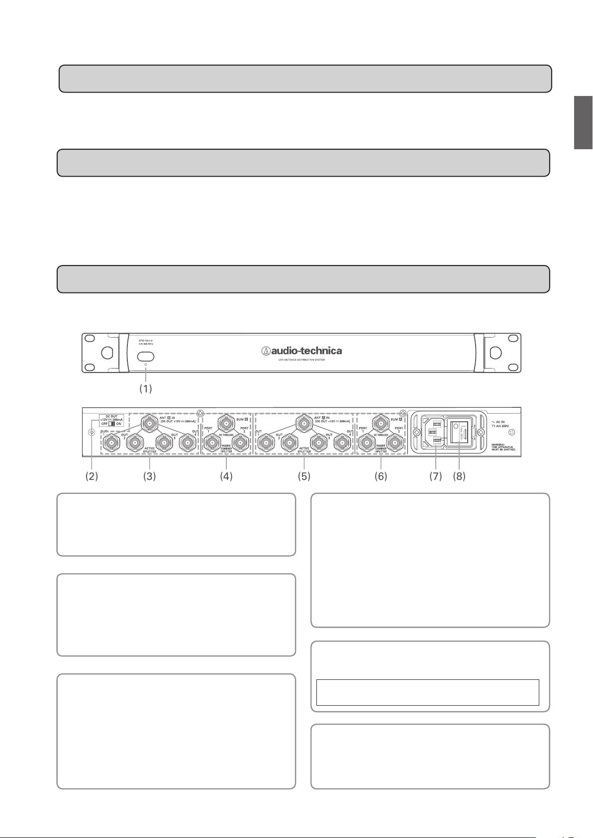
Part names and functions
Front panel
E
N
(1) Power switch
Press the switch to turn the power on.
Press the switch again to turn the power off.
The power switch lights up when the power is turned on.
(2) Antenna power switch
(off when shipped from factory)
By turning the switch on, you supply 12 V DC to ANT A IN or
ANT B IN (antenna input jacks for both channels A and B).
* Power cannot be independently supplied to ANT A IN or ANT B IN.
(3)(5) 1:4 Active splitter section
ANT A IN, ANT B IN:
These are the antenna input jacks for channels A and B. By
turning on the power switch for the antenna, you supply 12
V DC.
OUT 1 to 4:
These are four distribution output jacks for channels A and
B.
Rear panel
(4)(6) 1:2 Passive splitter section/2:1
Passive combiner section
These are distribution and combination sections for
channels A and B.
When input to the SUM jack, signals are distributed to and
output from PORT 1 and 2 jacks.
When input to PORT 1 and 2 jacks, signals are combined
and output from the SUM jack.
* The SUM jack and PORT 1 and 2 jacks support DC through currents.
(7) AC IN terminal
Use the IEC-type connector for 120 V AC 60 Hz power input.
• This product is only for use in the USA and Canada. It may not
be used abroad.
(8) Main power switch
Press the main power switch to turn the power on.
Turn the main power switch on before turning the front
panel power switch on.
2
Page 4
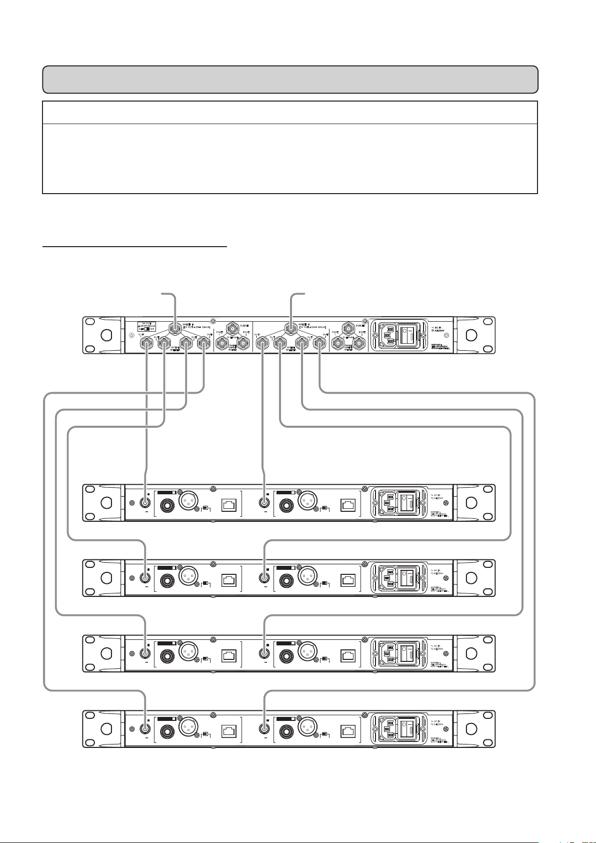
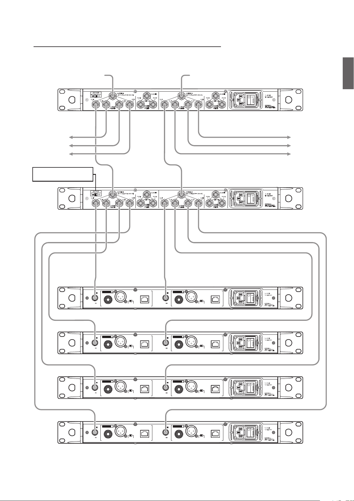
Connection methods (when connected to ATW-R6200 S)
Precautions when connecting
• Make sure to turn off the antenna power supply setting on the receiving device to which you are connecting.
For setup methods, refer to the user manual of the receiver.
• Before connecting an external antenna, be absolutely sure to turn off the antenna power switch.
When supplying power to an external antenna, first connect the antenna and then turn on the antenna power switch.
When distributing four antenna signals
External antenna External antenna
ATW-DA410
DC OUT
+12V 200mA
OFF ON
OUT
1
B A
ANT IN
[
]
+12V 200mA
DC OUT
OUT
2
ACTIVE
SPLITTER
PORT
OUT
4
OUT
3
B A
SUM
PORT
DC THROUGH
PASSIVE
COMBINER
/SPLITTER
OUT
2
1
1
ANT IN
[
]
+12V 200mA
DC OUT
OUT
OUT
2
ACTIVE
SPLITTER
4
OUT
3
SUM
PORT
PORT
1
2
DC THROUGH
PASSIVE
COMBINER
/SPLITTER
max. 250V~
GROUND
GROUND
GROUND
GROUND
NETWORK
INTERFACE
GROUND
LIFT
NETWORK
INTERFACE
GROUND
LIFT
NETWORK
INTERFACE
GROUND
LIFT
NETWORK
INTERFACE
GROUND
LIFT
2
RECEIVER
ANT B ANT A
12V
60mA
ANT B ANT A
12V
60mA
ANT B ANT A
12V
60mA
ANT B ANT A
12V
60mA
RECEIVER
RECEIVER
RECEIVER
BALANCED
OUTPUT
2
BALANCED
OUTPUT
2
BALANCED
OUTPUT
2
BALANCED
OUTPUT
ATW-R6200 S
GROUND
NETWORK
INTERFACE
GROUND
LIFT
AC IN
T2 AH 250V
max. 250V~
:
WARNING
THIS APPARATUS
MUST BE EARTHED.
1
RECEIVER
12V
60mA
BALANCED
OUTPUT
ATW-R6200 S
GROUND
NETWORK
INTERFACE
GROUND
LIFT
AC IN
T2 AH 250V
max. 250V~
:
WARNING
THIS APPARATUS
MUST BE EARTHED.
1
RECEIVER
12V
60mA
BALANCED
OUTPUT
ATW-R6200 S
GROUND
NETWORK
INTERFACE
GROUND
LIFT
AC IN
T2 AH 250V
max. 250V~
:
WARNING
THIS APPARATUS
MUST BE EARTHED.
1
RECEIVER
12V
60mA
BALANCED
OUTPUT
ATW-R6200 S
GROUND
NETWORK
INTERFACE
GROUND
LIFT
AC IN
T2 AH 250V
max. 250V~
:
WARNING
THIS APPARATUS
MUST BE EARTHED.
1
RECEIVER
12V
60mA
BALANCED
OUTPUT
3
Page 5
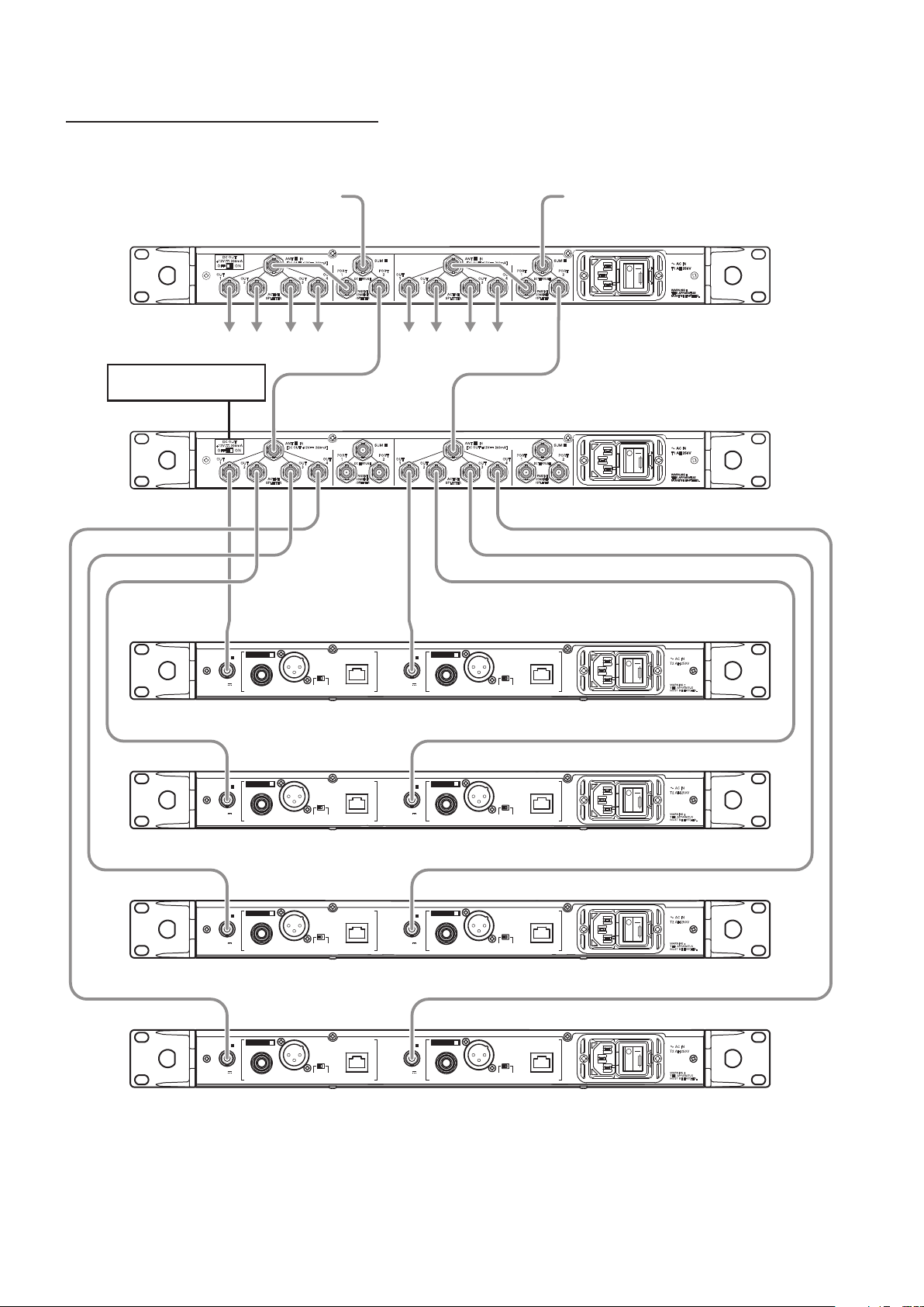
For maximum connection (when using 31 channels simultaneously)
External antenna External antenna
ATW-DA410
DC OUT
+12V 200mA
OFF ON
OUT
1
OUT
2
B A
ACTIVE
SPLITTER
ANT IN
[
DC OUT
+12V 200mA
OUT
3
]
PORT
OUT
4
B A
SUM
PORT
DC THROUGH
PASSIVE
COMBINER
/SPLITTER
OUT
2
1
1
To ATW-DA410 To ATW-DA410
Turn off the antenna power
switch on the second device.
DC OUT
+12V 200mA
OFF ON
OUT
1
OUT
2
B A
ACTIVE
SPLITTER
ANT IN
[
DC OUT
+12V 200mA
OUT
3
]
PORT
OUT
4
B A
SUM
PORT
DC THROUGH
PASSIVE
COMBINER
/SPLITTER
OUT
2
1
1
ANT IN
[
]
+12V 200mA
DC OUT
OUT
OUT
2
ACTIVE
SPLITTER
4
OUT
3
SUM
PORT
PORT
1
2
DC THROUGH
PASSIVE
COMBINER
/SPLITTER
max. 250V~ max. 250V~
ATW-DA410
ANT IN
[
]
+12V 200mA
DC OUT
OUT
OUT
2
ACTIVE
SPLITTER
4
OUT
3
SUM
PORT
PORT
1
2
DC THROUGH
PASSIVE
COMBINER
/SPLITTER
E
N
GROUND
GROUND
GROUND
GROUND
NETWORK
INTERFACE
GROUND
LIFT
NETWORK
INTERFACE
GROUND
LIFT
NETWORK
INTERFACE
GROUND
LIFT
NETWORK
INTERFACE
GROUND
LIFT
2
RECEIVER
ANT B ANT A
12V
60mA
ANT B ANT A
12V
60mA
ANT B ANT A
12V
60mA
ANT B ANT A
12V
60mA
RECEIVER
RECEIVER
RECEIVER
BALANCED
OUTPUT
2
BALANCED
OUTPUT
2
BALANCED
OUTPUT
2
BALANCED
OUTPUT
ATW-R6200 S
GROUND
NETWORK
INTERFACE
GROUND
LIFT
AC IN
T2 AH 250V
max. 250V~
:
WARNING
THIS APPARATUS
MUST BE EARTHED.
1
RECEIVER
12V
60mA
BALANCED
OUTPUT
ATW-R6200 S
GROUND
NETWORK
INTERFACE
GROUND
LIFT
AC IN
T2 AH 250V
max. 250V~
:
WARNING
THIS APPARATUS
MUST BE EARTHED.
1
RECEIVER
12V
60mA
BALANCED
OUTPUT
ATW-R6200 S
GROUND
NETWORK
INTERFACE
GROUND
LIFT
AC IN
T2 AH 250V
max. 250V~
:
WARNING
THIS APPARATUS
MUST BE EARTHED.
1
RECEIVER
12V
60mA
BALANCED
OUTPUT
ATW-R6200 S
GROUND
NETWORK
INTERFACE
GROUND
LIFT
AC IN
T2 AH 250V
max. 250V~
:
WARNING
THIS APPARATUS
MUST BE EARTHED.
1
RECEIVER
12V
60mA
BALANCED
OUTPUT
4
Page 6
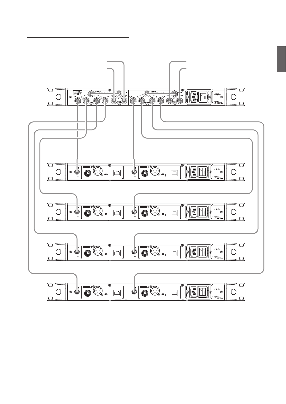
When using the 1:2 passive splitter section
External antenna External antenna
DC OUT
+12V 200mA
OFF ON
OUT
1
OUT
2
To ATW-R6200 S To ATW-R6200 S
Turn off the antenna power
switch on the second device.
DC OUT
+12V 200mA
OFF ON
OUT
1
OUT
2
B A
ANT IN
[
]
+12V 200mA
ACTIVE
SPLITTER
ACTIVE
SPLITTER
DC OUT
ANT IN
[
DC OUT
PORT
OUT
1
4
OUT
3
B A
+12V 200mA
OUT
3
DC THROUGH
PASSIVE
COMBINER
/SPLITTER
]
PORT
OUT
1
4
DC THROUGH
PASSIVE
COMBINER
/SPLITTER
B A
SUM
PORT
OUT
2
1
B A
SUM
PORT
OUT
2
1
ANT IN
[
]
+12V 200mA
DC OUT
OUT
2
ACTIVE
SPLITTER
ANT IN
[
DC OUT
OUT
2
ACTIVE
SPLITTER
OUT
3
+12V 200mA
OUT
3
PORT
OUT
1
4
DC THROUGH
]
PORT
OUT
1
4
DC THROUGH
PASSIVE
COMBINER
/SPLITTER
PASSIVE
COMBINER
/SPLITTER
ATW-DA410
SUM
PORT
2
max. 250V~ max. 250V~
ATW-DA410
SUM
PORT
2
GROUND
GROUND
GROUND
GROUND
NETWORK
INTERFACE
GROUND
LIFT
NETWORK
INTERFACE
GROUND
LIFT
NETWORK
INTERFACE
GROUND
LIFT
NETWORK
INTERFACE
GROUND
LIFT
2
RECEIVER
ANT B ANT A
12V
60mA
ANT B ANT A
12V
60mA
ANT B ANT A
12V
60mA
ANT B ANT A
12V
60mA
RECEIVER
RECEIVER
RECEIVER
BALANCED
OUTPUT
2
BALANCED
OUTPUT
2
BALANCED
OUTPUT
2
BALANCED
OUTPUT
ATW-R6200 S
GROUND
NETWORK
INTERFACE
GROUND
LIFT
AC IN
T2 AH 250V
max. 250V~
:
WARNING
THIS APPARATUS
MUST BE EARTHED.
1
RECEIVER
12V
60mA
BALANCED
OUTPUT
ATW-R6200 S
GROUND
NETWORK
INTERFACE
GROUND
LIFT
AC IN
T2 AH 250V
max. 250V~
:
WARNING
THIS APPARATUS
MUST BE EARTHED.
1
RECEIVER
12V
60mA
BALANCED
OUTPUT
ATW-R6200 S
GROUND
NETWORK
INTERFACE
GROUND
LIFT
AC IN
T2 AH 250V
max. 250V~
:
WARNING
THIS APPARATUS
MUST BE EARTHED.
1
RECEIVER
12V
60mA
BALANCED
OUTPUT
ATW-R6200 S
GROUND
NETWORK
INTERFACE
GROUND
LIFT
AC IN
T2 AH 250V
max. 250V~
:
WARNING
THIS APPARATUS
MUST BE EARTHED.
1
RECEIVER
12V
60mA
BALANCED
OUTPUT
* Accompanied by insertion loss in the 1:2 passive splitter section. Refer to "Specifications" for details.
* By connecting the PORT jacks to the ANT IN of channels A and B, 12 V DC of power can pass through (DC through current) to the SUM jack.
5
Page 7
When using the 2:1 passive combiner section
External antenna
External antenna
DC OUT
+12V 200mA
OFF ON
OUT
1
OUT
2
RECEIVER
ANT B ANT A
12V
60mA
B A
ACTIVE
SPLITTER
2
BALANCED
OUTPUT
ANT IN
[
DC OUT
+12V 200mA
OUT
3
GROUND
]
PORT
OUT
4
GROUND
LIFT
B A
SUM
PORT
1
2
DC THROUGH
PASSIVE
COMBINER
/SPLITTER
NETWORK
INTERFACE
External antenna
External antenna
ATW-DA410
ANT IN
[
]
+12V 200mA
OUT
1
OUT
12V
60mA
DC OUT
OUT
4
ACTIVE
SPLITTER
1
BALANCED
OUTPUT
OUT
3
GROUND
GROUND
LIFT
2
RECEIVER
SUM
PORT
PORT
1
2
DC THROUGH
PASSIVE
COMBINER
/SPLITTER
max. 250V~
ATW-R6200 S
NETWORK
INTERFACE
AC IN
T2 AH 250V
max. 250V~
:
WARNING
THIS APPARATUS
MUST BE EARTHED.
N
E
ATW-R6200 S
GROUND
NETWORK
INTERFACE
GROUND
LIFT
2
RECEIVER
ANT B ANT A
12V
60mA
BALANCED
OUTPUT
1
RECEIVER
12V
60mA
BALANCED
OUTPUT
GROUND
NETWORK
INTERFACE
GROUND
LIFT
AC IN
T2 AH 250V
max. 250V~
:
WARNING
THIS APPARATUS
MUST BE EARTHED.
ATW-R6200 S
GROUND
NETWORK
INTERFACE
GROUND
LIFT
2
RECEIVER
ANT B ANT A
12V
60mA
BALANCED
OUTPUT
1
RECEIVER
12V
60mA
BALANCED
OUTPUT
GROUND
NETWORK
INTERFACE
GROUND
LIFT
AC IN
T2 AH 250V
max. 250V~
:
WARNING
THIS APPARATUS
MUST BE EARTHED.
ATW-R6200 S
GROUND
NETWORK
INTERFACE
GROUND
LIFT
2
RECEIVER
ANT B ANT A
12V
60mA
BALANCED
OUTPUT
1
RECEIVER
12V
60mA
BALANCED
OUTPUT
GROUND
NETWORK
INTERFACE
GROUND
LIFT
AC IN
T2 AH 250V
max. 250V~
:
WARNING
THIS APPARATUS
MUST BE EARTHED.
* Accompanied by insertion loss in the 2:1 passive combiner section. Refer to "Specifications" for details.
* By connecting the SUM jack to the ANT IN of channels A and B, 12 V DC of power can pass through (DC through current) to the PORT 1 and 2 jacks.
When doing this, the total value of DC output from the PORT 1 and 2 jacks is a maximum of 200 mA for both channels.
6
Page 8
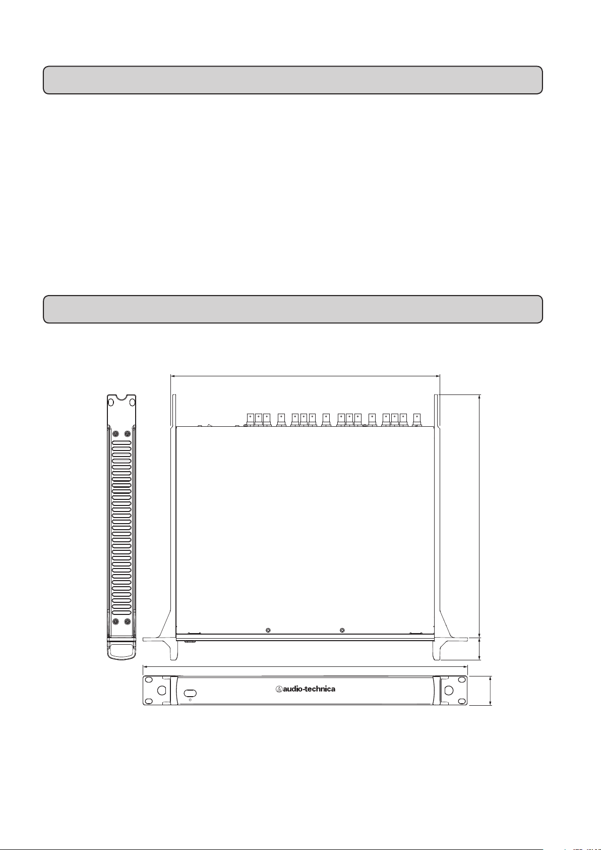
Specifications
470 to 990 MHz
Frequency range
Impedance
Antenna power supply
Power
Operating temperature range
Power consumption
External dimensions
(excluding protrusions)
Weight
Accessories
:
50 ohms
:
+12 V DC, max. 200 mA × 2
:
120 V AC 60 Hz
:
5°C to 45°C (41°F to 113 °F)
:
10 W
:
482 mm (18.97") × 43 mm (1.69") ×
:
361 mm (14.21") (W × H × D)
4.8 kg (10.6 lbs)
:
Power cable, BNC cable × 12,
:
BNC connector × 2
• This product is for use in the USA and Canada only.
• Specications are subject to change without prior notice.
1:4 Active splitter section
Distribution
System gain
Ripple
1:2 Passive splitter section/2:1 Passive combiner section
Splitter/combiner
Insertion loss
Dimensions
400
1-in / 4-out (BNC) x 2
:
0 dB typ.
:
± 3 dB
:
:
1: 2 (BNC) x 2
4 dB typ.
:
(Unit: mm)
ATW-DA410
470-990MHz
482
UHF ANTENNA DISTRIBUTION SYSTEM
361
32.8
43
7
Page 9

Memo
Page 10
Nous vous remercions d’avoir fait l’acquisition de ce produit.
Avant d’utiliser le produit, lisez attentivement le manuel de l’utilisateur afin d’utiliser correctement le produit. Gardez le
manuel ainsi que la garantie à portée de main afin de pouvoir les consulter ultérieurement.
Informations importantes
Avertissement:
• Afin d’éviter tout incendie ou tout danger d’électrocution, n’exposez
pas cet appareil à la pluie ou à l’humidité.
Précaution:
• N’exposez pas cet appareil aux gouttes d’eau ou éclaboussures.
• Pour éviter tout choc électrique, n’ouvrez pas l’armoire.
• Confiez toute réparation à un personnel qualifié uniquement.
• N’exposez pas cet appareil à une chaleur excessive telle que les
rayons du soleil, du feu, etc.
• Ne soumettez pas cet appareil à de forts impacts.
• Cet appareil doit être placé à proximité suffisante d’une prise
secteur afin de pouvoir facilement saisir la fiche d’alimentation à
tout moment.
• En cas d’urgence, débranchez rapidement la fiche d’alimentation de
l’appareil.
• Ne placez pas d’objets remplis de liquide, comme par exemple des
vases, sur l’appareil.
• Pour éviter tout incendie, ne placez pas de sources de flammes
nues (comme par exemple des bougies allumées) sur cet appareil.
• N’installez pas cet appareil dans un espace confiné comme par
exemple, une bibliothèque ou un objet similaire.
• Installez l’appareil uniquement dans des endroits présentant une
bonne ventilation.
• Pour éviter tout incendie, ne couvrez pas les évents de cet appareil
avec des papiers journaux, des nappes, des rideaux, etc.
• Cet appareil de construction Ιdoit être branché à une prise secteur
munie d’une protection de mise à la terre.
• Cet appareil n’est pas débranché du secteur tant qu’il est raccordé
à une prise secteur, même si l’unité elle-même a été mise hors
tension.
• L’étiquette signalétique se trouve sur le dessous de l’appareil.
Pour les clients aux États-Unis
notice UL/CSA
PRÉCAUTION
RISQUE DE CHOC ÉLECTRIQUE
NE PAS OUVRIR
Précaution:
couvercle. Certaines pièces à l’intérieur ne peuvent pas être réparées par
l’utilisateur. Les réglages internes ne peuvent être effectués que par des
professionnels qualifiés. Confiez toute réparation à du personnel qualifié.
Pour éviter tout choc électrique, n’enlevez pas le
La lumière clignotante avec un symbole en forme de tête de
flèche, dans un triangle équilatéral, est sensé avertir l’utilisateur
de la présence d’une “tension dangereuse” non isolée dans la
protection du produit qui peut être d’une magnitude suffisante
pour constituer un risque de chocs pour les personnes.
Le symbole représentant un point d’exclamation dans
un triangle équilatérale est sensé avertir l’utilisateur
de la présence d’instructions de maintenance
(entretien) et de fonctionnement importantes dans la
documentation accompagnant le produit.
Instructions de sécurité importantes
1. Lisez ces instructions.
2. Conservez ces instructions.
3. Tenez compte de tous les avertissements.
4. Suivez toutes les instructions.
5. N’utilisez pas cet appareil à proximité d’eau.
6. Nettoyez uniquement avec un chiffon sec.
7. Ne bloquez aucune ouverture d’aération. Procédez à
l’installation conformément aux instructions du fabricant.
8.
N’installez pas l’appareil à proximité de sources de chaleur telles
que des radiateurs, des bouches d’air chaud, des poêles ou autres
appareils (y compris des amplificateurs) qui génèrent de la chaleur.
9. Ne retirez en aucun cas le dispositif de sécurité de la fiche
polarisée ou de la fiche de terre. Une fiche polarisée possède
deux broches dont l’une est plus large que l’autre. Une fiche
de terre possède deux broches et une troisième de terre.
La large broche ou la troisième broche est fournie pour
votre sécurité. Si la fiche fournie ne convient pas à la prise,
consultez un électricien pour remplacer la prise.
1
0. Évitez de marcher ou de pincer le câble d’alimentation
particulièrement au niveau des fiches, de la prise de courant
et du point de sortie de l’appareil.
11. N’utilisez que les fixations/accessoires recommandés par le
fabricant.
12. N’utilisez que le chariot, le pied, le trépied,
le support ou la table recommandé par le
fabricant ou vendu avec l’appareil. Lorsqu’un
chariot est utilisé, faites attention lorsque vous
déplacez le chariot/appareil de ne pas vous
blesser car il pourrait basculer.
13. Débranchez l’appareil pendant des orages ou lorsqu’il n’est
pas utilisé pendant une période prolongée.
14. Confiez toute réparation à du personnel qualifié. Des
réparations sont nécessaires si l’appareil a été endommagé
d’une quelconque manière, endommagement du cordon
d’alimentation ou de la fiche par exemple, du liquide s’est
répandu ou des objets sont tombés dans l’appareil, l’appareil
a été exposé à la pluie ou à l’humidité, il ne fonctionne pas
normalement ou est tombé.
Notice FCC
Avertissement:
Cet appareil est conforme à la section 15 de la réglementation
FCC. Le fonctionnement est soumis aux deux conditions
suivantes: (1) cet appareil ne doit occasionner aucune
interférence nuisible, et (2) cet appareil doit accepter toute
interférence reçue, y compris l’interférence qui peut entraîner un
fonctionnement non souhaité.
Précaution:
Vous êtes averti que tout changement ou toute modification qui
n’est pas expressément approuvée dans ce manuel peut annuler
votre droit d’utiliser cet équipement.
Remarque: cet équipement a été testé et classé dans la
catégorie d’un appareil numérique de classe B, en accord
avec la partie 15 de la réglementation FCC. Ces limites sont
conçues pour garantir une protection raisonnable contre les
interférences nuisibles dans une installation résidentielle. Cet
équipement génère, utilise et peut émettre de l’énergie radio
électrique et, s’il n’est pas installé et utilisé conformément
aux instructions, peut occasionner des interférences nuisibles
aux communications radio. Il n’est toutefois pas garanti que
des interférences ne surviendront pas dans une installation
particulière. Si cet équipement occasionne des interférences
nuisibles à la réception radio ou de télévision, ce qui peut être
déterminé en mettant l’équipement hors et sous tension,
l’utilisateur est encouragé à tenter de corriger les interférences
en utilisant l’une ou plusieurs des mesures suivantes:
- Réorienter ou changer l’antenne de réception de place.
- Écarter davantage l’équipement du récepteur.
- Raccorder l’équipement dans une prise sur un circuit différent
de celui auquel est raccordé le récepteur.
- Consulter le revendeur ou un technicien radiotélévision
expérimenté pour obtenir de l’aide.
Pour les clients au Canada
déclaration d’industrie Canada (IC)
CAN ICES-3 (B)/NMB-3(B)
1
Page 11

Maintenance
max. 250V~
(2)
(8)(7)(6)(5)(4)(3)
(1)
• Lorsque vous débranchez le câble d’alimentation; si la che est sale ou poussiéreuse, nettoyez-la avec un chiffon doux et sec.
• N’utilisez pas de benzène ou de diluant à peinture pour nettoyer le produit.
•
Lors du rangement du produit pour une période prolongée, enveloppez le produit dans un plastique an de la protéger des poussières.
Remarques sur l’utilisation
• Le système sans fil peut être affecté par du bruit électromagnétique provenant des bougies de la voiture, des gradateurs
d’éclairage, des ordinateurs, des dispositifs OA ou des instruments électriques de musique. Positionnez les éléments du système
dans un endroit où ils seront moins susceptibles d’être affectés.
• N’utilisez cet appareil que combiné à des dispositifs spécifiés par le fabricant.
• Ne l’utilisez pas en dehors des États-Unis et du Canada. Une utilisation à l’étranger est punissable conformément à la législation
du pays pertinent.
•
Utilisez une source d’alimentation de 120 Vca 60 Hz. Reportez-vous aux “Caractéristiques Techniques” pour les évaluations de l’appareil.
Nomenclature et fonctions
Face avant
Face arrière
F
R
(1) Interrupteur
Appuyez sur l’interrupteur pour mettre l’appareil sous
tension.
Appuyez à nouveau sur l’interrupteur pour le mettre hors
tension.
L’interrupteur s’allume lorsque l’appareil est sous tension.
(2) Interrupteur de l’antenne
(hors tension lorsqu’il est livré de l’usine)
En allumant l’interrupteur, vous envoyez une tension de 12
Vcc vers ANT A IN ou ANT B IN (prises d’entrée d’antenne
pour les deux canaux A et B).
* L’alimentation ne peut pas être indépendamment fournie à ANT A IN ou
à ANT B IN.
(3)(5) 1:4 Section séparateur actif
ANT A IN, ANT B IN:
Ce sont les prises d’entrée d’antenne pour les canaux A et
B. En mettant l’appareil sous tension pour l’antenne, vous
donnez une tension d’alimentation de 12 Vcc.
OUT 1 à 4:
Ce sont les quatre prises de sortie de distribution pour les
canaux A et B.
(4)(6) 1:2 Section séparateur passif/2:1
Section combineur passif
Voici les sections distribution et combinaison pour les
canaux A et B.
Lors de l’entrée à la prise jack SUM, les signaux sont
distribués et proviennent du PORT 1 et des 2 prises jack.
Pour une entrée vers PORT 1 et les 2 prises jack, les
signaux sont combinés et proviennent de la prise jack SUM.
* La prise jack SUM et PORT 1 et les 2 prises jack supportent le courant
continu.
(7) Borne AC IN
Utilisez le connecteur de type IEC pour une puissance
d’entrée de 120 Vca 60 Hz.
• Ce produit est uniquement destiné aux clients résidant aux
États-Unis et au Canada. Il ne peut être utilisé à l’étranger.
(8) Commutateur principal
Appuyez sur le commutateur principal pour mettre l’appareil
sous tension.
Activez le commutateur principal avant d’allumer
l’interrupteur de la face avant.
2
Page 12

Méthodes de connexion (lors de la connexion à ATW-R6200 S)
Précautions lors de la connexion
• Assurez-vous de désactiver le paramètre d’alimentation de l’antenne sur le dispositif de réception auquel vous êtes connecté.
Pour les méthodes de configuration, reportez-vous au manuel de l’utilisateur du récepteur.
• Avant de raccorder une antenne externe, assurez-vous de mettre l’interrupteur de l’antenne hors tension.
Lors de l’alimentation électrique vers une antenne externe, connectez d’abord l’antenne, puis mettez l’interrupteur de l’antenne
sous tension.
Lors de la distribution de quatre signaux d’antenne
Antenne externe Antenne externe
ATW-DA410
DC OUT
+12V 200mA
OFF ON
OUT
1
B A
ANT IN
[
]
+12V 200mA
DC OUT
OUT
2
ACTIVE
SPLITTER
PORT
OUT
4
OUT
3
B A
SUM
PORT
DC THROUGH
PASSIVE
COMBINER
/SPLITTER
OUT
2
1
1
ANT IN
[
]
+12V 200mA
DC OUT
OUT
OUT
2
ACTIVE
SPLITTER
4
OUT
3
SUM
PORT
PORT
1
2
DC THROUGH
PASSIVE
COMBINER
/SPLITTER
max. 250V~
GROUND
GROUND
GROUND
GROUND
NETWORK
INTERFACE
GROUND
LIFT
NETWORK
INTERFACE
GROUND
LIFT
NETWORK
INTERFACE
GROUND
LIFT
NETWORK
INTERFACE
GROUND
LIFT
2
RECEIVER
ANT B ANT A
12V
60mA
ANT B ANT A
12V
60mA
ANT B ANT A
12V
60mA
ANT B ANT A
12V
60mA
RECEIVER
RECEIVER
RECEIVER
BALANCED
OUTPUT
2
BALANCED
OUTPUT
2
BALANCED
OUTPUT
2
BALANCED
OUTPUT
ATW-R6200 S
GROUND
NETWORK
INTERFACE
GROUND
LIFT
AC IN
T2 AH 250V
max. 250V~
:
WARNING
THIS APPARATUS
MUST BE EARTHED.
1
RECEIVER
12V
60mA
BALANCED
OUTPUT
ATW-R6200 S
GROUND
NETWORK
INTERFACE
GROUND
LIFT
AC IN
T2 AH 250V
max. 250V~
:
WARNING
THIS APPARATUS
MUST BE EARTHED.
1
RECEIVER
12V
60mA
BALANCED
OUTPUT
ATW-R6200 S
GROUND
NETWORK
INTERFACE
GROUND
LIFT
AC IN
T2 AH 250V
max. 250V~
:
WARNING
THIS APPARATUS
MUST BE EARTHED.
1
RECEIVER
12V
60mA
BALANCED
OUTPUT
ATW-R6200 S
GROUND
NETWORK
INTERFACE
GROUND
LIFT
AC IN
T2 AH 250V
max. 250V~
:
WARNING
THIS APPARATUS
MUST BE EARTHED.
1
RECEIVER
12V
60mA
BALANCED
OUTPUT
3
Page 13

Pour une connexion maximum (lors de l’utilisation de 31 chaînes simultanément)
Antenne externe Antenne externe
ATW-DA410
DC OUT
+12V 200mA
OFF ON
OUT
1
OUT
2
B A
ACTIVE
SPLITTER
ANT IN
[
DC OUT
+12V 200mA
OUT
3
]
PORT
OUT
4
B A
SUM
PORT
DC THROUGH
PASSIVE
COMBINER
/SPLITTER
OUT
2
1
1
Vers ATW-DA410 Vers ATW-DA410
Mettez l’interrupteur
d’alimentation de l’antenne
hors tension sur le deuxième
appareil.
DC OUT
+12V 200mA
OFF ON
OUT
1
OUT
2
B A
ACTIVE
SPLITTER
ANT IN
[
DC OUT
+12V 200mA
OUT
3
]
PORT
OUT
4
B A
SUM
PORT
DC THROUGH
PASSIVE
COMBINER
/SPLITTER
OUT
2
1
1
ANT IN
[
]
+12V 200mA
DC OUT
OUT
OUT
2
ACTIVE
SPLITTER
4
OUT
3
SUM
PORT
PORT
1
2
DC THROUGH
PASSIVE
COMBINER
/SPLITTER
max. 250V~ max. 250V~
ATW-DA410
ANT IN
[
]
+12V 200mA
DC OUT
OUT
OUT
2
ACTIVE
SPLITTER
4
OUT
3
SUM
PORT
PORT
1
2
DC THROUGH
PASSIVE
COMBINER
/SPLITTER
F
R
GROUND
GROUND
GROUND
GROUND
NETWORK
INTERFACE
GROUND
LIFT
NETWORK
INTERFACE
GROUND
LIFT
NETWORK
INTERFACE
GROUND
LIFT
NETWORK
INTERFACE
GROUND
LIFT
2
RECEIVER
ANT B ANT A
12V
60mA
ANT B ANT A
12V
60mA
ANT B ANT A
12V
60mA
ANT B ANT A
12V
60mA
RECEIVER
RECEIVER
RECEIVER
BALANCED
OUTPUT
2
BALANCED
OUTPUT
2
BALANCED
OUTPUT
2
BALANCED
OUTPUT
ATW-R6200 S
GROUND
NETWORK
INTERFACE
GROUND
LIFT
AC IN
T2 AH 250V
max. 250V~
:
WARNING
THIS APPARATUS
MUST BE EARTHED.
1
RECEIVER
12V
60mA
BALANCED
OUTPUT
ATW-R6200 S
GROUND
NETWORK
INTERFACE
GROUND
LIFT
AC IN
T2 AH 250V
max. 250V~
:
WARNING
THIS APPARATUS
MUST BE EARTHED.
1
RECEIVER
12V
60mA
BALANCED
OUTPUT
ATW-R6200 S
GROUND
NETWORK
INTERFACE
GROUND
LIFT
AC IN
T2 AH 250V
max. 250V~
:
WARNING
THIS APPARATUS
MUST BE EARTHED.
1
RECEIVER
12V
60mA
BALANCED
OUTPUT
ATW-R6200 S
GROUND
NETWORK
INTERFACE
GROUND
LIFT
AC IN
T2 AH 250V
max. 250V~
:
WARNING
THIS APPARATUS
MUST BE EARTHED.
1
RECEIVER
12V
60mA
BALANCED
OUTPUT
4
Page 14

Lors de l’utilisation de la section séparateur passif 1:2
Antenne externe Antenne externe
DC OUT
+12V 200mA
OFF ON
OUT
1
OUT
2
Vers ATW-R6200 S Vers ATW-R6200 S
Mettez l’interrupteur
d’alimentation de l’antenne
hors tension sur le deuxième
appareil.
DC OUT
+12V 200mA
OFF ON
OUT
1
OUT
2
B A
ANT IN
[
]
+12V 200mA
ACTIVE
SPLITTER
ACTIVE
SPLITTER
DC OUT
ANT IN
[
DC OUT
PORT
OUT
4
OUT
3
B A
]
+12V 200mA
PORT
OUT
4
OUT
3
B A
SUM
PORT
1
1
OUT
2
1
DC THROUGH
PASSIVE
COMBINER
/SPLITTER
B A
SUM
PORT
OUT
2
1
DC THROUGH
PASSIVE
COMBINER
/SPLITTER
OUT
2
OUT
2
ACTIVE
SPLITTER
ACTIVE
SPLITTER
ANT IN
[
DC OUT
ANT IN
[
DC OUT
+12V 200mA
OUT
3
+12V 200mA
OUT
3
ATW-DA410
SUM
]
PORT
OUT
4
PORT
1
2
DC THROUGH
PASSIVE
COMBINER
/SPLITTER
max. 250V~ max. 250V~
ATW-DA410
SUM
]
PORT
OUT
4
PORT
1
2
DC THROUGH
PASSIVE
COMBINER
/SPLITTER
GROUND
GROUND
GROUND
GROUND
NETWORK
INTERFACE
GROUND
LIFT
NETWORK
INTERFACE
GROUND
LIFT
NETWORK
INTERFACE
GROUND
LIFT
NETWORK
INTERFACE
GROUND
LIFT
2
RECEIVER
ANT B ANT A
12V
60mA
ANT B ANT A
12V
60mA
ANT B ANT A
12V
60mA
ANT B ANT A
12V
60mA
RECEIVER
RECEIVER
RECEIVER
BALANCED
OUTPUT
2
BALANCED
OUTPUT
2
BALANCED
OUTPUT
2
BALANCED
OUTPUT
ATW-R6200 S
GROUND
NETWORK
INTERFACE
GROUND
LIFT
AC IN
T2 AH 250V
max. 250V~
:
WARNING
THIS APPARATUS
MUST BE EARTHED.
1
RECEIVER
12V
60mA
BALANCED
OUTPUT
ATW-R6200 S
GROUND
NETWORK
INTERFACE
GROUND
LIFT
AC IN
T2 AH 250V
max. 250V~
:
WARNING
THIS APPARATUS
MUST BE EARTHED.
1
RECEIVER
12V
60mA
BALANCED
OUTPUT
ATW-R6200 S
GROUND
NETWORK
INTERFACE
GROUND
LIFT
AC IN
T2 AH 250V
max. 250V~
:
WARNING
THIS APPARATUS
MUST BE EARTHED.
1
RECEIVER
12V
60mA
BALANCED
OUTPUT
ATW-R6200 S
GROUND
NETWORK
INTERFACE
GROUND
LIFT
AC IN
T2 AH 250V
max. 250V~
:
WARNING
THIS APPARATUS
MUST BE EARTHED.
1
RECEIVER
12V
60mA
BALANCED
OUTPUT
* Accompagné d’une perte d’insertion dans la section séparateur passif 1:2. Reportez-vous aux “Caractéristiques Techniques” pour plus de détails.
* En connectant les prises jack PORT à la ANT IN des canaux A et B, une puissance de 12 Vcc peut traverser (courant traversant CC) pour atteindre la prise jack
SUM.
5
Page 15

Lors de l’utilisation de la section combineur passif 2:1
Antenne externe
Antenne externe
DC OUT
+12V 200mA
OFF ON
OUT
1
OUT
2
RECEIVER
ANT B ANT A
12V
60mA
RECEIVER
ANT B ANT A
12V
60mA
B A
ACTIVE
SPLITTER
2
BALANCED
OUTPUT
2
BALANCED
OUTPUT
ANT IN
[
DC OUT
+12V 200mA
OUT
3
GROUND
GROUND
]
PORT
OUT
4
GROUND
LIFT
GROUND
LIFT
B A
SUM
PORT
1
2
DC THROUGH
PASSIVE
COMBINER
/SPLITTER
NETWORK
INTERFACE
NETWORK
INTERFACE
Antenne externe
Antenne externe
ATW-DA410
ANT IN
[
]
+12V 200mA
OUT
1
OUT
DC OUT
OUT
4
ACTIVE
SPLITTER
OUT
3
2
SUM
PORT
PORT
1
2
DC THROUGH
PASSIVE
COMBINER
/SPLITTER
max. 250V~
ATW-R6200 S
GROUND
NETWORK
INTERFACE
GROUND
LIFT
AC IN
T2 AH 250V
max. 250V~
:
WARNING
THIS APPARATUS
MUST BE EARTHED.
1
RECEIVER
12V
60mA
BALANCED
OUTPUT
ATW-R6200 S
GROUND
NETWORK
INTERFACE
GROUND
LIFT
AC IN
T2 AH 250V
max. 250V~
:
WARNING
THIS APPARATUS
MUST BE EARTHED.
1
RECEIVER
12V
60mA
BALANCED
OUTPUT
F
R
ATW-R6200 S
GROUND
NETWORK
INTERFACE
GROUND
LIFT
2
RECEIVER
ANT B ANT A
12V
60mA
BALANCED
OUTPUT
1
RECEIVER
12V
60mA
BALANCED
OUTPUT
GROUND
NETWORK
INTERFACE
GROUND
LIFT
AC IN
T2 AH 250V
max. 250V~
:
WARNING
THIS APPARATUS
MUST BE EARTHED.
ATW-R6200 S
GROUND
NETWORK
INTERFACE
GROUND
LIFT
2
RECEIVER
ANT B ANT A
12V
60mA
BALANCED
OUTPUT
1
RECEIVER
12V
60mA
BALANCED
OUTPUT
GROUND
NETWORK
INTERFACE
GROUND
LIFT
AC IN
T2 AH 250V
max. 250V~
:
WARNING
THIS APPARATUS
MUST BE EARTHED.
* Accompagné d’une perte d’insertion dans la section combineur passif 2:1. Reportez-vous aux “Caractéristiques Techniques” pour plus de détails.
* En connectant la prise jack SUM à la ANT IN des canaux A et B, une puissance de 12 Vcc peut traverser (courant traversant CC) pour atteindre le PORT 1 et
les 2 prises jack. La valeur totale de sortie CC depuis le PORT 1 et les 2 prises jack est alors de 200 mA maximum pour les deux canaux.
6
Page 16

Caractéristiques Techniques
Plage de fréquence
Impédance
Alimentation électrique
d’antenne
Puissance
Plage de température de
fonctionnement
Consommation électrique
Dimensions externes (sans
les saillies)
Poids
Accessoires
:
470 à 990 MHz
50 ohms
:
+12 Vcc, 200 mA max × 2
:
120 Vca 60 Hz
:
5°C à 45°C
:
10 W
:
482 mm × 43 mm × 361 mm
:
(P × L × l)
4,8 kg
:
Câble d’alimentation, câble BNC
:
1:4 Section séparateur actif
Distribution
Gain du système
Ondulation
1:2 section séparateur passif/2:1 Section combineur
passif
Séparateur/combineur
Perte d’insertion
× 12, connecteur BNC × 2
• Ce produit est destiné aux clients résidant aux États-Unis et au Canada uniquement.
• Les caractéristiques techniques sont soumises à des changements sans en avertir au préalable.
Dimensions
400
1-entrée / 4-sortie (BNC)
:
x 2
0 dB typ.
:
± 3 dB
:
:
1: 2 (BNC) x 2
4 dB typ.
:
(Unité: mm)
ATW-DA410
470-990MHz
482
UHF ANTENNA DISTRIBUTION SYSTEM
361
32.8
43
7
Page 17

Memo
Page 18

Gracias por comprar este producto.
Antes de utilizar el producto, dedique un tiempo a leer este manual del usuario detenidamente para garantizar el uso
correcto del producto. Asimismo, tenga este manual del usuario a mano, junto con la garantía, para poder consultarlos en
cualquier momento.
Información importante
Advertencia:
• Para evitar el peligro de incendio o de descarga eléctrica, no
exponga este equipo a la lluvia o a la humedad.
Precaución:
• No exponga este equipo a goteos o salpicaduras.
• Para evitar descargas eléctricas, no abra la carcasa.
• Confíe las reparaciones únicamente a personal cualificado.
• No exponga este equipo a un exceso de calor. como la luz directa
del sol, el fuego o similares.
• No someta este equipo a fuertes impactos.
•
Este equipo debe situarse cerca de una toma de CA, de forma que permita
asir el enchufe del cable de alimentación con facilidad en cualquier momento.
• En caso de emergencia, desconecte inmediatamente el enchufe del
cable de alimentación del equipo.
•
No coloque objetos que contengan líquido, como jarrones, sobre este equipo.
• Para evitar incendios, no coloque fuentes de llamas sin protección
(como velas) sobre este equipo.
• No instale este equipo en espacios confinados, como una estantería
de libros o similar.
• Instálelo únicamente en lugares con buena ventilación.
• Para evitar incendios, no tape la rejilla de ventilación de este equipo
con periódicos, manteles, cortinas, etc.
• Este equipo de construcción Clase Ιdebe conectarse a una toma
de CA dotada de protección a tierra.
•
Este equipo no está desconectado de la red eléctrica mientras esté conectado
a una toma de CA, aunque se haya apagado la unidad propiamente dicha.
• La etiqueta de especificaciones eléctricas está situada en la parte
inferior de este equipo.
Para clientes en EE.UU.
Declaración de la UL/CSA
PRECAUCIÓN
RIESGO DE DESCARGA ELÉCTRICA
Precaución: Para evitar descargas eléctricas, no retire la tapa.
No hay piezas que puedan ser sustituidas por el usuario en el
interior. Los ajustes internos deben ser realizados únicamente
por profesionales cualificados. Confíe todas las reparaciones
únicamente a personal técnico cualificado.
El símbolo del relámpago con cabeza de flecha dentro
de un triángulo equilátero tiene por objeto alertar al
usuario de la presencia de “tensión peligrosa” no
aislada en el interior de la caja del producto que puede
ser de una magnitud suficiente como para constituir
un riesgo de descarga para las personas.
El símbolo de exclamación dentro de un triángulo
equilátero tiene por objeto alertar al usuario de la
presencia de instrucciones de uso y mantenimiento
(reparación) importantes en la literatura que acompaña
al producto.
NO ABRIR
Instrucciones importantes de seguridad
1. Lea estas instrucciones.
2. Guarde estas instrucciones.
3. Preste atención a todas las advertencias.
4. Siga todas las instrucciones.
5. No utilice este equipo cerca del agua.
6. Límpielo con un paño seco únicamente.
7. No obstruya las aberturas de ventilación. Realice la instalación
siguiendo las instrucciones del fabricante.
8. No instale el equipo cerca de fuentes de calor como
radiadores, trampillas de la calefacción, estufas u otros
aparatos (incluidos amplificadores) que generen calor.
9. No frustre la función de seguridad del enchufe polarizado
o tipo toma a tierra. Los enchufes polarizados poseen dos
palas, una más ancha que la otra. Los enchufes tipo toma a
tierra poseen dos palas y una tercera patilla de toma a tierra.
La pala más ancha o la tercera patilla se proveen para su
seguridad. Si el enchufe suministrado no encaja en la toma
de corriente, consulte a un electricista para proceder a la
sustitución de la toma obsoleta.
10. Proteja el cable de alimentación de pisadas o pinzamientos,
en particular en los enchufes, las tomas de corriente
múltiples y en el punto en que salen del equipo.
11. Utilice únicamente los complementos/accesorios
especificados por el fabricante.
12. Utilícelo únicamente con una carretilla, soporte,
trípode, repisa o mesa especificada por el
fabricante, o que se venda con el equipo. Si se
utiliza una carretilla, tenga cuidado al desplazar
la combinación carretilla/equipo para evitar
lesiones derivadas de vuelcos.
13. Desenchufe este equipo durante las tormentas eléctricas o
cuando no se vaya a utilizar durante un periodo prolongado
de tiempo.
14. Confíe todas las reparaciones únicamente a personal técnico
cualificado. El equipo deberá ser reparado si ha sufrido
algún tipo de daño, como que se haya dañado el cable de
alimentación o el enchufe, se haya derramado líquido o hayan
caído objetos en el interior del mismo, que haya estado
expuesto a la lluvia o a la humedad, que no funcione con
normalidad o haya sufrido alguna caída.
Declaración de la FCC
Advertencia:
Este dispositivo cumple con la Parte 15 de las Reglas de la FCC.
Su funcionamiento está sujeto a las dos condiciones siguientes:
(1) que este dispositivo no cause interferencias perjudiciales,
y (2) que este dispositivo acepte obligatoriamente cualquier
interferencia que reciba, incluida aquella que pueda producir un
funcionamiento no deseado.
Precaución:
Se le advierte que los cambios o modificaciones no aprobados
expresamente en este manual podrían invalidar la autorización
para utilizar este equipo.
Nota: Este equipo ha sido sometido a pruebas y se ha
determinado que cumple con los límites establecidos para
dispositivos digitales de Clase B, de acuerdo con la Parte 15
de las Reglas de la FCC. Estos límites están diseñador para
dar protección razonable contra interferencias perjudiciales en
una instalación residencial. Este equipo genera, utiliza y puede
irradiar energía de radio frecuencia y si no se instala y usa
con arreglo a las instrucciones, puede producir interferencias
perjudiciales a las comunicaciones por radio. No obstante, no
se garantiza la ausencia de interferencias en una instalación
concreta. Si este equipo provoca interferencias perjudiciales a la
recepción de radio o de televisión, lo cual se puede determinar
apagando y encendiendo el quipo, se recomienda al usuario
intentar corregir dichas interferencias adoptando una o varias de
las medidas siguientes:
- Reoriente o recoloque la antena receptora.
- Aumente la distancia entre el equipo y el receptor.
- Conecte el equipo a una toma de corriente de un circuito
distinto al que se halle conectado el receptor.
- Consulte al distribuidor o a un técnico de radio o televisión
cualificado.
Para clientes en Canadá
Declaración de la IC
CAN ICES-3 (B)/NMB-3(B)
1
Page 19

Mantenimiento
max. 250V~
(2)
(8)(7)(6)(5)(4)(3)
(1)
• Si al desconectar el cable de alimentación, el enchufe está sucio o tiene polvo, límpielo con un paño suave y seco.
• No utilice sustancias como benceno o disolvente para limpiar el producto.
• Cuando vaya a guardar el producto durante un periodo prolongado de tiempo, envuélvalo en plástico para protegerlo del polvo.
Notas acerca del uso
• El sistema inalámbrico es sensible al ruido electromagnético generado por bujías de automóvil, reguladores de intensidad de luz,
ordenadores, dispositivos de OA o instrumentos musicales eléctricos. Coloque los componentes del sistema en un lugar donde
estén menos expuestos a interferencias.
• Utilice este producto únicamente junto con aquellos dispositivos especificados por el fabricante.
• No utilice este equipo fuera de EE.UU. y Canadá. Su uso en el extranjero puede estar sujeto a penalización según las leyes del
país en cuestión.
•
Utilice una fuente de alimentación de 120 V CA 60 Hz. Consulte “Especificaciones” para conocer las características eléctricas del producto.
Identificación y función de las piezas
Panel frontal
E
S
(1) Interruptor de encendido
Pulse el interruptor para conectar la alimentación.
Pulse el interruptor de nuevo para desconectar la alimentación.
El interruptor de encendido se ilumina cuando se conecta la
alimentación.
(2) Interruptor de alimentación de la
antena
Al conectar este interruptor, se suministran 12 V CC a las
tomas ANT A IN o ANT B IN (tomas de entrada de la antena
para los canales A y B).
*
No se puede suministrar energía por separado a ANT A IN o a ANT B IN.
(desconectado al salir de fábrica)
(3)(5) Sección del separador activo 1:4
ANT A IN, ANT B IN:
Estas son las tomas de entrada de antena para los canales
A y B. Al conectar el interruptor de alimentación de la
antena, se suministran 12 V CC.
OUT 1 a 4:
Estas son cuatro tomas de salida de distribución para los
canales A y B.
Panel trasero
(4)(6) Sección del separador pasivo 1:2/
Sección del combinador pasivo 2:1
Estas secciones de distribución y combinación están
destinadas a los canales A y B.
Cuando se reciben a través de la toma SUM, las señales
son distribuidas y salen por las tomas PORT 1 y 2.
Cuando se reciben a través de las tomas PORT 1 y 2, las
señales son combinadas y salen por la toma SUM.
* La toma SUM y las tomas PORT 1 y 2 admiten corrientes CC de paso.
(7) Terminal AC IN
Utilice el conector tipo IEC para una potencia de entrada de
120 V CA 60 Hz.
• Este producto está concebido para su uso en EE.UU. y Canadá
exclusivamente. No debe utilizarse fuera de estos países.
(8) Interruptor principal
Pulse el interruptor principal para conectar la alimentación.
Pulse el interruptor principal antes de activar el interruptor
de encendido del panel frontal.
2
Page 20

Métodos de conexión (cuando se conecta al ATW-R6200 S)
Precauciones durante la conexión
• Desactive el ajuste de alimentación eléctrica de la antena en el dispositivo receptor al que se vaya a conectar.
Consulte los métodos de configuración en el manual del usuario del receptor.
• Antes de conectar una antena externa, asegúrese bien de que el interruptor de alimentación de la antena está desconectado.
Cuando vaya a suministrar alimentación eléctrica a una antena externa, conecte primero la antena y luego conecte el interruptor
de alimentación de la antena.
Distribución de las señales de cuatro antenas
Antena externa Antena externa
ATW-DA410
DC OUT
+12V 200mA
OFF ON
OUT
1
B A
ANT IN
[
]
+12V 200mA
DC OUT
OUT
2
ACTIVE
SPLITTER
PORT
OUT
4
OUT
3
B A
SUM
PORT
DC THROUGH
PASSIVE
COMBINER
/SPLITTER
OUT
2
1
1
ANT IN
[
]
+12V 200mA
DC OUT
OUT
OUT
2
ACTIVE
SPLITTER
4
OUT
3
SUM
PORT
PORT
1
2
DC THROUGH
PASSIVE
COMBINER
/SPLITTER
max. 250V~
GROUND
GROUND
GROUND
GROUND
NETWORK
INTERFACE
GROUND
LIFT
NETWORK
INTERFACE
GROUND
LIFT
NETWORK
INTERFACE
GROUND
LIFT
NETWORK
INTERFACE
GROUND
LIFT
2
RECEIVER
ANT B ANT A
12V
60mA
ANT B ANT A
12V
60mA
ANT B ANT A
12V
60mA
ANT B ANT A
12V
60mA
RECEIVER
RECEIVER
RECEIVER
BALANCED
OUTPUT
2
BALANCED
OUTPUT
2
BALANCED
OUTPUT
2
BALANCED
OUTPUT
ATW-R6200 S
GROUND
NETWORK
INTERFACE
GROUND
LIFT
AC IN
T2 AH 250V
max. 250V~
:
WARNING
THIS APPARATUS
MUST BE EARTHED.
1
RECEIVER
12V
60mA
BALANCED
OUTPUT
ATW-R6200 S
GROUND
NETWORK
INTERFACE
GROUND
LIFT
AC IN
T2 AH 250V
max. 250V~
:
WARNING
THIS APPARATUS
MUST BE EARTHED.
1
RECEIVER
12V
60mA
BALANCED
OUTPUT
ATW-R6200 S
GROUND
NETWORK
INTERFACE
GROUND
LIFT
AC IN
T2 AH 250V
max. 250V~
:
WARNING
THIS APPARATUS
MUST BE EARTHED.
1
RECEIVER
12V
60mA
BALANCED
OUTPUT
ATW-R6200 S
GROUND
NETWORK
INTERFACE
GROUND
LIFT
AC IN
T2 AH 250V
max. 250V~
:
WARNING
THIS APPARATUS
MUST BE EARTHED.
1
RECEIVER
12V
60mA
BALANCED
OUTPUT
3
Page 21

Para máxima conexión (cuando se utilizan 31 canales simultáneamente)
Antena externa Antena externa
DC OUT
+12V 200mA
OFF ON
OUT
1
B A
ANT IN
[
]
+12V 200mA
DC OUT
OUT
2
ACTIVE
SPLITTER
PORT
OUT
4
OUT
3
B A
SUM
PORT
DC THROUGH
PASSIVE
COMBINER
/SPLITTER
OUT
2
1
1
ANT IN
[
]
+12V 200mA
DC OUT
OUT
OUT
2
ACTIVE
SPLITTER
4
OUT
3
SUM
PORT
PORT
1
2
DC THROUGH
PASSIVE
COMBINER
/SPLITTER
ATW-DA410
max. 250V~ max. 250V~
A ATW-DA410 A ATW-DA410
Desconecte el interruptor de
alimentación eléctrica de la
antena en el segundo
dispositivo.
DC OUT
+12V 200mA
OFF ON
OUT
1
B A
ANT IN
[
]
+12V 200mA
DC OUT
OUT
2
ACTIVE
SPLITTER
PORT
OUT
4
OUT
3
B A
SUM
PORT
DC THROUGH
PASSIVE
COMBINER
/SPLITTER
OUT
2
1
1
ANT IN
[
]
+12V 200mA
DC OUT
OUT
OUT
2
ACTIVE
SPLITTER
4
OUT
3
SUM
PORT
PORT
1
2
DC THROUGH
PASSIVE
COMBINER
/SPLITTER
ATW-DA410
ATW-R6200 S
GROUND
NETWORK
INTERFACE
GROUND
LIFT
2
RECEIVER
ANT B ANT A
12V
60mA
BALANCED
OUTPUT
1
RECEIVER
12V
60mA
BALANCED
OUTPUT
GROUND
NETWORK
INTERFACE
GROUND
LIFT
AC IN
T2 AH 250V
max. 250V~
:
WARNING
THIS APPARATUS
MUST BE EARTHED.
E
S
GROUND
GROUND
GROUND
NETWORK
INTERFACE
GROUND
LIFT
NETWORK
INTERFACE
GROUND
LIFT
NETWORK
INTERFACE
GROUND
LIFT
2
RECEIVER
ANT B ANT A
12V
60mA
ANT B ANT A
12V
60mA
ANT B ANT A
12V
60mA
RECEIVER
RECEIVER
BALANCED
OUTPUT
2
BALANCED
OUTPUT
2
BALANCED
OUTPUT
ATW-R6200 S
GROUND
NETWORK
INTERFACE
GROUND
LIFT
AC IN
T2 AH 250V
max. 250V~
:
WARNING
THIS APPARATUS
MUST BE EARTHED.
1
RECEIVER
12V
60mA
BALANCED
OUTPUT
ATW-R6200 S
GROUND
NETWORK
INTERFACE
GROUND
LIFT
AC IN
T2 AH 250V
max. 250V~
:
WARNING
THIS APPARATUS
MUST BE EARTHED.
1
RECEIVER
12V
60mA
BALANCED
OUTPUT
ATW-R6200 S
GROUND
NETWORK
INTERFACE
GROUND
LIFT
AC IN
T2 AH 250V
max. 250V~
:
WARNING
THIS APPARATUS
MUST BE EARTHED.
1
RECEIVER
12V
60mA
BALANCED
OUTPUT
4
Page 22

Uso de la sección del separador pasivo 1:2
Antena externa Antena externa
DC OUT
+12V 200mA
OFF ON
OUT
1
A ATW-R6200 S A ATW-R6200 S
Desconecte el interruptor de
alimentación eléctrica de la
antena en el segundo dispositivo.
DC OUT
+12V 200mA
OFF ON
OUT
1
OUT
2
OUT
2
B A
ANT IN
[
]
+12V 200mA
ACTIVE
SPLITTER
ACTIVE
SPLITTER
DC OUT
ANT IN
[
DC OUT
PORT
OUT
1
4
OUT
3
B A
+12V 200mA
OUT
3
DC THROUGH
PASSIVE
COMBINER
/SPLITTER
]
PORT
OUT
1
4
DC THROUGH
PASSIVE
COMBINER
/SPLITTER
B A
SUM
PORT
OUT
2
1
B A
SUM
PORT
OUT
2
1
ANT IN
[
]
+12V 200mA
DC OUT
OUT
2
ACTIVE
SPLITTER
ANT IN
[
DC OUT
OUT
2
ACTIVE
SPLITTER
OUT
3
+12V 200mA
OUT
3
PORT
OUT
1
4
DC THROUGH
]
PORT
OUT
1
4
DC THROUGH
PASSIVE
COMBINER
/SPLITTER
PASSIVE
COMBINER
/SPLITTER
ATW-DA410
SUM
PORT
2
max. 250V~ max. 250V~
ATW-DA410
SUM
PORT
2
GROUND
GROUND
GROUND
GROUND
NETWORK
INTERFACE
GROUND
LIFT
NETWORK
INTERFACE
GROUND
LIFT
NETWORK
INTERFACE
GROUND
LIFT
NETWORK
INTERFACE
GROUND
LIFT
2
RECEIVER
ANT B ANT A
12V
60mA
ANT B ANT A
12V
60mA
ANT B ANT A
12V
60mA
ANT B ANT A
12V
60mA
RECEIVER
RECEIVER
RECEIVER
BALANCED
OUTPUT
2
BALANCED
OUTPUT
2
BALANCED
OUTPUT
2
BALANCED
OUTPUT
ATW-R6200 S
GROUND
NETWORK
INTERFACE
GROUND
LIFT
AC IN
T2 AH 250V
max. 250V~
:
WARNING
THIS APPARATUS
MUST BE EARTHED.
1
RECEIVER
12V
60mA
BALANCED
OUTPUT
ATW-R6200 S
GROUND
NETWORK
INTERFACE
GROUND
LIFT
AC IN
T2 AH 250V
max. 250V~
:
WARNING
THIS APPARATUS
MUST BE EARTHED.
1
RECEIVER
12V
60mA
BALANCED
OUTPUT
ATW-R6200 S
GROUND
NETWORK
INTERFACE
GROUND
LIFT
AC IN
T2 AH 250V
max. 250V~
:
WARNING
THIS APPARATUS
MUST BE EARTHED.
1
RECEIVER
12V
60mA
BALANCED
OUTPUT
ATW-R6200 S
GROUND
NETWORK
INTERFACE
GROUND
LIFT
AC IN
T2 AH 250V
max. 250V~
:
WARNING
THIS APPARATUS
MUST BE EARTHED.
1
RECEIVER
12V
60mA
BALANCED
OUTPUT
* Con pérdida de inserción en la sección del separador pasivo 1:2. Consulte “Especificaciones” para más información.
* Al conectar las tomas PORT a la toma ANT IN de los canales A y B, puede pasar 12 V CC de potencia (corriente CC de paso) hasta la toma SUM.
5
Page 23

Uso de la sección del combinador pasivo 2:1
Antena externa
Antena externa
DC OUT
+12V 200mA
OFF ON
OUT
1
OUT
2
RECEIVER
ANT B ANT A
12V
60mA
RECEIVER
ANT B ANT A
12V
60mA
B A
ACTIVE
SPLITTER
2
BALANCED
OUTPUT
2
BALANCED
OUTPUT
ANT IN
[
DC OUT
+12V 200mA
OUT
3
GROUND
GROUND
]
PORT
OUT
4
GROUND
LIFT
GROUND
LIFT
B A
SUM
PORT
1
2
DC THROUGH
PASSIVE
COMBINER
/SPLITTER
NETWORK
INTERFACE
NETWORK
INTERFACE
Antena externa
Antena externa
ATW-DA410
ANT IN
[
]
+12V 200mA
OUT
1
OUT
DC OUT
OUT
4
ACTIVE
SPLITTER
OUT
3
2
SUM
PORT
PORT
1
2
DC THROUGH
PASSIVE
COMBINER
/SPLITTER
max. 250V~
E
S
ATW-R6200 S
GROUND
GROUND
NETWORK
INTERFACE
GROUND
LIFT
AC IN
T2 AH 250V
max. 250V~
:
WARNING
THIS APPARATUS
MUST BE EARTHED.
ATW-R6200 S
NETWORK
INTERFACE
GROUND
LIFT
AC IN
T2 AH 250V
max. 250V~
:
WARNING
THIS APPARATUS
MUST BE EARTHED.
1
RECEIVER
12V
60mA
12V
60mA
RECEIVER
BALANCED
OUTPUT
1
BALANCED
OUTPUT
ATW-R6200 S
GROUND
NETWORK
INTERFACE
GROUND
LIFT
2
RECEIVER
ANT B ANT A
12V
60mA
BALANCED
OUTPUT
1
RECEIVER
12V
60mA
BALANCED
OUTPUT
GROUND
NETWORK
INTERFACE
GROUND
LIFT
AC IN
T2 AH 250V
max. 250V~
:
WARNING
THIS APPARATUS
MUST BE EARTHED.
ATW-R6200 S
GROUND
NETWORK
INTERFACE
GROUND
LIFT
2
RECEIVER
ANT B ANT A
12V
60mA
BALANCED
OUTPUT
1
RECEIVER
12V
60mA
BALANCED
OUTPUT
GROUND
NETWORK
INTERFACE
GROUND
LIFT
AC IN
T2 AH 250V
max. 250V~
:
WARNING
THIS APPARATUS
MUST BE EARTHED.
* Con pérdida de inserción en la sección del combinador pasivo 2:1. Consulte “Especificaciones” para más información.
* Al conectar la toma SUM a la toma ANT IN de los canales A y B, puede pasar 12 V CC de potencia (corriente CC de paso) hasta las tomas PORT 1 y 2.
Al hacerlo, el valor total de salida de CC a través de las tomas PORT 1 y 2 es de un máximo de 200 mA para ambos canales.
6
Page 24

Especificaciones
:
Rango de frecuencias
Impedancia
Suministro eléctrico de la
antena
Potencia
Rango de temperaturas de
servicio
Consumo
Dimensiones externas
(sin incluir los salientes)
Peso
Accesorios
De 470 a 990 MHz
50 ohmios
:
+12 V CC, máx. 200 mA × 2
:
120 V CA 60 Hz
:
De 5°C a 45°C
:
10 W
:
482 mm × 43 mm × 361 mm
:
(An × Al × Pr)
4,8 kg
:
Cable de alimentación, cable
:
BNC × 12, conector BNC × 2
• Este producto está concebido para su uso en EE.UU. y Canadá exclusivamente.
• Las especicaciones está sujetas a cambio sin previo aviso.
Dimensiones
Sección del separador activo 1:4
Distribución
Ganancia del sistema
Ondulación
Sección del separador pasivo 1:2/
Sección del combinador pasivo 2:1
Separador/combinador
Pérdida de inserción
400
1-entrada / 4-salida
:
(BNC) x 2
0 dB típ.
:
± 3 dB
:
:
1: 2 (BNC) x 2
4 dB típ.
:
(Unidad: mm)
ATW-DA410
470-990MHz
482
UHF ANTENNA DISTRIBUTION SYSTEM
361
32.8
43
7
Page 25

Memo
Page 26

Obrigado por comprar este produto.
Antes de usar o produto, leia com atenção o manual de usuário para assegurar que você irá usar corretamente o produto.
Guarde este manual de usuário em local apropriado e de fácil alcance, junto com a garantia, para estarem sempre
disponíveis para consulta.
Informação importante
Advertência:
• Para evitar incêndio ou choque elétrico, não exponha este aparelho a
chuva ou umidade.
Atenção:
• Não exponha este aparelho a pingos ou salpicos.
• Para evitar choque elétrico, não abra a caixa.
• O serviço só deve ser feito por pessoal qualificado.
• Não exponha este aparelho a calor excessivo como luz solar,
incêndio ou situação semelhante.
• Não deixe que este aparelho sofra batidas fortes.
• Este aparelho deve estar próximo suficiente da tomada de AC para
poder agarrar facilmente o plugue do cabo de alimentação.
• Em caso de emergência, desconecte rapidamente o plugue do cabo
de alimentação deste aparelho.
• Não coloque quaisquer objetos cheios com líquidos, como vasos,
sobre este aparelho.
• Para prevenir incêndios, não coloque fontes de chama nua (como
velas acesas) sobre este aparelho.
• Não instale este aparelho num espaço confinado como uma estante
para livros ou local semelhante.
• Instale este aparelho apenas em locais com boa ventilação.
• Para prevenir incêndios, não cubra as aberturas de ventilação deste
aparelho com jornais, panos de mesa, cortinas, etc.
• Este aparelho com uma construção classe I deve ser conectado a
uma tomada com aterramento de proteção.
• Este aparelho não é desconectado da rede elétrica enquanto estiver
conectado a uma tomada, mesmo se a unidade for desligada.
• A etiqueta de classificação está na parte inferior deste aparelho.
Para clientes nos EUA
Aviso UL/CSA
ATENÇÃO
RISCO DE CHOQUE ELÉTRICO
Atenção:
dos elementos internos pode ser reparado pelo utilizador. Apenas
profissionais devidamente habilitados podem fazer ajustes internos.
Recorra aos serviços de pessoal qualificado.
Para prevenir choque elétrico, não remova a tampa. Nenhum
A luz piscando com o símbolo de ponta de seta, dentro de
um triângulo equilátero, alerta o usuário para a presença
de “voltagens perigosas” não isoladas dentro da caixa do
produto que podem constituir risco de choque elétrico para
pessoas.
O símbolo do ponto de exclamação dentro de um
triângulo equilátero, alerta o usuário para a presença
de instruções de operação e manutenção (serviço) na
literatura junta ao produto.
NÃO ABRIR
Instruções de segurança importantes
1. Leia estas instruções.
2. Guarde estas instruções.
3. Respeite todas as advertências.
4. Siga todas as instruções.
5. Não use este aparelho perto de água.
6. Limpe apenas com um pano seco.
7. Não cubra as aberturas de ventilação. Faça a instalação
seguindo as instruções do fabricante.
8. Não instale junto de fontes de calor como radiadores, registros
de calor, fogões ou outros aparelhos (incluindo amplificadores)
que geram calor.
9. Não contrarie o propósito de segurança do plugue polarizado
ou com aterramento. Um plugue polarizado tem duas lâminas
com uma mais larga que a outra. Um plugue com aterramento
tem duas lâminas e um terceiro pino de aterramento. A
lâmina mais larga ou o terceiro pino são para sua segurança.
Se o plugue fornecido não encaixar na tomada, consulte um
eletricista para fazer a substituição da tomada obsoleta.
10. Proteja o cabo de alimentação para não ser pisado ou
entalado especialmente junto dos plugues, caixas de ligação
e o ponto de saída do aparelho.
11.
Use apenas ligações/acessórios especificados pelo fabricante.
12. Use apenas com um carro, base, tripé, suporte
ou mesa especificado pelo fabricante ou vendido
com o aparelho. Quando usar um carro, tenha
cuidado ao deslocar o conjunto do carro/aparelho
para evitar ferimentos em caso de queda.
13. Desconecte este aparelho durante tempestades elétricas ou
quando não vai ser usado durante longos períodos.
14. Recorra aos serviços de pessoal qualificado. A assistência
é necessária quando o aparelho for danificado de alguma
forma, tal como se o cabo de alimentação ou o plugue for
danificado ou se for entornado qualquer líquido, caírem objetos
para dentro do aparelho, o aparelho for exposto à chuva ou
umidade, se não funcionar normalmente ou se tiver caído.
Aviso da FCC
Advertência:
Este dispositivo está em conformidade com a Parte 15 das
Regras da FCC. A operação está sujeita às seguintes duas
condições: (1) Este dispositivo não pode causar interferências
nocivas, e (2) este dispositivo deve aceitar qualquer interferência
recebida, incluindo interferências que possam causar operação
indesejada.
Atenção:
Fica avisado de que quaisquer alterações ou modificações
não expressamente aprovadas neste manual podem anular a
autoridade do usuário para operar este equipamento.
Nota: Este equipamento foi testado e obedece aos limites
estabelecidos para um dispositivo digital Classe B, segundo
a Parte 15 das Regras da FCC. Esses limites destinam-se a
fornecer uma proteção razoável contra interferências nocivas
numa instalação doméstica. Este equipamento gera, usa e pode
radiar energia de radiofrequência e, se não for instalado e usado
de acordo com as instruções, poderá causar interferência nociva
em comunicações de rádio. No entanto, não existe garantia de
que não ocorrerá interferência numa determinada instalação.
Se este equipamento causar uma interferência prejudicial à
recepção de rádio ou televisão, o que pode ser determinado ao
ligar e desligar o equipamento, o usuário é encorajado a tentar
corrigir a interferência através de uma ou mais das seguintes
medidas:
- Reorientar ou reposicionar a antena receptora.
- Aumentar a distância entre o equipamento e o receptor.
- Ligar o equipamento a uma tomada num circuito diferente
daquele ao qual o receptor está ligado.
- Consulte o revendedor ou um técnico de rádio/TV experiente
para obter ajuda.
Para clientes no Canadá
Declaração IC
CAN ICES-3 (B)/NMB-3(B)
1
Page 27

Manutenção
max. 250V~
(2)
(8)(7)(6)(5)(4)(3)
(1)
• Quando você desconectar o cabo de alimentação, se o plugue tiver poeira ou sujeira, limpe com um pano macio e seco.
• Não use benzina ou solvente para tinta para limpar o produto.
• Quando armazenar o produto durante um período longo, envolva-o em plástico para proteção contra poeira.
Notas sobre o uso
• O sistema sem fio pode ser afetado pelo ruído eletromagnético de faíscas das velas dos motores de automóveis, reguladores de
intensidade luminosa, computadores, dispositivos OA, ou instrumentos musicais elétricos. Coloque os componentes do sistema
num local onde possam ser menos afetados.
• Use este produto apenas combinado com dispositivos especificados pelo fabricante.
• Não use fora dos EUA e Canadá. O uso no estrangeiro pode ser punido de acordo com as leis do país relevante.
• Use uma fonte de alimentação de 120 V AC 60 Hz. Veja nas “Especificações” as classificações do produto.
Nomes das peças e funções
(1) Interruptor de alimentação
Pressione o interruptor para ligar a alimentação.
Pressione novamente o interruptor para desligar a
alimentação.
A luz do interruptor acende-se quando a alimentação é
ligada.
(2) Interruptor de alimentação da
antena (desligado quando enviado da fábrica)
Ao ligar o interruptor, você alimenta com 12 V CC a ANT A
IN ou ANT B IN (tomadas de entrada de antena para ambos
os canais A e B).
* A alimentação não pode ser fornecida independentemente para ANT A
IN ou ANT B IN.
(3)(5) 1:4 Seção do divisor ativo
ANT A IN, ANT B IN:
Estas são as tomadas de entrada da antena para os canais A
e B. Ao ligar o interruptor para a antena, alimenta com 12 V
CC.
OUT 1 a 4:
Estas são as tomadas de distribuição para os canais A e B.
Painel frontal
Painel traseiro
(4)(6) Seção do divisor passivo 1:2/
Seção do combinador passivo 2:1
Estas são as seções de distribuição e combinação para os
canais A e B.
Quando a entrada está ligada na tomada SUM, os sinais são
distribuídos saindo através das tomadas PORT 1 e 2.
Quando a entrada está ligada nas tomadas PORT 1 e 2 os
sinais são combinados saindo através da tomada SUM.
*
As tomadas SUM e PORT 1 e 2 suportam a passagem de correntes CC.
(7) Terminal AC IN
Use o conector tipo IEC para a alimentação de 120 V AC 60
Hz.
• Este produto é apenas para uso nos EUA e Canadá. Não pode
ser usado no estrangeiro.
(8) Interruptor de alimentação principal
Pressione o interruptor de alimentação principal para ligar a
alimentação.
Ligue o interruptor de alimentação principal antes de ligar o
interruptor de alimentação no painel frontal.
P
T
2
Page 28

Métodos de conexão (quando conectado ao ATW-R6200 S)
Precauções ao conectar
• Assegure-se de desligar a fonte de alimentação da antena no dispositivo receptor a que está fazendo a conexão.
Para ver os métodos de configuração, consulte o manual de usuário do receptor.
• Antes de conectar uma antena exterior, assegure-se de desligar o interruptor de alimentação da antena.
Ao fornecer energia a uma antena exterior, conecte primeiro a antena antes de ligar o interruptor de alimentação da antena.
Ao distribuir quatro sinais de antena
Antena externa Antena externa
ATW-DA410
DC OUT
+12V 200mA
OFF ON
OUT
1
B A
ANT IN
[
]
+12V 200mA
DC OUT
OUT
2
ACTIVE
SPLITTER
PORT
OUT
4
OUT
3
B A
SUM
PORT
DC THROUGH
PASSIVE
COMBINER
/SPLITTER
OUT
2
1
1
ANT IN
[
]
+12V 200mA
DC OUT
OUT
OUT
2
ACTIVE
SPLITTER
4
OUT
3
SUM
PORT
PORT
1
2
DC THROUGH
PASSIVE
COMBINER
/SPLITTER
max. 250V~
GROUND
GROUND
GROUND
GROUND
NETWORK
INTERFACE
GROUND
LIFT
NETWORK
INTERFACE
GROUND
LIFT
NETWORK
INTERFACE
GROUND
LIFT
NETWORK
INTERFACE
GROUND
LIFT
2
RECEIVER
ANT B ANT A
12V
60mA
ANT B ANT A
12V
60mA
ANT B ANT A
12V
60mA
ANT B ANT A
12V
60mA
RECEIVER
RECEIVER
RECEIVER
BALANCED
OUTPUT
2
BALANCED
OUTPUT
2
BALANCED
OUTPUT
2
BALANCED
OUTPUT
ATW-R6200 S
GROUND
NETWORK
INTERFACE
GROUND
LIFT
AC IN
T2 AH 250V
max. 250V~
:
WARNING
THIS APPARATUS
MUST BE EARTHED.
1
RECEIVER
12V
60mA
BALANCED
OUTPUT
ATW-R6200 S
GROUND
NETWORK
INTERFACE
GROUND
LIFT
AC IN
T2 AH 250V
max. 250V~
:
WARNING
THIS APPARATUS
MUST BE EARTHED.
1
RECEIVER
12V
60mA
BALANCED
OUTPUT
ATW-R6200 S
GROUND
NETWORK
INTERFACE
GROUND
LIFT
AC IN
T2 AH 250V
max. 250V~
:
WARNING
THIS APPARATUS
MUST BE EARTHED.
1
RECEIVER
12V
60mA
BALANCED
OUTPUT
ATW-R6200 S
GROUND
NETWORK
INTERFACE
GROUND
LIFT
AC IN
T2 AH 250V
max. 250V~
:
WARNING
THIS APPARATUS
MUST BE EARTHED.
1
RECEIVER
12V
60mA
BALANCED
OUTPUT
3
Page 29

Para um número máximo de conexões (usando 31 canais simultaneamente)
Antena externa Antena externa
DC OUT
+12V 200mA
OFF ON
OUT
1
B A
ANT IN
[
]
+12V 200mA
DC OUT
OUT
2
ACTIVE
SPLITTER
PORT
OUT
4
OUT
3
B A
SUM
PORT
DC THROUGH
PASSIVE
COMBINER
/SPLITTER
OUT
2
1
1
ANT IN
[
]
+12V 200mA
DC OUT
OUT
OUT
2
ACTIVE
SPLITTER
4
OUT
3
SUM
PORT
PORT
1
2
DC THROUGH
PASSIVE
COMBINER
/SPLITTER
ATW-DA410
max. 250V~ max. 250V~
Para o
ATW-DA410
Desligar o interruptor da
fonte de alimentação da
antena no segundo aparelho.
DC OUT
+12V 200mA
OFF ON
OUT
1
OUT
2
RECEIVER
ANT B ANT A
12V
60mA
B A
ACTIVE
SPLITTER
2
BALANCED
OUTPUT
ANT IN
[
DC OUT
+12V 200mA
OUT
3
GROUND
]
PORT
OUT
4
GROUND
LIFT
B A
SUM
PORT
DC THROUGH
PASSIVE
COMBINER
/SPLITTER
OUT
2
1
NETWORK
INTERFACE
Para o
ATW-DA410
P
ATW-DA410
ANT IN
[
]
+12V 200mA
DC OUT
1
OUT
2
ACTIVE
SPLITTER
OUT
4
OUT
3
SUM
PORT
PORT
1
2
DC THROUGH
PASSIVE
COMBINER
/SPLITTER
ATW-R6200 S
GROUND
NETWORK
INTERFACE
GROUND
LIFT
AC IN
T2 AH 250V
max. 250V~
:
WARNING
THIS APPARATUS
MUST BE EARTHED.
1
RECEIVER
12V
60mA
BALANCED
OUTPUT
T
GROUND
GROUND
GROUND
NETWORK
INTERFACE
GROUND
LIFT
NETWORK
INTERFACE
GROUND
LIFT
NETWORK
INTERFACE
GROUND
LIFT
2
RECEIVER
ANT B ANT A
12V
60mA
ANT B ANT A
12V
60mA
ANT B ANT A
12V
60mA
RECEIVER
RECEIVER
BALANCED
OUTPUT
2
BALANCED
OUTPUT
2
BALANCED
OUTPUT
ATW-R6200 S
GROUND
NETWORK
INTERFACE
GROUND
LIFT
AC IN
T2 AH 250V
max. 250V~
:
WARNING
THIS APPARATUS
MUST BE EARTHED.
1
RECEIVER
12V
60mA
BALANCED
OUTPUT
ATW-R6200 S
GROUND
NETWORK
INTERFACE
GROUND
LIFT
AC IN
T2 AH 250V
max. 250V~
:
WARNING
THIS APPARATUS
MUST BE EARTHED.
1
RECEIVER
12V
60mA
BALANCED
OUTPUT
ATW-R6200 S
GROUND
NETWORK
INTERFACE
GROUND
LIFT
AC IN
T2 AH 250V
max. 250V~
:
WARNING
THIS APPARATUS
MUST BE EARTHED.
1
RECEIVER
12V
60mA
BALANCED
OUTPUT
4
Page 30

Ao usar a seção do divisor passivo 2:1
Antena externa Antena externa
DC OUT
+12V 200mA
OFF ON
OUT
1
OUT
2
Para o ATW-R6200 S Para o ATW-R6200 S
Desligar o interruptor da
fonte de alimentação da
antena no segundo aparelho.
DC OUT
+12V 200mA
OFF ON
OUT
1
OUT
2
B A
ANT IN
[
]
+12V 200mA
DC OUT
OUT
4
OUT
3
ACTIVE
SPLITTER
B A
ANT IN
[
]
+12V 200mA
DC OUT
OUT
4
OUT
3
ACTIVE
SPLITTER
ATW-DA410
B A
SUM
PORT
PORT
DC THROUGH
PASSIVE
COMBINER
/SPLITTER
OUT
2
1
1
ANT IN
[
+12V 200mA
DC OUT
OUT
2
ACTIVE
SPLITTER
OUT
OUT
3
SUM
]
PORT
PORT
1
DC THROUGH
PASSIVE
COMBINER
/SPLITTER
2
4
max. 250V~ max. 250V~
ATW-DA410
B A
SUM
PORT
PORT
DC THROUGH
PASSIVE
COMBINER
/SPLITTER
OUT
2
1
1
ANT IN
[
+12V 200mA
DC OUT
OUT
2
ACTIVE
SPLITTER
OUT
OUT
3
SUM
]
PORT
PORT
1
DC THROUGH
PASSIVE
COMBINER
/SPLITTER
2
4
GROUND
GROUND
GROUND
GROUND
NETWORK
INTERFACE
GROUND
LIFT
NETWORK
INTERFACE
GROUND
LIFT
NETWORK
INTERFACE
GROUND
LIFT
NETWORK
INTERFACE
GROUND
LIFT
2
RECEIVER
ANT B ANT A
12V
60mA
ANT B ANT A
12V
60mA
ANT B ANT A
12V
60mA
ANT B ANT A
12V
60mA
RECEIVER
RECEIVER
RECEIVER
BALANCED
OUTPUT
2
BALANCED
OUTPUT
2
BALANCED
OUTPUT
2
BALANCED
OUTPUT
ATW-R6200 S
GROUND
NETWORK
INTERFACE
GROUND
LIFT
AC IN
T2 AH 250V
max. 250V~
:
WARNING
THIS APPARATUS
MUST BE EARTHED.
1
RECEIVER
12V
60mA
BALANCED
OUTPUT
ATW-R6200 S
GROUND
NETWORK
INTERFACE
GROUND
LIFT
AC IN
T2 AH 250V
max. 250V~
:
WARNING
THIS APPARATUS
MUST BE EARTHED.
1
RECEIVER
12V
60mA
BALANCED
OUTPUT
ATW-R6200 S
GROUND
NETWORK
INTERFACE
GROUND
LIFT
AC IN
T2 AH 250V
max. 250V~
:
WARNING
THIS APPARATUS
MUST BE EARTHED.
1
RECEIVER
12V
60mA
BALANCED
OUTPUT
ATW-R6200 S
GROUND
NETWORK
INTERFACE
GROUND
LIFT
AC IN
T2 AH 250V
max. 250V~
:
WARNING
THIS APPARATUS
MUST BE EARTHED.
1
RECEIVER
12V
60mA
BALANCED
OUTPUT
* Acompanhado por uma perda de inserção na seção do divisor passivo 1:2. Consulte as “Especificações” para obter mais detalhes.
* Ligando a tomada PORT a ANT IN dos canais A e B, a alimentação de 12 V CC pode passar (passagem de corrente CC) para a tomada SUM.
5
Page 31

Ao usar a seção do combinador passivo 2:1
Antena externa
Antena externa
DC OUT
+12V 200mA
OFF ON
OUT
1
OUT
2
RECEIVER
ANT B ANT A
12V
60mA
RECEIVER
ANT B ANT A
12V
60mA
B A
ACTIVE
SPLITTER
2
BALANCED
OUTPUT
2
BALANCED
OUTPUT
ANT IN
[
DC OUT
+12V 200mA
OUT
3
GROUND
GROUND
]
PORT
OUT
4
GROUND
LIFT
GROUND
LIFT
B A
SUM
PORT
1
2
DC THROUGH
PASSIVE
COMBINER
/SPLITTER
NETWORK
INTERFACE
NETWORK
INTERFACE
Antena externa
Antena externa
ATW-DA410
ANT IN
[
]
+12V 200mA
OUT
1
OUT
DC OUT
OUT
4
ACTIVE
SPLITTER
OUT
3
2
SUM
PORT
PORT
1
2
DC THROUGH
PASSIVE
COMBINER
/SPLITTER
max. 250V~
P
T
ATW-R6200 S
GROUND
GROUND
NETWORK
INTERFACE
GROUND
LIFT
AC IN
T2 AH 250V
max. 250V~
:
WARNING
THIS APPARATUS
MUST BE EARTHED.
ATW-R6200 S
NETWORK
INTERFACE
GROUND
LIFT
AC IN
T2 AH 250V
max. 250V~
:
WARNING
THIS APPARATUS
MUST BE EARTHED.
1
RECEIVER
12V
60mA
12V
60mA
RECEIVER
BALANCED
OUTPUT
1
BALANCED
OUTPUT
ATW-R6200 S
GROUND
NETWORK
INTERFACE
GROUND
LIFT
2
RECEIVER
ANT B ANT A
12V
60mA
BALANCED
OUTPUT
1
RECEIVER
12V
60mA
BALANCED
OUTPUT
GROUND
NETWORK
INTERFACE
GROUND
LIFT
AC IN
T2 AH 250V
max. 250V~
:
WARNING
THIS APPARATUS
MUST BE EARTHED.
ATW-R6200 S
GROUND
NETWORK
INTERFACE
GROUND
LIFT
2
RECEIVER
ANT B ANT A
12V
60mA
BALANCED
OUTPUT
1
RECEIVER
12V
60mA
BALANCED
OUTPUT
GROUND
NETWORK
INTERFACE
GROUND
LIFT
AC IN
T2 AH 250V
max. 250V~
:
WARNING
THIS APPARATUS
MUST BE EARTHED.
* Acompanhado por uma perda de inserção na seção do combinador passivo 2:1. Consulte as “Especificações” para obter mais detalhes.
* Ao ligar a tomada SUM a ANT IN dos canais A e B, a alimentação de 12 V CC pode passar (passagem de corrente CC) para as tomadas PORT 1 e 2.
Fazendo isso, o valor total da saída CC das tomadas PORT 1 e 2 é no máximo de 200 mA para ambos os canais.
6
Page 32

Especificações
:
Gama de frequências
Impedância
Alimentação da antena
Alimentação
Gama da temperatura de
funcionamento
Consumo de energia
Dimensões externas
(excluindo protuberâncias)
Peso
Acessórios
470 a 990 MHz
50 ohms
:
+12 V CC, max. 200 mA × 2
:
120 V CA 60 Hz
:
5°C a 45°C
:
10 W
:
482 mm × 43 mm × 361 mm
:
(L × A × P)
4,8 kg
:
Cabo de alimentação, cabo BNC
:
× 12, conector BNC × 2
• Este produto é apenas para uso nos EUA e Canadá.
• As especicações estão sujeitas a alterações sem aviso prévio.
1:4 Seção do divisor ativo
Distribuição
Ganho do sistema
Ondulação
Seção do divisor passivo 1:2/Seção do combinador
passivo 2:1
Divisor/combinador
Perda de inserção
Dimensões
400
1-entrada / 4-saída
:
(BNC) x 2
0 dB tip.
:
± 3 dB
:
:
1: 2 (BNC) x 2
4 dB tip.
:
(Unidade: mm)
Audio-Technica Corporation
©2016 Audio-Technica Corp.
ATW-DA410
470-990MHz
482
UHF ANTENNA DISTRIBUTION SYSTEM
361
32.8
43
232305451-01-01 ver.1 2016.11.21
 Loading...