

Audio Technica ATW-D70, ATW-D90 Installation And Operation Manual

Professional UHF Wireless Systems
ATW-D70 and ATW-D90
UHF Active Unity-gain Antenna Distribution Systems
Installation and Operation
AVIS
RISQUE DE CHOC ÉLECTRIQUE
NE PAS OUVRIR
CAUTION
RISK OF ELECTRIC SHOCK
DO NOT OPEN
Caution/Avis:
Replace with same type 2.5A 250V fuse.
Utiliser un fusible de rechange de même type de 2.5A 250V.
Specifications
ATW-D70 and ATW-D90 Installation and Operation
The ATW-D70 is a UHF 728-750 MHz active unity-gain antenna distribution system. It has
two BNC antenna inputs, one for each antenna of a UHF diversity wireless system. Each
channel provides amplification to restore the loss due to signal-splitting. Each nominally
unity-gain input/amplifier section has four isolated BNC outputs.
Additionally, the ATW-D70 has four 12V DC (center
positive
) outputs to power up to four
ATW-R19 (or like-powered) receivers.
The ATW-D70 is supplied with rack adapters for use in standard 19" racks, eight BNC to BNC
coaxial interconnect cables, four DC interconnect cables, and an AC power cord.
The ATW-D90 is the same as the ATW-D70 except for 940-955 MHz operation.
Front Panel Controls and Functions (Fig. A)
1. Power Switch: Press switch on, and the “Power” indicator will light in a few seconds.
2. Power Indicator.
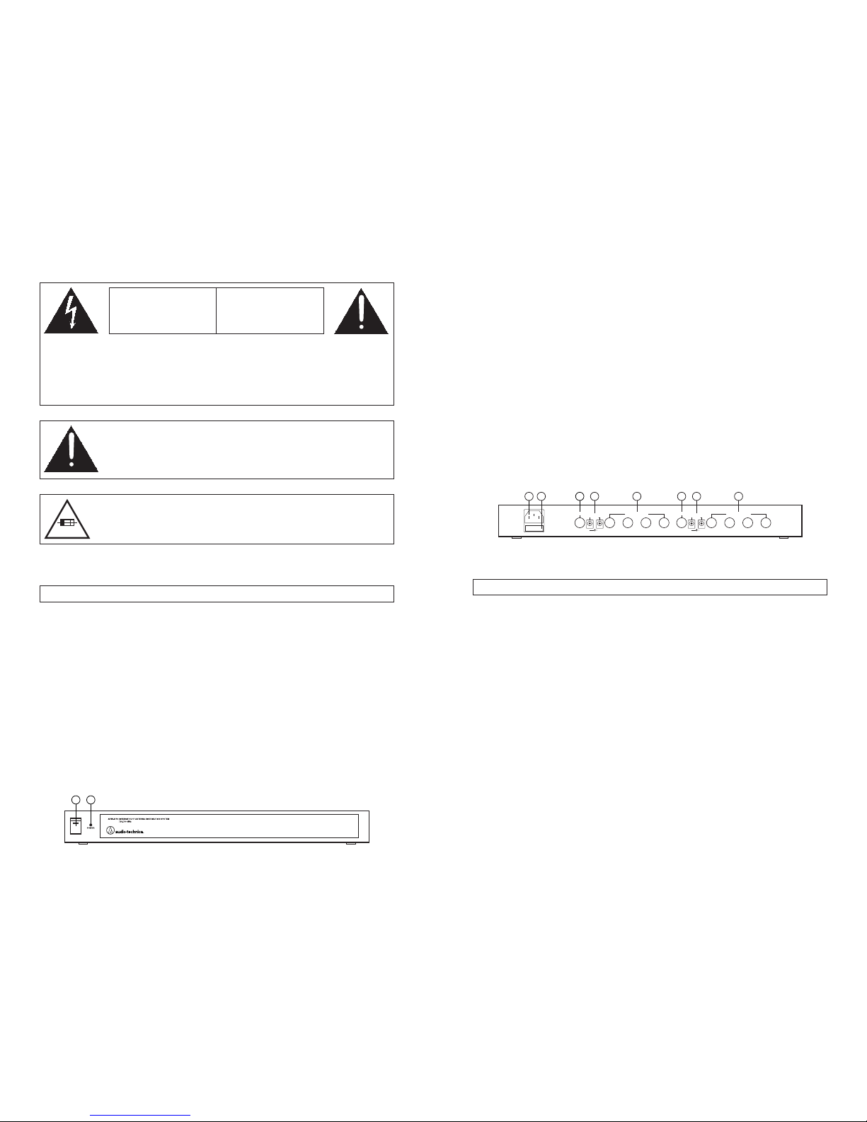
Rear Panel Controls and Functions (Fig. B)
3. AC Power Input: Attach the included AC power cord here.
4. Fuse Holder: To check or replace fuse, remove holder with a small screwdriver.
Replace fuse with 250V 2.5A fuse only.
5. Channel B Antenna Input Jack: Attach UHF antenna here. (Antenna and adapter both
included with ATW-R19 receiver.)
6. DC Output Jacks: Connect the included DC interconnect cables here to supply 12V DC
(center
positive
) to up to four ATW-R19 (or like-powered) receivers. These output jacks
also can power up to four ATW-R73 (or like-powered) receivers, when used with the
optional ATW-RDCP polarity-inverting DC interconnect cables.
7. Channel B Distribution System Output Jacks: Connect to antenna inputs on up to four
receivers with included BNC to BNC interconnect cables. Unused outputs do not require
termination.
8. Channel A Antenna Input Jack.
9. Channel A Distribution System Output Jacks.
Figure B: ATW-D70 rear view
12
+
OUTPUT
12V DC
POWER INPUT
90-260V AC
50-60 Hz
60 W
OUTPUT
12V DC
+
ANTENNA A OUTPUT
ANTENNA AANTENNA B OUTPUT
ANTENNA B
3 41 2 3 4
INPUTINPUT
2
Figure A: ATW-D70 front view
1
3
Input Impedance 50 ohms
Output Impedance 50 ohms
Useable Frequency Range
ATW-D70 728-750 MHz
ATW-D90 940-955 MHz
Nominal Amplifier Gain 0 dB, ±3 dB
Power Supply Input 90-260V AC, 50-60 Hz, 60W
DC Output 12V DC, center
positive
, 500 mA maximum per jack
Dimensions 16.93" (430.0 mm) W x 1.92" (48.8 mm) H x
7.60" (193.0 mm) D
Weight 5.7 lbs (2.6 kgs)
Accessories Included 1 power cord, 8 interconnect cables (BNC to BNC),
4 ATW-RDCN DC interconnect cables, 1 rack-mount kit
Optional Accessories ATW-RDCP: Polarity-inverting DC interconnect cables
(set of four) for use with ATW-R73 or like-powered
receivers (center
negative
DC jacks).
ATW-RA1: Rack-mount antenna kit brings antenna inputs
to the front of unit for ease of setup, or when receiver is
enclosed in a metal rack. Includes a pair of extendible
antennas suitable for UHF or VHF use.
2.5A 250V
5 6 7 8 6 9
To prevent electric shock, do not remove the cover. There are no user-serviceable parts
inside. Internal adjustments are for qualified professionals only. Refer all servicing to
qualified service personnel.
Pour prévenir un choc électrique, ne pas ouvrir le couvercle. Il n’y aucune pièces de
rechanges à l’intérieur. Tout ajustement interne doit être fait par une personne qualifié
seulement. Référez tout réparation au personnel qualifié.
Warning/Attention:
To prevent fire or shock hazard, do not expose this appliance to rain or
moisture.
Pour prévenir feu ou choc électrique, ne pas exposé l’appareil à la pluie
ou à l’humidité.
Prior to use of this product, review all safety markings and instructions.
4
 Loading...