

Page 1
ATW-CHG3N
IP Control Protocol Specifications
TWO-BAY CHARGING STATION
Version1.0.1
Page 2

Revision history
Date Version Description of change
2018/11/05 1.0.1 First version
Page 3
Table of Contents
1 Preface ........................................................................................................................................................ 1
1.1 Purpose of This Document ....................................................................................................................... 1
1.2 Definition of Terms and Numeric Representation ..................................................................................... 1
2 Basic Specifications ..................................................................................................................................... 2
2.1 Communication Interfaces ....................................................................................................................... 2
2.2 Command Formats .................................................................................................................................. 2
2.2.1 Command Common Rules ................................................................................................................ 2
2.2.2 Set Command/Get Command/Request Command ........................................................................... 3
2.2.3 ACK .................................................................................................................................................. 3
2.2.4 NAK .................................................................................................................................................. 4
2.2.5 Answer .............................................................................................................................................. 4
2.2.6 Information ........................................................................................................................................ 5
3 Command List .............................................................................................................................................. 6
4 TCP Communications .................................................................................................................................. 7
4.1 Communication Control .........................................................................................................
4.1.1 Communication Start ........................................................................................................................ 8
4.1.2 Control Sequence ............................................................................................................................. 8
................... 7
4.1.3 Communication Errors .................................................................................................................... 11
4.1.4 Communication End ........................................................................................................................ 11
4.2 Command Details ................................................................................................................................... 12
......................................................................... 13
......................................................................................... 13
................................................................................. 14
............................................................................. 15
.......................................................................................................... 16
..................................................................................................... 16
................................................................................................. 17
............................................................................................. 18
........................................................................................ 18
............................................................................................................... 19
............................................................................................... 20
.................................................................................. 20
.............................................................................................................................. 20
5 UDP Communications ............................................................................................................................... 21
5.1 Communication Control .......................................................................................................................... 21
5.1.1 Communication Start ...................................................................................................................... 21
5.1.2 Control Sequence ........................................................................................................................... 21
5.1.3 Communication Errors .................................................................................................................... 21
5.1.4 Communication End ........................................................................................................................ 21
5.2 Command Details ................................................................................................................................... 22
.............................................................................................................. 22
Page 4

1 Preface
This document describes the command specifications to control the Wireless System charger developed in
Audio-Technica.
The following table shows the definition of terms used in this document.
Ter m Description
Host A device that issues control commands. It refers to application software or a
control device.
Device A device to be controlled.
AT device An Audio-Technica product device.
Message A character string transmitted per communication in data format.
Command A command statement to control a device. It is included in a message.
Parameter Used in combination with a command. It is a setting value that specifies a
command behavior.
The numeric representation is defined as follows:
Binary number: Specify a value followed by b. Example: 1010 0110b
Hexadecimal number: Specify a value preceded by 0x. Example: 0xA6
1
Page 5
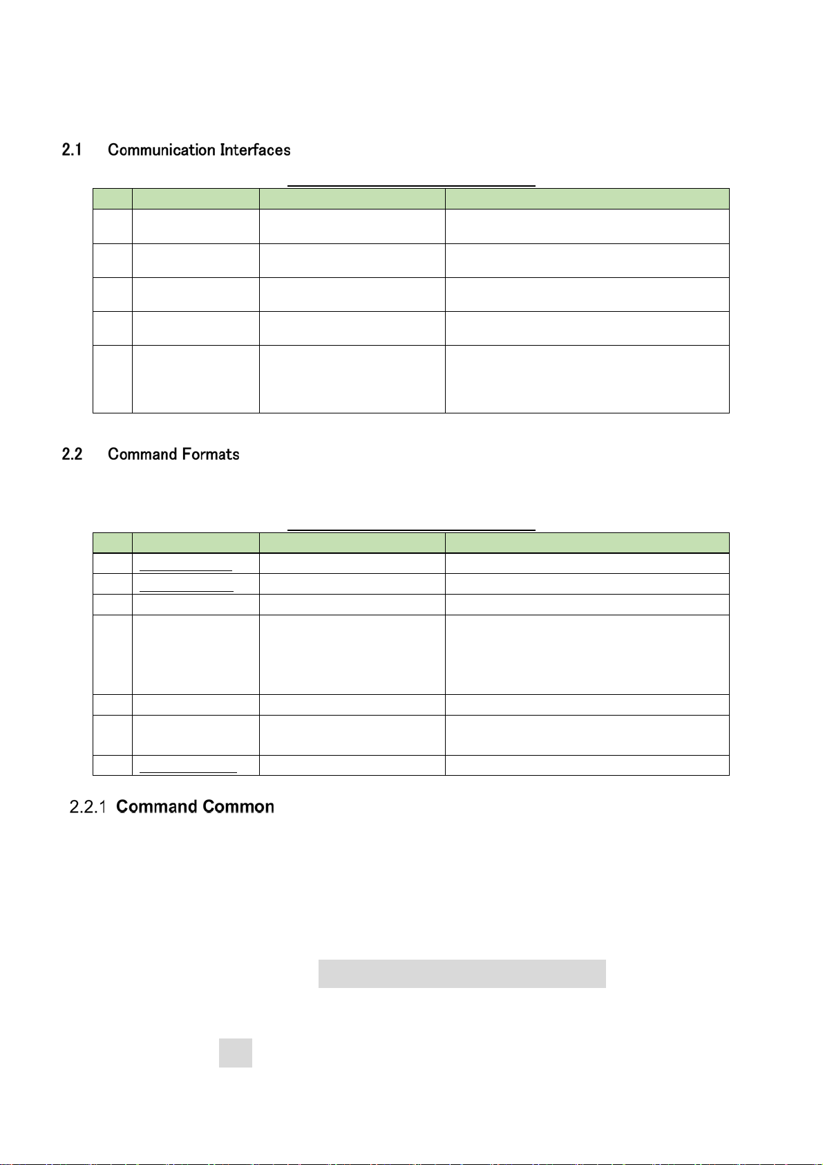
2 Basic Specifications
The update function updates the Wireless System via TCP protocol.
Table 2-1 Communication Interfaces
No Item Content Remarks
1. Communication
system
2. Transmission
speed
3. Port number
4. Maximum data
length
5. Compatible
connector
Full duplex
10Mbps / 100Mbps
TCP (control): 17300
UDP (notification): 17000
287 bytes (including line
feed codes)
Device side: RJ45
connector (compatible
with 10/100 Mbps)
Cable: CAT5e or higher
Each port number is fixed and cannot be
changed.
32 bytes for Ethernet communication
header, 255 bytes for control commands
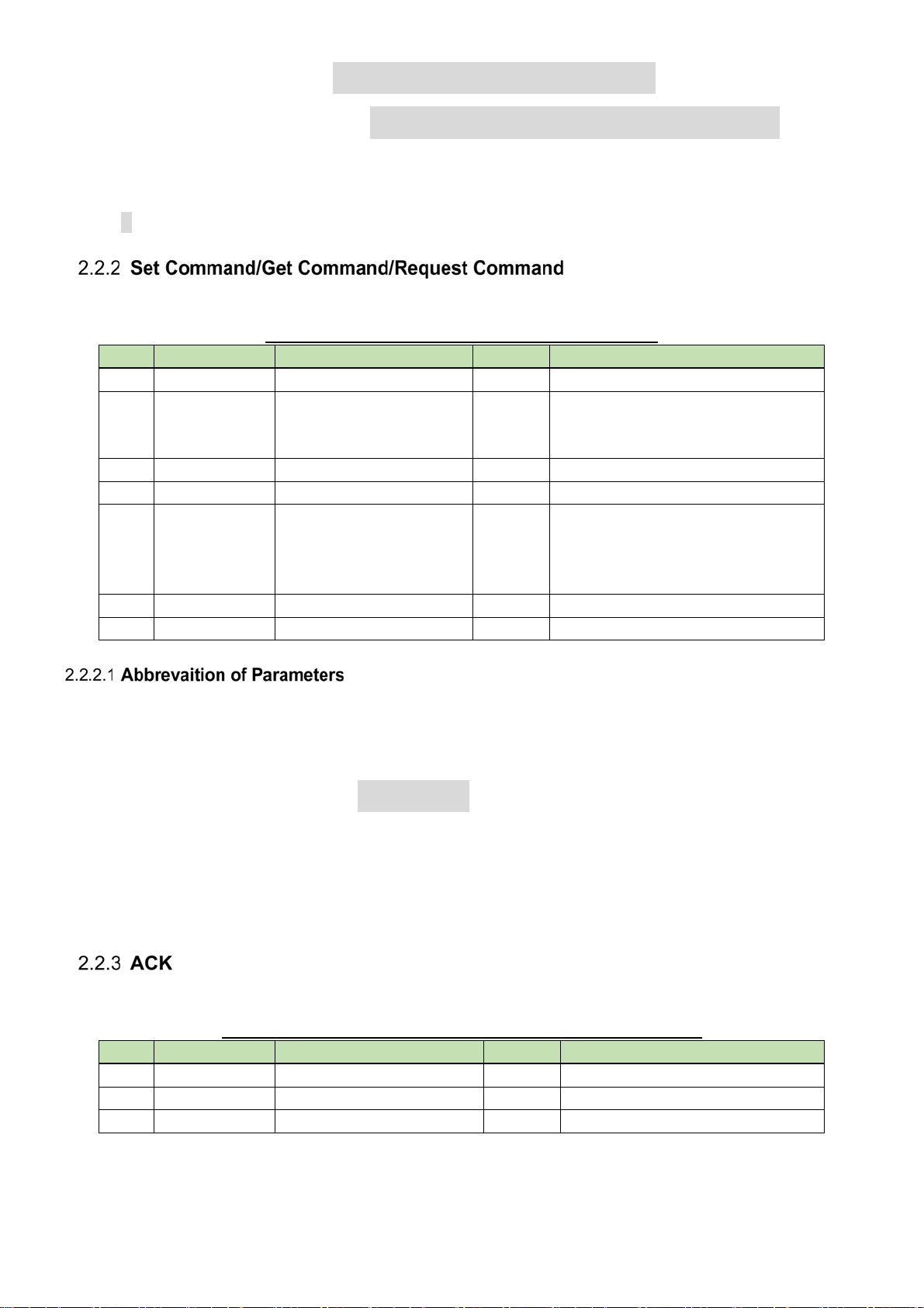
Transmitted commands are categorized as follows:
Table 2-2 Communication Interfaces
No Command Content Remarks
1. Set Command Action command Change the charger settings.
2. Get Command Action command Obtain the charger settings and status.
3. ACK Acknowledge Respond to a Set Command.
4.
NAK
5. Answer Setting change notification Respond to a Get Command.
6. Information Status change notification Report the charger settings and status
7. Req Command Action request Request an action to the host.
Negative acknowledge Respond to a Set Command.
① For delimiter, half-width space (␣:0x20) will be used.
② Commands use basically ASCII code. For specific commands UTF-8 is used (Example: Device naming
etc.)
③ The termination of a command is CR(0x0d).
[Example].
change (not used for update).
sprchS000000NC1,,1,,,1,471250000,01,01,0 ↲
sprchACK↲
sprchNAK01↲
2
Page 6
gprch000000NC2,,0,,,1,580925000,03,12,1 ↲
MDnprch000000NC1,0,0,11,0,1234,0,808750000,0,0 ↲
・・・ means space
↲・・・ means CR(0x0d)
・・・ means command parameter
The table below shows command protocol of the action commands.
Table 2-3 Command protocol of action commands
No. Item Content Size Remarks
1. Command Command string 5byte Refer to “3.Table of commands”
2. Handshake
Select
3. Model ID Unused 4byte Fixed 0000
4. Unit No Unused 2byte Fixed 00
5. Continue
Select
6. Parameter Command parameter 0byte~ Refer to chapter 4
7. End Character Sign for end of message 1byte CR (0x0D)
When a command is sent by the host, the following parameters can be abbreviated. This is done by using
comma (,) punctuation for unspecified data.
Example. When a whole abbreviation of the parameter
Sequence execution
system
Divided message system 2byte NC: No divided message
1byte H: Handshake method (Unused)
O: One-Way method
S: ACK/NAK format
CS: Head of divided message
CM: Divided message
CE: End of divided message
sprchS000000NC,,,,,,,,, ↲
However, depending on the command
“Error” can occur when a whole abbreviation of the parameter
“Unspecified” can occur when no abbreviation of the parameter
Cases above and parameters which cannot be abbreviated are described by each command from chapter
4.2 on.
Below, is the acknowledgment command format.
Table 2-4 Response to the acknowledgment command format
No Item Content size Remarks
1. Command Command string 5byte Refer to “3.Table of commands”
2. ACK ACK 3byte Fixed ACK
3. End Character Sign for end of message 1byte CR (0x0D)
3
Page 7
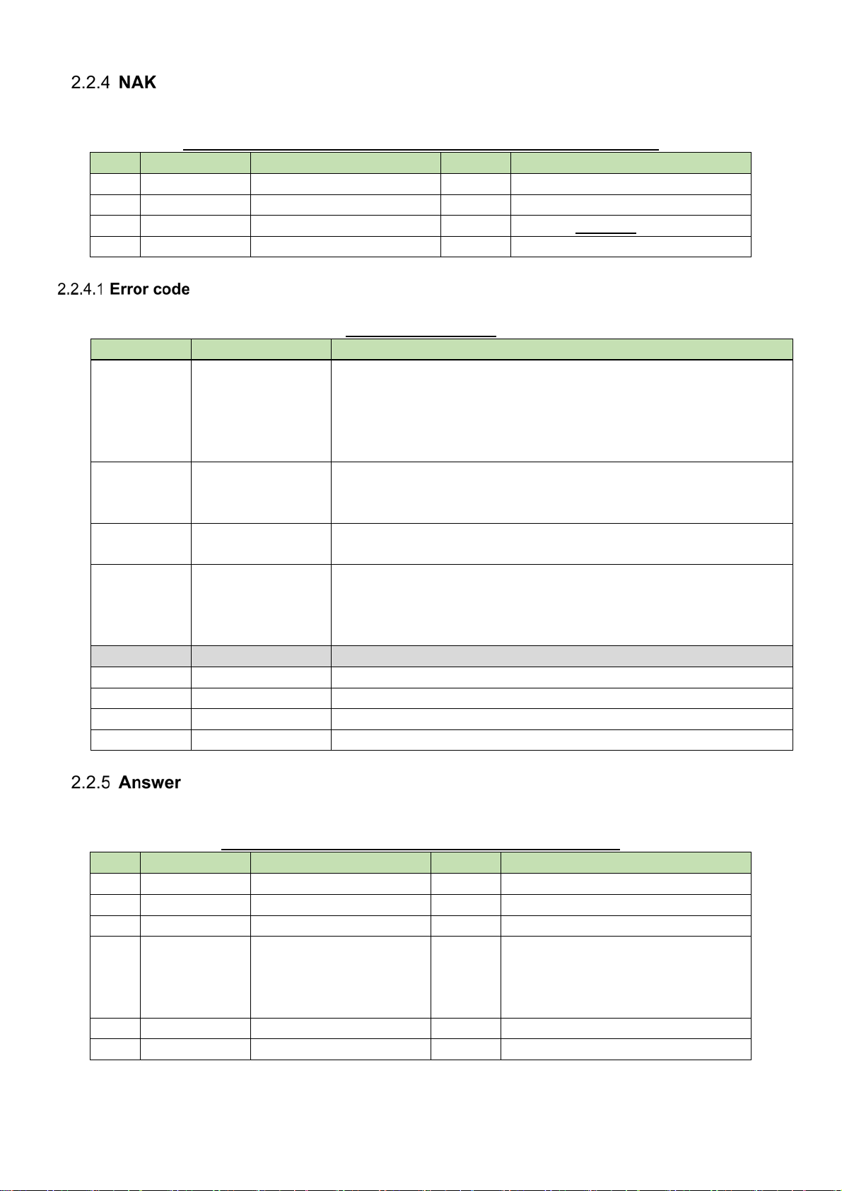
Below, is the negative acknowledgment command format.
Table 2-5 Response to negative acknowledgment command format
No Item Content size Remarks
1. Command Command string 5byte Refer to “3.Table of commands”
2. NAK NAK 3byte Fixed NAK
3. Error Code Error code 2byte Refer to Table 2-6
4. End Character Sign for end of message 1byte CR (0x0D)
Below, are the error codes.
Table 2-6 Error Code
Error code Error content Remarks
01 Grammar error
02 Invalid command
03 Divided
Transmission Error
04 Parameter error
05 Transmit timeout Unused
90 Busy Unable to process due to busy state
92 Busy (Safe Mode) Unable to process due to p-Fail (power interruption)
93 Busy (Extension) Unable to process due to Extension mode (CU link)
99 Other errors Other errors than above
・ No mandatory request
・ Failure in mandatory request command string
・ Defined length of a command string is not appropriate
・ Max. length of command string including line feed code is
exceeded
・ Cannot find command
(Refers to an unknown command or a command, which the device
cannot use.)
・ Referred to “CM” or “CE” in a state, when “CS” Continue Select
is not received.
・ Refers to an invalid RX
・ Parameter is out of the defined range
・ When trying to change a parameter, which cannot be changed
(i.e. change “Priority” during talk,...)
Below, is the setting status notification.
Table 2-7 Command format of setting status notification
No Item Content size Remarks
1. Command Command string 5byte Refer to “3.Table of commands”
2. Model ID Unused 4byte Fixed 0000
3. Unit No Unused 2byte Fixed 00
4. Continue
Select
5. Parameter Command parameter 0byte~ Refer to chapter 4 and 5
6. End Character Sign for end of message 1byte CR (0x0D)
Divided message system 2byte NC: No divided message
CS: Head of divided message
CM: Divided message
CE: End of divided message
4
Page 8
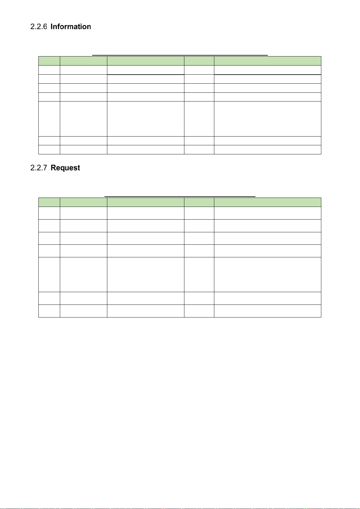
Below, is the changing status notification.
Table 2-8 Command format of changing status notification
No Item Content size Remarks
1. Modify MD 2byte Fixed MD
2. Command Command string 5byte Refer to “3.Table of commands”
3. Model ID Unused 4byte Fixed 0000
4. Unit No Unused 2byte Fixed 00
5. Continue
Select
6. Parameter Command parameter 0byte~ Refer to chapter 5
7. End Character Sign for end of message 1byte CR (0x0D)
Divided message system 2byte NC: No divided message
CS: Head of divided message
CM: Divided message
CE: End of divided message
Below, is the requesting status notification. ( This command is not used for wireless system)
Table 2-9 Command format of c status notification
No Item Content size Remarks
1.
2.
3.
4.
5.
6.
7.
Request
Command
Model ID
Unit No
Continue
Select
Parameter
End Character
RQ 2byte Fixed RQ
Command string 5byte Refer to “3.Table of commands”
Unused 4byte Fixed 0000
Unused 2byte Fixed 00
Divided message system 2byte NC: No divided message
CS: Head of divided message
CM: Divided message
CE: End of divided message
Command parameter 0byte~ Refer to chapter 4
Sign for end of message 1byte CR (0x0D)
5
Page 9

3 Command List
No.
1 Model Info
2
Category
Command
gprmi
gveri
Table 2-10 Command List
Command Name
Model parameter information
acquisition request
Version information acquisition request
Remarks
Obtain the model parameter information.
Obtain the version information.
type
set get info
○
○
Ref.
3 System Setting
4
5 Network Setting
6
7
8
9 Status
10
11 Boot Mode
12 request
snmlb
gnmlb
snetw
gnetw
silog
gilog
gschg
nschg
gmode
rfrst
Name label setting change request
Name label setting acquisition request
Network setting change request
Network setting acquisition request
Log setting change request
Log setting acquisition request
Charge status acquisition request
Charge status notification
Mode acquisition request
Reset request (to factory settings)
Change the name label settings.
Obtain the name label settings.
Change the network parameter settings.
Obtain the network parameter settings.
Change the log settings.
Obtain the log settings.
Obtain the charge status.
Report a change in the charge status.
Obtain the boot mode.
Reset to the factory settings.
○
○
○
○
○
○
○
○
○
○
13
14
rdflp
rrbot
Display flip and flash request (for
identify)
Reboot request
Flip and flash the display.
Reboot the system.
6
○
○
Page 10

4 TCP Communications
To control the Wireless System charger from the host, TCP protocol is used for communications.
The graphic below illustrates the communication control flow of the IP control.
WirelessSystem
PowerON
Se tti ng m ana gement
function
Initialization
Booting
IP Contorl
Host
Wait for defining IP-Address
(IP config mode)
Generate Socket
Wait for Connection
Establish connection from Host
Wait for rece ive
Processing each command
Change of setting or state
After the system start, “Initializing” follows “Waiting for connection”
After established host connection, on “Waiting for connection” follows “Waiting for
The received command will be processed depending on the internal process task and a
If the host will be disconnected, “Waiting for transmission” changes to “Waiting for
Send command from Host
ACK/NAK or Answer
〜〜 〜
Disconne ct from Host
〜〜 〜
Send informat ion to Host (Multic ast)
Fig. 4-1 Communication Control Flow
transmission”
result (ACK/NAK) will be sent. But because this process is asynchronous, it is also possible
to receive commands during processing (without waiting for ACK/NAK or Answer, the next
command can be sent). Although based on the command, NAK(90:BUSY) can also occur.
connection”
7
Page 11

The host establishes connections with the Wireless System.
Multiple hosts cannot be connected. This is single connection.
Table 2-11 Communication Control Parameters
No Name Default Setting Remarks
1. IP Address Auto
2. Port No 17300
As “Set Command” response, the wireless system sends back ACK/NAK to the source.
<Example> Refer below for chage request of RX parameter setting.
WirelessSystem
Setting management
function
IP contorol
Host
Lock key input
Change
RX param eter
ACK/NAK
Unlock key input
Graph 4-2 Set Command Processing Sequence
In terms of Set Command, when errors like grammar error, parameter failure etc. occur, the command NAK
will sent to the source and run the key input unlock.
Set RX
Parameter
8
Page 12

m
As “Get Command” response, the wireless system sends back Answer to the source.
<Example> Refer below for Receive Parameter Setting Acquisition Request sequence.
WirelessSy stem
Also for Get Command, when errors like grammar error, parameter failure etc. occur, the command NAK
will sent to the source.
Setting manageme nt
function
Refe r to rec eive settin g
Answer/NC
IP control
Get RX
Parameter
Fig. 4-3 Get Command Process Sequence
Host
WirelessSyste
Setting management
funtion
Refer to RX
parameter
(unspecified)
NAK 04
Fig. 4-4 Get Command Process Sequence (NAK)
IP control
Host
Get RX Parameter
9
Page 13

The request command sends whether the command was accepted or not to the sender via ACK/NAK and
then performs the requested process if it was accepted (ACK response).
There is a subsequent command available to send the measurement result to the sender.
[1] Command involving reset
<Example> The sequence of reset request (to factory settings) is shown below.
WirelessSystem
Se tt in g m ana gem ent
function
Refer to
system status
Lock key entry
Ack/Nak
Reset
(Set to factory
settings)
IP c on trol
Request Reset
Disconnect with reset
Fig. 2-5 Request Command Process Sequence (Command Involving Reset)
* For NAK responses (telegraphic error, system busy status, etc.), the system is not reset.
Key entry is also unlocked.
Host
10
Page 14

Refer below, in case of ACK/NAK transmitting error sequence.
Wire lessSystem
Host
Change RX parameter
ACK/NAK
IP contorol
Set RX Param eter
Sendinng error
×
Timeout
Disconnect from Host
Fig. 2-6 Transmitting Error Sequence
Refer below, in case of ACK/NAK receiving error sequence.
Wire lessSystem
Setting ma nagement
function
IP control
Host
Indicate
"error"
Receive error
×
Set RXPara m eter
Disconnect
Fig. 2-7 Receiving Error Sequence
Devided Message is not used for IP control.
The host can disconnect at a random timing while ending the communication.
When a disconnection occurs, the Wireless System clears the status of the applied connection (eg. While
sending a file, etc.) and transitions to “Waiting for connection”. Further, the same process applies also
in case of a disconnected cable etc.
In case of a repeated communication, the host establishes a connection.
11
Disconnect
Indicate
"error"
Page 15

The following example represents the correspondence between a command to send and the command format table.
See the table and change the value to desired one in each parameter.
[Example] snetwS000000NC1,192.168.0.30,255.255.255.0,192.168.0.1,0,1,1,0,225.0.0.100,17000,1,172.16.13.15,8000,+1300,1,07010000,09302330,101
No item Description type v alue value Des cription
1 Command Command string s tring wlfts
2 Hands hake Select Sequence execution method s tring S
3 Model ID Not used s tring 0000 Not used
4 Unit No Not used s tring 00 Not used
5 Continue Select Message split method str ing NC No split
IP address acquisition method: Static
IP address: 192.168.0.30
Subnet mask: 255.255.255.0
Gateway: 192.168.0.1
Automatic device detection setting: Off
Notification enable: On
Notification by charge rate change: On
Notification by charge time change: Off
Multicast address: 225.0.0.100
Multicast port number: 17000
NTP enable: On
NTP server address: 172.16.13.15
NTP server port number: 8000
Timezone (time difference from UTC): +1300
DST enable: On
Start time: 7/1 00:00
End time: 9/30 23:30
Device ID: 101
6 Parameter Parameter
IP Setting IP settings
IP Config mode IP address acquisition method s tring 0 Auto
IP address IP address string nnn.nnn.nnn.nnn
Subnet mas k Subnet mask string nnn.nnn.nnn.nnn
Gatew ay Gateway s tring nnn.nnn.nnn.nnn
Allow Discovery
IP Control Notif ic ation IP c ontrol notification s etting
Notification Notification enable string 0 Off
Charge Rate
Charge Time
Multic ast Address Multicas t addres s string nnn.nnn.nnn.nnn
Multic ast Port No Multic ast port number str ing nnnnn 1 to 65535
NTP Serv er NTP ser v er se tt in g
NTP NTP enable string 0 Off
NTP Server A ddress NTP server address string nnn.nnn.nnn.nnn
NTP Server Port No NTP serv er port number string nnnnn
Time Zone
Daylight Saving Time Daylight saving time setting
DST DST enable string 0 Off
St ar t Dat eTi me S ta rt time s tr ing MMDDHHmm
End Dat eTime En d time s tr ing MMDDHHmm
Device ID Device ID string nnn 0 to 255
7 End Character Message end charac ter binary
Automatic device detecti on setting
Notification by char ge rate
change
Notification by char ge time
change
Timezone ( time dif ference
from UTC)
string 0 Off
string 0 Off
string 0 Off
s tr ing +HHmm
1Static
1On
1On
1On
1On
1On
1-digit sign (+/-) +
hour/minute string
(HHmm)
1On
↲
CR(0x 0d)
↲
12
Page 16

The charger that received the model parameter information acquisition request sends the model parameter information to the host via Answer.
[1] Get Command
The command format of the model parameter information acquisition request is shown below.
[Example] gprmiO000000NC↲
Table 2-12 Command Format
No item Description type value value Descr iption remarks
1 Command Command s tring string gpr mi
2 Handshake Select Sequence execution method string O
3 Model ID Not used s tring 0000 Not used
4 Unit No Not used s tring 00 Not us ed
5 Continue Selec t Mes sage s plit method string NC No s plit
6 Parameter Parameter - No parameter
7 End Charac ter Message end c haracter binary
↲
CR(0x 0d)
[2] Answer
The Answer command format from the charger is shown below.
[Example] gprmi000000NC"ATW-CHG3N ",5," " ↲
Table 2-13 Answer Command Format
No item Description type value value Description remarks
1 Command Command string string gveri
2 Model ID Not used str ing 0000 Not used
3 Unit No Not used str ing 00 Not us ed
4 Continue Select Message split method string NC No split
5 Parameter Parameter
Model Name Model name char "
string ATW-CHG3N 12 single-byte characters
char "
If this item contains less than 16
character s, a s ingle-byte blank
space is set at the end.
The charger that received the version information acquisition request sends the version information to the host via Answer.
[1] Get Command
No item Description type value value Descr iption remarks
[2] Answer
Rec eiv e CH Num
Destination Code Destination c ode char "
6 End Character Mess age end char acter binary
Max imu m n umbe r of
connections
string nn
string " " 6 single-byte charac ters
char "
↲
2-digit decimal number
1~
CR(0x 0d )
The command format of the version information acquisition request is shown below.
[Example] gveriO000000NC↲
Table 2-14 Command Format
1 Command Command s tring string gv eri
2 Handshake Select Sequence execution method string O
3 Model ID Not used s tring 0000 Not used
4 Unit No Not used s tring 00 Not used
5 Continue Selec t Mes sage s plit method string NC No s plit
6 Parameter Parameter - No parameter
7 End Charac ter Message end c haracter binary
The command format of Answer from the Wireless System is shown below.
↲
CR(0x 0d)
Inc luding parent charger
If this item contains less than 6
character s, a s ingle-byte blank
space is set at the end.
[Example] gveri000000NC"001.002.000 ","001.000.000 ",2,1,"001.000.001 ",2,"000.000.012 " ↲
13
Page 17

Table 2-15 Answer Command Format
No item Description type value value Description remarks
1 Command Command string string gveri
2 Model ID Not used string 0000 Not used
3 Unit No Not used string 00 Not us ed
4 Continue Select Message split method string NC No split
5 Parameter Parameter
ZIP File V ers ion char "
ZIP integrated f ile version
Main Mc u V er s ion
Main MCU F/W v er s ion
Charger Map Charger map
Charger Num Number of chargers s tring nn 1 or above
Cha r g er Data
Charger No. Charger number s tring nn 2-digit decimal number
Sub Mcu Vers ion
6 End Character Mes sage end c harac ter binary
Charger detailed infor mation (The follow ing information is repeated as many times as the number of self and connected c hargers)
Sub MCU F/W version (PIC)
string nnn.nnn.nnn 12 single-by te characters
char "
char "
string nnn.nnn.nnn 12 single-by te characters
char "
char "
string nnn.nnn.nnn 12 single-by te characters
char "
↲
CR( 0x 0d)
The version of the ZIP file name w hen
w ritten w ith the updater is stored.
If this item contains less than 12
charac ters, a single-byte blank space is
set at the end.
* MCU for parent charger only
Number of chargers including parent charger
1: Parent c harger
2 or abov e: C hild charger (depending on the DI P
SW set ting)
If this item contains less than 12
charac ters, a single-byte blank space is
set at the end.
The charger that received the network parameter setting change request sends the processing result to the host via ACK or NAK.
To apply the change, a reboot is required. This command does not automatically reboot the system.
[1] Set Command
The command format of the network parameter setting change request from the host is shown below.
[Example] snetwS000000NC1,192.168.0.30,255.255.255.0,192.168.0.1,0,1,1,0,225.0.0.100,17000,1,172.16.13.15,8000,+13:00,1,07010000,09302330,101↲
Table 2-16 Command Format
No item Description ty pe value v alue Description remarks
1 Command Command string string snetw
2 Handshake Select Sequence ex ecution method string S
3 Model ID Not us ed str ing 0000 Not used
4 Unit No Not us ed string 00 Not used
5 Continue Selec t Message split method s tring NC No split
6 Parameter Parameter
IP Setting IP settings
IP Conf ig mode IP address acquisition method string 0 Auto
1Static
IP address IP address string nnn.nnn.nnn.nnn Requir ed w hen Static is selected
Subnet mas k Subnet mask string nnn.nnn.nnn.nnn Requir ed w hen Static is selected
Gatew ay Gatew ay string nnn.nnn.nnn.nnn
Allow Discovery
IP Control Notification IP control notification setting
Notif ication Notification enable string 0 Off
Charge Rate
Charge Time
Multicas t Addr ess Multicast addres s string nnn.nnn.nnn.nnn
Multicas t Port No Multic ast port number string n to nnnnn 1 to 65535
NTP Server NTP ser ver s et t ing
NTP NTP enable string 0 Off
NTP Server A ddress NTP server address string nnn.nnn.nnn.nnn
NTP Server Port No NTP serv er port number string n to nnnnn
Automatic devi ce detec tion setting
Noti fic ation by charg e rate c hange
Noti fic ation by charg e time ch ange
string 0 Off
1On
1On
string 0 Off
1On
string 0 Off
1On
1On
Time Z on e
Daylight Saving Time Daylight saving time setting
DST DST enable string 0 Off
Start DateTime Start time string MMDDHHmm Can be set in inc rements of 1 hour
End DateTime End time string MMDDHHmm Can be set in increments of 1 hour
Device ID Device ID string nnn 0 to 255
7 End Charac ter Message end character binary
Timezone (time differ ence
from UTC)
string +HH:mm
1On
↲
14
1-digit sign (+/-) + hour/minute
string (HH:mm)
CR(0x 0d)
Can be set betw een -12:00 and +14:00 in
increments of 30 minutes
Page 18

[2] ACK/NAK
[Example] snetwACK↲
Table 2-17 Command Format
No item Description type value value Description r emarks
1 Command Command string string s prch The received c ommand is set.
2 A CK A CK s tr in g A CK
3 End Character Mes sage end character binar y
↲
CR(0x 0d)
[Example] snetwNAK01 ↲
Table 2-18 Command Format
No item Des cription type value value Des cription remarks
1 Command Command string str ing sprch The received command is s et.
2 NAK NAK string NAK
3 Error Code Error c ode string 00 to 99 Er ror c ode Ref er to Chapter 2.2.4.
4 End Character Message end charac ter binary
↲
CR(0x 0d)
The charger that received the network parameter setting acquisition request sends the network parameter settings to the host via Answer.
[1] Get Command
The command format of the network parameter setting acquisition request from the host is shown below.
[Example] gnetwO000000NC↲
No item Description type value value Descr iption remarks
1 Command Command s tring string gnetw
2 Handshake Select Sequence execution method string O
3 Model ID Not used s tring 0000 Not used
4 Unit No Not used s tring 00 Not used
5 Continue Selec t Mes sage s plit method string NC No s plit
6 Parameter Parameter - No parameter
7 End Charac ter Message end c haracter binary
[2] Answer
The Answer command format from the charger is shown below.
[Example] gnetw000000NC1,192.168.0.30,255.255.255.0,192.168.0.1,00-0A-45-12-34-56,0,1,1,0,225.0.0.100,17000,
1,172.16.13.15,8000,+1300,1,07010000,09302330,101 ↲
Table 2-19 Command Format
↲
CR(0x 0d)
15
Page 19

Table 2-20 Answer Command Format
No item Description type value value Description remarks
1 Command Command string string gnetw
2 Model ID Not used string 0000 Not used
3 Unit No Not used string 00 Not used
4 Continue Select Message split method string NC No split
5 Parameter Parameter
IP Setting IP settings
IP Conf ig mode IP address ac quisition method string 0 Auto
1 Static
IP address IP address string nnn.nnn.nnn.nnn
Subnet mas k Subnet mask s tring nnn.nnn.nnn.nnn
Gatew ay Gatew ay string nnn.nnn.nnn.nnn
MAC Address MAC address string xx-xx-xx-xx-xx-xx
Allow Discovery Automatic detection setting string 0 Off
1On
IP Contr ol Notif ication IP control notification setting
Notif ication Notification enable string 0 Of f
1On
Charge Rate
Charge Time
Multicas t Address Multicast address string nnn.nnn.nnn.nnn
Multicas t Por t No Multicast port number string nnnnn 1 to 65535
NTP Server NTP se r v er s et ting
NTP NTP enable s tring 0 Off
NTP Server A ddress NTP server address string nnn.nnn.nnn.nnn
NTP Server Port No NTP ser ver port number string n to nnnnn
Time Zone
Daylight Saving Time Daylight saving time setting
DST DST enable string 0 Off
St a r t Da teTime S t art ti me s tr ing MMDDHHmm
End Da t eTime End t ime s tr ing MMDDHHmm
Device ID Device ID string nnn 0 to 255
6 End Character Message end charac ter binary
Notif ication by charge rate
change
Notif ication by charge time
change
Timezone (time difference
from UTC)
string 0 Of f
1On
string 0 Of f
1On
1On
string +HHmm
1On
↲
1-digit sign (+/-) +
hour/minute s tring (HHmm)
CR( 0x 0d)
The charger that received the log setting change request sends the processing result to the host via ACK or NAK.
[1] Set Command
The command format of the log setting change request from the host is shown below.
[Example] silogS000000NC0↲
No item Description type value value Description remarks
1 Command Command string string silog
2 Handshake Select Sequence ex ecution method string S
3 Model ID Not used string 0000 Not used
4 Unit No Not used string 00 Not used
5 Continue Selec t Mes sage s plit method s tring NC No split
6 Parameter Parameter
Enable Log settings string 0 Off
7 End Charac ter Message end char acter binary
[2] ACK/NAK
Refer to [2] in Network Parameter Setting Change Request.
The charger that received the log setting acquisition request sends the log settings to the host via Answer.
[1] Get Command
The command format of the log setting acquisition request from the host is shown below.
[Example] gilogO000000NC↲
Table 2-21 Command Format
1On
↲
CR(0x 0d)
Req uir ed
16
Page 20

Table 2-22 Command Format
No item Description type value value Descr iption remarks
1 Command Command s tring string gilog
2 Handshake Select Sequence execution method string O
3 Model ID Not used s tring 0000 Not used
4 Unit No Not used s tring 00 Not used
5 Continue Selec t Mes sage s plit method string NC No s plit
6 Parameter Parameter - No parameter
7 End Charac ter Message end c haracter binary
↲
CR(0x 0d)
[2] Answer
The Answer command format from the charger is shown below.
[Example] gilog000000NC0↲
Table 2-23 Answer Command Format
No item Description type value value Description remarks
1 Command Command string string gilog
2 Model ID Not used string 0000 Not used
3 Unit No Not used string 00 Not us ed
4 Continue Select Mes sage s plit method s tring NC No split
5 Parameter Parameter
Enable Log settings string 0 Off
1On
6 End Charac ter Message end character binary
↲
CR(0x0d)
The charger that received the receive parameter setting acquisition request sends the receive parameter settings to the host via Answer.
[1] Get Command
The command format of the receive parameter setting acquisition request from the host is shown below.
[Example] Child charger 1 port 2 gschgO000000NC2,2 ↲
[Example] Parent charger all ports gschgO000000NC1,0 ↲
[Example] All chargers all ports gschgO000000NC0,0 ↲
[Example] Child charger 2 port 1 gschgO000000NC3,1 ↲
Table 2-24 Command Format
No item Description type value value Description remarks
1 Command Command string string gsc hg
2 Handshake Select Sequence ex ecution method string O
3 Model ID Not used string 0000 Not used
4 Unit No Not used string 00 Not us ed
5 Continue Select Mes sage s plit method string NC No split
6 Parameter Parameter
0: All connec ted chargers
1: Parent charger
2 or above: Connected child charger ID
0: All char ger ports
1 or above:
CHG3 has 2 charging ports , and the one w ith
the pow er LED is port 1.
* The charging port can be specified only
w hen the charger number is set to other than
0.
Charger Num Charger number to obtain string nn
Port Number
Charging port number to
obtain
string n
2-digit decimal number
0~
1-digit decimal number
0~
7 End Charac ter Mes sage end c haracter binary
[2] Answer
The Answer command format from the charger is shown below.
[Example] Child charger 1 port 2 gschg000000NC1,2,2,1,0,0,0,36 ↲
[Example] Parent charger all ports gschg000000NC1,1,1,0,2,1,0,0,0,0,0,2,1,0,0,0,18 ↲
[Example] All chargers all ports gschg000000NC4,1,1,0,2,1,0,0,0,0,0,2,1,0,0,0,18,2,1,0,2,1,1,0,0,0,102,2,1,0,0,0,36,
4,1,0,2,1,1,0,1,0,93,2,0,0,0,0,0,5,1,0,2,1,1,0,0,0,99,2,1,0,1,0,150 ↲
[Example] Child charger 2 port 1 gschg000000NC1,3,0,0,0 ↲
* The status of each charger shown in the examples above is as follows:
Parent charger Connected/Port 1: Microphone not installed/Port 2: Microphone installed, Charging, 18 minutes
Child charger 1 Connected/Port 1: Microphone installed, Charging, 102 minutes/Port 2: Microphone installed, Charging,
36 minutes
Child charger 2 Not connected/Port 1: None/Port 2: None
Child charger 3 Connected/Port 1: Microphone installed, Charged, 93 minutes/Port 2: Microphone not installed
Child charger 4 Connected/Port 1: Microphone installed, Charging, 99 minutes/Port 2: Microphone installed, Charged,
150 minutes
↲
CR(0x 0d)
17
Page 21

Table 2-25 Answer Command Format
No item Desc ription type value value Description remarks
1 Command Command string string gsc hg
2 Model ID Not used str ing 0000 Not used
3 Unit No Not used str ing 00 Not used
4 Continue Selec t Message split method str ing NC No s plit
5 Parameter Parameter
Charger Map Charger map
Charger Num Number of chargers s tring nn
2-digit decimal number
1~
Number of chargers to report
Charger Data
Charger No. Charger number string nn
Charger Status string 0 Not connected
Er Status string 0 None
Port Num Number of charging ports string n
Por t Da t a
Port Number Charging port number string n
Port Status Charging port status
Charger detailed inf ormation (The f ollow ing information is repeated as many times as the number of self and connected chargers )
Charger status
1 Connected
Error s tatus The error type can be added in the future.
Each charging port detailed information (The following information is repeated as many times as the number of channel data or l ess.) CHG3no
string 0 Microphone not installed
1 Communication error
1 Microphone installed
2-digit decimal number
1~
1-digit decimal number
0/1
1-digit decimal number
1~
1: Parent charger
2 or above: Connected child charger ID in
ascending order
If not connected, ignore the follow ing
parameters.
Number of char ging ports f or the charger to
report
If not connec ted, this is s et to 0, omitting Port
Data for the target charger .
CHG3 has 2 char ging ports, and the one w ith
the pow er LED is port 1.
If mic rophone is not installed, ignor e the
parameters other than the error status .
Err Status string 0 None
Charge Status string 0 Charging
Charge Rate Charge rate s tring nnn 3-digit decimal number
Charge Time Charge time string nnn 3-digit decimal number Up to 765 minutes in inc rements of 3 minutes
6 End Charac ter Mes sage end c haracter binary
Error s tatus The error type can be added in the future.
Charge status
1 Charge error
1 Charged
↲
CR(0x 0d)
For future use
For Li-Ion, the charge rate is sent w ith 0 to
100% or a gradation value (0: 0 to 20%/1: 21 to
40%/2: 21 to 40%, etc.).
The charger that received the name label setting change request sends the processing result to the host via ACK or NAK.
[1] Set Command
The command format of the name label setting change request from the host is shown below.
[Example] snmlbS000000NC"CHG CLASSROOM001" ↲
Table 2-26 Command Format
No item Desc ription type value value Description remarks
1 Command Command string string snmlb
2 Handshake Select Sequence exec ution method string S
3 Model ID Not used string 0000 Not used
4 Unit No Not used string 00 Not used
5 Continue Selec t Message split method string NC No split
6 Parameter Parameter
Name Label Name label char "
string NameLabel-nnn 16 single-byte c haracters
char "
7 End Charac ter Message end character binary
↲
CR(0x0d)
If this item c ontains less than 16 characters ,
a single-byte blank spac e is set at the end.
[2] ACK/NAK
Refer to [2] in Network Parameter Setting Change Request.
The charger that received the name label setting acquisition request sends the name label settings to the host via Answer.
[1] Get Command
The command format of the name label setting acquisition request from the host is shown below.
[Example] gnmlbO000000NC↲
18
Page 22

Table 2-27 Command Format
No item Description type value value Description remarks
1 Command Command string string gnmlb
2 Handshake Select Sequence execution method string O
3 Model ID Not used s tring 0000 Not used
4 Unit No Not used s tring 00 Not used
5 Continue Selec t Message split method string NC No s plit
6 Parameter Parameter - No parameter
7 End Charac ter Message end c haracter binary
↲
CR(0x 0d)
[2] Answer
The command format of Answer from the Wireless System is shown below.
[Example] gnmlb000000NC"ATW-CHG3N 123456" ↲
Table 2-28 Answer Command Format
No item Description type value value Description r emar ks
1 Command Command string str ing gnmlb
2 Model ID Not used s tring 0000 Not used
3 Unit No Not used s tring 00 Not used
4 Continue Select Message split method string NC No split
5 Parameter Parameter
Name Label Name label char "
string ATW- CHG3N nnnnnn 16 single-byte characters
char "
6 End Character Message end character binar y
↲
CR(0x 0d)
The default value is set w ith model name +
single-byte s pace + low er 3 bytes of MAC
address.
The charger that received the mode acquisition request sends the boot mode to the host via Answer.
[1] Get Command
The command format of the mode acquisition request from the host is shown below.
[Example] gmodeO000000NC↲
Table 2-29 Command Format
No item Description type value value Description remarks
1 Command Command string string gmode
2 Handshake Select Sequence execution method string O
3 Model ID Not used s tring 0000 Not used
4 Unit No Not used s tring 00 Not used
5 Continue Selec t Message split method string NC No s plit
6 Parameter Parameter - No parameter
7 End Charac ter Message end c haracter binary
↲
CR(0x 0d)
[2] Answer
The Answer command format from the charger is shown below.
[Example] gmode000000NC0,"ATW-CHG3N ","001.000.000 " ↲
Table 2-30 Answer Command Format
No item Description type v alue value Description r emarks
1 Command Command string string gmode
2 Model ID Not used s tring 0000 Not used
3 Unit No Not us ed string 00 Not used
4 Continue Selec t Message s plit method string NC No split
5 Parameter Parameter
Mode Boot mode string 0 Normal mode
Model Name Model name c har "
Boot Loader Ver sion char "
Version
(Boot loader or f irmw are)
6 End Charac ter Message end charac ter binary
1 A djustment mode
2 FW update mode
3 Serv ice mode
4 TX update mode
5 Debug mode DR3120 only
string xxxxxxxxxxxxxxxx 16 single-byte characters
char "
string nnn.nnn.nnn 12 single-byte c haracters
char "
↲
19
CR(0x 0d)
The specif ication is not yet determined as of
December 2017.
When the boot loader is running, this
parameter is returned to the system.
The specif ication is not yet determined as of
December 2017.
If this item c ontains less than 16 characters ,
a single-byte blank spac e is set at the end.
If this item c ontains less than 12 characters ,
a single-byte blank spac e is set at the end.
Page 23

The Wireless System that received the reset request (to factory settings) sends the processing result to the host via ACK or NAK.
[1] Set Command
The command format of the reset request (to factory settings) from the host is shown below.
[Example] rfrstS000000NC↲
No item Description type value value Description remarks
1 Command Command string string rf rst
2 Handshake Select Sequence execution method string S
3 Model ID Not used s tring 0000 Not used
4 Unit No Not used s tring 00 Not used
5 Continue Selec t Message split method string NC No split
6 Parameter Parameter - No parameter
7 End Charac ter Message end c haracter binary
[2] ACK/NAK
Refer to [2] in Network Parameter Setting Change Request.
The system is reset after ACK is sent.
The Wireless System that received the display flip and flash request sends the processing result to the host via ACK or NAK.
[1] Set Command
The command format of the display flip and flash request from the host is shown below.
[Example] rdflpS000000NC2,1,1,3,3 ↲
No item Description ty pe value value Description r emar ks
1 Command Command string s tring rdf lp
2 Handshake Select Sequence execution method string S
3 Model ID Not us ed string 0000 Not used
4 Unit No Not us ed str ing 00 Not used
5 Continue Selec t Message split method s tring NC No split
6 Parameter Parameter
Charger Map
Charger Num Number of target c hargers s tring nn
Charger Data
Charger No. Charger number str ing nn 2-digit decimal number 1: Parent charger
OPERATION Operation s tring 0 OFF
7 End Charac ter Message end character binary
Target charger map
Target charger data (The follow ing information is repeated as many times as the number of chargers)
[2] ACK/NAK
Refer to [2] in Network Parameter Setting Change Request.
When Start is selected, the display is flipped and flipped back repeatedly at one second intervals for 10 seconds after ACK is sent.
The Wireless System that received the reboot request sends the processing result to the host via ACK or NAK.
[1] Set Command
The command format of the auto squelch start request from the host is shown below.
[Example] rrbotS000000NC↲
No item Description type value value Description remarks
1 Command Command string string rrbot
2 Handshake Select Sequence execution method string S
3 Model ID Not used s tring 0000 Not used
4 Unit No Not used s tring 00 Not used
5 Continue Selec t Message split method string NC No split
6 Parameter Parameter - No parameter
7 End Charac ter Message end c haracter binary
[2] ACK/NAK
Refer to [2] in Network Parameter Setting Change Request.
Table 2-31 Command Format
↲
Table 2-32 Command Format
1 Flash Only the pow er LED flashes .
2 Flip Spare spec ification (not currently used)
3 All flash Ev en the char ge status LED flashes.
↲
Table 2-33 Command Format
↲
CR(0x 0d)
CR(0x 0d)
CR(0x 0d)
20
Page 24

5 UDP Communications
The information (status change notification) from the charger is sent via UDP protocol.
The communication control flow is the same as in 4.1 Communication Control in the Wireless System IP Control Protocol Specification.
The host registers groups to the multicast address.
No Name Default Setting Remarks
1. IP Address 225.000.000.100 Multicast address
2. Port No 17000
If the state of the wireless system changes, the below State Change Notification will be executed.
<Example> Refer below for a RX parameter setting change notification sequence.
Table 5-1 Communication Control Parameters
Wirele ssSystem
Setting manageme nt
function
Change RX parameter setting
RX Parameter
Notice
IP control
Host
Fig. 5-1 Information Command Process Sequence
The details are the same as in 4.1.3 Communication Errors in the Wireless System IP Control Protocol Specification.
The host can unregister groups at any timing.
21
Page 25

The charge status notification sends data to each port according to the following rules when notification enable is set to 1 (On) in the network parameter
settings.
• The charger status or error status changes.
• The charging port status, error status, or charge status changes.
• The charge rate changes when notification by charge rate change is set to 1 (On) in the network parameter settings (for future use).
• The charge time changes when notification by charge time change is set to 1 (On) in the network parameter settings.
[Example] Child charger 3, port 2 MDnschg000000NC1,4,1,0,1,2,0,0,0,0,0 ↲
[Example] Child charger 4, port 2 MDnschg000000NC1,5,1,0,1, 2,1,0,1,0,150 ↲
[Example] Child charger 2 MDnschg000000NC1,3,0,0,0 ↲
* The status of each charger shown in the examples above is as follows:
Parent charger Connected/Port 1: Microphone not installed/Port 2: Microphone installed, Charging, 18 minutes
Child charger 1 Connected/Port 1: Microphone installed, Charging, 102 minutes/Port 2: Microphone installed, Charging, 36
minutes
Child charger 2 Not connected/Port 1: None/Port 2: None
Child charger 3 Connected/Port 1: Microphone installed, Charged, 93 minutes/Port 2: Microphone not installed
Child charger 4 Connected/Port 1: Microphone installed, Charging, 99 minutes/Port 2: Microphone installed, Charged, 150
minutes
Table 5-2 Command Format
No item Description ty pe value v alue Des cr iption remarks
1 Modify MD string MD
2 Command Command string string nschg
3 Model ID Not us ed string 0000 Not used
4 Unit No Not us ed string 00 Not used
5 Continue Selec t Message split method string NC No split
6 Parameter Parameter
Charger Map Charger map
Charger Num Number of chargers string nn
Charger Data
Charger No. Charger number string nn
Charger Status s tring 0 Not connected
Er Status s tring 0 None
Port Num Number of charging ports string n
Por t Da t a
Charger detailed inf ormation (The f ollow ing information is repeated as many times as the number of self and connected chargers )
Charger status
Error s tatus The error type can be added in the future.
Eac h charging port detailed information (The follow ing information is repeated as many times as the number of c hannel data or less.)
1 Connected
1 Communication error
2-digit decimal number
1~
2-digit decimal number
1~
1-digit decimal number
0/1
Number of chargers to report (fixed to 1)
1: Parent charger
2 or above: Connected child charger ID in
ascending order
If not connected, ignore the follow ing
parameters.
Number of char ging ports f or the charger to
report
If not connec ted, this is s et to 0, omitting Port
Data for the target charger .
Port Number Charging port number string n
Port Status Charging port status
Err Status string 0 None
Charge Status string 0 Charging
Charge Rate Charge rate string nnn 3-digit decimal number
Charge Time Charge time string nnn 3-digit decimal number Up to 765 minutes in increments of 3 minutes
7 End Charac ter Message end character binary
Error s tatus The error type can be added in the future.
Charge status
string 0 Microphone not installed
1-digit decimal number
1~
1 Microphone installed
1 Charge err or
1 Charged
↲
CR(0x 0d)
CHG3 has 2 char ging ports, and the one w ith
the pow er LED is port 1.
If mic rophone is not installed, ignor e the
parameters other than the error status .
For future use
For Li-Ion, the c harge rate is sent w ith 0 to
100% or a gradation value (0: 0 to 20%/1: 21 to
40%/2: 21 to 40%, etc.).
22
 Loading...