

Audio Technica ATW-A65, ATW-A75 Installation And Operation Manual
Professional UHF
Wireless Systems
ATW-A65 UHF Yagi Beam Antennas, 655-681 MHz
ATW-A75 UHF Yagi Beam Antennas, 721-747 MHz
Installation and Operation
CAUTION! For personal safety and reliable system operation,
make certain that (1) the antennas are mounted clear of any
physical contact with individuals, (2) any supporting structures
used are stable, even if moved or bumped, and (3) the antennas
are securely attached to the supporting structures.
In addition, to reduce the risk of electric shock, do not allow the
antennas or their supporting structures to come in contact with
any exposed wiring or other sources of electricity.
Introduction
ATW-A65 and ATW-A75 UHF directional beam antennas provide
enhanced signal pickup for wireless systems in their designed
frequency ranges. Supplied in pairs, these antennas are ideal for
extending the range and reliability of diversity UHF wireless systems.
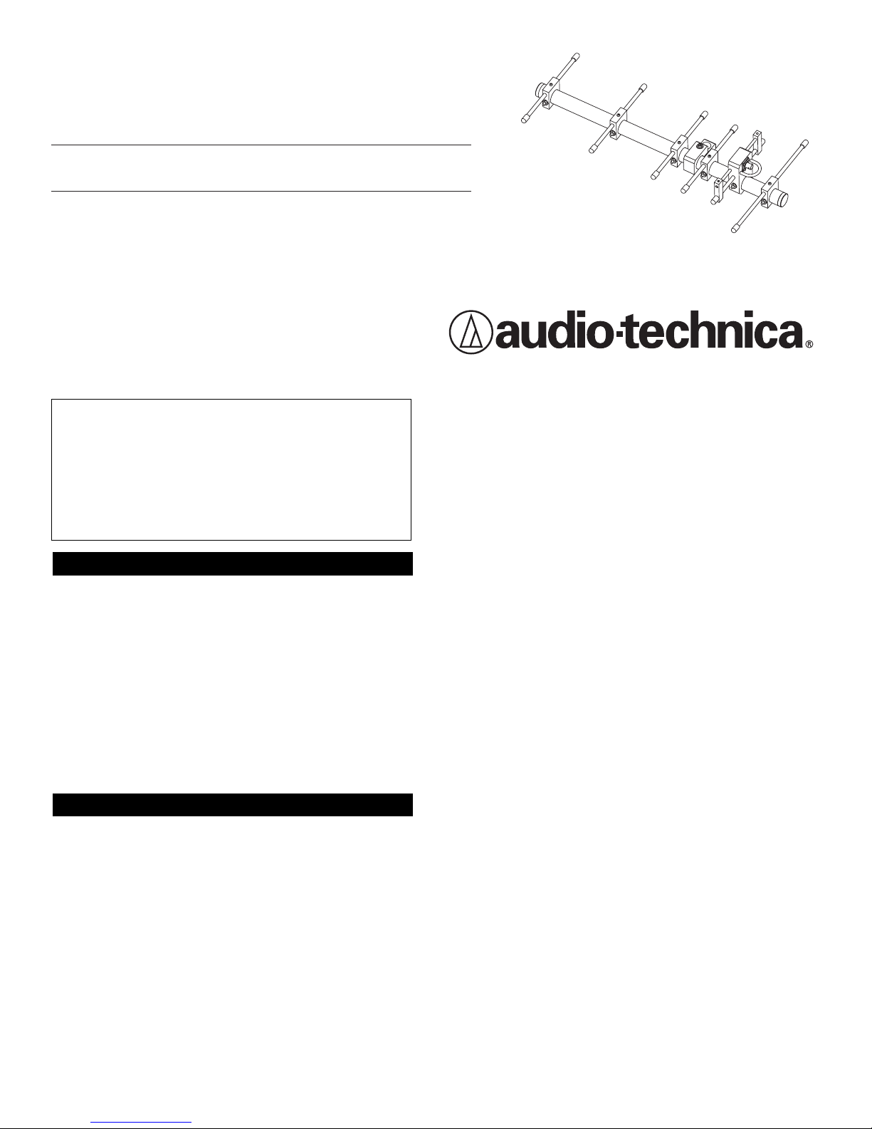
The six-element Yagi design – comprising four directors, a balanced
dipole and a reflector – provides 10 dB gain and excellent rejection of
off-axis interference. An encapsulated balun transformer efficiently
matches the “driven” dipole element to 50-ohm coax, conveniently
attached via a BNC connector.
The antennas are constructed using industrial-grade, black-anodized
aluminum rod and tubing, Delrin
®
acetyl resin mountings and stainless
steel hardware throughout, assuring long life and stable performance
under even difficult conditions. The antennas are supplied completely
assembled.
Installation
Location
For best performance, the antennas should be mounted:
• Above head-height,
• In direct line-of-sight to the likely transmitter location(s),
• At least 3' (1 m) away from each other, and
• At least 3' (1 m) away from any large metal objects or sources of
interference.
In addition, the length of RF cable run to the receiver should be
minimized. Some experimentation with antenna positioning may be
required to determine the best location under typical conditions of use.
Mounting
Near the balance-point of the boom is a Delrin mount for attachment
of the antenna. For convenience, the mount is threaded for
5
/8"-27
microphone stands and risers. Although Delrin is an extremely rugged
engineering resin,
exercise care to avoid cross-threading
when
making the threaded connection. Also, engage the 5/8"-27 thread
at
least
six full turns (about 1/4" / 6 mm
minimum
), to ensure secure
mounting in case the antenna is mechanically jarred. Use of a “jam nut”
(an additional 5/8"-27 nut on the threaded stand/riser, often supplied with
it) run up snugly against the bottom of the mount will help maintain the
desired position of the antenna.
When the screw securing the mount to the boom is loosened, the
antenna boom may be rotated in the mount, varying the effective
polarity of the antenna. Because wireless microphone transmitters
usually are in motion and/or are affected by the presence of people
and objects, the effective polarization of their RF signals typically varies
widely. Rotating the booms so the elements of one antenna are tilted
“45 degrees to the left” and the others are “45 degrees to the right”
should further enhance the performance advantages of diversity
reception. (The booms of both antennas should still be pointed toward
the target transmitter area.)
NOTE: Other than the #10 screw with wing nut that tightens the mount
on the boom,
do not adjust any hardware. Do not attempt to
change the length or position of any elements, or to tamper with
the output connector or balun. Any modification may degrade the
antenna’s performance and will void the warranty.
Connections
Once the antennas have been installed, connect them to the antenna
inputs of either a wireless receiver or an antenna distribution system.
Use RG58-type cable for cable lengths of up to 25' (8 m). For cable
lengths greater than 25', RG8-type low-loss RF cable is recommended.
RG8-type cable lengths over 100' (30 m) may cause significant signal
loss. Because cable requirements vary considerably from one installation to another, RF cables are not included. High-quality, pre-terminated
RF cables available from Audio-Technica will be found listed on the back
page under “Optional Accessories.”
AC12 RG58-type antenna cable, 12' (3.65 m) long,
terminated with BNC connectors.
AC25 RG8-type low-loss antenna cable, 25' (7.62 m) long,
terminated with BNC connectors.
AC50 RG8-type low-loss antenna cable, 50' (15.24 m) long,
terminated with BNC connectors.
AC100 RG8-type low-loss antenna cable, 100' (30.48 m) long,
terminated with BNC connectors.
Specifications
ATW-A65 ATW-A75
Frequency Range 655-681 MHz 721-747 MHz
Design Configuration Six-element Yagi Six-element Yagi
Gain (typical) 10 dBi 10 dBi
Integral Matching Device Balun transformer Balun transformer
Output Connector BNC BNC
Output Impedance (nominal) 50 ohms, unbalanced 50 ohms, unbalanced
VSWR ≤ 1.5:1 ≤ 1.5:1
Dimensions
Length 18.25" (46.4 cm) 18.25" (46.4 cm)
Width (maximum) 8.46" (21.5 cm) 8.00" (20.3 cm)
Mounting
5
/8"-27 thread
5
/8"-27 thread
Net Weight (each) 1 lb. 4 oz. (0.56 kg) 1 lb. 4 oz. (0.56 kg)
Optional Accessories
Audio-Technica U.S., Inc., 1221 Commerce Drive, Stow, Ohio 44224 330/ 686-2600 www.audio-technica.com
P51445 ©2002 Audio-Technica U.S., Inc. Printed in U.S.A.
Delrin® is a registered trademark of E.I. du Pont de Nemours and Company
One-Year Limited Warranty
Audio-Technica professional wireless systems purchased in the U.S.A. are warranted for one year from date of purchase by Audio-Technica U.S., Inc. (A.T.U.S.) to be free of defects
in materials and workmanship. In event of such defect, product will be repaired promptly without charge or, at our option, replaced with a new product of equal or superior value
if delivered to A.T.U.S. or an Authorized Service Center, prepaid, together with the sales slip or other proof of purchase date.
Prior approval from A.T.U.S. is required for return.
This warranty excludes defects due to normal wear, abuse, shipping damage, or failure to use product in accordance with the instructions. This warranty is void in the event of
unauthorized repair or modification, or removal or defacing of the product labeling.
For return approval and shipping information,
contact the Service Dept., Audio-Technica U.S., Inc., 1221 Commerce Drive, Stow, Ohio 44224.
Except to the extent precluded by applicable state law,
A.T.U.S. will have no liability for any consequential, incidental, or special damages; any warranty of merchantability
or fitness for particular purpose expires when this warranty expires.
This warranty gives you specific legal rights, and you may have other rights which vary from state to state.
Outside the U.S.A., please contact your local dealer for warranty details.
Visit our Web Site: www.audio-technica.com
 Loading...