

Page 1
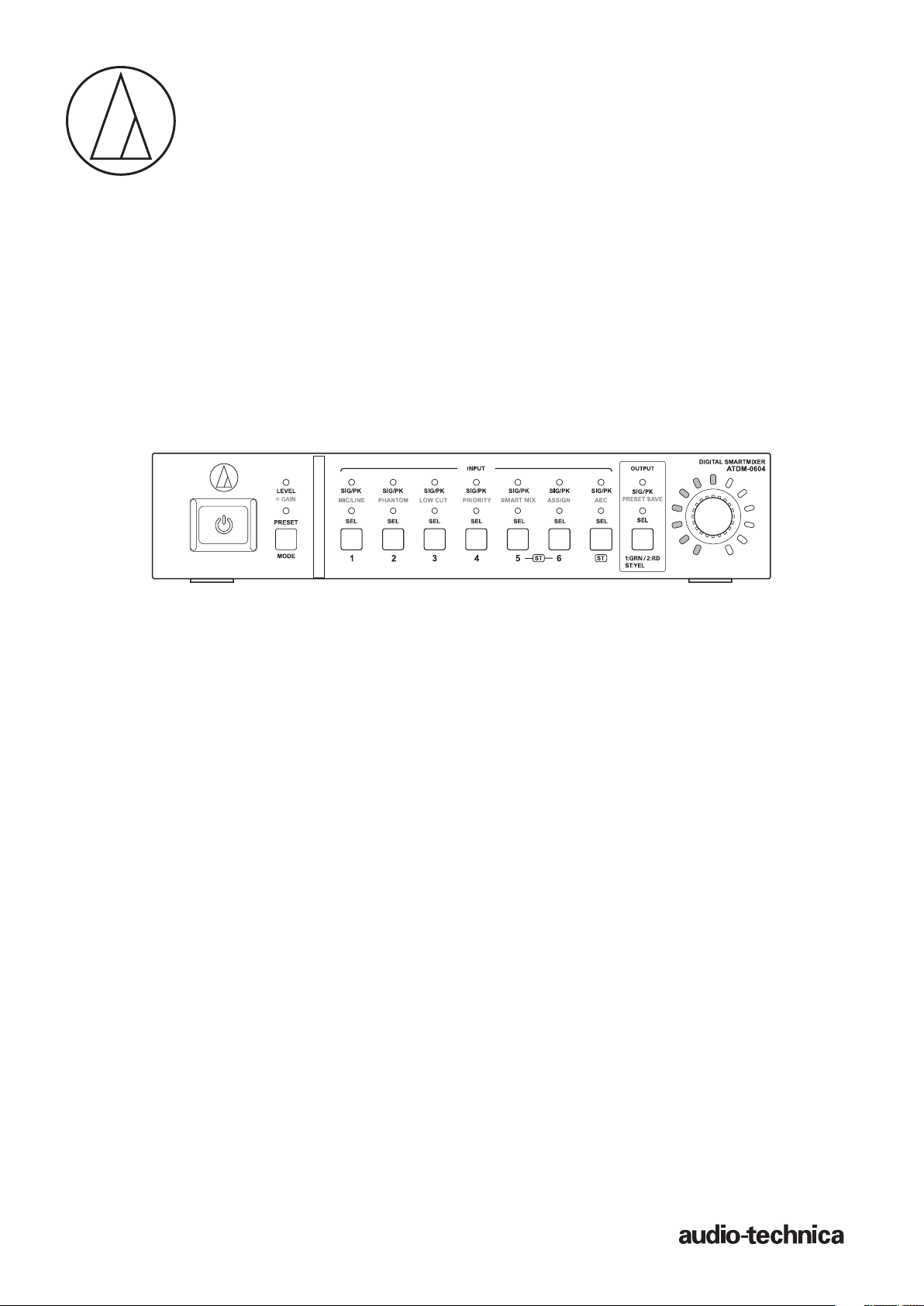
ATDM-0604
User Manual
DIGITAL SMARTMIXER
Page 2

Contents
Introduction .......................................................................................... 3
Checking the package contents .......................................................... 3
Trademarks ............................................................................................ 3
Safety precautions ............................................................................... 4
Important information ...................................................................................... 4
For customers in the USA/Canada .................................................................. 4
Important safety instructions ........................................................................... 4
FCC notice .......................................................................................................... 5
For customers in Canada ................................................................................. 5
Notes on use ......................................................................................... 6
About the product ............................................................................................. 6
Maintenance ......................................................................................... 6
Features ................................................................................................. 7
Features of ATDM-0604 .................................................................................... 7
About Audio-Technica LINK ............................................................................. 7
System installation .............................................................................. 7
Installing on a rack ............................................................................................ 7
Unbalanced connection .................................................................................... 9
Power cable connection ................................................................................... 9
How to connect a Euroblock connector .......................................................... 9
System connection examples ........................................................... 10
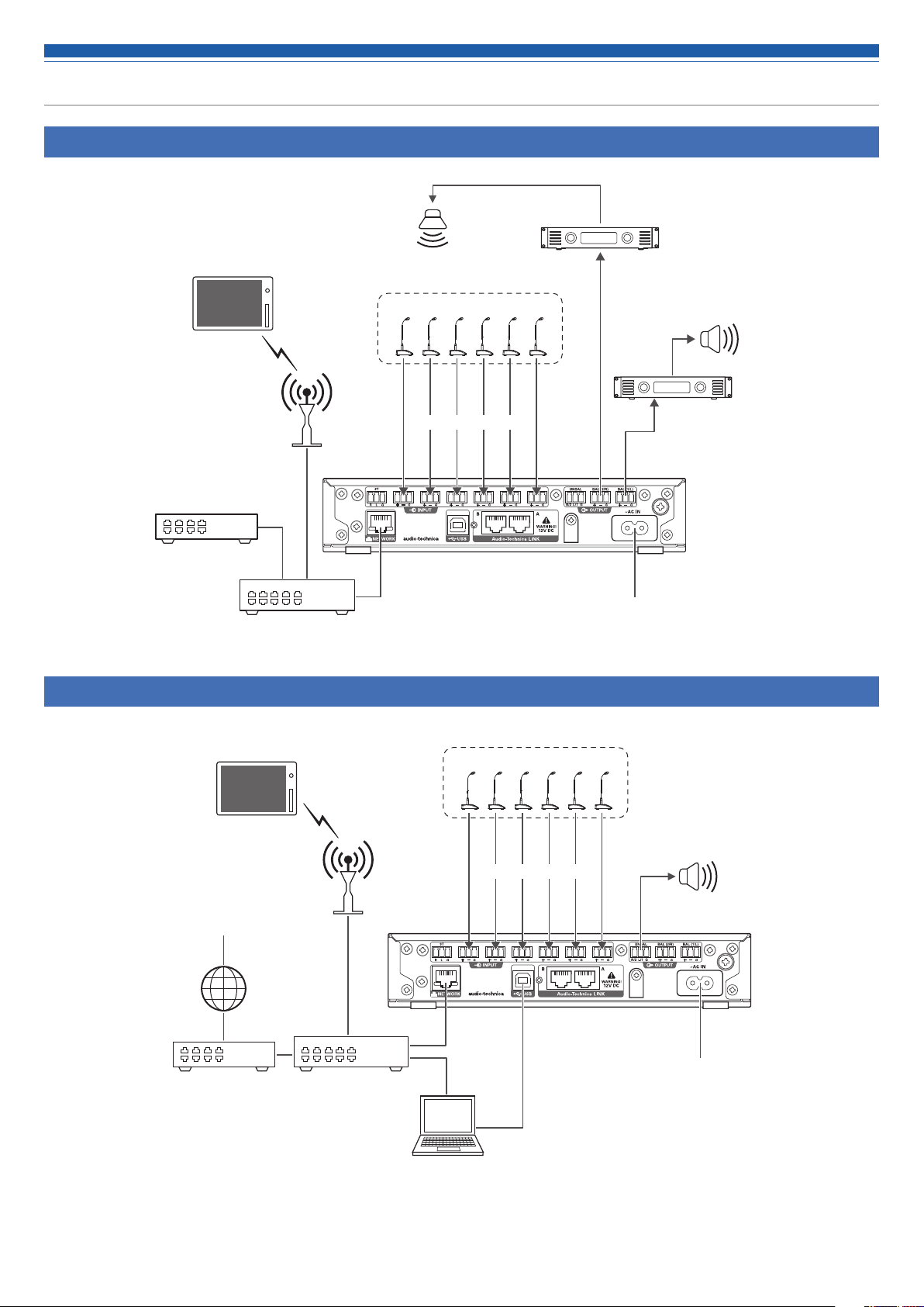
Local discussion (Preset #2) ........................................................................... 10
Remote discussion - web conference (Preset #3) ........................................ 10
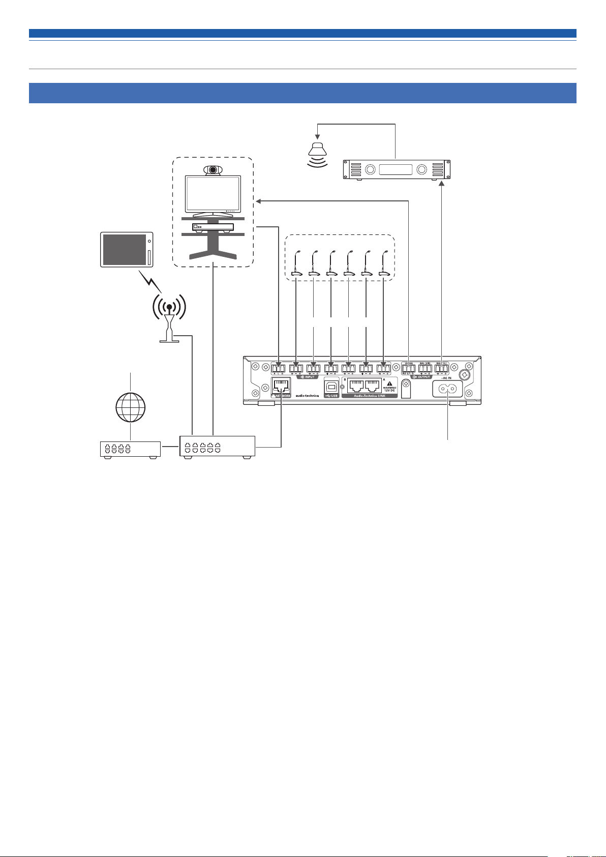
Remote discussion - video conference (Preset #4) ...................................... 11
Part names and function ................................................................... 12
Front panel ....................................................................................................... 12
Rear panel ........................................................................................................ 13
Using the product .............................................................................. 14
Starting the product ........................................................................................ 14
Front panel mode ............................................................................................ 14
Changing the front panel mode (operator mode/advanced mode) ........... 14
Selecting a function ........................................................................................ 14
Operations that can be performed in operator mode/advanced mode ..... 15
Operations available only in advanced mode .............................................. 15
Changing the IP config mode (Auto/Static) .................................................. 16
Locking the front panel ................................................................................... 17
Checking the firmware version ...................................................................... 17
Web Remote ....................................................................................... 18
What Is Web Remote? ..................................................................................... 18
What is "Locate"? ............................................................................................ 18
Recommended environment .......................................................................... 18
Preparing Web Remote ................................................................................... 18
Overview of Web Remote ............................................................................... 19
Launch/Log into Web Remote ........................................................... 20
Launching Web Remote .................................................................................. 20
Login screen .................................................................................................... 20
Logging into Web Remote .............................................................................. 20
Logging out of Web Remote .......................................................................... 20
Operator screen .................................................................................. 21
Administrator screen ......................................................................... 22
Header .............................................................................................................. 22
Indicators ......................................................................................................... 23
How to view audio input and output screens .............................................. 24
Setting the audio input details ......................................................... 25
Changing the input type (MIC/LINE) .............................................................. 25
Adjusting the gain ........................................................................................... 25
Turning the phantom power ON/OFF ............................................................ 25
Turning the phase ON/OFF ............................................................................. 25
Turning the low-cut ON/OFF .......................................................................... 25
Turning the 4-band EQ ON/OFF ..................................................................... 25
Adjusting the 4-band EQ ................................................................................ 26
Turning the AEC ON/OFF ................................................................................ 27
Checking SmartMixer status .......................................................................... 27
Turning the bus assignment ON/OFF ............................................................ 27
Setting channel names and colors ................................................................ 28
Turning the mute ON/OFF .............................................................................. 28
Adjusting the input level ................................................................................ 28
Setting the audio output details ...................................................... 29
Setting the unity level ..................................................................................... 29
Turning the FBS ON/OFF ................................................................................ 29
Turning the EQ ON/OFF .................................................................................. 29
Adjusting the FBS/EQ ..................................................................................... 29
Turning the dynamics function ON/OFF ....................................................... 32
Adjusting the dynamics .................................................................................. 32
Turning the delay function ON/OFF ............................................................... 34
Setting the delay time for delay function ..................................................... 34
Setting channel names and colors ................................................................ 34
Adjusting the output level .............................................................................. 35
Setting the USB output ................................................................................... 35
Setting the system details (Settings & Maintenance) ................... 36
Basic operations .............................................................................................. 36
Settings & Maintenance screen ..................................................................... 36
General in System Settings ............................................................................ 37
Network in System Settings ........................................................................... 38
User Access in System Settings .................................................................... 39
Audio in System Settings ............................................................................... 40
Front Panel in System Settings ...................................................................... 41
Utilities in System Settings ............................................................................ 42
Operator Page in Operator Access ................................................................ 43
Presets in Presets ............................................................................................ 44
4 Band EQ Library in Presets ......................................................................... 45
12 Band EQ Library in Presets ....................................................................... 46
Logging in Logging ......................................................................................... 47
System Info in System Info ............................................................................ 48
Key functions ...................................................................................... 49
AEC (Acoustic Echo Canceler) ........................................................................ 49
1
Page 3

Contents
SmartMixer ...................................................................................................... 52
Audio-Technica LINK ....................................................................................... 55
Front panel operation restriction ................................................................... 58
Recalling Preset ............................................................................................... 59
About preset .................................................................................................... 60
Copying settings ............................................................................................. 63
Resetting settings ............................................................................................ 64
Linking channels .............................................................................................. 65
Menu Item ........................................................................................... 66
Audio Settings ................................................................................................. 66
Settings & Maintenance ................................................................................. 70
Troubleshooting .................................................................................. 72
ATDM-0604 unit ............................................................................................... 72
Web Remote .................................................................................................... 73
Error messages ................................................................................... 74
Dimensions ......................................................................................... 75
Specifications ..................................................................................... 76
General specifications .................................................................................... 76
Audio ................................................................................................................ 76
/Output specifications ............................................................................ 77
Input
System diagram ................................................................................. 78
2
Page 4

Introduction
Thank you for purchasing this Audio-Technica product.
Before using the product, read through this user manual to ensure that you will use the product correctly. Please keep this manual for future
reference.
Checking the package contents
Before use, check to make sure that all of the following items are contained in the package.
If any of the items is missing from your package or damaged, contact your local Audio-Technica dealer.
• ATDM-0604 unit
• Euroblock connector ×10
• Rack-mount (large, small)
• Rack-mount screw ×6
• Power cable
• Rubber feet ×4
• Quick Start Guide
Trademarks
• SMARTMIXERTM is a trademark or registered trademark of Audio-Technica Corporation.
• Apple and the Apple logo are trademarks of Apple Inc., registered in the U.S. and other countries.
• iOS is a trademark or registered trademark of Cisco in the U.S. and other countries.
• App Store is a service mark of Apple Inc.
• Google, the Google logo, Google Play, the Google Play logo, and Android
• All other company and product names that appear in this document are trademarks or registered trademarks of their respective owners.
TM
are trademarks or registered trademarks of Google Inc.
3
Page 5
Safety precautions
Important information
Warning:
To prevent fire or shock hazard, do not expose this apparatus to rain or moisture.
Caution:
Do not expose this apparatus to drips or splashes.
To avoid electric shock, do not open the cabinet.
Refer servicing to qualified personnel only.
Do not expose this apparatus to excessive heat such as that generated by sunshine, fire or other heat sources.
Do not subject this apparatus to strong impact.
This apparatus should be located close enough to the AC outlet so that you can easily grasp the power cord plug at any time.
In case of emergency, disconnect the power cord plug of this apparatus quickly.
Do not place any objects filled with liquids, such as vases, on this apparatus.
To prevent fire, do not place any naked flame sources (such as lighted candles) on this apparatus.
Do not install this apparatus in a confined space such as a bookcase or similar unit.
Install this apparatus only in the places with good ventilation.
This apparatus is not disconnected from the mains as long as it is connected to the AC outlet, even if the unit itself has been turned off.
For customers in the USA/Canada
CAUTION
RISK OF ELECTRIC SHOCK
DO NOT OPEN
Caution: To prevent electric shock, do not remove the cover. There are
no user-serviceable parts inside. Internal adjustments are for qualified
professionals only. Refer all servicing to qualified service personnel.
The lightning flash with arrowhead symbol, within an
equilateral triangle, is intended to alert the user to the
presence of uninsulated “dangerous voltage” within
the product’s enclosure that may be of sufficient
magnitude to constitute a risk of shock to persons.
The exclamation point symbol within an equilateral
triangle is intended to alert the user to the presence
of important operating and maintenance (servicing)
instructions in the literature accompanying the
product.
Important safety instructions
1) Read these instructions.
2) Keep these instructions.
3) Heed all warnings.
4) Follow all instructions.
5) Do not use this apparatus near water.
6) Clean only with dr y cloth.
7) Do not block any of the ventilation openings. Install in accordance with the manufacturer’s instructions.
8) Do not install near any heat sources such as radiators, heat registers, stoves, or other apparatus (including amplifiers) that produce heat.
9) Do not defeat the safety purpose of the polarized or grounding plug. A polarized plug has two blades with one wider than the other. A
grounding plug has two blades and a third grounding prong. The wide blade or the third prong is provided for your safety. If the provided plug
does not fit into your outlet, consult an electrician for replacement of the obsolete outlet.
10) Protect the power cord from being walked on or pinched particularly at plugs, convenience receptacles, and the point where they exit from the
apparatus.
11) Only use attachments/accessories specified by the manufacturer.
12) Use only with a cart, stand, tripod, bracket, or table specified by the manufacturer, or sold with the apparatus.
13) When a cart is used, use caution when moving the cart/apparatus combination to avoid injury from tip-over.
14) Unplug this apparatus during lightning storms or when unused for long periods of time.
15) Refer all servicing to qualified service personnel. Servicing is required when the apparatus has been damaged in any way, such as power-supply
cord or plug is damaged, liquid has been spilled or objects have fallen into the apparatus, the apparatus has been exposed to rain or moisture,
does not operate normally, or has been dropped.
12)
4
Page 6

Safety precautions
FCC notice
Warning:
This device complies with Part 15 of the FCC Rules. Operation is subject to the following two conditions: (1) This device may not cause harmful
interference, and (2) this device must accept any interference received, including interference that may cause undesired operation.
Caution:
You are cautioned that any changes or modifications not expressly approved in this manual could void your authority to operate this equipment.
Note:
This equipment has been tested and found to comply with the limits for a Class B digital device, pursuant to part 15 of the FCC Rules. These
limits are designed to provide reasonable protection against harmful interference in a residential installation. This equipment generates, uses and
can radiate radio frequency energy and, if not installed and used in accordance with the instructions, may cause harmful interference to radio
communications. However, there is no guarantee that interference will not occur in a particular installation. If this equipment does cause harmful
interference to radio or television reception, which can be determined by turning the equipment off and on, the user is encouraged to try to correct
the interference by one or more of the following measures:
– Reorient or relocate the receiving antenna.
– Increase the separation between the equipment and receiver.
– Connect the equipment into an outlet on a circuit different from that to which the receiver is connected.
– Consult the dealer or an experienced radio/TV technician for help.
For customers in Canada
IC statement
CAN ICES-3 (B)/NMB-3 (B)
5
Page 7

Notes on use
About the product
• When using the product, also read the user manuals supplied with the devices that are to be connected.
• When not using the product, remove the power plug from the power outlet.
• Turn the product off before connecting or disconnecting cables.
• If you use the product near a TV or radio antenna, noise may be generated in the TV or radio. In this case, move the product away from the TV or
radio antenna.
Maintenance
• If the product becomes dirty or dusty, disconnect the power plug first, and then wipe the product off with a dry soft cloth.
• Do not use benzine, thinner, contact restoring protective agent, or any other chemical agent. Doing so may cause deformation, damage, or
malfunction.
• When storing the product for an extended period of time, wrap it with a plastic cover, and do not allow it to be exposed to humidity.
6
Page 8

Features
Features of ATDM-0604
• 4 Mic inputs, 2 Mic/Line inputs, 1 unbalanced stereo input
• 2 balanced outputs, 1 unbalanced stereo output
• USB audio I/O (1 stereo input and 1 stereo output)
• Built-in SmartMixer that allows for a selection between gain sharing and gate modes
• Equipped with an echo canceler and a noise canceler that can be used simultaneously (with up to 6 Mic inputs)
• Includes a 4-band EQ for each input channel, and a 12-band EQ for each output channel
• Equipped with a compressor, a limiter, and a 8-band feedback suppressor for each output channel
• Audio input/output settings can be configured on the front panel, whereas the advanced settings can be configured on a computer using Web Remote.
• Allows for external control with IP Remote Protocol
About Audio-Technica LINK
Up to six ATDM-0604 model mixers can be daisy-chained so that, as a whole system, it can handle audio inputs from 24 Mic channels, 12 Mic/Line
channels, and 6 unbalanced stereo channels.
The proprietary Audio-Technica LINK functionality enables the transmission of low-latency, high-speed audio bus signals between devices, making
it possible to steadily control and transmit uncompressed audio signals. Furthermore, the model offers excellent workability as it conforms to the
Ethernet standards and can be connected to generic LAN cables (shielded cables of Cat5e or above with the conductor diameter size of 24 AWG or
larger are recommended).
System installation
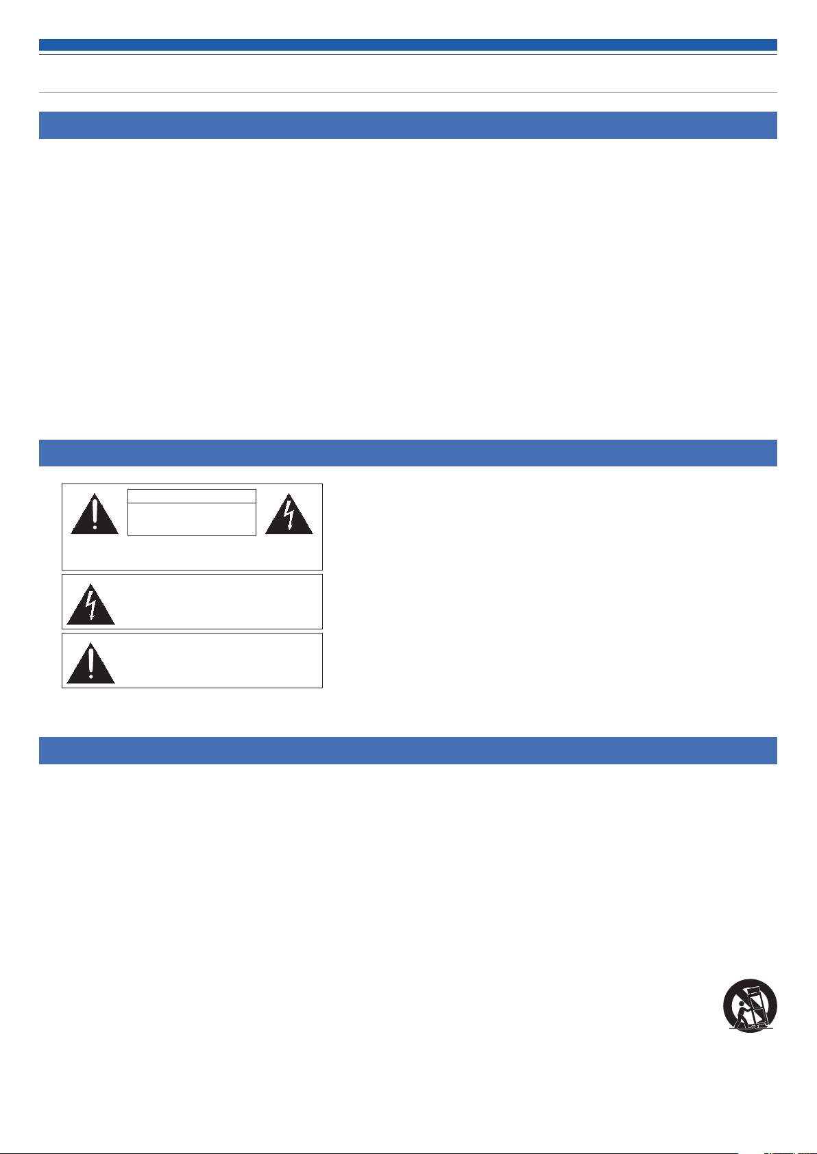
Installing on a rack
The product can be installed using the supplied rack-mount.
• When installing the product on a rack, make sure that the temperature inside the rack does not reach or exceed 40°C. Higher temperatures may
negatively affect the internal parts of the product, causing the product to malfunction.
• Ensure at least a 10-centimeter space between the product and other devices or the top, side, and back faces of the rack.
• The required rack specifications are as follows.
– EIA-standard 19-inch rack
– 1U-size attachable rack
– Rack with a shelf on which the product is placed or a guide rail that supports the product
• The rack mounts are affixed to the product with the following screws. Check the following when using screws other than those supplied.
– S-tight (tapping screw), nominal diameter 4 × 6 mm
7
Page 9
System installation
Rack-mount screw x 6
(supplied with the product)
Rack mount (large)
(supplied with the product)
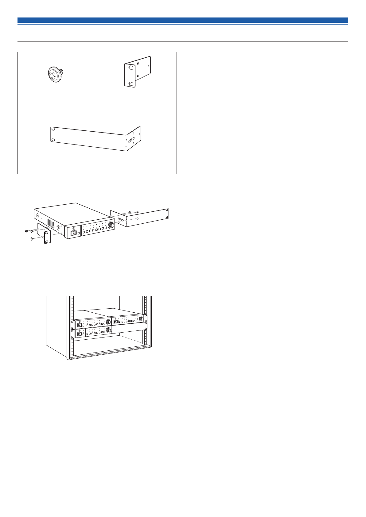
1. Attach the rack mounts to the product.
2. Install the product on the rack.
• To install the product on the rack, use the screws supplied with the rack or
commercially available screws.
Rack mount (small)
(supplied with the product)
8
Page 10
System installation
Unbalanced connection
An unbalanced connection tends to be subject to induction noise caused by the chassis potential differences. Be sure to match the chassis
potentials between devices.
• Match the power supply phases between devices.
• Standardize the power supply systems.
• Connect the GND (ground) terminal or chassis of each device.
Power cable connection
• Connect the power plug to the appropriate outlet with protective grounding. Electric shock may result if the plug is not grounded securely.
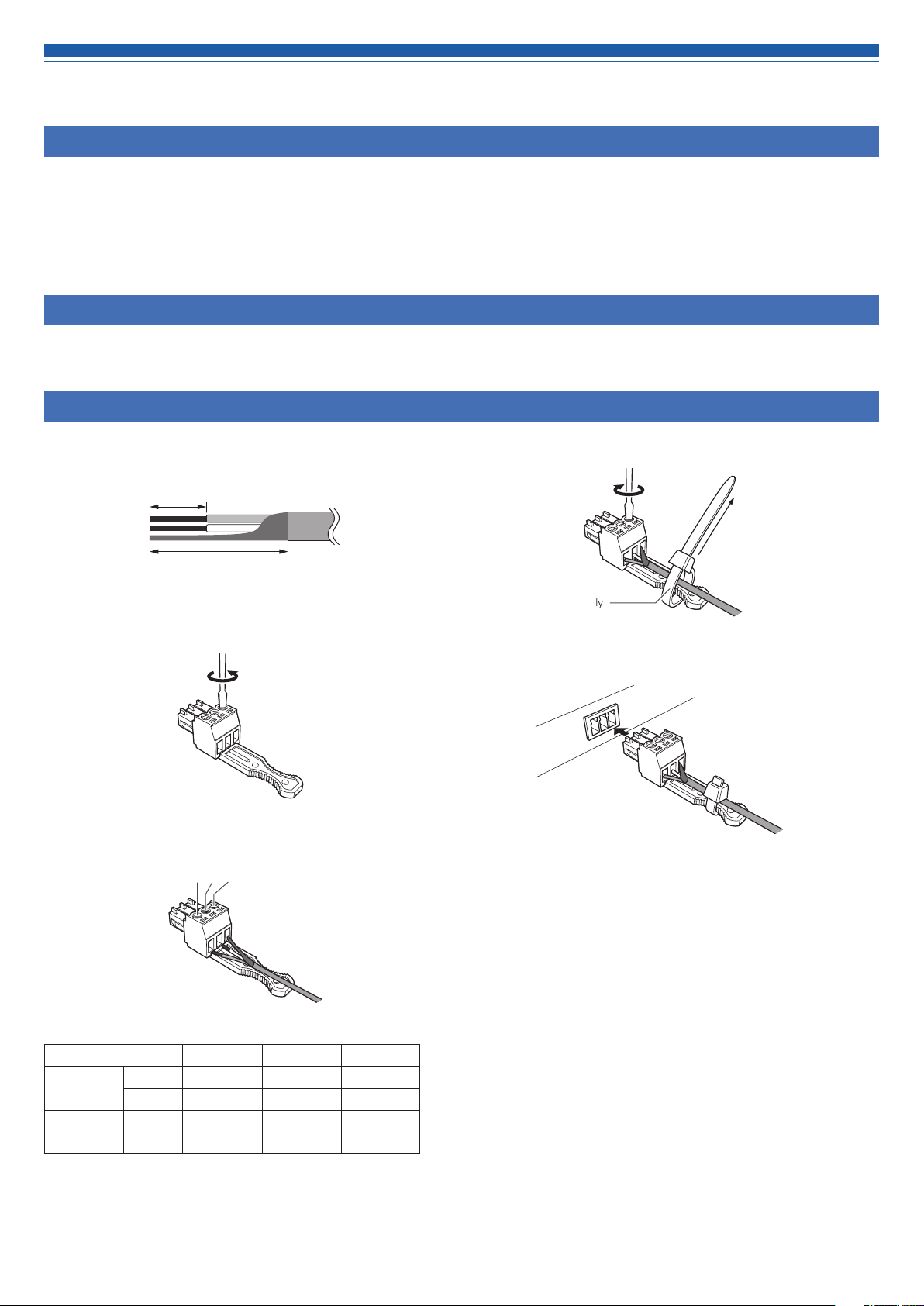
How to connect a Euroblock connector
1. As shown in the figure, expose the wires inside the cable.
• Do not solder the stranded wires.
Approx. 5 mm
Approx. 20 mm
2. Loosen the screws with a flathead screwdriver.
3. Verify the pin assignments, and connect each to the applicable
wire.
1 2 3
4. Tighten the screws and bundle the wires with a cable tie.
Use any commercially
available cable tie.
5. Connect the Euroblock connector to the product.
• Pin assignments
INPUT
OUTPUT
1 to 6 +: HOT –: COLD G: GND
ST R: RIGHT L: LEFT G: GND
1/L, 2/R +: HOT –: COLD G: GND
UNBAL R: RIGHT L: LEFT G: GND
1 2 3
9
Page 11
System connection examples
Local discussion (Preset #2)
Ceiling speaker
Tablet / Smartphone
Web Remote
for operator
Router
AP
Switching hub
Near-end source
Balanced audio cable
Remote discussion - web conference (Preset #3)
Mic
Power amplifier
Main speaker
Power amplifier
Balanced audio cable
Balanced audio cable
AC power cableEthernet cable
AC power
Tablet / Smartphone
Web Remote
for operator
Far-end source
Internet
Near-end source
Mic
AP
Balanced audio cable
cable
Switching hubRouter
Computer
Powered speaker
Unbalanced audio cable
AC power cableUSB cable Ethernet
AC power
10
Page 12
System connection examples
Remote discussion - video conference (Preset #4)
Tablet / Smartphone
Web Remote
for operator
Far-end source
AP
Internet
Far-end source
Video conference
system
Ceiling speaker
Near-end source
Mic
Balanced audio cable
Unbalanced audio cable
Power amplifier
Unbalanced audio cable
Balanced audio cable
AC power cableEthernet cable
AC power
Switching hubRouter
11
Page 13
Part names and function
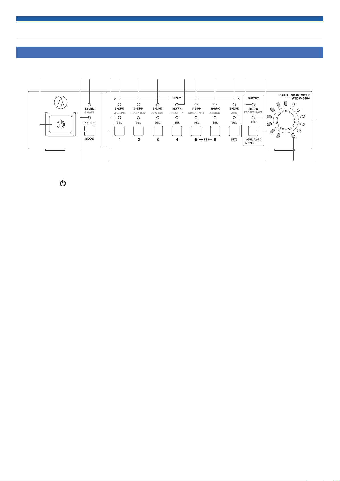
Front panel
❶
❷ ❸ ❹ ❺ ❻ ❼ ❽ ❾ ❿ ⓫ ⓭⓬
⓮ ⓯ ⓰ ⓲⓱
Power button ( )
❶
Turns on/off the power to the product.
PRESET LED
❷
Lights and blinks when the power is turned on and indicates that
the product is being started.
Lights when a preset is being recalled.
LEVEL·GAIN LED
❸
Lit: You can adjust the input level and output level.
Blinking: You can adjust the gain.
INPUT SEL LED
❹
Indicates the input channel, preset bank number, and the status of
the function/setting of each channel.
SIG/PK·MIC/LINE LED
❺
Indicates the signal level of input channel 1 when the level or gain
is being adjusted.
Also lights when the input type is changed (MIC/LINE).
SIG/PK·PHANTOM LED
❻
Indicates the signal level of input channel 2 when the level or gain
is being adjusted.
Also lights when on/off of the phantom power is set.
SIG/PK·LOW CUT LED
❼
Indicates the signal level of input channel 3 when the level or gain
is being adjusted.
Also lights when on/off of the low-cut is set.
SIG/PK·PRIORITY LED
❽
Indicates the signal level of input channel 4 when the level or gain
is being adjusted.
Also lights when on/off of the priority is set.
SIG/PK·SMART MIX LED
❾
Indicates the signal level of input channel 5 when the level or gain
is being adjusted.
Also lights when on/off of the SmartMixer is set.
SIG/PK·ASSIGN LED
❿
Indicates the signal level of input channel 6 when the level or gain
is being adjusted.
Also lights when on/off of the output bus assignment is set.
SIG/PK·AEC LED
⓫
Indicates the signal level of input channel ST when the level or gain
is being adjusted.
Also lights when on/off of the AEC is set.
SIG/PK·PRESET SAVE LED
⓬
Indicates the signal level of an output channel when the level or
gain is being adjusted.
Also lights when a preset is saved.
OUTPUT SEL LED
⓭
Indicates if an output channel is selected.
MODE button
⓮
Selects a function.
INPUT SEL button
⓯
Selects an input channel or preset number.
OUTPUT SEL button
⓰
Selects the output channel. Lights green for Output 1, red for
Output 2, or yellow for Output ST.
Volume LED
⓱
Indicates the current setting of the selected channel when the level
or gain is being adjusted.
Dial button
⓲
Turn the dial button to select, and push to confirm the selection.
12
Page 14
Part names and function
• An LED can be in one of five statuses.
(1) Lit: Indicates that a function is selected and enabled, etc.
(2) Off: Indicates that a function is not selected and disabled, etc.
(3) Blinking: Indicates that a function is being selected. Repeats every 500 ms until the status changes.
(4) Blinking fast: Indicates that the operation has been rejected. Repeats blinking five times every 200 ms.
(5) Dimmer lit: Indicates lower brightness.
• The signal level ranges indicated by the SIG/PK LEDs are as follows.
- LED lit (red): 0 dBFS to -5 dBFS
- LED lit (yellow): -6 dBFS to -24 dBFS
- LED lit (green): - 25 dBFS to - 59 dBFS
- LED off: -60 dBFS or less
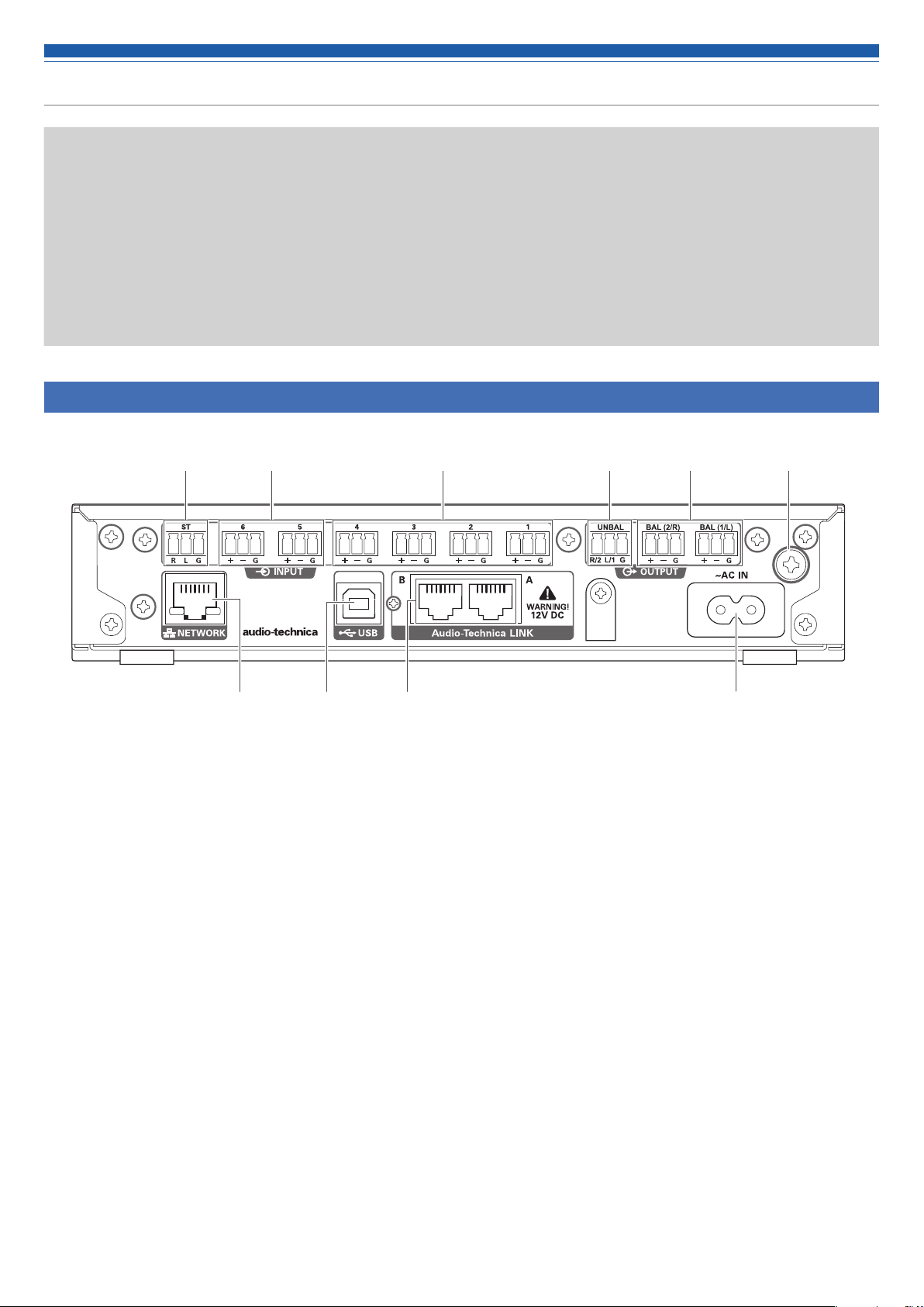
Rear panel
❶ ❸❷ ❹
❼
Unbalanced input port (ST)
❶
An unbalanced input port. Connect an unbalanced cable.
Pin assignments are as follows. 1: STEREO R 2: STEREO L and 3:
GND.
Balanced input port (MIC/LINE)
❷
A balanced input port. Connect a balanced cable. The input type
setting (MIC/LINE) can be changed.
Pin assignments are as follows. 1: HOT, 2: COLD, and 3: GND.
Balanced input port (MIC)
❸
A balanced input port. Connect a balanced cable.
Pin assignments are as follows. 1: HOT, 2: COLD, and 3: GND.
Unbalanced output port (UNBAL)
❹
An unbalanced output port. Connect an unbalanced cable.
Pin assignments are as follows. 1: STEREO R/2 2: STEREO L/1 and
3: GND.
Balanced output port (BAL 1/L·2/R)
❺
A balanced output port. Connect a balanced cable.
Pin assignments are as follows. 1: HOT, 2: COLD, and 3: GND.
❽ ❾ ❿
❺ ❻
❻ Groundingscrew
The supplied power cable is a 2-core cable, and cannot be used for
grounding. Ground the product as necessary.
NETWORK port
❼
A NETWORK port. Connect an Ethernet cable (Cat5e or above).
USB port
❽
A USB port (USB Type B). Connect a USB cable.
LINK A/B port
❾
A LINK A/B port. Used for Audio-Technica LINK.
Connect an Ethernet cable (Cat5e or above with 24 AWG or larger ;
shielded cable recommended). PoE will be available in a future
software update.
The maximum current supplied is 0.24A per port.
AC inlet
❿
Connect the power cable.
13
Page 15
Using the product
Starting the product
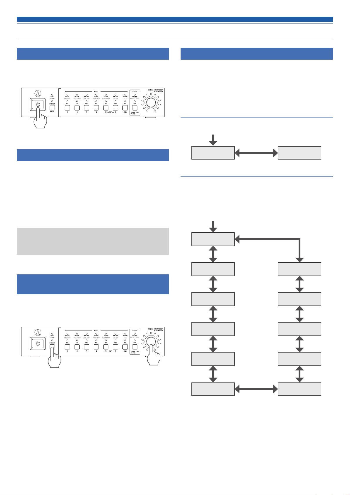
1. Press the power button.
• The PRESET LED lights, blinks, and LEVEL·GAIN LED turns on. Then, the
PRESET LED turns off, and the product starts in operator mode.
Front panel mode
The following two modes are available for operating the product by
using the buttons and the dial on the front panel.
Operator mode:
In this mode, daily operations are performed, such as loading the preset
settings and adjusting the audio level.
Advanced mode:
In this mode, advanced settings can be configured by installing and
implementing the product on site.
Selecting a function
Press the MODE button, or turn the dial button while pressing the
MODE button, to select the function.
• Determine the function selected based on the LED that lights (LEVEL·GAIN
LED and PRESET LED, or an LED from SIG/PK·MIC/LINE to SIG/PK·PRESET
SAVE).
Functions available in operator mode
Start of function
selection
LEVEL PRESET
Functions available in advanced mode
Press the MODE button to change the function in the clockwise
direction as shown in the figure. While pressing the MODE button, turn
the dial button to change the function to the one in the direction of the
dial.
Start of function
selection
• When the power is turned on, the product usually starts in
operator mode. This prevents accidental device setting changes
or other troubles, and ensures safe operation of the system.
Changing the front panel mode (operator mode/advanced mode)
Change between operator mode and advanced mode.
1. While pressing the MODE button, press and hold the dial button
(for 1 or more seconds).
2. LEDs light/blink/turn off, and the front panel mode changes.
• When changing to operator mode
(1) The LEVEL·GAIN LED and the PRESET LED light.
(2) The PRESET LED turns off.
(3) The front panel mode changes to operator mode.
GAIN
PRESET
PRESET SAVE
AEC
ASSIGN
SMART MIX PRIORITY
LEVEL
MIC/LINE
PHANTOM
LOW CUT
• When changing to advanced mode
(1) The LEVEL·GAIN LED, the PRESET LED, and the LEDs from SIG/
PK·MIC/LINE to SIG/PK·PRESET SAVE become lit.
(2) All LEDs turn off except the LEVEL·GAIN LED, which blinks.
(3) The front panel mode changes to advanced mode.
14
Page 16

Using the product
Operations that can be performed in operator mode/advanced mode
Recalling a preset
Recall saved preset data to change the current setting.
1. Select “PRESET”.
• The PRESET LED lights.
2. Push the INPUT SEL button to select the preset data to recall
(from 1 to 6).
• The INPUT SEL LED and the volume LED light.
3. Press the dial button.
• The preset data is read and the settings change.
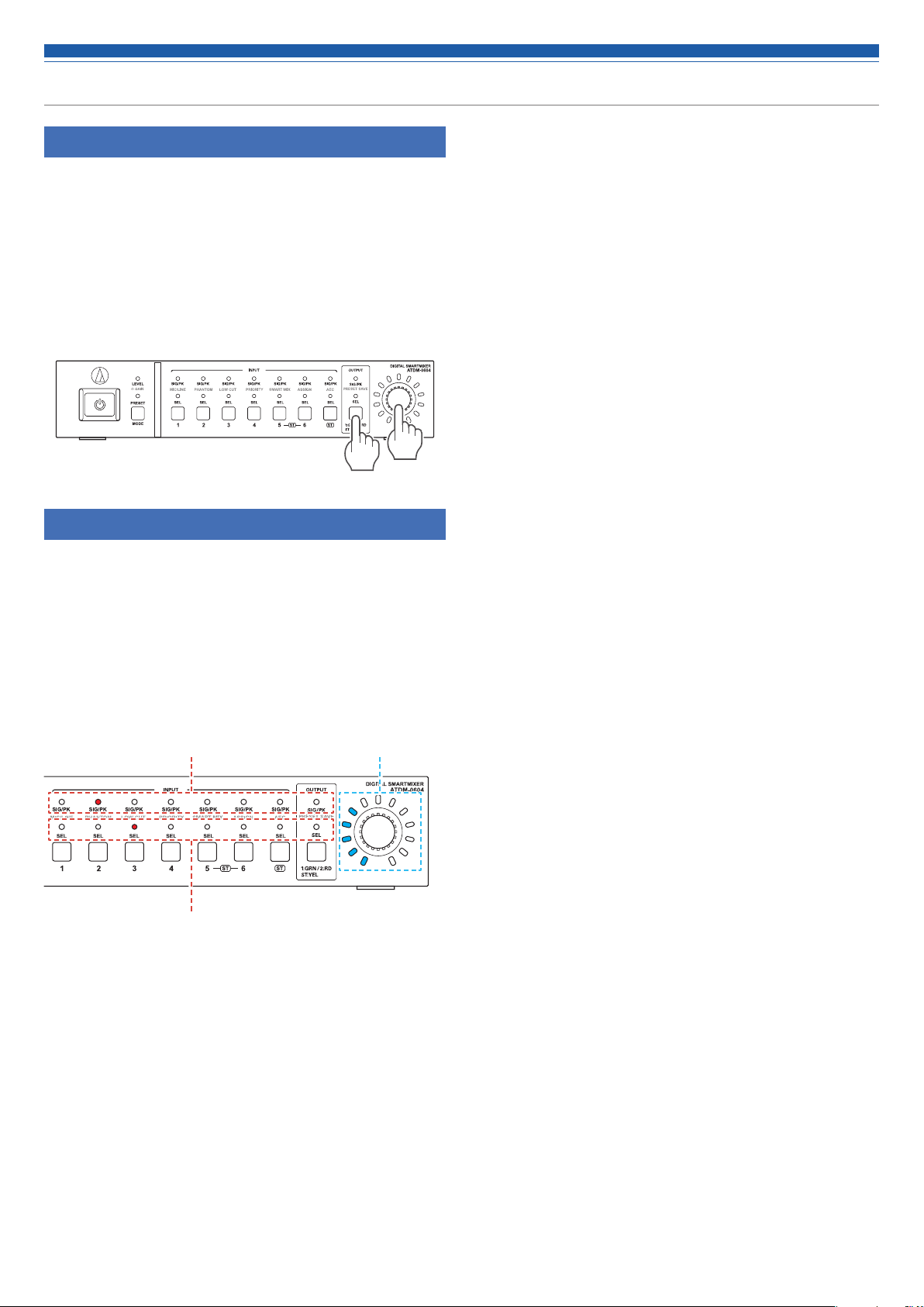
Adjusting the input level
Set the input level to MIC or LINE. If “LINE” input type is selected, PAD
(a function to attenuate the input signal by a certain level) is entered.
1. Select "LEVEL."
• The LEVEL·GAIN LED lights.
• The SIG/PK LED of each input channel becomes lit based on the input
level.
2. Press the INPUT SEL button to select the input channel you
want to adjust.
• The INPUT SEL LED lights, and the volume LED lights according to the
setting.
• The volume LED that indicates the 0 dB (-20 dBFS) point blinks.
3. Turn the dial button to adjust the input level.
• The volume LED becomes lit/turns off based on the adjusting operation.
• When the level is at the 0 dB (-20 dBFS) point, the blinking volume LED
becomes lit.
Adjusting the output level
Set the output level.
1. Select "LEVEL."
• The LEVEL·GAIN LED lights.
• The SIG/PK LED of the output channel becomes lit based on the output
level.
2. Push the OUTPUT SEL button to select the output channel you
want to adjust.
• The color of the OUTPUT SEL LED changes, and it lights according to the
selected output channel (OUTPUT 1: Green, OUTPUT 2: Red, OUTPUT ST:
Yellow). The volume LED lights according to the setting.
• The volume LED that indicates the 0 dB (-20 dBFS) point blinks.
3. Turn the dial button to adjust the output level.
• The volume LED becomes lit/turns off based on the adjusting operation.
• When the level is at the 0 dB (-20 dBFS) point, the blinking volume LED
becomes lit.
Operations available only in advanced mode
Change to advanced mode to perform these operations.
Changing the input type (MIC/LINE)
Specify the input type. Only input channel 5 and input channel 6 can be
set.
1. Select "MIC/LINE."
• The SIG/PK·MIC/LINE LED lights.
2. Press the INPUT SEL button to change the input type between
MIC and LINE (+4dBu).
• The INPUT SEL LED lights when LINE is selected, and it turns off when
MIC is selected.
Adjusting the gain
Set the input gain for MIC input.
1. Select "GAIN."
• The LEVEL·GAIN LED blinks.
• The SIG/PK LED of each input channel becomes lit based on the input
level.
2. Press the INPUT SEL button to select the input channel you
want to adjust.
• The INPUT SEL LED lights, and the volume LED lights according to the setting.
• The volume LED that indicates the -40 dB point blinks (only when ”MIC” is
selected as the input type).
3. Turn the dial button to adjust the gain.
• The volume LED becomes lit/turns off based on the adjusting operation.
• When the level is at the -40 dB point, the blinking volume LED becomes lit.
• During gain adjustment, press the dial button to switch the
volume LED display between gain setting value and level meter.
Change the display as necessary. Also, the unity level of each
audio output can be switched using the OUTPUT SEL button
and dial button.
Turning the phantom power ON/OFF
Turn on/off the phantom power (+48V). This setting can be made only
when the input type is set to “MIC”.
1. Select "PHANTOM."
• The SIG/PK·PHANTOM LED lights.
2. Press the INPUT SEL button to switch the phantom power
between ON and OFF.
• The INPUT SEL LED lights when the phantom power is turned on, and it
turns off when the phantom power is turned off.
Saving a preset
Save the current settings as a preset.
1. Select "PRESET SAVE."
• The SIG/PK·PRESET SAVE LED lights.
• If a preset is currently recalled, the INPUT SEL LED of that preset number
becomes lit.
2. Press the INPUT SEL button to select the saving location (from
PRESET 1 to PRESET 6).
• The INPUT SEL LED and the volume LED blink.
3. Press the dial button.
• The preset is saved to the specified saving location.
15
Page 17
Using the product
Turning the low-cut ON/OFF
Specify whether or not to remove low frequencies from the audio signal.
1. Select "LOW CUT."
• The SIG/PK·LOW CUT LED lights.
2. Press the INPUT SEL button to switch the low-cut between ON
and OFF.
• The INPUT SEL LED lights when the low-cut setting is turned on, and it
turns off when the low-cut setting is turned off.
Turning the priority ON/OFF
Set the channel priority. The priority can be set only when SmartMixer is
turned on, and gate mode is selected.
3. Select "PRIORITY."
• The SIG/PK·PRIORITY LED lights.
4. Press the INPUT SEL button to switch the priority between ON
and OFF.
• The INPUT SEL LED lights when the priority is turned on. The INPUT SEL
LED turns off when the priority is turned off.
Turning SmartMixer enable/disable
Switch SmartMixer between enable/disable.
Set SmartMixer mode (gate mode or gain sharing mode) via Web
Remote (p.52).
1. Select "SMART MIX."
• The SIG/PK·SMART MIX LED lights.
2. Press the INPUT SEL button to switch the SmartMixer between
enable/disable.
• INPUT SEL LED lit:
The SmartMixer is turned enable and the audio of that channel is mixed in
gate mode or gain sharing mode.
• INPUT SEL LED off:
The SmartMixer is turned disable.
Turning the AEC ON/OFF
Turn on/off the AEC (Acoustic Echo Canceler).
1. Select "AEC."
• The SIG/PK·AEC LED lights.
2. Press the INPUT SEL button to switch the AEC between ON and
OFF.
• The INPUT SEL LED lights when the AEC is turned on, and it turns off
when the AEC is turned off.
• Press the INPUT SEL button for the input channel ST to switch the AEC
mode.
INPUT SEL LED of the input channel ST lit: AEC with NC
INPUT SEL LED of the input channel ST blinking: Noise Canceling
INPUT SEL LED of the input channel ST off: OFF
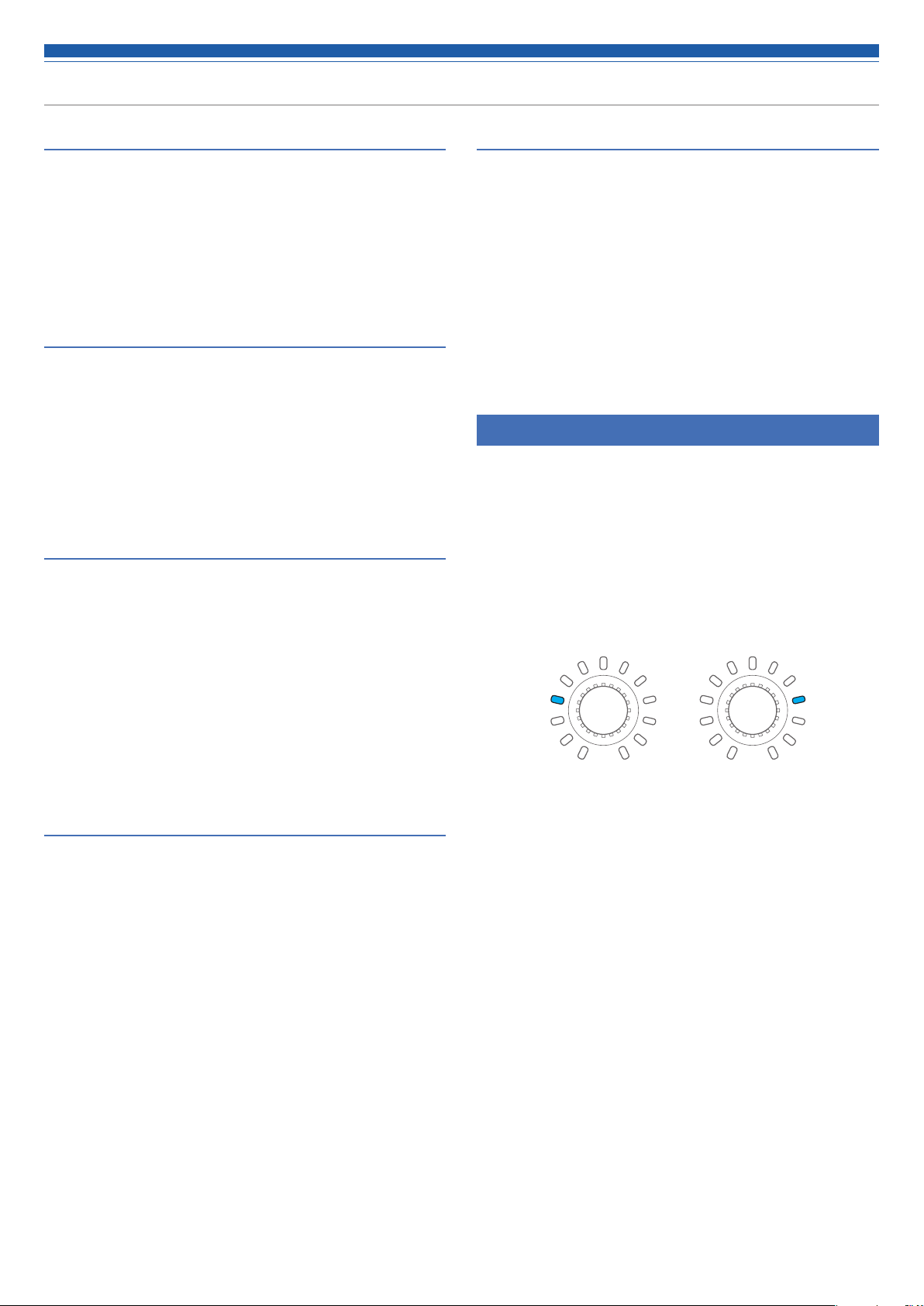
Changing the IP config mode (Auto/Static)
Specify how to obtain the IP address.
1. Press the power button.
• The PRESET LED becomes lit.
2. When the PRESET LED starts blinking, press down the MODE
button, the INPUT SEL button for INPUT channel 4 and the
OUTPUT SEL button.
3. When the LEVEL LED becomes lit, release the MODE button, the
INPUT SEL button for INPUT channel 4, and the OUTPUT SEL
button.
4. The volume LED lights according to the IP Config Mode setting.
Auto Static
Setting the bus assignment
Assign and confirm the output bus for an input channel.
1. Select "ASSIGN."
• The SIG/PK·AEC LED lights.
2. Press the OUTPUT SEL button to select the output bus to be
assigned and confirmed.
• The INPUT SEL LED lights when the channel is assigned to the selected
output bus. The INPUT SEL LED turns off when the channel is not
assigned.
• Press the INPUT SEL button to switch the bus assignment.
INPUT SEL LED lit:
Assigned to an output bus. Audio signals not processed by SmartMixer are
output even when SmartMixer is turned ON.
INPUT SEL LED blinking:
Assigned to an output bus. Audio signals processed by SmartMixer are
output when SmartMixer is turned ON.
INPUT SEL LED off:
Not assigned to any output bus.
5. Turn the dial button and change the IP Config Mode.
6. Restart the product.
16
Page 18
Using the product
Locking the front panel
A lock can be applied so that the front panel operation is disabled.
1. While pressing the OUTPUT SEL button, press and hold the dial
button (for 1 or more seconds).
• The front panel becomes locked. Repeat the same steps to disable the
lock and enable input/output level adjustment in operator mode or gain
adjustment in advanced mode.
• The PRESET LED, the LEVEL/GAIN LED, the INPUT SEL LED, and the
volume LED turn off.
• The OUTPUT SEL LED is on while the panel is locked.
• Other LEDs turn on based on the level of an audio input.
Checking the firmware version
You can view the firmware version of the product.
1. Press the power button.
• The PRESET LED becomes lit.
2. When the PRESET LED starts blinking, press and hold the
MODE button and the dial button.
3. When the LEVEL LED becomes lit, release the buttons.
• LEDs light according to the firmware version.
(Example) When the firmware version is “02.03.05”
Indicates “02”
Indicates “03”
4. Check the firmware version, and turn off the product.
Indicates “05”
17
Page 19
Web Remote
What Is Web Remote?
Web Remote is a web-based application for controlling this product. With
Web Remote, you can remotely perform the following tasks from your
Windows PC, Mac, iOS or Android device (hereinafter “control device”).
• Check the status of the product
• Change the various settings of the product
What is "Locate"?
"Locate" is a launcher application for Web Remote. Connect your control
device, then activate "Locate". With "Locate", you can quickly access Web
Remote without entering the IP address assigned to the product.
• You can also launch Web Remote without using "Locate".
Recommended environment
OS supporting Web Remote and "Locate"
• Microsoft Windows 7 or later
• Apple OS X 10.11 El Capitan or later
• Android OS 5.0 or later
• iOS 9 or later
Recommended web browsers for Web Remote
• Microsoft Internet Explorer 11 (Windows)
• Google Chrome ver. 57 or later (Windows and Android)
• Mozilla Firefox ver. 52 or later (Windows)
• Safari 10 or later (OS X and iOS)
• You can log into Web Remote from up to 3 control devices at
the same time. If two different web browsers are running on
one control device, Web Remote recognizes access from two
control devices.
• To exit Web Remote, make sure to log out first, and then close
the web browser screen. If the screen is closed without logging
out, the session may continue, and you may remain logged into
Web Remote.
• The minimum size of the web remote screen is 1024 x 768
pixels. For the control device, use a large enough display
monitor to display the Web Remote screen in the web browser.
• If IP addresses are obtained automatically when connecting
(1) Set the product’s IP Config Mode to "Auto".
– The product ships from the factory in "Auto" mode.
(2) Set the control device's network settings so that it connects to the
network.
• If static IP addresses are used when connecting
(1) Set the product’s IP Config Mode to "Static".
– The IP address is set to a static value.
The default value is "192.168.33.102".
2. Use a wired or wireless connection to connect the control
device to the product.
3. Turn on the control device and the product.
• If IP addresses are obtained automatically when connecting, it may take
some time before the IP address is set.
Setting up "Locate"
1. Download the "Locate" installer/application to the control
device.
• For Windows and Mac:
Download from the Audio-Technica website (www.audio-technica.com) for
your country or region.
• For iOS and Android:
Download from the App Store or Google Play.
Upon completion of the download, proceed to Step 4.
2. Double-click “setup.exe” you have downloaded.
• The Setup Wizard opens.
3. Follow the on-screen instructions to install "Locate".
• When installation is complete, the "Locate" icon appears on the desktop.
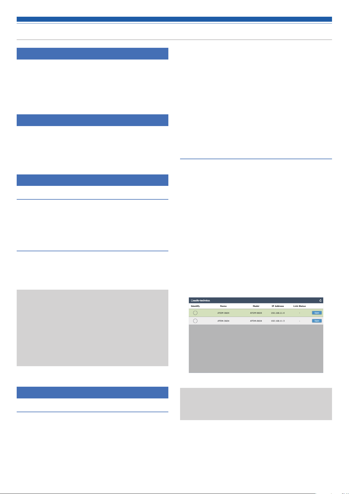
4. After confirming that the ATDM-0604 is powered up and
connected to the same network as the control device, doubleclick the "Locate" icon.
• "Locate" launches. All ATDM-0604s connected to the network are
automatically detected.
5. Select the ATDM-0604 you want to control via Web Remote, and
click “Open”.
• The Web Remote Login screen appears.
Preparing Web Remote
Connect a control device to the product
1. Before connecting a control device to the product, network
settings for both devices must be performed.
• When clicking the “Identify” button, the button will illuminate in
red, and the indicators on the front panel of the selected ATDM0604 will blink. Use this function to identify a specific ATDM0604 when multiple ATDM-0604s are connected to the system.
18
Page 20
Web Remote
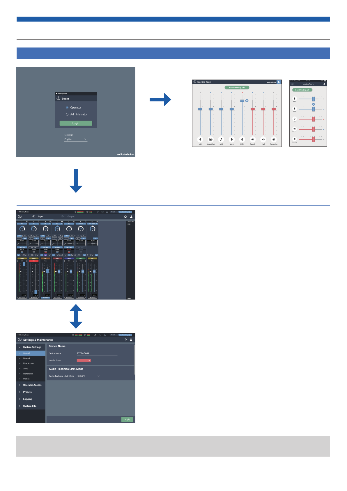
Overview of Web Remote
Login screen
Log in as the Administrator
Log in as the Operator
Windows/Mac display iOS/Android display
Audio setting
Input: Set the various options, such as Gain, Level, EQ, and SmartMixer,
for audio input from a microphone or other audio devices.
Output: Set the various options, such as Level, FBS, EQ, and Dynamics,
for audio output.
Settings & Maintenance
System Settings: Set the options relating to Network, Access Permissions, Audio-
Technica LINK, etc., and update the firmware.
Operator Access: Set the various options relating to the operation screens you can
access after logging in as the Operator.
Presets: Recall and save presets and import/export preset data to/from
external devices.
Logging: Set the options relating to log messages, and download log
messages.
System Info: System information, such as the various network settings and the
product's serial number and firmware version, is displayed.
• To log in as the administrator, you must use a Windows PC or a Mac computer. Operations using a tablet or a smartphone are not
guaranteed.
19
Page 21
Launch/Log into Web Remote
Launching Web Remote
Launching from "Locate"
1. Launch "Locate" you have installed in the control device.
2. From the list, select the ATDM-0604 for which you want to
launch Web Remote.
• Web Remote launches, and the Login screen appears.
Specifying an IP address to launch the Web Remote
If you know the IP address of the product, you can launch Web Remote
by specifying the IP address directly.
1. Open the control device’s web browser.
2. Enter the IP address of the ATDM-0604 for which you want to
launch Web Remote.
• Web Remote launches, and the Login screen appears.
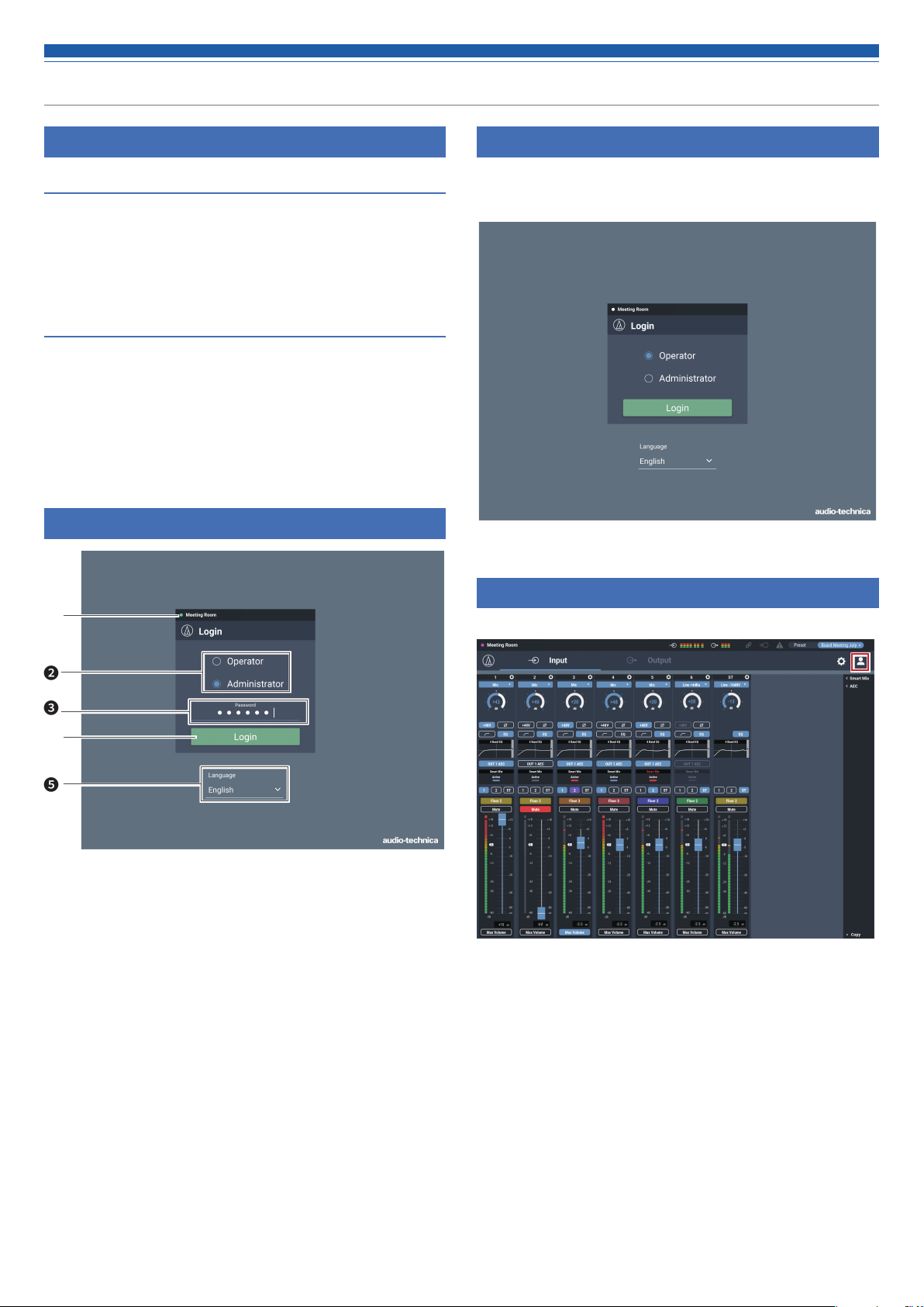
Login screen
Logging into Web Remote
1. Select “Operator” or “Administrator”, and then click “Login”.
• If “Administrator” is selected, the password entry field appears. Enter the
password, and then click “Login”.
❶
❷
❸
❹
❺
Device name
❶
The name set for the product is displayed.
Mode selection
❷
Select “Operator” or “Administrator” as the login user.
Password
❸
Enter the password.
• This field appears when login as the Administrator is locked. For
the password settings, refer to “Login Password” (p.39).
Login button
❹
Language
❺
Select the display language for Web Remote.
Logging out of Web Remote
1. Click the Logout icon.
2. Click “Log out”.
• Log out of Web Remote.
20
Page 22
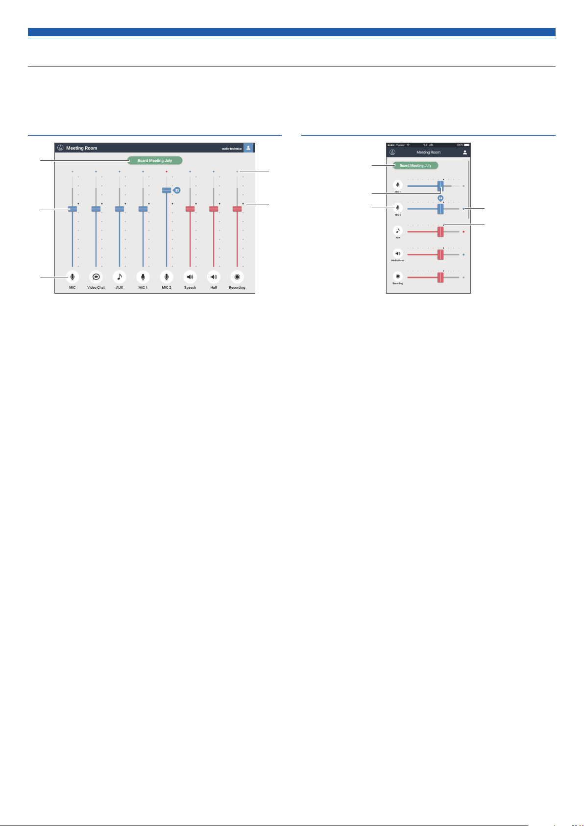
Operator screen
If you log in as the Operator, you can import the presets, adjust the volumes, and set other options required in day-to-day operations, through
simple steps.
Windows/Mac screen iOS/Android screen
❶
❷
❸
Preset display
❶
Click to recall a desired preset.
Volume dial
❷
Adjust the volume of each input/output channel.
Blue: Input channel
Red: Output channel
Input/Output icon
❸
The type and name of each input/output channel are displayed.
❹
❺
❶
❷
❸
❹
❺
Level meter
❹
The level of each channel is displayed.
• Input channel:
Blue: Input received
Gray: No input
• Output channel:
Blue: Level between -6 to -59 dBFS
Red: Level equal to or greater than -5 dBFS
Gray: No input
Reference point
❺
The balance is set as adjusted on the Audio Input Screen at the
reference point (70%).
21
Page 23
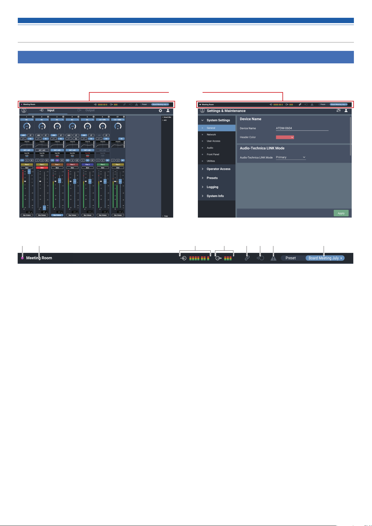
Administrator screen
Header
If you log in as the Administrator, you can access the input/output Settings and Settings & Maintenance screens.
The header at the top remains the same on both screens.
Header
Input Settings Settings & Maintenance
Device color
❶
This color helps you identify each device when multiple products
are operated.
Device name
❷
The name set for the product is displayed.
Input indicator
❸
The input level is displayed.
Output indicator
❹
The output level is displayed.
❸❶ ❷ ❹ ❺ ❻ ❼ ❽
Audio-Technica LINK status
❺
The Audio-Technica LINK connection status is displayed.
IP remote status
❻
The active status of IP control is displayed.
Error status
❼
An error status is displayed.
Preset
❽
The selected preset and the name of the loaded preset are
displayed.
22
Page 24
Administrator screen
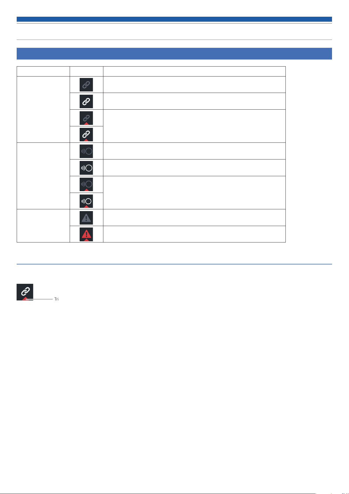
Indicators
Status Icon display Description of each status
The Audio-Technica LINK device is not connected correctly.
Audio-Technica LINK
status
IP remote status
Error status
Error display
The Audio-Technica LINK device is connected correctly.
There is an Audio-Technica LINK error.
Remote control is disabled.
Remote control is enabled.
There is a remote control error.
No error is present.
An error is present.
When a triangle mark is displayed on an icon, clicking the icon displays a description of the error. After checking the description of the error, move
the cursor away from the icon, and the triangle mark will disappear.
Triangle mark
23
Page 25

Administrator screen
How to view audio input and output screens
❸❶ ❷
❹ ❺ ❺❻
Click to view the Web Remote version and the Audio-Technica
❶
website.
Click to toggle between the Audio Input and Audio Output Settings
❷
screens.
Click to switch to the Settings & Maintenance screen.
❸
• You may not be able to set and/or operate functions depending on the settings or the conditions. If applicable, those functions are either
grayed out or hidden.
You can configure the audio input settings for each input channel.
❹
Click each of these items to display a detailed setting menu.
❺
“Smart Mix”: Refer to p.52.
“AEC”: Refer to p.50.
“USB OUT”: Refer to p.35.
You can configure the audio output settings for each output channel.
❻
24
Page 26

Setting the audio input details
Changing the input type (MIC/LINE)
Specify the input type.
1. Click the area in the red box on the screen shown below.
2. Select the input type from the pull-down menu.
• The input type changes.
Turning the phantom power ON/OFF
Turn ON/OFF the phantom power (+48V). This setting can be made only
when “Mic” is selected as the input type.
1. Click the area in the red box on the screen shown below.
• The function is turned ON (blue)/OFF (no color) each time the switch is clicked.
Turning the phase ON/OFF
Invert the input audio phase.
1. Click the area in the red box on the screen shown below.
• The function is turned ON (blue)/OFF (no color) each time the switch is clicked.
Adjusting the gain
Set the input gain for Mic input.
1. Drag the meter to adjust the gain.
• You can also click the number and enter the gain directly.
• The level meter displays the pre-fader level during gain
adjustment. Adjust the gain while checking this level.
Turning the low-cut ON/OFF
Specify whether or not to remove low frequencies from the audio signal.
1. Click the area in the red box on the screen shown below.
• The function is turned ON (blue)/OFF (no color) each time the switch is clicked.
Turning the 4-band EQ ON/OFF
Turn ON/OFF the 4-band EQ to be applied to audio inputs.
1. Click the area in the red box on the screen shown below.
• The function is turned ON (blue)/OFF (no color) each time the switch is clicked.
25
Page 27

Setting the audio input details
Adjusting the 4-band EQ
Set the 4-band EQ to be applied to audio inputs.
1. Click the area in the red box on the screen shown below.
• The Settings screen appears.
2. Set each item.
How to view settings screen (Expert Mode)
Save an EQ preset, reset the EQ frequency characteristics waveform,
❶
or switch the setting screen.
From the EQ library, recall the EQ preset.
❷
• If the EQ is adjusted after the data is recalled, the display becomes blank.
Display and edit the EQ frequency characteristics waveform.
❸
Change the gain by dragging a meter or directly entering a value.
❹
Change the frequency by dragging a meter or directly entering a
❺
value.
Change the Q value by dragging a meter or directly entering a value.
❻
Change the filter type.
❼
❶
❷
❸
❹
❺
❻
❼
Changing settings screen
The Settings screen can be in “Easy Mode” with a simplified display or
in “Expert Mode” with all items displayed.
Easy Mode Select from the pre-arranged EQ patterns to easily adjust the
EQ.
Expert Mode The parameters can be set for each band for ner EQ adjust-
ment.
Click the icon ( ) on the top right of the screen to switch between
the two.
How to view settings screen (Easy Mode)
❶
❷
❸
❹
Save an EQ preset, reset the EQ frequency characteristics waveform,
❶
or switch the setting screen.
Display the EQ frequency characteristics waveform.
❸
Select the audio type.
❸
Adjust the tone.
❹
26
Page 28
Setting the audio input details
Turning the AEC ON/OFF
Turn ON/OFF the AEC (Acoustic Echo Canceler).
1. Click the area in the red box on the screen shown below.
• The function is turned ON (blue)/OFF (no color) each time the switch is clicked.
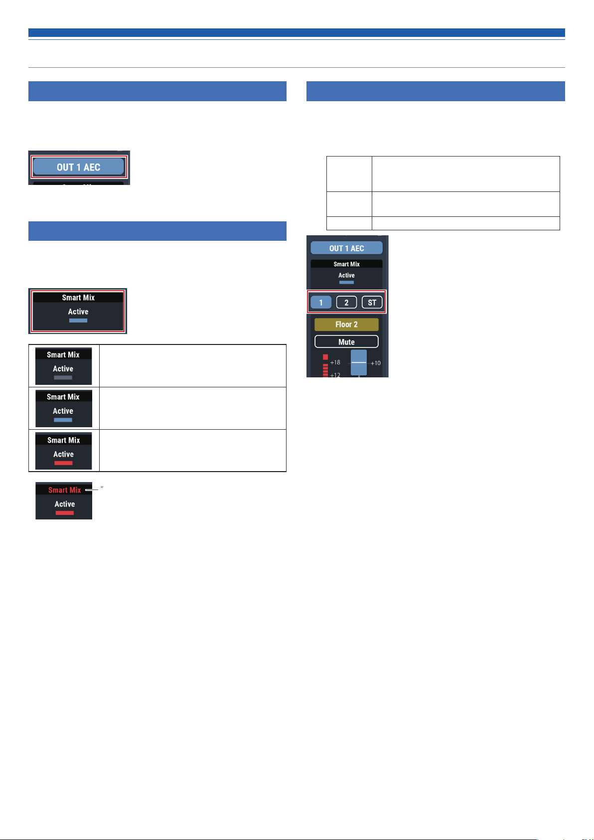
Checking SmartMixer status
2. Check the area in the red box on the screen shown below.
• Click on the screen to display the SmartMixer Settings screen. For more
details, refer to “SmartMixer” (p.52).
Turned OFF.
Turning the bus assignment ON/OFF
Switch the output bus between ON and OFF for each channel.
1. Click the area in the red box on the screen shown below.
• The function is turned ON (blue)/ON (purple)/OFF (no color) each time the
switch is clicked.
ON (Blue) Assigned to an output bus. Audio signals not
processed by SmartMixer are output even when
SmartMixer is turned ON.
ON
(Purple)
OFF Not assigned to any output bus.
Audio signals processed by SmartMixer are
output when SmartMixer is turned ON.
Turned ON.
Turned ON, and SmartMixer active.
”Priority” is turned ON if ”Smart Mix” is displayed in red.
27
Page 29

Setting the audio input details
Setting channel names and colors
Set the name and color of each channel.
1. Click the area in the red box on the screen shown below.
2. Select a color of your choice.
Adjusting the input level
Set the Mic/Line input level for each channel.
2. Drag the volume adjustment dial, and move it up and down to
adjust the input level.
Max Volume setting position
Volume adjustment dial
3. Click the text input field and enter the channel name of your
choice.
4. Click “OK”.
Turning the mute ON/OFF
Switch the mute setting between ON and OFF for each channel.
1. Click the area in the red box on the screen shown below.
• Mute turns ON (red)/OFF (no color) each time the switch is clicked.
Max Volume ON/OFF
Turning the max volume ON/OFF
Determine the Max Volume and turn it ON/OFF for each channel.
1. Click “Max Volume”.
• The setting is turned ON (blue)/OFF (no color) each time the dial is clicked.
• The fader maximum is set at the position when the Max Volume is turned
ON. The range above the specified position is grayed out. To change the
position, turn the Max Volume OFF and then back ON.
28
Page 30

Setting the audio output details
Setting the unity level
1. Click the area in the red box on the screen shown below.
2. Select a unity level from the pull-down menu.
• The unity level changes.
Turning the FBS ON/OFF
Switch the FBS (feedback suppressor) between ON and OFF for each
channel.
1. Click the area in the red box on the screen shown below.
• The function is turned ON (blue)/OFF (no color) each time the switch is clicked.
Adjusting the FBS/EQ
1. Click the area in the red box on the screen shown below.
• The Settings screen appears.
2. Set each item.
Turning the EQ ON/OFF
Switch the EQ between ON and OFF for each channel.
1. Click the area in the red box on the screen shown below.
• The function is turned ON (blue)/OFF (no color) each time the switch is clicked.
29
Page 31

Setting the audio output details
How to view settings screen (FBS)
❸ ❹ ❺ ❻
The statuses of the bands appear. You can also switch between
❶
dynamic and static.
Dynamic state.
• Indicates that the feedback frequency is detected, and the FBS is functioning.
• The feedback frequency remains for 15 seconds
and is then automatically cleared.
• Until a new frequency is detected, the feedback
frequency display is left blank and turns into a
standby state.
Static state.
• Click this icon in a dynamic state to lock the band
and enter a static state.
• Click the icon again to cancel a static state of the
band and enter a standby state.
❶
❷
The frequencies of the detected feedbacks appear.
❷
Select the strength to suppress the feedback.
❸
Select the speed of suppressing the feedback.
❹
Click to reset the detected frequencies. Once reset, new
❺
frequencies are detected (but those of the bands in a static state
are not reset).
Click to copy the static bands to the bands of 12-band EQ. The
❻
bands for which the 12-band EQ is turned off are copied.
• Switch the settings of “Detection” ( ❸ ) or “Response” (❹) to
reset the band frequencies in a dynamic state.
Standby state.
• Waiting for a new feedback frequency to be
detected.
30
Page 32
Setting the audio output details
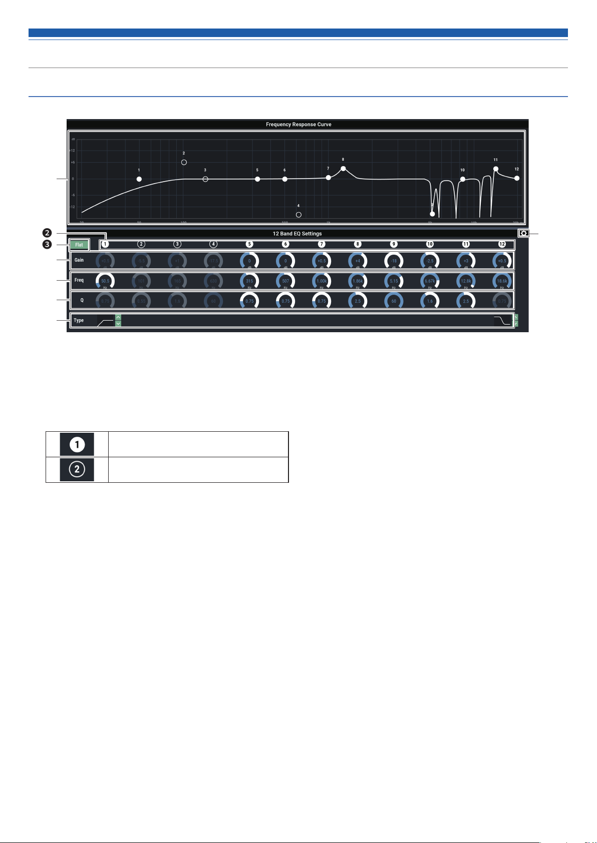
How to view settings screen (EQ)
❶
❷
❸
❹
❺
❻
❼
Display and edit the EQ frequency characteristics waveform. The
❶
pointer for each band indicates the frequency and the gain position.
• Edit the frequency and the gain by dragging a pointer.
Display and switch the ON/OFF setting of each band.
❷
The ON and OFF statuses indicate as follows.
Turned ON.
Turned OFF.
In all bands, change the gain to 0 without changing the current
❸
frequency.
Adjust the gain of each band.
❹
Adjust the frequency of each band.
❺
Adjust the Q value of each band.
❻
Change the filter type (applicable to bands 1 and 12 only).
❼
❽ Reset a parameter and save/recall an EQ preset.
❽
31
Page 33
Setting the audio output details
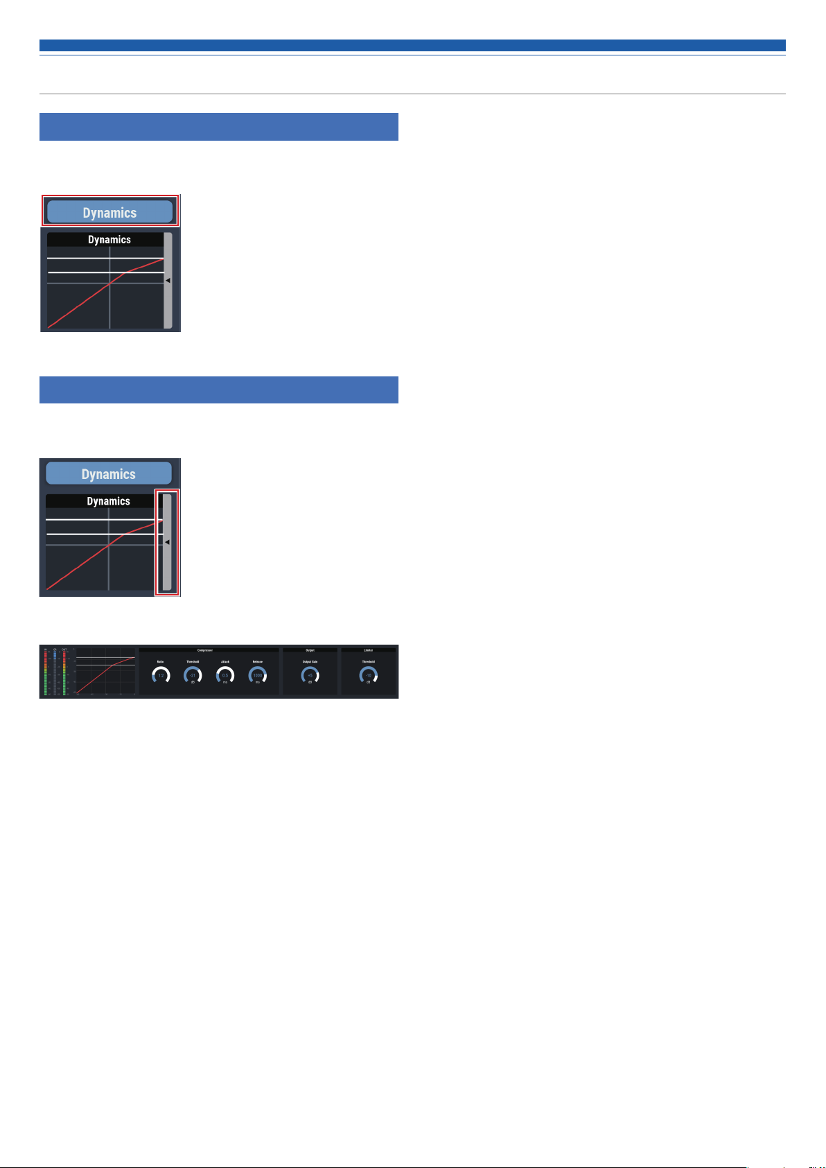
Turning the dynamics function ON/OFF
1. Click the area in the red box on the screen shown below.
• The function is turned ON (blue)/OFF (no color) each time the switch is clicked.
Adjusting the dynamics
1. Click the area in the red box on the screen shown below.
• The Settings screen appears.
2. Set each item.
32
Page 34
Setting the audio output details
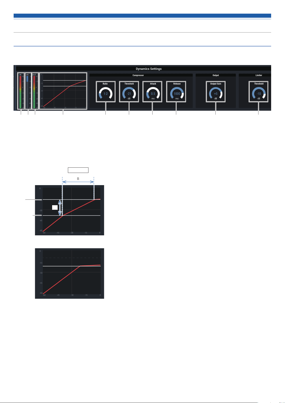
How to view settings screen (DYN)
❶ ❷ ❸ ❹ ❺ ❻ ❼ ❽ ❾ ❿
Indicates the level of audio input to Dynamics.
❶
Indicates the level of audio gain suppression by the compressor.
❷
Indicates the level of audio output from Dynamics.
❸
Indicates the Dynamics characteristic.
❹
A:B = Ratio
B
Limiter
threshold
Compressor
threshold
A
Set the compressor ratio.
❺
Set the compressor threshold.
❻
Set the compressor attack time.
❼
Set the compressor release time.
❽
Set the Dynamics output gain.
❾
Set the Limiter threshold.
❿
When the limiter threshold is lower than
the compressor threshold, the compressor
threshold is cleared, and only the limiter
threshold is displayed.
33
Page 35

Setting the audio output details
Turning the delay function ON/OFF
Specify whether or not to delay the output of each channel.
1. Click the area in the red box on the screen shown below.
• The function is turned ON (blue)/OFF (no color) each time the switch is clicked.
Setting the delay time for delay function
1. Set the amount of time to delay.
• Click / to adjust the time. You can also click the time and enter the
value directly.
Setting channel names and colors
Set the name and color of each channel.
1. Click the area in the red box on the screen shown below.
2. Select a color of your choice.
3. Click the text input field and enter the channel name of your
choice.
4. Click “OK”.
34
Page 36

Setting the audio output details
Adjusting the output level
Set the Mic/Line output level for each channel.
1. Click the volume adjustment dial, and move it up and down to
adjust the output level.
Max Volume setting position
Volume adjustment dial
Setting the USB output
Select the USB output bus and set the transmission level.
1. Click “USB OUT”.
2. Select the bus for USB output.
• You can select up to two sources from “1”, “2”, and “AEC”.
• If "ST” is selected, other sources cannot be selected.
Max Volume ON/OFF
Turning the max volume ON/OFF
Determine the Max Volume and turn it ON/OFF for each channel.
1. Click “Max Volume”.
• The function is turned ON (blue)/OFF (no color) each time the dial is clicked.
• The fader maximum is set at the position when the Max Volume is turned
ON. The range above the specified position is grayed out. To change the
position, turn the Max Volume OFF and then back ON.
3. Select the level for USB output.
• Click / to adjust the level. You can also click the number and enter
another value directly.
35
Page 37

Setting the system details (Settings & Maintenance)
Advanced options for the entire system and access utilities to help
maintain and troubleshoot the system are available.
Basic operations
1. Click the icon ( ) on the top right of the screen.
2. From the list of setting items, select the item you want to set.
Settings & Maintenance screen
❶
Setting Items menu
❶
Log Out icon
❷
Screen selector icon
❸
The Audio Settings screen appears.
Apply button
❹
The change made to each setting is reflected.
❷
❸
❹
3. Set the item as necessary, and click “Apply”.
36
Page 38

Setting the system details (Settings & Maintenance)
General in System Settings
Device Name
Device Name Set the name of the product being controlled
from Web Remote.
Header Color Set the color of the top part (header) of the
Web Remote screen.
After setting each item, click “Apply” to complete the setting.
Audio-Technica LINK Mode
Set the operation mode under Audio-Technica LINK (p.55).
1. Select “Primary” or “Extension”.
2. Click “Apply”.
• The setting is now complete.
37
Page 39
Setting the system details (Settings & Maintenance)
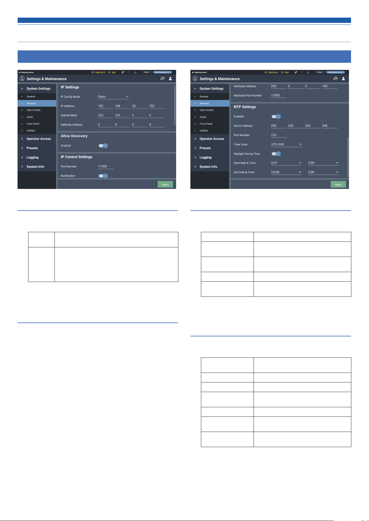
Network in System Settings
IP Settings
Set how to obtain IP addresses, and specify each value.
1. From “IP Config Mode”, select “Auto” or “Static”.
Auto IP addresses are automatically assigned from the DHCP
server, etc.
Static Specify static IP addresses.
Selecting “Static” enables the “IP Address”, “Subnet Mask”,
and “Gateway Address” fields. Enter the addresses you
want to specify.
The default value is "192.168.33.102".
2. Click “Apply”.
• The setting is now complete.
Allow Discovery
Set the product to be discovered automatically by "Locate".
1. Click the switch.
• The setting is turned ON (blue)/OFF (no color) each time the switch is
clicked.
• When the function is turned on, the product can be identified by "Locate".
2. Click “Apply”.
• The setting is now complete.
IP Control Settings
Set the options relating to IP control.
1. Set each item.
Port Number The port number of the IP control is displayed.
Notification Receive notifications from IP-controlled
Audio Level
Notification*
Multicast Address* Set the address for multicast.
Multicast Port
Number*
* This item can be set only when “Notification” is turned ON (blue).
devices.
Receive audio level notifications from
IP-controlled devices.
Set the port number for multicast.
2. Click “Apply”.
• The setting is now complete.
NTP Setting
Set the NTP (Network Time Protocol).
1. Set each item.
Enabled Set whether to enable or disable the NTP
Server Address Set the NTP server address.
Port Number Set the NTP port number.
Time Zone Set the time difference from the UTC
Daylight Saving Time Turn on/off the daylight saving time.
Start Date & Time Set the starting date/time of daylight saving
End Date & Time Set the ending date/time of daylight saving
(Network Time Protocol).
(Coordinated Universal Time).
time.
time.
2. Click “Apply”.
• The setting is now complete.
38
Page 40

Setting the system details (Settings & Maintenance)
User Access in System Settings
Login Password
Set whether or not to require a password for Administrator login.
1. Click the switch to turn on/off the setting.
• The setting is turned ON (blue)/OFF (no color) each time the switch is
clicked.
2. Enter a desired password.
• Create a password using 4 to 8 alphanumeric characters.
3. Click “Apply”.
• The setting is now complete.
Operator Page Permissions
Set whether or not to limit the devices that can be accessed by the
Operator.
1. Click the switch to turn on/off this function.
• The setting is turned ON (blue)/OFF (no color) each time the switch is
clicked.
2. Enter the IP addresses of the devices that can be accessed by
the Operator.
• Up to 5 devices can be registered.
3. Click “Apply”.
• The setting is now complete.
• No other device can be accessed by the Operator.
39
Page 41

Setting the system details (Settings & Maintenance)
Audio in System Settings
Audio System
Check/change the audio-related system settings.
1. Set each item.
Gain Unit Type Set the unit in which the gain is displayed for
adjustment.
Delay Unit Type Set the unit in which the delay time is displayed
for setting.
Output Flip Switch the output ports.
2. Click “Apply”.
• The setting is now complete.
"Output Flip"
Output of each channel assigned to an output bus is as described below.
• If “Output Flip” is turned OFF
• If “Output Flip” is turned ON
• When "Output flip" is set to ON, "OUTPUT ST" on the audio
output screen changes to "OUTPUT L/R".
40
Page 42

Setting the system details (Settings & Maintenance)
Front Panel in System Settings
Levels
Set whether or not to enable input/output level adjustment for each
channel on the front panel of the product.
1. Select/unselect the check box for each channel.
• You can adjust the level of each selected channel.
2. Click “Apply”.
• The setting is now complete.
Front Panel Restrictions
Set the operation restrictions on the front panel of the product.
1. Set each item.
Recall Preset Set whether or not to enable preset recall on
Entering Advanced
Mode
the front panel of the product.
Set whether or not to enable accessing the
advanced mode on the front panel of the
product.
2. Click “Apply”.
• The setting is now complete.
LED Dimmer
Set whether or not to enable dimming of the LEDs (dimmed illumination)
on the front panel of the product.
1. Click the switch to turn on/off the setting.
• The setting is turned ON (blue)/OFF (no color) each time the switch is
clicked.
2. Click “Apply”.
• The setting is now complete.
41
Page 43

Setting the system details (Settings & Maintenance)
Utilities in System Settings
Firmware Update
Update the firmware of the product.
1. Check “Serial No.”, “Device Name”, and “Firmware Version” on
the screen to see if this product is due for update.
2. Click “Browse”.
• The file selection screen appears.
3. Select and open the file of the latest version on the file
selection screen.
4. Click “Update”.
• Update is started. When the update is complete, the completion screen
appears.
5. Turn off the product, and then restart the product.
• After the restart, reload the page in a web browser.
Language Pack Install
Install the language pack to allow Web Remote to be displayed in
multiple languages.
1. Click “Browse”.
• The file selection screen appears.
2. Select and open the files of the desired languages on the file
selection screen.
3. Click “Install”.
• Installation is started. When the installation is complete, the completion
screen appears and you are automatically logged out.
Reset All Settings to Default
Reset the product to the factory defaults. (The firmware will remain the
current version.)
1. Click “Reset”.
• The confirmation screen appears.
2. Check the information on the confirmation screen, and click
“YES”.
• When the initialization is complete, the completion screen appears. Turn off
the product.
42
Page 44
Setting the system details (Settings & Maintenance)
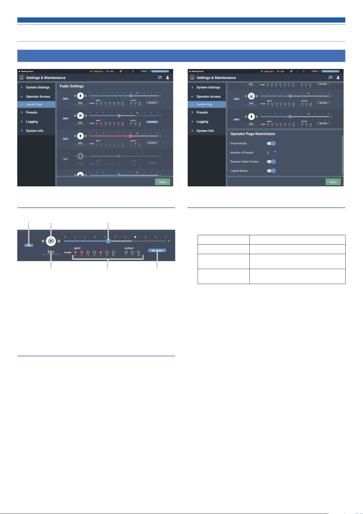
Operator Page in Operator Access
How to view the Fader Settings screen
❸❶ ❷
❹ ❺ ❻
Set whether or not to show this screen on the Operator Page.
❶
Select the icon to be displayed on the Operator Page.
❷
Adjust the volume.
❸
Set a desired name.
❹
Assign audio input to each channel.
❺
Set the maximum value of volume.
❻
Fader Settings
Check/change the operations that can be performed on the Operator
page.
1. Set each item.
• Set each item by referring to “How to view the Fader Settings screen”.
2. Click “Apply”.
• The setting is now complete.
Operator Page Restrictions
Set restrictions on the operations that can be performed on the Operator
page.
1. Set each item.
Preset Recall Set whether or not to recall presets.
Num of Presets* Set the number of presets that can be recalled.
Resume Fader Position Set whether or not to enable position resume
for up to eight fader channels.
Logout Button Set whether or not to display the Log Out
button on the screen.
* This item can be set when “Preset1.3 Recall” is turned on.
2. Click “Apply”.
• The setting is now complete.
43
Page 45
Setting the system details (Settings & Maintenance)
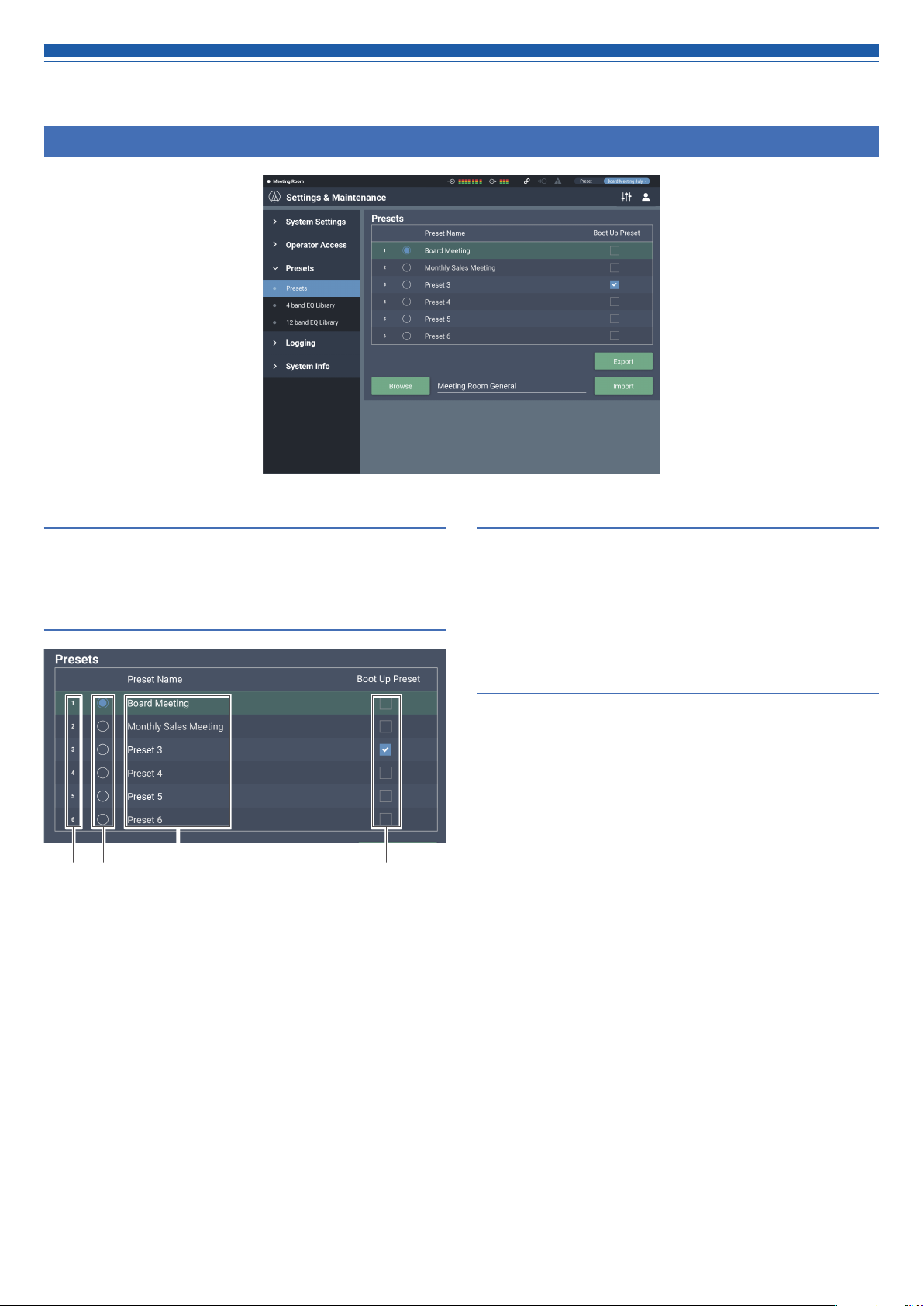
Presets in Presets
Presets
Check/change the preset settings currently registered in the product,
and import/export preset files.
How to view the Presets screen
❸❶ ❷ ❹
Preset number
❶
Radio button
❷
Select a preset.
Preset name
❸
Set a desired name.
Boot up preset
❹
Each time this product is started, the selected preset is recalled.
Exporting a preset
1. Click the radio button corresponding to the preset number from
which you want to export.
• Clicking the button selects the preset (the color turns to blue).
2. Click “Export”.
3. Set the save location/file name, and export the file.
Importing a preset
A preset created elsewhere can be imported.
1. Click the radio button corresponding to the preset number to
which you want to import.
• Clicking the button selects the preset (the color turns to blue).
2. Click “Browse”, and select the external file.
3. Click “Import”.
• The preset is imported.
44
Page 46

Setting the system details (Settings & Maintenance)
4 Band EQ Library in Presets
4 Band EQ Library
You can import/export 4-band EQ patterns to be applied to audio inputs
as a preset.
EQ Preset A setting in which the EQ patterns for all
bands are saved.
Library A group that includes all presets.
Changing a preset name
1. Click the preset name you want to change.
2. Enter the new preset name.
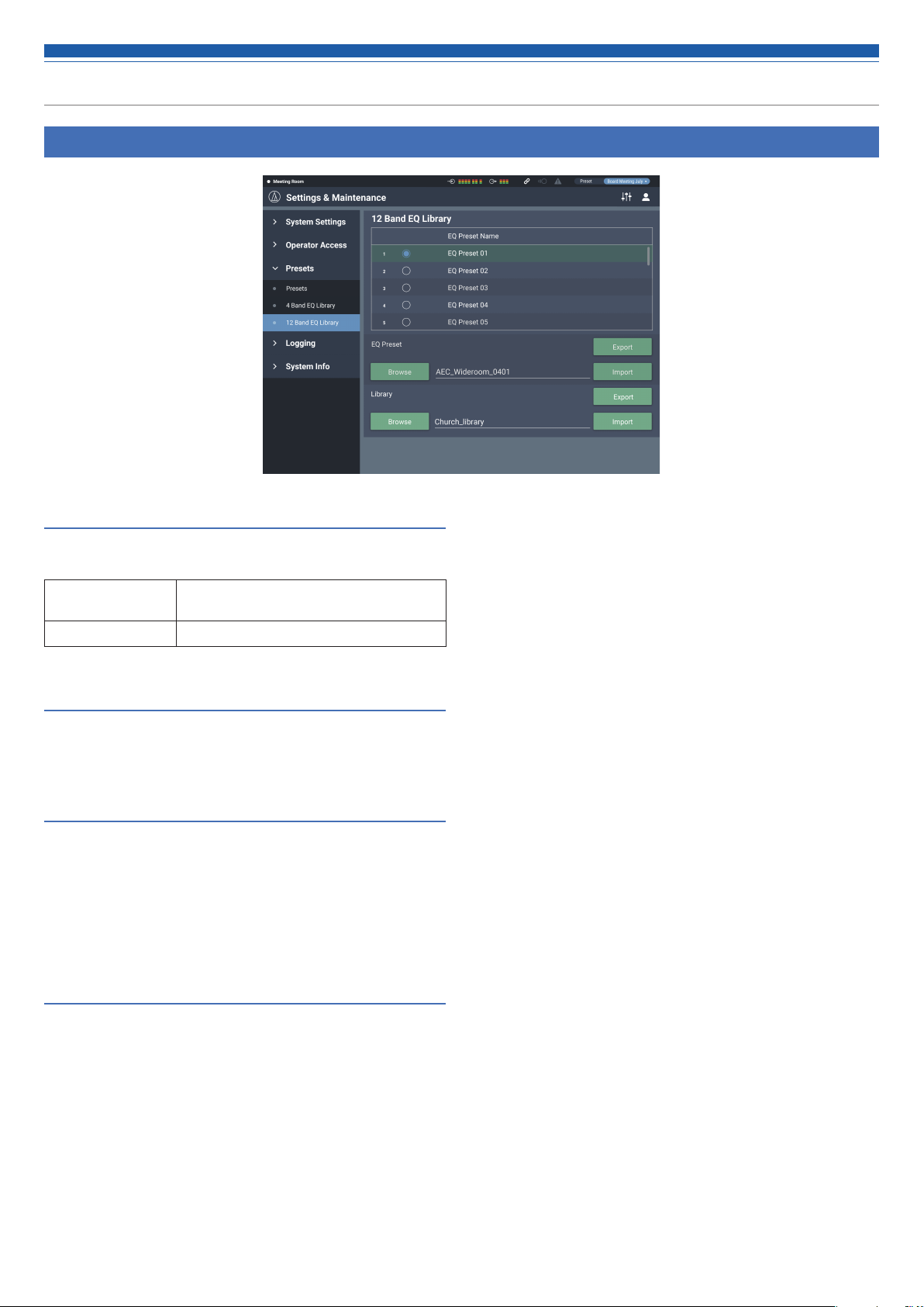
Exporting a preset/library
1. Click the radio button corresponding to the preset number from
which you want to export.
• Clicking the button selects the preset (the color turns to blue).
• When exporting a library, you need not select all applicable presets.
2. Click “Export” from “EQ Preset”/”Library”.
3. Set the save location/file name, and export the file.
Importing a preset/library
1. Click the radio button corresponding to the preset number to
which you want to import.
• Clicking the button selects the preset (the color turns to blue).
• When importing a library, you need not select all applicable presets.
2. Click “Browse” from “EQ Preset”/”Library” and select the
external file.
3. Click “Import” from “EQ Preset”/”Library”.
• The preset/library is imported.
45
Page 47
Setting the system details (Settings & Maintenance)
12 Band EQ Library in Presets
12 Band EQ Library
You can import/export 12-band EQ patterns to be applied to audio
outputs as a preset.
EQ Preset A setting in which the EQ patterns for all
bands are saved.
Library A group that includes all presets.
Changing a preset name
1. Click the preset name you want to change.
2. Enter the new preset name.
Exporting a preset/library
1. Click the radio button corresponding to the preset number from
which you want to export.
• Clicking the button selects the preset (the color turns to blue).
• When exporting a library, you need not select all applicable presets.
2. Click “Export” from “EQ Preset”/”Library”.
3. Set the save location/file name, and export the file.
Importing a preset/library
1. Click the radio button corresponding to the preset number to
which you want to import.
• Clicking the button selects the preset (the color turns to blue).
• When importing a library, you need not select all applicable presets.
2. Click “Browse” from “EQ Preset”/”Library” and select the
external file.
3. Click “Import” from “EQ Preset”/”Library”.
• The preset/library is imported.
46
Page 48

Setting the system details (Settings & Maintenance)
Logging in Logging
Logging
Set the options relating to log messages, and download log files.
Enabled Set whether or not to save log messages.
Destination Set whether to write log messages to the
internal memory or transfer them to the
Syslog server.
Log File You can download the log file recorded to the
internal memory by clicking “Download”.
After setting each item, click “Apply” to complete the setting.
• Syslog is a standard for transferring log messages across IP
networks. It is used for administration of computer systems
and security monitoring.
47
Page 49

Setting the system details (Settings & Maintenance)
System Info in System Info
System Info
System information, such as the various network settings and the
product's serial number and firmware version, is displayed.
48
Page 50

Key functions
AEC (Acoustic Echo Canceler)
In meetings held between remote locations, such as teleconferencing, acoustic echoes can occur when the audio output from the speaker is picked
up by a microphone. The audio from the other party is amplified by the speaker and can bounce off of the ceiling, walls or floors of the room, and,
upon being picked up by the microphone, is returned to the other party along with your party’s audio. The other party hears the delayed own audio,
making it difficult to speak back.
Using the other party’s signals as reference signals, the acoustic echo canceler removes only the echoes in the other party's audio from the audio
signals sent from your party. This makes it possible to deliver clear audio, with no echoes, to the other party.
Your party Other party
AEC
49
Page 51

Key functions
Setting AEC
1. Click “AEC”.
2. From “Mode”, select “AEC”.
4. Turn AEC ON for the Mic to be used (for each channel).
5. From “Output Bus”, select the signal (output bus) to be returned
to the other party.
3. From “AEC Reference”, select the reference signal (the signal for
removing echoes).
• In general, a signal from the other party is set as the reference signal.
6. Click ”AEC Calibration”.
• The confirmation screen appears.
50
Page 52

Key functions
7. Click “Start”.
• Reverberation measurement begins.
• Click ”Test” to play the test audio for a check. Click it again to stop playing
the test audio.
• If no operation is performed for some time or so, the error screen appears.
Click ”OK” to return to the previous screen. Repeat the procedure.
8. After the reverberation setting, confirm that the ERL meter
fluctuates.
• Perform the following procedures as necessary.
10. If necessary, turn ON “NLP”.
• These features may increase the echo canceling effect.
Saving the AEC adaptive filter setting
1. Click “Apply”.
• Save the AEC adaptive filter setting.
• To save the AEC adaptive filter status also when saving a preset, click
“Apply”, and then save the preset.
9. Adjust the “Reference Level” until the ERL meter is at 10 or
above.
51
Page 53

Key functions
SmartMixer
The SmartMixer function is designed to automatically adjust the audio
input and output of the microphone channel without picking up any
unnecessary noise or allowing howling to occur in meetings where an
unspecified large number of participants speak at the same time. It is
particularly effective in meetings, such as a panel discussion, where the
participants can speak at any given time. The automation of the otherwise
cumbersome fader operation by an operator makes it possible to have
stable and efficient operation. SmartMixer can be either “gate mode” or
“gain sharing mode”.
Gate mode SmartMixer
When there is an audio input to a microphone, the corresponding
channel automatically opens. If more than one microphone receives
audio input, the audio inputs to all open channels are added. Simply
adding the audio inputs tends to lower the howling margin, thereby
reducing the audio quality. To address this issue, the gate mode
SmartMixer attenuates the added audio inputs based on the number of
open mic channels.
Gain sharing mode SmartMixer
2. From “Mode”, select “Gate”.
3. Click “Enabled” for each channel that should operate with the
SmartMixer function.
• It turns ON (purple) when clicked.
This type of SmartMixer compares the audio input level of each mic
channel against the total sum of the audio input levels from all open
mic channels, and, based on the ratio, divides the gain among all the
channels. With this, the total gain always (remains constant), whether
the audio input is from one microphone or multiple microphones.
Setting Gate mode SmartMixer
Configure all settings using Web Remote.
1. Click “Smart Mix”.
52
Page 54

Key functions
4. Set “Priority”, “Can Cut”, and “Off Attenuation” for each channel,
as necessary.
Priority When this is set to ON, the gate of this
microphone input channel opens first over the
other channels whose “Priority” is OFF.
• Depending on the setting of the priority
mode, the gate may not open.
Can Cut When this is set to ON for a channel whose
“Priority” is ON, the gates of the other
channels whose “Priority” is OFF close upon
opening of the gate of this microphone input
channel.
OFF Attenuation Set the attenuation level when the gate of the
microphone input channel is closed.
6. Set “Last Mic On”, “Gate Hold time”, “NOMA”, and “Num of Open
Mics”.
Last Mic ON When this is set to ON, the last opened
microphone input channel gate remains open.
Gate Hold Time Set the time after the audio input is ceased
until the microphone input channel gate is
closed.
NOMA This function is used to attenuate the output
according to the number of open microphone
input channel gates. It is recommended that
“NOMA” be set to ON to prevent howling.
Num of Open
Mics
Priority Mode Either mode of the following applies when the
Limit the number of microphone input channel
gates that open simultaneously. Change this
value according to the operating method.
number of microphone input channel gates
that currently open reaches the “Num of Open
Mics”.
Mode 1: Channels cannot be opened even if
their "Priority" is ON.
Mode 2: Channels can be opened if their
"Priority" is ON.
5. Assign signals to the output buses.
53
Page 55

Key functions
Setting gain sharing mode SmartMixer
Configure all settings using Web Remote.
1. Click “Smart Mix”.
2. From “Mode”, select “Gain Share”.
4. Set “Weight” for each channel, as necessary.
• The gain to be distributed can be adjusted. This can be used also to balance
the background noise for each channel.
5. Assign signals to the output buses.
3. Click “Enabled” for each channel that should operate with the
SmartMixer function.
• It turns ON (purple) when clicked.
6. Monitor the gain meter of each channel to confirm that the total gain is
distributed based on the input signals.
54
Page 56
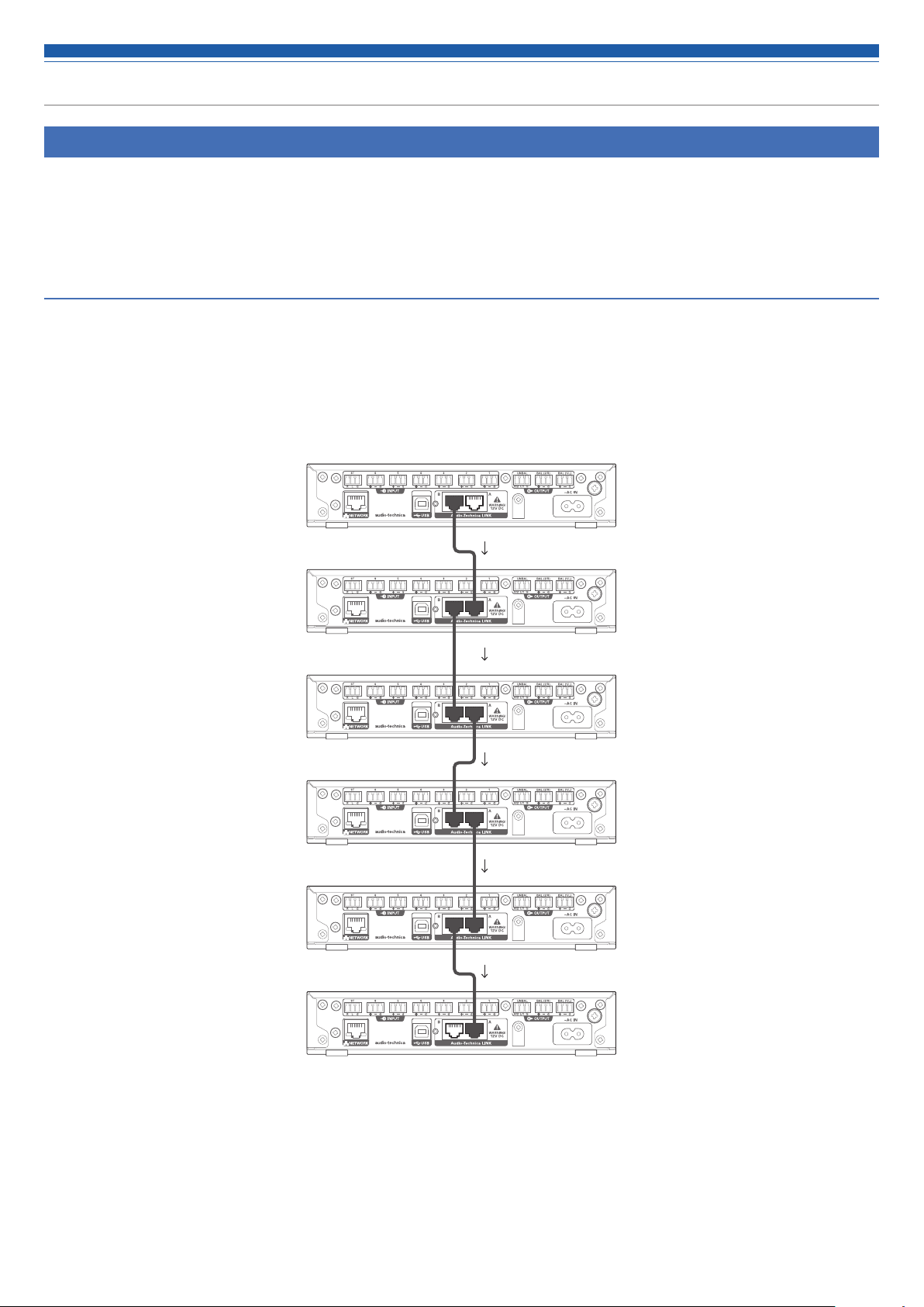
Key functions
Audio-Technica LINK
Up to six ATDM-0604 model mixers can be daisy-chained so that, as a whole system, it can handle audio inputs from 24 Mic channels, 12 Mic/Line
channels, and 6 unbalanced stereo channels. The proprietary Audio-Technica LINK functionality enables the transmission of low-latency, high-speed
audio bus signals between devices, making it possible to steadily control and transmit uncompressed audio signals. Furthermore, the model offers
excellent workability as it conforms to the Ethernet standards and can be connected to generic LAN cables (shielded cables of Cat5e or above with
the conductor diameter size of 24 AWG or larger are recommended).
Connection and setting procedures
1. Daisy-chain the ATDM-0604 devices (up to six).
• The LINK terminal can be LINK A or LINK B. There is no distinction — and the polarity is not specific — between the two. Therefore, they can be connected in any
combination : A to B, B to A, A to A, or B to B. Taking ease of maintenance after the installation into account, however, it is recommended that the terminals be
connected in the same pattern within the same system.
• Do not connect the devices in a ring pattern. Make sure to leave one of the two LINK terminals at both ends of the daisy-chained ATDM-0604 devices
unconnected.
• For connections, use a LAN cable of Cat5e or above with conductor diameter size of 24 AWG or larger (shielded cables are recommended).
Connection example
Primary
B
Extension
A
Extension
Extension
Extension
Extension
B
B
A
B
A
A
B
A
2. Launch Web Remote, and configure the settings related to the Audio-Technica LINK for each ATDM-0604.
55
Page 57

Key functions
1. In “Audio-Technica LINK Mode”, set the ATDM-0604 connected to one of the two ends as “Primary”.
• Do not set any of ATMD-0604 devices connected in the middle as “Primary”. The connection will not be recognized properly.
2. Set all other ATDM-0604 devices as “Extension”.
• Do not set more than one ATDM-0604 as “Primary”.
56
Page 58

Key functions
ST
UNBAL
ST
UNBAL
UNBAL
ST1/L 2/R
ST
Sharing audio buses
In “Audio-Technica LINK”, the audio output buses (Output 1/L, Output 2/R, and Output ST) and the AEC reference signal bus are shared among the
ATDM-0604 devices.
With this, any ATDM-0604 can output audio inputs from 24 Mic channels, 12 Mic/Line channels, and 6 unbalanced stereo channels. The AEC
reference signals can also be shared among the devices.
AEC
Ref.
Primary
1
6
Extension (Device 1)
1
6
ST
2/R
1/L
AEC Ref.
ST
2/R
1/L
AEC Ref.
2/R
1/L
2/R
1/L
Extension (Device 5)
1
6
ST
2/R
1/L
AEC Ref.
2/R
1/L
57
Page 59

Key functions
Front panel operation restriction
The following two modes are available when operating the product with
the buttons and the dial on the front panel.
Operator mode:
In this mode, daily operations are performed, such as loading the preset settings
and adjusting the audio level.
Advanced mode:
In this mode, advanced settings can be configured by installing and implementing
the product on-site.
When the power is turned on, the product usually starts in operator
mode. This prevents accidental device setting changes or other troubles,
and ensures a safe operation of the system.
This section explains how to restrict the front panel operation using Web
Remote.
• The restriction cannot be activated in Advanced mode.
1. Select “Administrator”, enter the password and click “Login”.
• If you are logged in as an operator, log out, and then log back in.
3. Click “Front Panel”.
4. In the “Levels” setting, set the operation restriction for the
audio level adjustment.
• If INPUT and OUTPUT for each channel are selected, the audio level for that
channel can be adjusted.
• Clear the check boxes not to allow these controls.
2. Click the icon ( ) on the top right of the screen.
5. In the “Front Panel Restrictions” settings, configure the front
panel operation restriction settings.
• The setting is turned ON (blue)/OFF (no color) each time the switch is
clicked.
Enable
Preset
Recall
Enable
Advanced
Mode
Set whether or not to enable preset recall on the front panel
of the product.
Specify whether or not to allow a change from operator
mode to advanced mode on the front panel of the product.
6. Click “Apply”.
• The setting is now complete.
58
Page 60

Key functions
Recalling Preset
Operator screen
1. Click the green area at the top of the screen.
2. Select the preset of your choice from the pull-down menu.
• The preset name appears, and the settings change based on the selected
preset.
Administrator screen
1. Click “Preset” at the top right of the screen.
2. Select “Recall Preset” from the pull-down menu.
3. Select the preset of your choice.
• The preset name appears, and the settings change based on the selected
preset.
59
Page 61

Key functions
About preset
The product includes preset patterns using a web or video conference.
Preset #1 (Initialization of audio settings)
• Reset the audio settings on the product to the factory defaults.
• All settings are deleted when initialized. Accordingly, it is recommended that the settings be saved to another preset or a hard disk space.
• The administrator password and IP address are not initialized. If you forget the administrator password or do not have the correct IP address to
access the product, initialize the product system. For the system initialization procedure, refer to p.42.
Preset #2 (Self-amplification)
This preset is suitable for self-amplification in a small- to mid-size conference room. It can also be used when amplification of the instructor with a
speaker is necessary in a remote lecture or seminar. The product is equipped with a feedback suppressor for each output system to control howling.
It is also equipped with a noise canceler that can reduce the fan noise generated by an air conditioning system or a projector and collect and amplify
comfortable audio.
Ceiling speaker
Tablet / Smartphone
Web Remote
for operator
Router
AP
Switching hub
Near-end source
Mic
Balanced audio cable
Power amplifier
Main speaker
Power amplifier
Balanced audio cable
Balanced audio cable
AC power cableEthernet cable
AC power
60
Page 62
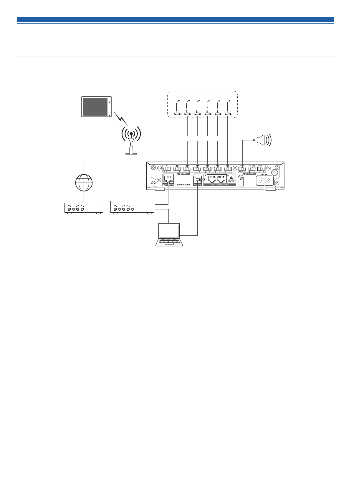
Key functions
Preset #3 (Web conference)
This preset is suitable for web conferencing using software codecs. The product, equipped with a USB audio interface, is capable of handling meetings
held at any location using a computer or tablet with an Internet connection. It is also equipped with an echo canceler to provide quality conferencing
with no echoes or dropouts.
Tablet / Smartphone
Web Remote
for operator
Far-end source
Internet
Near-end source
Mic
AP
Balanced audio cable
cable
Switching hubRouter
Computer
Powered speaker
Unbalanced audio cable
AC power cableUSB cable Ethernet
AC power
61
Page 63

Key functions
Preset #4 (Video conference)
This preset is suitable for video conferencing using hardware codecs. The unbalanced output on this product is compatible with both Mic and Line
levels, and the output level setting can be changed according to the input level of the video conference system being used. It is also equipped with
an echo canceler to provide quality conferencing with no echoes or dropouts.
Tablet / Smartphone
Web Remote
for operator
Far-end source
AP
Internet
Far-end source
Video conference
system
Ceiling speaker
Near-end source
Mic
Balanced audio cable
Unbalanced audio cable
Power amplifier
Unbalanced audio cable
Balanced audio cable
AC power cableEthernet cable
AC power
Switching hubRouter
62
Page 64

Key functions
Copying settings
The settings for a channel can be copied to another channel.
1. Click the icon (
2. Click “Copy”.
) of the source channel.
3. Select the a different source channel.
• To select another channel, click the channel selected. The selection of the
channel is canceled. Reselect the channel to copy.
4. Select the target channel.
• To select a different channel, click the channel selected. The selection of
the channel is canceled. Reselect the target channel.
5. Click “Paste”.
• To cancel the copying, click “Cancel”. The screen returns to the previous
screen.
63
Page 65

Key functions
Resetting settings
The settings for a channel can be reset to the default settings.
1. Click the icon (
) of the channel to reset.
2. Click “Reset”.
64
Page 66
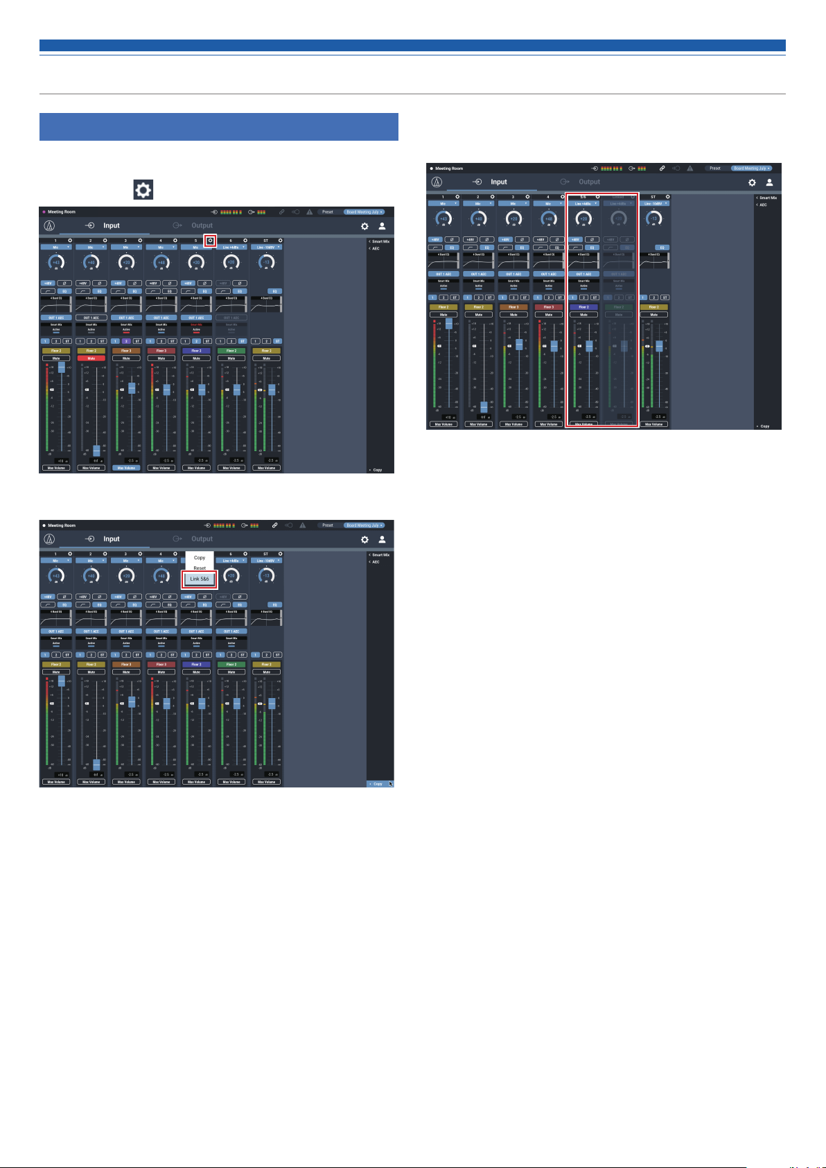
Key functions
Linking channels
Link channels to share the settings. You can link only input channels 5
and 6.
1. Click the icon (
2. Click “Link 5&6”.
) of the channels to be linked.
3. Confirm that the input channels have been linked.
• The settings of the channel 6 are same as the settings of the channel 5.
• The linked channel 6 are grayed out and cannot be used.
65
Page 67
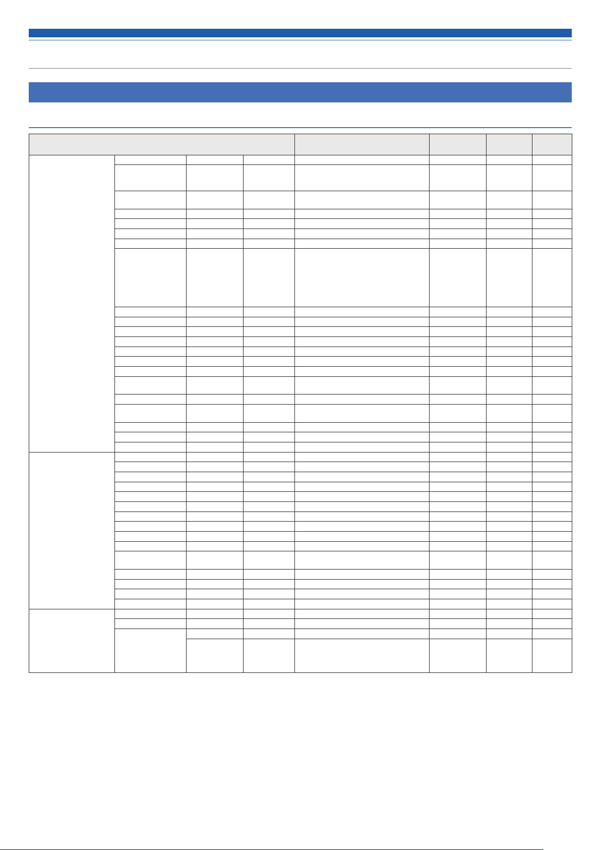
Menu Item
Audio Settings
Input
Item name Setting values Default Setting
Input channel 1 to 6 CH # CH 1 to 6 - - -
Mode Select*
1
Ch1 to 4: Mic
Mic
Ch5, 6: Mic, Line 0dBV, Line +4dBu,
Presets
Included
✓ ✓
Resumed
Line -10dBV, Line -20dBV
Input gain +20dB to +60dB
-20dBu to -60dBu
+20
✓ ✓
Phantom On, Off Off ✓ Phase On, Off Off ✓ ✓
Lowcut On, Off Off ✓ ✓
4 Band EQ On, Off Off ✓ ✓
OUT 1 AEC
OUT 2 AEC
OUT ST AEC*
OUT 1 NC*
OUT 2 NC*
OUT ST NC*
2
2
2
2
On, Off Off
✓ ✓
Smart Mix Disable, Enable, Priority, Mixing Disable - Output 1 Bus On, Off Off ✓ ✓
Output 2 Bus On, Off Off ✓ ✓
Output ST Bus*
3
On, Off Off ✓ ✓
Level meter 60Point + Pk. - - Level -∞, -120dB to +10dB -∞ ✓ ✓
CH Name (Maximum 10 byte) CH 1 to 6 ✓ ✓
CH Color Green, Yellow, Brown, Red, Pink, Blue,
Gray, Dark Gray
Green
✓ ✓
CH mute On, Off Off ✓ ✓
Link 5&6
(CH 5, 6 only)
Unlink 5&6, Link 5&6 Unlink 5&6
✓ ✓
Max Volume On, Off Off ✓ ✓
Copy - - - Reset - - - -
Input channel ST CH # ST - - -
Mode Select Line -10dBV, Line -20dBV, USB Line -10dBV ✓ ✓
Input gain -20dB to +20dB 0 ✓ ✓
4 Band EQ On, Off Off ✓ ✓
Output 1 Bus On, Off Off ✓ ✓
Output 2 Bus On, Off Off ✓ ✓
Output ST Bus*
3
On, Off Off ✓ ✓
Level meter 60Point + Pk. - - Level -∞, -120dB to +10dB -∞ ✓ ✓
CH Name (Maximum 10 byte) AUX ✓ ✓
CH Color Green, Yellow, Brown, Red, Pink, Blue,
Gray, Dark Gray
Green
✓ ✓
CH mute On, Off Off - ✓
Max Volume On, Off Off ✓ ✓
Copy - - - Reset - - - -
4 Band EQ Mode change Easy mode⇄Expert mode Expert mode - ✓
Recall EQ Preset
- - ✓ ✓
Easy mode Type Select High , Mid , Low Mid ✓ ✓
Tone Warm, Warm-1, Warm-2, Warm-3, Warm-
4, Warm-5, Warm-6, Natural, Bright-6,
Bright-5, Bright-4, Bright-3, Bright-2,
Natural
✓ ✓
Bright-1, Bright
66
Page 68

Menu Item
Item name Setting values Default Setting
4 Band EQ Expert mode Band #1 Gain -18dB to +18dB 0 ✓ ✓
Reset - - - -
Smart Mix mode Enable On, Off Off ✓ ✓
Gain Share Gain Share Meter 0 to -15 - - -
Weight -15 to 15 0 ✓ ✓
Gate Priority On, Off Off ✓ ✓
Can Cut On, Off O ff ✓ ✓
Off Attenuation -60db to 0dB -40 ✓ ✓
Band #1
Frequency
Band #1 Q
value
Band #1 Filter
type
Band #2 Gain -18dB to +18dB 0 ✓ ✓
Band #2
Frequency
Band #2 Q
value
Band #3 Gain -18dB to +18dB 0 ✓ ✓
Band #3
Frequency
Band #3 Q
value
Band #4 Gain -18dB to +18dB 0 ✓ ✓
Band #4
Frequency
Band #4 Q
value
Band #4 Filter
type
20Hz to 20kHz 25
0.3 to 60 0.75
HPF, LSH, PEQ PEQ
20Hz to 20kHz 63
0.3 to 60 0.75
20Hz to 20kHz 6.3k
0.3 to 60 0.75
20Hz to 20kHz 16k
0.3 to 60 0.75
LPF, HSH, PEQ PEQ
Presets
Included
✓ ✓
✓ ✓
✓ ✓
✓ ✓
✓ ✓
✓ ✓
✓ ✓
✓ ✓
✓ ✓
✓ ✓
Resumed
*1 "Mic" cannot be selected when selecting "Link 5&6".
*2 When "Mode" in "AEC" is set to "NC", the screen changes to "Output L/R NC".
*3 When "Mode" in "AEC" is set to "NC", the screen changes to "Output L/R Bus".
Smart Mix
Item name Setting values Default Setting
Smart Mix Mode Off, Gate, Gain Share Gain Share ✓ ✓
Last Mic On On, Off Off ✓ ✓
Hold Time 0.5 to 10.0 seconds 2.5 ✓ ✓
NOMA On, Off Off ✓ ✓
Num of Open Mics
Priority Mode Mode1, Mode2 Mode1 ✓ ✓
1 to 6 6 ✓ ✓
Presets
Included
Resumed
AEC
Item name Setting values Default Setting
AEC Mode Off, AEC , NC AEC ✓ ✓
Output Bus 1, 2, ST* 1 ✓ ✓
AEC Reference OUT1, OUT2, OUT ST*
Send Reference for
External
Advanced Settings AEC Sensitivity Low, High Low
NC Attenuation
Level
NLP On, Off On ✓ ✓
NLP Sensitivity Low, High Low ✓ ✓
Reference Level -60dB to +10dB 0 ✓ ✓
ERL Meter 60 Point. -
ERLE Meter 60 Point. - - TER Meter 60 Point. - - Reference Level
Meter
AEC Calibration - - - -
IN 1 to 6, AUX, External
On, Off O ff
0dB to 20dB 10
60 Point. -
OUT1
Presets
Included
✓ ✓
✓ ✓
✓ ✓
- -
- -
Resumed
* When "Output Flip" is set to ON, the screen changes to "L/R".
67
Page 69

Menu Item
Output
Item name Setting values Default Setting
CH Name (Maximum 30 characters (ASCII code
Unity
(Output 1/2)
Unity
(Output ST)
Level -∞, -120dB to +10dB -40dB - Level meter 60 Point + Pk. - - FBS On, Off O ff ✓ ✓
EQ On, Off O ff ✓ ✓
Dynamics On, Off Off ✓ ✓
Delay Enabled On, Off Off ✓ ✓
Delay settings
Max Volume On, Off O ff ✓ ✓
Copy - - - Reset - - - -
only))
+4dBU, 0dBV, -10dBV +4dBu
-33dBV,-10dBV -10dBV
0ms to 1000ms, 0.34M to 340.00M,
to 1115.20Ft
1.12Ft
OUT 1, OUT 2
0ms,
0.34M,1.12Ft
Presets
Included
- -
✓ ✓
✓ ✓
✓ ✓
Resumed
USB OUT
Item name Setting values Default Setting
USB Out Bus Select OUT 1 On, Off Off ✓ ✓
OUT 2 On, Off Off ✓ ✓
OUT ST* On, Off Off
AEC OUT On, Off Off ✓ ✓
Send Level -∞, -120dB to 0dB 0 ✓ ✓
Presets
Included
✓ ✓
Resumed
* When "Output Flip" is set to ON, the screen changes to "Output L/R".
CH Detail Setting in Output
Item name Setting values Default Setting
Feedback Suppressor
Setting
12 Band EQ Setting Output 1,2,ST Band #1 Enable On ,Off On ✓ ✓
Output 1,2,ST Band #1 to 8 Current
Reset - - - -
Copy to 12
FBS common
settings
Band EQ
Detection Low, Mid, High High
Response Slow, Fast Fast ✓ ✓
Band #1 Gain -18dB to +18dB 0 ✓ ✓
Band #1
Frequency
Band #1 Q
value
Band #1 Filter
type
Band #2 Enable On, Off On ✓ ✓
Band #2 Gain -18dB to +18dB 0 ✓ ✓
Band #2
Frequency
Band #2 Q
value
Band #3 Enable On, Off On ✓ ✓
Band #3 Gain -18dB to +18dB 0 ✓ ✓
Band #3
Frequency
Band #3 Q
value
Band #4 Enable On, Off On ✓ ✓
Band #4 Gain -18dB to +18dB 0 ✓ ✓
Band #4
Frequency
Band #4 Q
value
frequency
Band switch On, Off Off ✓ ✓
- -
- -
20Hz to 20kHz 20
0.3 to 60 0.75
HPF, LSH, PEQ PEQ
20Hz to 20kHz 30
0.3 to 60 0.75
20Hz to 20kHz 60
0.3 to 60 0.75
20Hz to 20kHz 120
0.3 to 60 0.75
Presets
Included
- -
- -
✓ ✓
✓ ✓
✓ ✓
✓ ✓
✓ ✓
✓ ✓
✓ ✓
✓ ✓
✓ ✓
✓ ✓
Resumed
68
Page 70

Menu Item
CH Detail Setting in Output
Item name Setting values Default Setting
12 Band EQ Setting Output 1,2,ST Band #5 Enable On, Off On ✓ ✓
Dynamics Setting Output 1,2,ST Input Level - - - -
Band #5 Gain -18dB to +18dB 0 ✓ ✓
Band #5
Frequency
Band #5 Q
value
Band #6 Enable On, Off On ✓ ✓
Band #6 Gain -18dB to +18dB 0 ✓ ✓
Band #6
Frequency
Band #6 Q
value
Band #7 Enable On, Off On ✓ ✓
Band #7 Gain -18dB to +18dB 0 ✓ ✓
Band #7
Frequency
Band #7 Q
value
Band #8 Q
value
Band #9 Enable On, Off On ✓ ✓
Band #9 Gain -18dB to +18dB 0 ✓ ✓
Band #9
Frequency
Band #9 Q
value
Band #10
Enable
Band #10 Gain -18dB to +18dB 0 ✓ ✓
Band #10
Frequency
Band #10 Q
value
Band #11
Enable
Band #11 Gain -18dB to +18dB 0 ✓ ✓
Band #11
Frequency
Band #11 Q
value
Band #12
Enable
Band #12 Gain -18dB to +18dB 0 ✓ ✓
Band #12
Frequency
Band #12 Q
value
Band #12 Filter
type
Flat - - - -
Recall Library - - ✓ ✓
Save Library - - ✓ ✓
Reset all band - - - -
Gain Reduction - - - -
Output Level - - - -
Compressor
Ratio
Compressor
Threshold
Compressor
Att ack
Compressor
Release
Output Gain +10dB to -10dB 0 ✓ ✓
Limiter
Threshold
20Hz to 20kHz 240
0.3 to 60 0.75
20Hz to 20kHz 500
0.3 to 60 0.75
20Hz to 20kHz 1k
0.3 to 60 0.75
0.3 to 60 0.75
20Hz to 20kHz 4k
0.3 to 60 0.75
On, Off On
20Hz to 20kHz 8000
0.3 to 60 0.75
On, Off On
20Hz to 20kHz 1.6k
0.3 to 60 0.75
On, Off On
20Hz to 20kHz 20k
0.3 to 60 0.75
LPF, HSH, PEQ PEQ
1:1.4, 1:2, 1:4, 1:6, 1:10, 1:∞ 1:2
-60dB to 0dB -10
0msec, 0.25msec, 0.5msec, 1msec,
2msec, 4msec, 8msec, 16msec,
32msec, 100msec
50msec, 100msec, 200msec,
400msec, 800msec, 1000msec,
2000msec
-60 to 0dB 0
1msec
400msec
Presets
Included
✓ ✓
✓ ✓
✓ ✓
✓ ✓
✓ ✓
✓ ✓
✓ ✓
✓ ✓
✓ ✓
✓ ✓
✓ ✓
✓ ✓
✓ ✓
✓ ✓
✓ ✓
✓ ✓
✓ ✓
✓ ✓
✓ ✓
✓ ✓
✓ ✓
✓ ✓
✓ ✓
✓ ✓
Resumed
69
Page 71
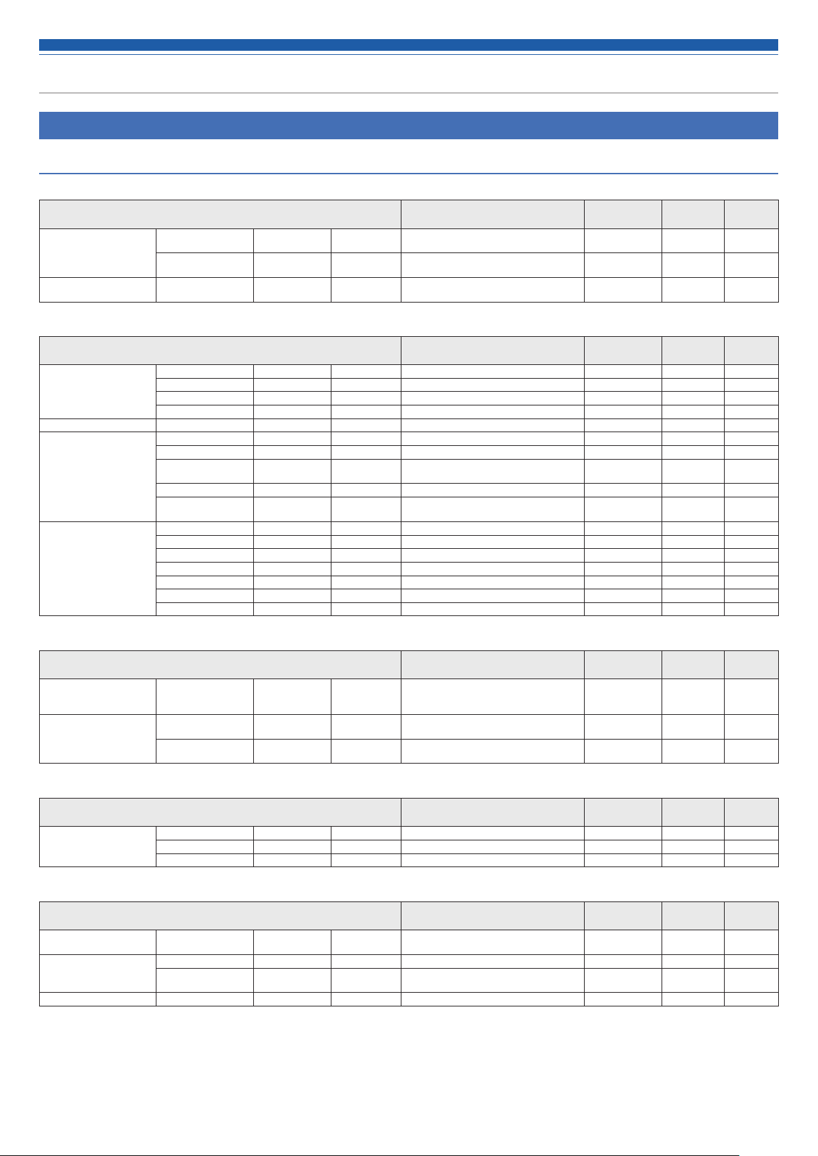
Menu Item
Settings & Maintenance
System Settings
General
Item name Setting values Default Setting
Device Name Device Name (Maximum 30 characters (ASCII code
Header Color White, Green, Yellow, Orange, Purple,
Audio-Technica LINK
Mode
Audio-Technica LINK
Mode
only))
Cyan
Primary, Extension Primary - ✓
ATDM-0604 - ✓
White - ✓
Network
Item name Setting values Default Setting
IP Setting IP Config Mode Auto, Static Auto - ✓
Allow Discovery Enabled On, Off On - ✓
IP Control Setting Port Number 00001 to 65535 17300 - ✓
NTP Setting Enabled On, Off Off - ✓
IP Address 0.0.0.0 to 255.255.255.255 - - ✓
Subnet Mask 0.0.0.0 to 255.255.255.255 - - ✓
Gateway Address 0.0.0.0 to 255.255.255.255 - - ✓
Notification On, Off On - ✓
Audio Level
Notification
Multicast Address
Multicast Port
Number
Server Address 0.0.0.0 to 255.255.255.255 - - ✓
Port Number 00001 to 65535 123 - ✓
Time Zone UTC -12:00 to +14:00 00:00 - ✓
Daylight Saving Time On, Off Off - ✓
Start Date & Time 1/1 to 12/31, 0:00 to 23:00 3/27, 2:00 - ✓
End Date & Time 1/1 to 12/31, 0:00 to 23:00 10/30, 2:00 - ✓
On, Off On - ✓
0.0.0.0 to 255.255.255.255 225.0.0.100 - ✓
00001 to 65535 17000 - ✓
Presets
Included
Presets
Included
Resumed
Resumed
User Access
Item name Setting values Default Setting
Login Password Administrator
Operator Page
Permissions
Password
Restrict Access On, Off Off
Permission IP1 to
IP5
On, Off
(Minimum 4, Maximum 8 characters
(alphabet and number only))
0.0.0.0 to 255.255.255.255 -
Off
Presets
Included
- ✓
- ✓
- ✓
Resumed
Audio
Item name Setting values Default Setting
Audio System Gain Unit Type dBu/dBV, dB dB - -
Delay Unit Type ms, M, Ft ms - Output Flip On, Off Off - -
Presets
Included
Resumed
Front Panel
Item name Setting values Default Setting
Levels INPUT: 1 to 6CH, ST
Front Panel Restrictions
LED Dimmer LED Dimmer On, Off Off - ✓
OUTPUT: 1, 2, ST
Enable Preset Recall
Enable
Advanced
Mode
Enable, Disable Enable - ✓
Enable, Disable Enable - ✓
Enable, Disable Enable - ✓
Presets
Included
Resumed
70
Page 72

Menu Item
Utilities
Item name Setting values Default Setting
Firmware Update
Launguage Pack Install - - - Reset All Settings to
Default
- - - -
- - - -
Operator Access
Operator Page
Item name Setting values Default Setting
Fader Settings Fader 1 to 8 Show On, Off Off
Operator Page
Restrictions
Name (Maximum 10 characters (ASCII code
Icon Mic, Aux, PC, Chat, Spk, Rec Mic ✓ ✓
Level 0 to 100 70 ✓ ✓
Max Volume On, Off O ff ✓ ✓
Assign INPUT: 1 to 6, ST
Preset Recall On, Off On
Number Of Presets 1 to 6 6 ✓ ✓
Resume Fader
Position
Logout Button On, Off On ✓ ✓
only))
OUTPUT: 1, 2, ST
On, Off O ff
(Fader 1: On)
Mic
Off
(INPUTl 1: On)
Presets
Included
Presets
Included
✓ ✓
✓ ✓
✓ ✓
✓ ✓
✓ ✓
Resumed
Resumed
Presets
Presets
Item name Setting values Default Setting
Presets Preset Name (Maximum 30 Byte) Preset 1 to 6 ✓ -
Boot Up Preset 1 to 6, Non Non - ✓
Presets
Included
Resumed
4 Band EQ Library
Item name Setting values Default Setting
4 Band EQ Library EQ Preset Name (Maximum 30 Byte) EQ Preset 01 to
20
Presets
Included
- ✓
Resumed
12 Band EQ Library
Item name Setting values Default Setting
12 Band EQ Library EQ Preset Name (Maximum 30 Byte) EQ Preset 01 to
20
Presets
Included
- ✓
Resumed
Logging
Logging
Item name Setting values Default Setting
Logging Enabled On, Off On - ✓
Destination Internal, Syslog Internal - ✓
Log File - - - -
Presets
Included
Resumed
System Info
System Info
Item name Setting values Default Setting
System Info - - - -
71
Presets
Included
Resumed
Page 73

Troubleshooting
If you encounter a problem, please check the following.
• Check whether all connections are correct.
• Check whether the system is being operated according to the instructions provided in the manual.
• Check whether the external devices are functioning properly. Check the devices without connecting them to the product.
• Restart the network devices.
If any of the devices in the system are not functioning properly, check the troubleshooting tips below.
If none of the tips apply, please contact your local Audio-Technica dealer.
You may be asked to provide the version of your firmware. Please check in advance and have the firmware version handy.
To find the firmware version on the product: Refer to p.17.
To find the firmware version via Web Remote: Refer to p.42.
ATDM-0604 unit
p.15, p.25 Cause/Action
The power does not turn on. Check whether the power cable is connected correctly. -
The connected microphone does not function. Check whether the microphone is connected correctly. -
Check whether Mic is selected as the input type (Mic/Line). p.15, p.25
Check whether the phantom power is turned on when using a condenser microphone. p.15, p.25
Check the gain. p.15, p.25
Check the input level. p.15, p.28
No sound comes out of the connected speaker.
The sound is distorted.
Check the connections of all devices. -
Check whether the phantom power is turned on when using a condenser microphone. p.15, p.25
Check whether a device that does not require phantom power is connected with the
phantom power turned ON.
If phantom power is supplied to a device that does not require it, the device may
malfunction.
Check and adjust the settings on the connected amplifier. -
Check whether the balanced cable is damaged. -
Make sure that the balanced cable is securely inserted all the way. p.9
Reference page
-
Check whether the input and output terminals are connected correctly. -
Check whether the pin assignments are correct for the input and output terminals. -
Check that the input level and/or the output level is not set too low.
Check whether mute is turned ON. p.28
The sound is strange. Adjust the input gain. p.15, p.25
If the sound is muffled or the volume is not sufficient, check the setting of each
equalizer.
The howling cannot be suppressed. Check the setting of the FBS (feedback suppressor).
If howling that exceeds the number of filters is occurring, the howling cannot be
controlled completely. Lower the speaker volume.
The buttons on the front panel do not react. Check that the front panel is not locked. p.17
p.15, p.28,
p.35
-
p.30
72
Page 74

Troubleshooting
Web Remote
Symptom Cause/Action
You cannot “locate” the product. Check the connections of the product and the control device, such as a computer. -
Check whether the product and the control device, such as a computer, are connected
to the same network.
Check the firewall settings.
Web Remote cannot be opened from a control device, such
as an iPad or another tablet.
You forgot the password.
Check whether the control device is connected to the correct access point. -
Check whether the product and the control device, such as an iPad or another tablet,
are connected to the same network.
Reset the password based on the following procedure.
1. Press the power button to start the product.
2. Press the MODE button, or turn the dial button while pressing the MODE button,
to select “PRESET”.
3. While pressing the OUTPUT SEL button, turn the dial button three clicks to the
right.
4. While pressing the OUTPUT SEL button, turn the dial button three clicks to the left.
5. While pressing the OUTPUT SEL button, press the dial button.
The Web Remote password is reset.
Login again to Web Remote and set the password again as needed..
Reference page
-
-
-
-
73
Page 75

Error messages
Error Message Cause
Resume Data Error Importing the resume data failed.
The product started with the previous or default settings.
Preset Data Error Importing the preset data failed.
The preset data is the one that was successfully imported
last time or the default.
Library Data Error Importing the EQ library data failed.
The product started with the previous or default settings.
Audio-Technica LINK Connection Error An error occurred during the communication with an ATDM-
0604 that is connected via Audio-Technica LINK.
The operation of Audio-Technica LINK was stopped.
Audio-Technica LINK OFF The Audio-Technica LINK was canceled, and its operation
was stopped.
Detect Exceeded Link Units The number of ATDM-0604 units connected exceeded the
maximum number of units that can be connected.
The operation of Audio-Technica LINK was stopped.
Detect Multi Primary Units More than one primary unit of ATDM-0604 were detected.
The operation of Audio-Technica LINK was stopped.
Detect Ring Connection A ring connection was detected.
The operation of Audio-Technica LINK was stopped.
Network Communication Error A network communication error occurred. Check for any network connection problem.
An IP command communication error occurred.
Restart the product, and check whether the same error occurs.
Restart the product, and check whether the same error occurs.
Restart the product, and check whether the same error occurs.
Check for any network connection problem.
Check for any network connection problem.
Check the number of units connected.
Set only one ATDM-0604 unit as the primary.
Do not connect units in a ring pattern. Make sure to leave
one of the two LINK terminals at both ends of the connected
ATDM-0604 devices open.
Action
Access from Non Permitted Device A device not permitted to access was connected. Check for any network connection problem.
File Import Failed Importing the preset file failed. • Check whether the file format is correct.
File Export Failed Exporting the preset file failed. The network connection may have been disconnected.
Failed An unknown system failure occurred. Perform the operation again, and check whether the same error
Failed. Please turn power OFF. An error occurred during the firmware update. Restart the product, and check whether the same error occurs.
Data acquisition error. Acquisition of data via web remote failed. Perform the operation again, and check whether the same error
USB Disconnected The USB connection with the PC is not established. • Check whether the USB connection with the PC is proper.
Synchronous Disconnect Synchronization with the PC failed. • Check whether the USB connection with the PC is proper.
Cannot COPY The data cannot be copied because the EQ preset is full. Check whether there is space in the EQ preset.
Copying of the bands in static state to the 12-band EQ
failed.
Cancel Time is not enough. The result of the reverberation measurement is 160 ms or
longer.
• The network connection may have been disconnected.
occurs.
occurs.
• Connect the USB to another PC, and check whether the
same error occurs.
• Connect the USB to another PC, and check whether the
same error occurs.
The bands for which EQ is set to OFF on the 12-band EQ side
are to be copied. Check the settings.
The screen prompts to confirm whether or not to change
the AEC response to LOW. Check the settings based on the
instructions on the screen.
AEC doesn't work AEC is not functioning properly. Check the AEC settings.
Time out Error. A time out error occurred during an AEC reverberation
measurement.
Perform the measurement again.
74
Page 76

Dimensions
6.2
326.0
217.0
13.5
44.0
(Unit: mm)
75
Page 77

Specifications
General specifications
Power supply 100 to 240 V AC (50/60 Hz)
Power consumption 17 W
Operating temperature range 0 to 40°C (32 to 104° F)
Operating humidity range 25 to 85% (with no condensation)
Dimensions (excluding protrusions) 217 mm (8.54") x 44 mm (1.73") x 326 mm (12.83") (W×H×D)
Weight 1.85 kg (4.1 lbs)
Finish Front panel Black with silver lines
Top/rear/sides Black
Audio
Frequency characteristics 20 Hz to 20 kHz (MIC -16 dBu) +1.0/-1.0 dB
20 Hz to 20 kHz (MIC -60 dBu) +1.0/-2.0 dB
20 Hz to 20 kHz (LINE 24 dBu) +1.0/-1.0 dB
20 Hz to 20 kHz (LINE -40 dBu) +1.0/-2.0 dB
Dynamic range 110 dB or higher, A-weighted/ST
S/N ratio 90 dB or higher, A-weighted/ST
Headroom 20 dB or higher
Input referred noise - 126 dBu or less, Rs = 150 ohm, DIN
Common-mode rejection ratio 80 dB or higher, 1 kHz
Residual noise -86 dBu or less, A-weighted
Maximum gain 64 dB
Channel separation -80 dB or less, 1 kHz unity
Total harmonic distortion 0.03% or less, 1 kHz unity
Analog input MIC max. 0 dBu
MIC unity -40 dBu
LINE max. +24 dBu
LINE unity +4 dBu/0 dBV/-10 dBV/-20 dBV
ST max. +10 dBV
ST unity -10 dBV/-20 dBV
Analog output UNBAL max. +10 dBV/-13 dBV
UNBAL unity -10 dBV/-33 dBV
BAL 1/L and 2/R max. +24 dBu/20 dBV/+10 dBV
BAL 1/L and 2/R unity +4 dBu/0 dBV/-10 dBV
76
Page 78
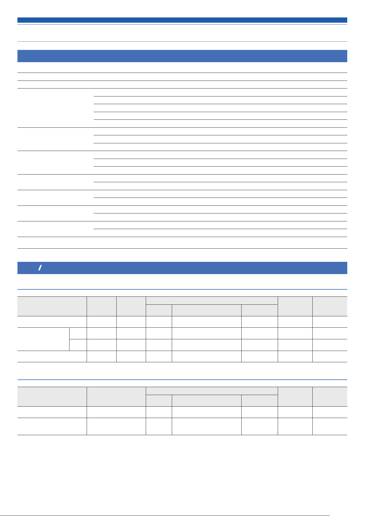
Specifications
Other
Phantom power +48 VDC
PAD (Attenuation level) -24 dB
I/O connector INPUT ST Euroblock connectors (3-pin)
INPUT MIC/LINE 5 and 6 Euroblock connectors (3-pin)
INPUT MIC 1 to 4 Euroblock connectors (3-pin)
OUTPUT UNBAL Euroblock connectors (3-pin)
OUTPUT BAL 1/L and 2/R Euroblock connectors (3-pin)
Level indicator SIGNAL/PEAK 1 point (Red/Yellow/Green)
Peak indicate (red) -5 to 0 dB
Peak hold time 2 sec
Remote control IP protocol RJ-45×1 pc
IP address 192.168.33.102 (factory default)
Communication speed 100 Mbps
Link I/O IP protocol RJ-45×2 pcs
Communication speed 100 Mbps
USB Type B Channel Stereo input x 1 ch, stereo output x 1 ch (24-bit)
Communication speed High-speed (480 Mbps)
A/D converter Resolution 24-bit
Dynamic range 115 dB
D/A converter Resolution 24-bit
Dynamic range 115 dB
Accessories
Euroblock connector x 10, Rack-mount (large, small), Rack-mount screw x 6, Power
cable, Rubber feet x 4
Input/Output specifications
Analog input specifications
Input terminal Gain
MIC 1 to 4 20 to 60 dB 1.6 kΩ -60 dBu -40 dBu -20 dBu
MIC/LINE 5 and 6 MIC 20 to 60 dB 1.6 kΩ -60 dBu -40 dBu -20 dBu
LINE 20 to 60 dB 10 kΩ -40 dBu +4 dBu / 0 dBV / -10 dBV / -20 dBV +24 dBu
ST (L/R) - 10 kΩ - -10 dBV / -20 dBV +20 dBV
Load
impedance
Minimum
value
Analog output specifications
Output terminal Load impedance
UNBAL (L/R) 150 Ω - -33 dBV / -10 dBV
BAL 1/L and 2/R 150 Ω - -10 dBV / 0 dBV / +4 dBu
Minimum
value
Input level
Nominal value Maximum value
Output level
Nominal value Maximum value
-13 dBV /
+10 dBV
+10 dBV /
+20 dBV /
+24 dBu
Connector
Euroblock
connector
Euroblock
connector
Euroblock
connector
Euroblock
connector
Connector
Euroblock
connector
Euroblock
connector
Balanced/
Unbalanced
Balanced
Balanced
Balanced
Unbalanced
Balanced/
Unbalanced
unbalanced
Balanced
77
Page 79

MAC I/F
System diagram
Audio data
Contral data
Meter
ANALOG INPUT
MIC 1
Balanced
-40dBu
MIC 2
Balanced
-40dBu
MIC 3
Balanced
-40dBu
Digital SmartMixer
ATDM-0604
HA Gain
+20dB ~ +60dB
Channel 1
Channel 2
Channel 3
1.0dB step
+48V
HA
ADC
Trim
Phase
Audio data
Control data
Meter
Low Cut
4 Band PEQ
Same as CH1
Same as Channel 1
Same as Channel 1
Level
IN 1
Mute
OFF
IN 2
IN 3
SmartMixer
(Gate/Gain Sharing)
SM
1
SM
2
SM
ST
Pre
Post
Post
Post
Post
OFF
AEC Detect
AEC Detect
Pre
Pre
Pre
Lv Meter
ST(R)
ST(L)
MAIN1/L
Assign
Assign
Assign
MAIN2/R
Delay Time
0 ~ 1000msec
OUT1
OUT2
ST(L)
ST(R)
from
SmartMixer Gate
NOMA
from
SmartMixer Gate
NOMA
from
SmartMixer Gate
from
SmartMixer Gate
NOMA
Delay
1msec step
FBS
PEQ
Same as OUT1
Same as OUT1NOMA
Same as OUT1
Lv Meter
Level12 Band8 Band
Dyn
Output Flip
OFF
ON
OFF
ON
OFF
ON
OFF
ON
Unity
Unity
Output unity 2 steps
Unity
Unity
AEC
ANALOG OUTPUT
Output unity 3 steps
+4dBu, 0dBV, -10dBV
BTL
DAC
BTL
DAC
-10dBV, -33dBV
DAC
DAC
OUT1
Balanced
OUT2
Balanced
ST (L/R)
Unbalanced
MIC 4
Balanced
-40dBu
MIC/LINE 5
Balanced
-40dBu/
+4dBu/0dBV/
-10dBV/-20dBV
MIC/LINE 6
Balanced
-40dBu/
+4dBu/0dBV/
-10dBV/-20dBV
Channel 4
Channel 5
MIC:ON/OFF
LINE:OFF
Channel 6
Mic:ON/OFF
Line:OFF
+48V
+20dB ~ +60dB
24dB
PAD
MIC:OFF
LINE:ON
HA Gain
1.0dB step
HA
ADC
Same as Channel 1
Low Cut
Phase Mute
4 Band PEQ
LevelTrim
Same as Channel 5
IN 4
AEC Detect
Assign
Mono
AEC Detect
OUT 1
OUT 2
OUT ST
USB AUDIO OUTPUT
OFF
OUT1
OUT2
ST(L)
OUT1
OUT2
ST(R)
AEC
OFF
AEC
Lv Meter
Pre
IN 5
OFF
IN 6
Post
Mono
Stereo Pair
OFF
ON
OFF
ON
OFF
ON
OFF
ON
OFF
ON
OFF
ON
Assign
Pre
SM
1
SM
2
SM
ST
Post
Pre
Post
Pre
Post
OFF
AEC Detect
AEC Detect
Output Level
Output Level
USB AUDIO OUT1
USB AUDIO OUT2
ST (L/R)
Unbalanced
-10dBV/-20dBV
USB AUDIO INPUT
USB AUDIO IN1
USB AUDIO IN2
Audio-Technica LINK
ATDM-0604
ST(L)
ST(R)
BUS_MAI N1/L
MAC I/F
BUS_MAI N2/R
BUS_ST(MONO)
AEC_REF
Volume
-30dB ~ +10dB
1.0dB step
LINE
ADC
USB
LINE
ADC
USB
Volume
Volume
4 Band PEQ
4 Band PEQ
Level
Level
Mute
OFF
Mute
OFF
Mono
AEC Reference
IN 1
IN 2
IN 3
IN 4
IN 5
IN 6
IN ST
OUT 1
OUT 2
OUT ST
Externa l
IN ST
Post
Selector
Lv Meter
Pre
Ref.Level
Send Reference
for exte rnal
AEC
Stereo
Mono
Stereo
NC Processing
NC
AEC refere nce in
AEC Processing
AEC NLP NC
AEC detect in
Assign
Output
BUS
OFF
Audio-Technica LINK
Audio-Technica LINK
Mode
ATDM-0604
78
Page 80

Audio-Technica Corporation
2-46-1 Nishi-naruse, Machida, Tokyo 194-8666, Japan
©2017 Audio-Technica Corporation
222304240-02-01
ver.1 2017.12.01
 Loading...