

Audio-Technica AT8647QM-S, AT8647QM, AT8646QM, AT8646AM User Manual
Professional
Microphone Accessories
AT8646AM, AT8646QM, AT8647QM/S
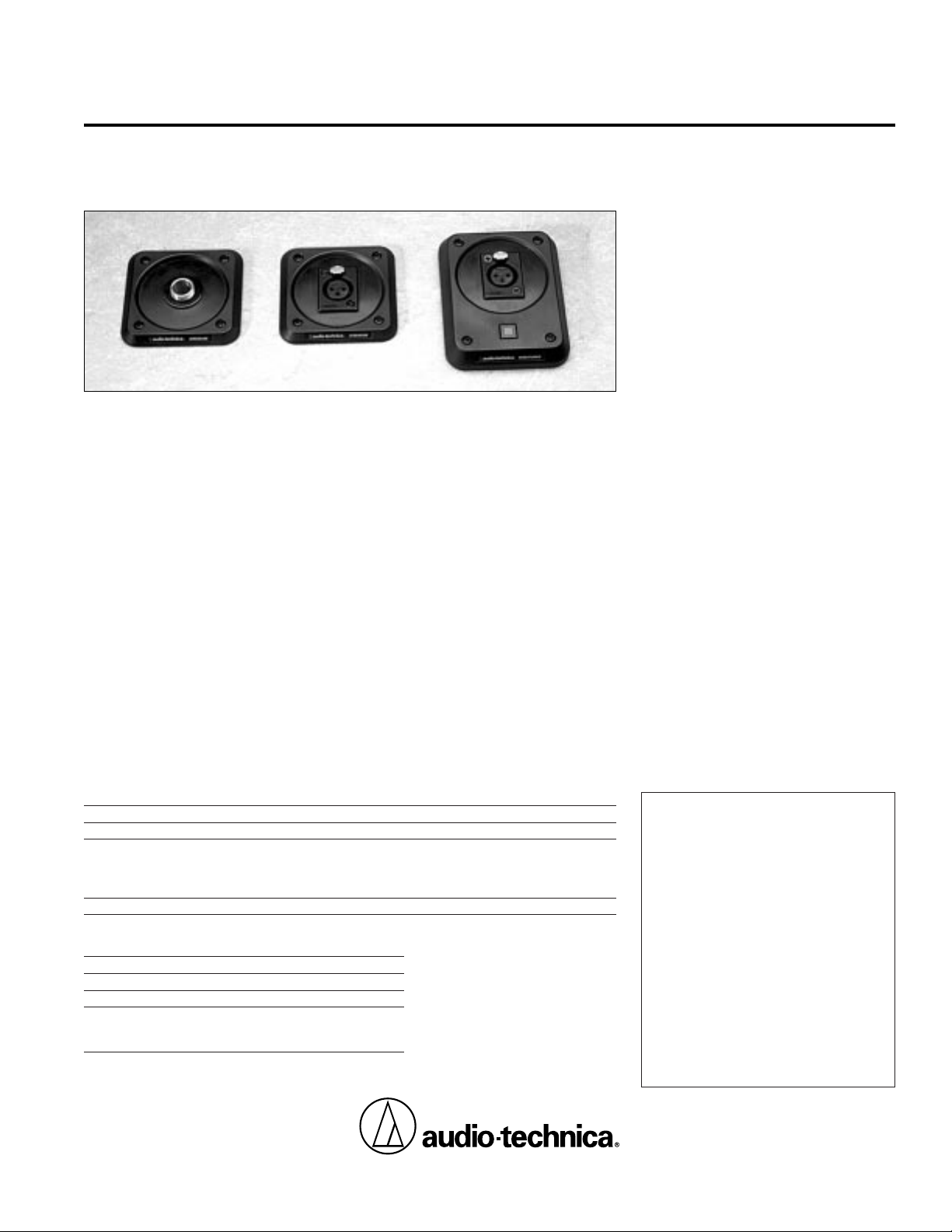
SHOCK-MOUNT PLATES
Description
These Audio-Technica shock-mount plates
effectively isolate mounted microphones
from impact vibration and mechanical noise
normally transmitted from the surface.
They are intended for use with microphones
mounted on lecterns, pulpits, conference
tables and similar surfaces. Designed especially for UniPoint® gooseneck microphones,
they may be used with other lightweight
microphones as well.
All three models incorporate a sturdy yet
flexible suspension panel which provides the
mechanical isolation. The AT8646AM has a
5
/8"-27 threaded adapter-mount, while the
AT8646QM is fitted with an XLRF connector
for lightweight plug-in mics with XLRM
outputs. The AT8647QM/S accepts plug-in
mics and features a phantom-powered mute
switch with a lighted “on” indicator.
Installation
AT8646AM/QM
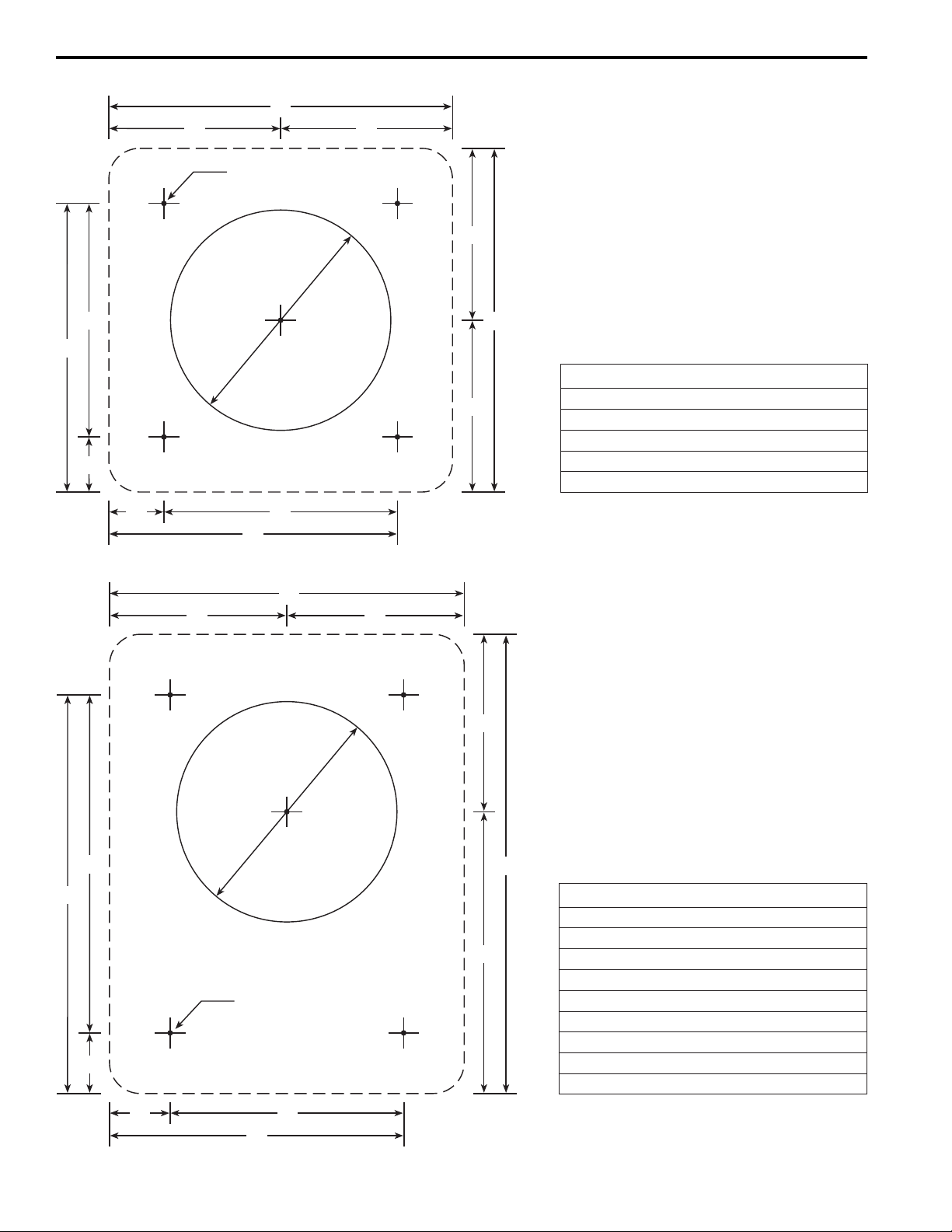
Following the dimensions in Figure 1 on the
back of this sheet, drill a 2" clearance hole
and four small pilot holes for screws in the
One-Year Limited Warranty
Audio-Technica microphones and accessories purchased
in the U.S.A. are warranted for one year from date of
purchase by Audio-Technica U.S., Inc. (A .T.U.S.) to be
free of defects in materials and workmanship. In event
of such defect, product will be repaired promptly
without charge or, at our option, replaced with a new
product of equal or superior value if delivered to A.T.U.S.
or an Authorized Service Center, prepaid, together with
the sales slip or other proof of purchase date.
Prior
approval from A.T.U.S. is required for return.
This
warranty excludes defects due to normal wear, abuse,
shipping damage, or failure to use product in accordance
with instructions. This warranty is void in the event of
unauthorized repair or modification.
For return approval and shipping information,
contact the Service Department, Audio-Technica U.S.,
Inc., 1221 Commerce Drive, Stow, Ohio 44224.
Except to the extent precluded by applicable state law,
A.T.U.S. will have no liability for any consequential,
incidental, or special damages; any warranty of
merchantability or fitness for particular purpose
expires when this warranty expires.
This warranty gives you specific legal rights, and you
may have other rights which vary from state to state.
Outside the U.S.A., please contact your local dealer for
warranty details.
Audio-Technica U.S., Inc., 1221 Commerce Drive, Stow, Ohio 44224
Audio-Technica Limited, Old Lane, Leeds LS11 8AG England
Form No. 0315-7056-00-B/W © 1997 Audio-Technica U.S., Inc. Printed in U.S.A.
mounting surface. A smooth, horizontal
(not tilted) surface is preferred for best
performance.
AT8646AM mounting/connections: Attach
the shock-mount plate to the mounting
surface with the included screws, or with #6
hardware. If possible, route the integral mic
cable down through the mic’s
5
/8"-27 threaded
collar. Secure the cable to the bottom of the
mounting surface
near
the shock mount,
using a cable clamp or similar method.
Leave
a small “loop” of cable hanging freely below
the shock mount.
If the cable is pulled snug,
it will “bypass” the suspension and reduce its
effectiveness.
AT8646QM mounting/connections:
Connect a flexible two-wire shielded cable,
such as AT8300, to the screw-terminals on
the bottom of the AT8646QM, after bringing
the cable-end up through the 2" mounting
hole.
Note that the terminal order is 1-3-2.
The terminal numbers are on the circuit board
and on the terminal strip. Connect the shield
to Terminal 1, balanced signal/phantom power
to Terminals 2 and 3. Connect the “positive”
signal lead to Terminal 2, in
accordance with industry convention. Make
certain that the screw-terminals are on the
bare wire strands, not the insulation, and that
there are no bare wires or loose strands that
could touch each other.
Once the wiring is complete, carefully
position the shock mount on the mounting
surface and attach it with the included
screws, or with #6 hardware. Secure the mic
cable to the bottom of the mounting
surface
near
the shock mount, using a cable
clamp or similar device.
Leave a small “loop”
of cable hanging freely below the shock
mount.
If the cable is pulled snug, it will
“bypass” the suspension and reduce its
effectiveness. Securing the cable also helps
protect the screw-terminal connections.
AT8647QM/S
Following the dimensions in Figure 2, drill a
2” clearance hole and four small pilot holes
for screws in the mounting surface. A
smooth, horizontal (not tilted) surface is
preferred for best performance.
Mounting/connections: The AT8647QM/S
installs in exactly the same manner as the
AT8646QM. Refer to the “AT8646QM
mounting/connections” section above.
Mute switch: The AT8647QM/S features a
press-on/press-off switch that controls the
microphone, muting it by 50 dB at 1,000 Hz.
The circuitry also operates a light in the
switch, powered by the 24-48V phantom
source, to indicate when the mic is “on.”
Regardless of the switch position, the actual
mic operating voltage will be approximately
10-12V less than the phantom source voltage.
Mechanical Specifications
AT8646AM AT8646QM AT8647QM/S
Mic attachment
5
/8"-27 threads XLRF-type XLRF-type
Dimensions
Width 3.07" (78.0 mm) 3.07" (78.0 mm) 3.17" (80.5 mm)
Depth 3.07" (78.0 mm) 3.07" (78.0 mm) 4.10" (104 mm)
Height 0.33" (8.4 mm) 0.33" (8.4 mm) 0.61" (15.5 mm)
Weight 2.0 oz (58 grams) 2.3 oz (64 grams) 3.5 oz (99 grams)
AT8647QM/S Electrical Specifications
Phantom power 24-48V DC, 3 mA typical
Output impedance 360 ohms
Insertion loss* 1 dB
Mute attenuation* 50 dB at 1000 Hz
35 dB at 100 Hz
30 dB at 50 Hz
*150 ohm source, 100k ohm load
AT8646AM, AT8646QM, AT8647QM/S
MOUNTING TEMPLATES
PILOT HOLES
4 PLACES
2" DIA.
THRU-HOLE
(50 mm)
B B
B
B
E
D
C
E
D
C
A
A
Dimension .00"
x
/x" mm
A 3.07" 35/64" 78.0 mm
B 1.54" 117/32" 39.0 mm
C 0.49"
31
/64" 12.5 mm
D 2.58" 237/64" 65.5 mm
E 2.09" 23/32" 53.0 mm
Figure 1: AT8646AM & AT8646QM
G
H
J
L
K
N
P
PILOT HOLES
4 PLACES
2" DIA.
THRU-HOLE
(50 mm)
M
F
(FRONT)
HH
K
Dimension .00"
x
/x" mm
F 3.17" 311/64" 80.5 mm
G 4.10" 43/32" 104.2 mm
H 1.58" 137/64" 40.3 mm
J 2.52" 233/64" 63.9 mm
K 0.54"
35
/64" 13.8 mm
L 2.09" 23/32" 53.0 mm
M 2.63" 25/
8
" 66.8 mm
N 3.02" 31/64" 76.7 mm
P 3.56" 39/16" 90.5 mm
Figure 2: AT8647QM/S
 Loading...