


 Loading...
Audioscan Verifit®
User's Guide 4.2
© June 2015
Table of Contents |
|
|
1 |
About Verifit.......................................................................................................................................................................... |
6 |
|
Product description............................................................................................................................................................... |
6 |
|
Accessories......................................................................................................................................................................... |
12 |
|
Associated items and supplies............................................................................................................................................ |
13 |
|
SAFETY WARNINGS and NOTICES.............................................................................................................................. |
13 |
|
Environmental safety.......................................................................................................................................................... |
14 |
|
Declaration of Electromagnetic Compatibility (EMC)..................................................................................................... |
14 |
|
Warranty, Trademarks, Acknowledgments....................................................................................................................... |
15 |
|
EC Declaration of Conformity........................................................................................................................................... |
17 |
|
Electronic User’s Guide..................................................................................................................................................... |
18 |
|
How to Avoid Undesirable Side Effects............................................................................................................................ |
18 |
2 |
Getting Started..................................................................................................................................................................... |
20 |
|
Office setups....................................................................................................................................................................... |
20 |
|
Unpacking and connecting................................................................................................................................................. |
20 |
|
Microphone connection...................................................................................................................................................... |
21 |
|
General care instructions.................................................................................................................................................... |
23 |
|
Microphone care................................................................................................................................................................. |
24 |
|
Mouse and keyboard........................................................................................................................................................... |
24 |
|
Monitor headphones........................................................................................................................................................... |
24 |
|
External peripherals............................................................................................................................................................ |
26 |
3 |
General Operation................................................................................................................................................................ |
28 |
|
Switching ON/OFF............................................................................................................................................................. |
28 |
|
Input device operation........................................................................................................................................................ |
28 |
|
Network connection............................................................................................................................................................ |
30 |
|
Printer connection............................................................................................................................................................... |
31 |
|
Menus, lists and buttons..................................................................................................................................................... |
32 |
|
Screen messages and Help................................................................................................................................................. |
32 |
|
Software updating............................................................................................................................................................... |
32 |
4 |
General Setup....................................................................................................................................................................... |
34 |
|
Date and time setup............................................................................................................................................................ |
34 |
|
Display settings................................................................................................................................................................... |
34 |
|
Saving test setup................................................................................................................................................................. |
34 |
5 |
On-Ear Measures - Setup..................................................................................................................................................... |
36 |
|
External sound-field speaker setup.................................................................................................................................... |
36 |
|
On-ear calibration facts...................................................................................................................................................... |
37 |
|
Calibration of on-ear probe microphone............................................................................................................................ |
37 |
|
Calibration check for probe module.................................................................................................................................. |
39 |
|
Max TM SPL setup............................................................................................................................................................ |
40 |
|
ABR nHL to eHL setup...................................................................................................................................................... |
40 |
|
Positioning the client.......................................................................................................................................................... |
40 |
|
Positioning the probe tube.................................................................................................................................................. |
41 |
6 |
On-Ear Measures Screen Setup........................................................................................................................................... |
43 |
|
On-ear single or dual view................................................................................................................................................. |
43 |
|
Graph, table or 2cc target format....................................................................................................................................... |
43 |
|
SPL or HL scale.................................................................................................................................................................. |
43 |
|
Hide or show on-ear curves................................................................................................................................................ |
43 |
7 Speechmap........................................................................................................................................................................... |
45 |
|
|
Speechmap facts................................................................................................................................................................. |
45 |
|
DSL 5.0 in Speechmap....................................................................................................................................................... |
45 |
|
NAL-NL1 in Speechmap.................................................................................................................................................... |
46 |
|
NAL-NL2 in Speechmap.................................................................................................................................................... |
46 |
|
Camfit in Speechmap......................................................................................................................................................... |
47 |
|
Using Speechmap............................................................................................................................................................... |
47 |
|
Speechmap Setup................................................................................................................................................................ |
47 |
|
Screen tour - unaided screen.............................................................................................................................................. |
49 |
|
Screen tour - aided screen.................................................................................................................................................. |
50 |

|
Verifit®User's Guide Version 4.2 © June 2015 |
|
|
On-ear or Test box mode.................................................................................................................................................... |
50 |
|
SII calculation in Speechmap............................................................................................................................................. |
51 |
|
Using custom stimuli in Speechmap.................................................................................................................................. |
51 |
|
Creating WAV files for Speechmap.................................................................................................................................. |
53 |
8 |
Speechmap Fitting Procedures............................................................................................................................................ |
55 |
|
Speechmap screen choices................................................................................................................................................. |
55 |
|
Data entry........................................................................................................................................................................... |
57 |
|
Fitting to targets for soft speech......................................................................................................................................... |
57 |
|
Fitting to targets for average speech ................................................................................................................................. |
58 |
|
Adjusting the Maximum Output Level.............................................................................................................................. |
59 |
|
Open fittings in Speechmap............................................................................................................................................... |
60 |
|
Verifying Frequency Compression/ Frequency-Lowering Hearing Instruments in Speechmap...................................... |
61 |
|
Binaural fitting in Speechmap........................................................................................................................................... |
62 |
|
CROS fitting in Speechmap............................................................................................................................................... |
63 |
|
T-Loop fitting and verification in Speechmap.................................................................................................................. |
64 |
|
Tele-test fitting and verification in Speechmap................................................................................................................ |
65 |
|
FM fitting and verification................................................................................................................................................. |
66 |
|
How to Verify with Calibrated 'S' and 'SH' Stimuli.......................................................................................................... |
66 |
9 |
Speechmap Technical Details.............................................................................................................................................. |
68 |
|
Wideband measurements in Speechmap............................................................................................................................ |
68 |
|
Speechmap stimuli............................................................................................................................................................. |
68 |
|
Stimulus spectra.................................................................................................................................................................. |
69 |
|
Microphone location effects............................................................................................................................................... |
70 |
|
Deep insertion compensation............................................................................................................................................. |
70 |
|
Speech signal analysis........................................................................................................................................................ |
71 |
10 |
On-Ear Instrument Measures............................................................................................................................................. |
72 |
|
On-ear directional test overview........................................................................................................................................ |
72 |
|
On-ear directional testing................................................................................................................................................... |
72 |
|
On-ear feedback test........................................................................................................................................................... |
73 |
|
On-ear noise reduction test................................................................................................................................................. |
73 |
|
On-ear manual control........................................................................................................................................................ |
74 |
|
Sound level meter using on-ear microphones.................................................................................................................... |
74 |
11 WRECD measurement....................................................................................................................................................... |
76 |
|
|
Calibration of WRECD Transducer................................................................................................................................... |
76 |
|
Measure WRECD .............................................................................................................................................................. |
76 |
|
WRECD results.................................................................................................................................................................. |
78 |
|
WRECD protocols.............................................................................................................................................................. |
78 |
|
WRECD facts..................................................................................................................................................................... |
80 |
12 |
Occlusion Effect Test......................................................................................................................................................... |
81 |
|
Occlusion effect measurement........................................................................................................................................... |
81 |
13 |
Sensory loss simulator....................................................................................................................................................... |
82 |
|
Sensory loss simulator description..................................................................................................................................... |
82 |
|
Sensory loss simulator operation....................................................................................................................................... |
82 |
14 |
Insertion Gain..................................................................................................................................................................... |
84 |
|
Insertion gain in SPL.......................................................................................................................................................... |
84 |
|
Insertion gain in HL........................................................................................................................................................... |
85 |
|
Audiometric data entry....................................................................................................................................................... |
86 |
|
REUR measurement procedure.......................................................................................................................................... |
87 |
|
REAR measurement procedure.......................................................................................................................................... |
88 |
|
SII calculation in Insertion gain......................................................................................................................................... |
88 |
|
CROS fitting using Insertion gain...................................................................................................................................... |
89 |
15 |
Test Box Measures - Setup................................................................................................................................................ |
91 |
3

|
Verifit®User's Guide Version 4.2 © June 2015 |
|
|
Test box screen................................................................................................................................................................... |
91 |
|
Format................................................................................................................................................................................. |
93 |
|
Scale.................................................................................................................................................................................... |
93 |
|
Hide or Show test box curves............................................................................................................................................. |
93 |
|
ANSI test frequencies......................................................................................................................................................... |
94 |
|
Test box calibration facts................................................................................................................................................... |
95 |
|
Calibrating test box reference microphone........................................................................................................................ |
95 |
|
Calibration check for coupler microphone........................................................................................................................ |
96 |
|
Coupling for binaural/wideband tests................................................................................................................................ |
96 |
|
Positioning HI for binaural/wideband tests........................................................................................................................ |
97 |
|
Coupling for ANSI tests..................................................................................................................................................... |
98 |
|
Positioning HI for ANSI tests............................................................................................................................................ |
99 |
16 |
ANSI Hearing Aid Tests.................................................................................................................................................. |
101 |
|
ANSI S3.22-2003 facts..................................................................................................................................................... |
101 |
|
ANSI 2003 Linear and AGC tests.................................................................................................................................... |
101 |
|
ANSI test results............................................................................................................................................................... |
102 |
|
ANSI input-output curves................................................................................................................................................ |
102 |
|
ANSI telecoil terminology............................................................................................................................................... |
103 |
|
ANSI telephone simulator (TMFS) test........................................................................................................................... |
103 |
|
ANSI test loop test............................................................................................................................................................ |
104 |
|
Telecoil test results........................................................................................................................................................... |
106 |
17 |
Other Test Box Measures................................................................................................................................................ |
107 |
|
Harmonic distortion.......................................................................................................................................................... |
107 |
|
Noise reduction................................................................................................................................................................. |
107 |
|
Directional function test................................................................................................................................................... |
108 |
|
Directional ITE positioning.............................................................................................................................................. |
108 |
|
Directional BTE positioning............................................................................................................................................ |
109 |
|
Test box directional procedure......................................................................................................................................... |
110 |
|
Multicurve procedure....................................................................................................................................................... |
111 |
|
Multicurve results............................................................................................................................................................. |
111 |
|
Spectral analysis in Multicurve........................................................................................................................................ |
112 |
|
Battery drain test.............................................................................................................................................................. |
112 |
|
Manual control procedure................................................................................................................................................ |
113 |
|
Sound level meter using manual control......................................................................................................................... |
114 |
18 |
Networking....................................................................................................................................................................... |
116 |
|
Networking standards....................................................................................................................................................... |
116 |
|
Network setup................................................................................................................................................................... |
116 |
|
Remote Operation............................................................................................................................................................. |
118 |
|
Changing the Remote Operation settings........................................................................................................................ |
118 |
|
NOAH Service Port.......................................................................................................................................................... |
119 |
|
Changing the NOAH service port.................................................................................................................................... |
119 |
|
Testing the NOAH service port........................................................................................................................................ |
120 |
|
Web Service Port.............................................................................................................................................................. |
120 |
19 |
Single Computer Connection........................................................................................................................................... |
122 |
|
Automatic connection (recommended)............................................................................................................................ |
122 |
|
Static connection.............................................................................................................................................................. |
122 |
20 |
Printing and Storing Results............................................................................................................................................ |
124 |
|
Storing data in NOAH...................................................................................................................................................... |
124 |
|
Printing results.................................................................................................................................................................. |
124 |
|
Printing setup.................................................................................................................................................................... |
124 |
|
Printer connection............................................................................................................................................................. |
125 |
|
Printer types...................................................................................................................................................................... |
126 |
4

|
Verifit®User's Guide Version 4.2 © June 2015 |
|
|
HP printer.......................................................................................................................................................................... |
126 |
|
Custom printer.................................................................................................................................................................. |
126 |
|
File output......................................................................................................................................................................... |
127 |
|
Page setup......................................................................................................................................................................... |
127 |
|
Windows-shared printers and folders............................................................................................................................... |
129 |
|
Network printer................................................................................................................................................................. |
131 |
|
Web browser screen capture............................................................................................................................................ |
131 |
|
Session setup..................................................................................................................................................................... |
132 |
|
Storing and restoring session files.................................................................................................................................... |
133 |
21 |
Troubleshooting............................................................................................................................................................... |
135 |
|
Self test failures................................................................................................................................................................ |
135 |
|
Initialize Function............................................................................................................................................................ |
135 |
|
Inconsistent levels in speech stimulus............................................................................................................................. |
136 |
|
Test box high distortion or noise...................................................................................................................................... |
136 |
|
Test box curves inconsistent............................................................................................................................................ |
136 |
|
Test box curves differ from specifications...................................................................................................................... |
136 |
|
Test box speaker overdriven............................................................................................................................................ |
137 |
|
No test box reference mic. detected................................................................................................................................. |
137 |
|
Invalid test box calibration............................................................................................................................................... |
137 |
|
Unable to calibrate test box microphone......................................................................................................................... |
137 |
|
No on-ear ref. mic. detected............................................................................................................................................. |
138 |
|
Invalid on-ear calibration................................................................................................................................................. |
138 |
|
Unable to calibrate on-ear microphone............................................................................................................................ |
138 |
|
Sound-field speaker overdriven....................................................................................................................................... |
139 |
|
Invalid binaural equalization............................................................................................................................................ |
139 |
22 |
Technical Specifications.................................................................................................................................................. |
140 |
23 |
Glossary............................................................................................................................................................................ |
147 |
24 |
References........................................................................................................................................................................ |
152 |
25 Appendix 1....................................................................................................................................................................... |
155 |
|
|
Manufacturer Disclosure Statement for Medical Device Security................................................................................. |
155 |
5

Verifit®User's Guide Version 4.2 © June 2015
1 About Verifit
This section provides a listing of features new in this software release, describes the Audioscan Verifit, provides contact, warranty and trademark information, safety warnings and notices and instructions for accessing the electronic User’s Guide.
Note that the User's Guide may be viewed on the Verifit at any time by pressing <Help>. (For long Help pages, use the mouse to switch between the Help index and the Help page, and to scroll through the page).
Product description
The Verifit is a hearing instrument analyzer intended to be used by hearing care professionals such as audiologists and hearing instrument specialists to verify the electro-acoustic performance of a hearing instrument connected to a standard earphone coupler or while worn on the ear of the end user. The Verifit is a Programmable Electrical Medical System (PEMS). The system consists of a real-ear measurement (REM) display unit, a hearing instrument test (HIT) acoustically-treated binaural test box, and numerous attachable components and accessories:
Display Unit
A real-ear measurement (REM) display unit housing a flatpanel LCD high resolution display, signal generation, measurement and control electronics, and two sound-field loudspeakers.
On the sides of the display unit, there are connections for: 1.monitor headphones on the lower right side
2.a USB jack on the lower left side (for the Audioscan update stick, for example)
3.magnet mounts on both sides of the display unit, approximately 8cm (3 in.) down from the top (this is where you store the probe dock when not in use)
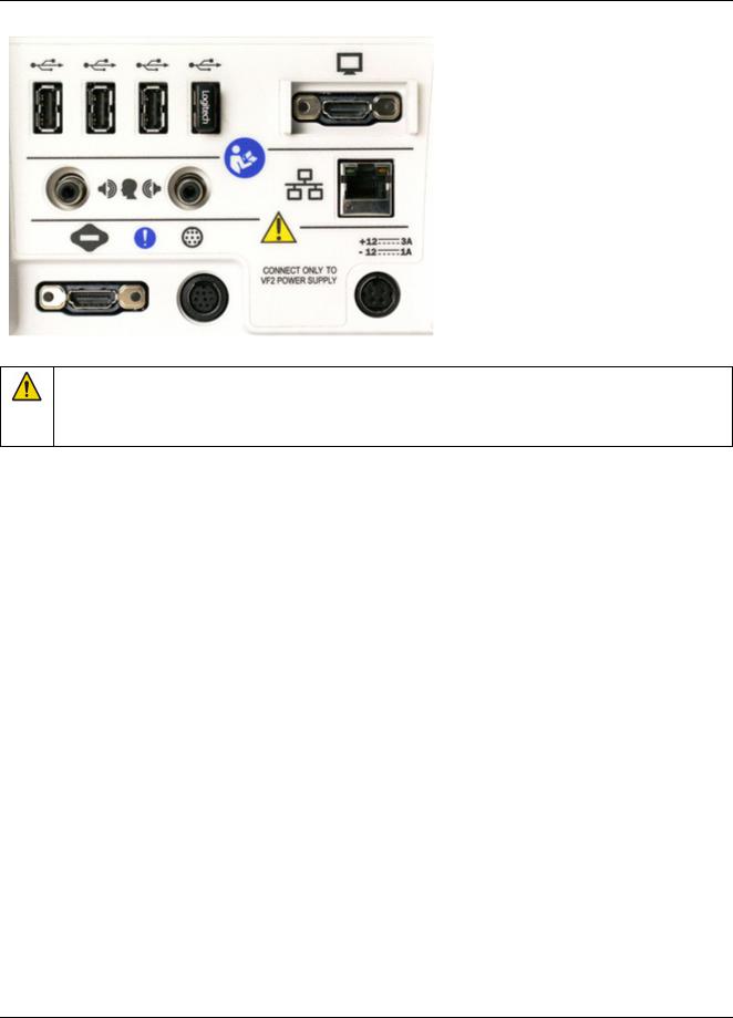
On the rear of the display unit, there are connections for: 1.an external monitor
2.a network connection 3.external loudspeakers 4.power supply
5.test box cable 6.probe dock cable
7.four USB jacks (for a keyboard, printer, and a mouse) - the USB stick for the mouse is already
inserted into one of these USB jacks
The following components are shipped with the display unit
6

|
Verifit®User's Guide Version 4.2 © June 2015 |
|
|
|
|
Component |
|
Description |
|
|
External power supply connected to a hospital grade power |
|
|
cord (in North America) or a country-specific power cord |
|
|
(international markets) . |
|
|
Electrical supply input requirement: 100 – 240 Vac |
|
|
47 – 63 Hz 1.35 – 0.53 A |
|
|
|
|
|
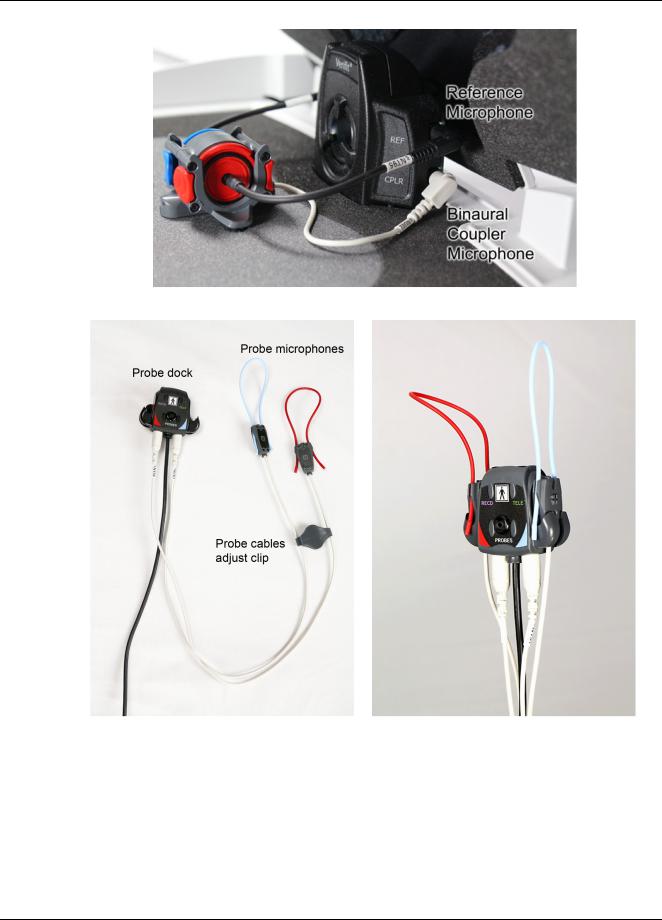
Probe dock, shown here with 2 probe microphones (which |
|
|
nest into, and are connected to, the probe dock). This is the |
|
|
configuration of these components when they are shipped to |
|
|
you. |
|
|
The probe dock has connections for the 2 probe microphones, |
|
|
the WRECD transducer, and the tele-test handset. It is intended |
|
|
that the probe dock clips near to or on the patient. |
|
|
There is a probe cables adjust clip on the probe microphone |
|
|
cables that allows you to adjust the probe microphones flat |
|
|
against the client's cheek |
|
|
|
|
|
Probe tubes, package of 36 |
|
|
|
7

Verifit®User's Guide Version 4.2 © June 2015
Component |
Description |
WRECD transducer |
used to measure the wideband real-ear |
to coupler difference (WRECD) useful in estimating the sound |
|
level produced in an individual ear from measurements in a |
|
coupler |
|
Foam eartips for measuring WRECD. The package contains:
•Qty 5 ER3-14A adult foam eartips
•Qty 5 ER3-14B pediatric foam eartips
Wireless mouse
Monitor headphones provided with 2 detachable (detachable from the headphone) cables, each having 3.5mm stereo plugs on each end. The cables are 130cm (51 in.) and 365cm (12 feet) in length
a 3.5cm to 1/4-inch adapter plug is also provided (to connect to the 1/4-inch headphone jack on the display unit)
8

|
Verifit®User's Guide Version 4.2 © June 2015 |
|
|
Component |
Description |
|
Tele-test handset used to provide an inductive stimulus for |
|
simulating operation with a telephone in Speechmap and for |
|
performing ANSI TMFS test. |
Audioscan update USB stick
Quickstart setup guide
9

Verifit®User's Guide Version 4.2 © June 2015
Test Box
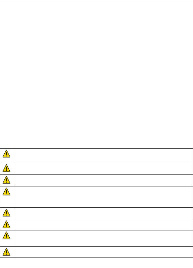
Hearing instrument test (HIT) acoustically-treated binaural test box which houses a telecoil test loop, 3 loudspeakers and connections for:
•two reference microphones,
•binaural coupler microphone
•battery pill substitutes
The following components are shipped with the test box
Component |
Description |
|
Test box cable to connect the test box to the display unit |
Binaural coupler microphone for the purpose of measuring the sound level produced in the standard coupler by a hearing instrument
Testbox reference microphones for controlling the signal from the loudspeakers (2)
10
Verifit®User's Guide Version 4.2 © June 2015
Component |
Description |
|
|
0.4cc wideband couplers that are attached to the binaural |
|
|
coupler microphone |
|
|
|
|
|
HA-1 |
(ITE) 2cc coupler (1) |
|
|
|
|
HA-2 |
(BTE) 2cc coupler (1) |
|
|
|
|
Hearing instrument stabilizers, attached to the 0.4cc |
|
|
couplers to support BTE-style instruments |
|
|
|
|
|
|
|
11

|
Verifit®User's Guide Version 4.2 © June 2015 |
||
|
|
|
|
Component |
|
Description |
|
|
|
TRIC adapters (Thin-tube, Receiver In Canal) designed |
|
|
|
for use with 0.4cc and HA-1 (ITE) 2cc couplers |
|
|
|
|
|
|
|
Earmold substitutes (HA-4 tubing) inserted in a second |
|
|
|
set of TRIC adapters to allow BTE instruments to be |
|
|
|
coupled to the 0.4cc coupler without earmold |
|
|
|
|
|
|
|
Putty, to attach custom hearing instruments and earmolds |
|
|
|
to the coupler 0.4cc and HA-1 (ITE) 2cc couplers |
|
|
|
|
|
|
|
Battery pill substitutes, kit consisting of: |
|
|
|
1 - E352 |
Battery Size #10A |
|
|
1 - E353 |
Battery Size #13A |
|
|
1 - E354 |
Battery Size #312 |
|
|
1 - E355 |
Battery Size #675 |
|
|
|
|
Accessories
RE367-36 probe tubes for single patient use (36 per bag)
12
Verifit®User's Guide Version 4.2 © June 2015
ER3-14A and ER3-14B foam eartips (package containing 5 of each)
Associated items and supplies
VA-111 External speaker with folding stand
VA-131 Microphone extension cable (90cm / 36 in.) for use with binaural coupler microphone VA-134 Probe dock extension cable (375cm / 12 ft.) for use with the probe dock
VA-201 NOAH® module allows a networked PC running NOAH to exchange data with Audioscan analyzers RE-790 Binaural coupler microphone adapter for use with QUEST CA22 calibrator (1-1/8 in.)
RE-791 Binaural coupler microphone adapter for use with QUEST QC 10/20 calibrators (1 in.)
SAFETY WARNINGS and NOTICES
For purposes of IEC 60601-1, this product is Class I with Type BF applied parts. The applied parts are: 1.Probe tube
2.Foam eartip 3.Probe microphone
This device complies with Part 15 of the FCC Rules. Operation is subject to the following two conditions:
(1) this device may not cause harmful interference, and (2) this device must accept any interference received, including interference that may cause undesired operation
This Class A digital apparatus complies with Canadian ICES-003
This symbol on the product is a WARNING describing a foreseen risk
WARNING: To avoid the risk of electrical shock, use only the power supply and power cord supplied with the Verifit and connect it only to a grounded (protectively earthed) electrical outlet.
WARNING: To allow electrical power to be rapidly disconnected in the event of an emergency, position the power supply in an accessible location so that the power cord may be quickly disconnected.
WARNING: To avoid the risk of electrical shock, any line-powered peripheral equipment connected to this product must comply with UL/IEC 60601-1 OR comply with UL or IEC and ISO safety standards for such equipment AND a) be operated from an isolating transformer complying with UL/IEC 60601-1 OR b) be kept at least 1.8m (6 ft.) from the patient.
WARNING: This equipment is not suitable for use in an oxygen-rich environment or in the presence of flammable anesthetic mixtures with air or with oxygen or nitrous oxide.
WARNING: To ensure proper operation of this product, no modification of this equipment is permitted
WARNING: Probe tubes are for single-patient use only. Care is required when sliding the probe tube into the ear canal. Be careful not to advance the probe tube further into the ear canal when inserting an earmold or custom hearing instrument into the ear or when inserting the foam tip into the ear
WARNING: Foam eartips are for single-patient use only
13

Verifit®User's Guide Version 4.2 © June 2015
WARNING: To ensure that the operation of this product is not affected by EMC emissions from other products, this product should not be used adjacent to or stacked on other equipment. If this is necessary, its operation should be verified as normal in this configuration. Portable and mobile RF communications equipment can affect the performance of this product
WARNING: To reduce the risk of contamination, hearing instruments should be clean before putty is applied and putty should be replaced frequently
WARNING: The included magnet may effect some medical or electronic devices. Keep magnet at least 5cm (2in.) from implantable devices and other magnetically sensitive devices.
WARNING: Keep magnet out of reach of children and pets. If a magnet is swallowed seek immediate medical attention.
This symbol on the product is a WARNING that failure to follow instructions in this part of the User’s and/or Quick Start Guides could place the operator or patient at risk.
Failure to follow the operating instructions for connecting to a network, a local printer, a keyboard, or an external monitor could place the operator at risk
Failure to follow the operating instructions for connecting the monitor headphones, the mouse, or the Audioscan update stick could place the operator at risk
This symbol on the product is a WARNING describing a required action
Use only an approved test box cable to connect the test box and the display unit
The test box can only be connected to the display unit
The VF2 power supply can only be connected to the mains using the supplied power cord
The probe dock can only be connected to the display unit
This symbol on the product means that the parts applied to the patient meet the safety requirements of IEC 60601-1 for type BF isolated (floating) applied parts
Environmental safety
This symbol on the product means that this product is not to be disposed of in unsorted municipal waste because electrical and electronic waste may contain hazardous substances which could endanger the environment and human health.
This product and its associated items must be disposed of in accordance with local disposal regulations for electrical and electronic waste. Consult your local waste disposal authority regarding applicable regulations.
The probe tubes (used with the probe microphones) and the foam eartips (used with the WRECD transducer) are for single patient use. After use, they may be disposed of in unsorted municipal waste or as required by your facility's waste management policy.
Declaration of Electromagnetic Compatibility (EMC)
Medical electrical equipment needs special precautions regarding EMC and needs to be installed and put into service according to the following information:
•The Verifit should not be used adjacent to or stacked on other equipment. If this is necessary, its operation
14

Verifit®User's Guide Version 4.2 © June 2015
should be verified as normal in this configuration.
•Portable and mobile RF communications equipment can affect medical electrical equipment and may affect the performance of the Verifit.
•Performance degradation due to electromagnetic disturbances (including electrostatic discharge) is considered normal and acceptable
The compliances listed in the following table are met with the supplied WRECD transducer, binaural coupler microphone, probe microphones, reference microphones, monitor headphones, mouse, and a keyboard, all of which are connected, and with unterminated speaker cables (2), USB cables (5), Ethernet cable, test box cable, and HDMI display cable connected. The connection of other devices may result in increased emissions.
Guidance and manufacturer’s declaration - electromagnetic emissions
The Verifit is intended for use in the electromagnetic environment specified below. The user of the Verifit should assure that it is used in such an environment.
Emissions test |
|
Compliance |
Electromagnetic environment - guidance |
|
|
|
|
RF emissions |
|
|
The Verifit uses RF energy only for internal function. |
|
Group 1 |
Therefore RF emissions are very low and not likely to |
|
CISPR 11 |
|
||
|
|
cause any interference in nearby electronic equipment. |
|
|
|
|
|
RF emissions |
|
Class A |
|
CISPR 11 |
|
The Verifit is suitable for use in all establishments |
|
|
|
||
Harmonic emissions |
|
|
|
|
Class A |
other than domestic and those directly connected to |
|
IEC 61000-3-2 |
|
||
|
|
the public low-voltage power supply network that |
|
Voltage fluctuations/ |
flicker |
|
|
|
supplies buildings used for domestic purposes. |
||
emissions |
|
Complies |
|
|
|
||
IEC 61000-3-3 |
|
|
|
Warranty, Trademarks, Acknowledgments
The Audioscan Verifit is manufactured by Etymonic Design Inc., 20 Ludwig St., Dorchester, Ontario, Canada, N0L 1G4. Web site www.audioscan.com.
Phone: 800-265-2093 (USA only); 519-268-3313 Fax: 519-268-3256 Email: info@audioscan.com or service@audioscan.com
The authorized representative for this product in the European Community is: P.C. Werth, Audiology House, 45 Nightingale Lane, London, UK, SW12 8SP. Phone: +44 (0) 181-675 5151 Fax +44 (0) 181-675 7577.
Warranty: The Verifit is warranted against defects for two years from date of purchase. Within this period, it will be repaired without charge for parts, labor or return shipping when returned prepaid to your authorized Audioscan service agent. This warranty does not apply to equipment that, in our sole judgment, has been subject to misuse, or unauthorized alteration or repair.
Trademarks:
Audioscan, Speechmap, and Verifit are registered trademarks of Etymonic Design Inc. DSL is a registered trademark of Western University. All rights reserved. HP LASERJET is a registered trademark of HewlettPackard Company. NOAH is a registered trademark of the Hearing Instrument Manufacturer's Software Association. QUEST is a trademark of Quest Technologies Inc. PostScript is a registered trademark of Adobe
15

Verifit®User's Guide Version 4.2 © June 2015
Systems, Inc.
Acknowledgments:
DSL 5.0 is used under license from Western University which is solely responsible for its content. We acknowledge the support received from past and present staff at the National Centre for Audiology at Western University in implementing the DSL method.
CAMFIT is used under license from Prof. Brian C.J. Moore, University of Cambridge, UK. We are indebted to the University of Memphis hearing instrument Research Laboratory for permission to use some of their recorded speech material.
NAL-NL1 is used under license from the National Acoustics Laboratories, Australia. NAL-NL2 is used under license from Hearworks Pty Ltd, Australia.
Software licenses:
Audioscan distributes selected software components under various open source licenses. These licenses generally give you the right to copy and change the affected component's software source code. For details, see the license files distributed with the software, or contact Audioscan.
16

Verifit®User's Guide Version 4.2 © June 2015
EC Declaration of Conformity
17

Verifit®User's Guide Version 4.2 © June 2015
Electronic User’s Guide
You can download the current User's Guide directly from www.audioscan.com. A printable User's Guide is also provided with each new instrument and each software update. A .pdf file viewer, such as Acrobat Reader (5.0 or higher) or Foxit Reader is required to view the User’s Guide. Except for some additional reference material, the information in the User's Guide is available to you on the Verifit at any time by right-clicking and selecting  .
.
A printable User’s Guide is on the Audioscan update stick supplied with the instrument. This User's Guide will be updated each time you download new software from www.audioscan.com to the Audioscan update stick.
To view the User's Guide:
1.Insert the Audioscan update stick into a USB port on your PC.
2.If your PC does not open the Audioscan update stick automatically, select My Computer, then the Removable Disk drive (usually E or F).
3.Double click the User_Guide folder to open it.
4.Double click the English folder and copy the Verifit Users Guide.pdf file to an appropriate location on your PC. Double click on the file to open it for viewing.
When you have finished copying the file from the Audioscan update stick, click on the safely remove icon on your PC and remove the Audioscan update stick when you are notified that it is safe to do so.
STORE THE AUDIOSCAN UPDATE STICK IN A SAFE PLACE. YOU WILL REQUIRE IT TO INSTALL FUTURE SOFTWARE UPDATES.
How to Avoid Undesirable Side Effects
During the development of the hearing instrument analyzer, Audioscan performed a rigorous Risk Assessment to identify any undesirable side effects that a user could be exposed to during the use of the Verifit, and incorporated numerous risk reduction design elements into the Verifit to minimize the risk to users and patients.
Following are the actions which a user should take to ensure that these risk control measures continue to be effective
Loud Sounds
The Verifit is designed to produce sound pressure levels as high as 85 dB at the probe reference microphone. Exposure to these levels for more than 7 hours can produce hearing damage. When such levels are amplified by a hearing instrument, the level in the ear canal will be determined by the settings of the hearing instrument but may reach levels that can produce hearing damage in less than 30 seconds. To avoid this possibility,
a)Hearing instruments should be adjusted to limit sound pressure levels to safe levels
b)The maximum TM SPL setting (see Max TM SPL Setup) should be used to terminate tests if an unsafe level is detected in the ear canal
c)Test levels should be limited to 70 dB SPL except when necessary to verify the limiting levels of the hearing instrument, in which case, the test should not last longer than 15 seconds
d)Be aware of the test signal and patient reaction during a test and be prepared to respond to any sign of discomfort by reducing the SPL setting, switching off the equipment or the hearing instrument, or removing the patient from the area.
18

Verifit®User's Guide Version 4.2 © June 2015
When using the equipment to measure the WRECD or RECD in small ear canals, it is possible to induce a hearing loss if the test is allowed to continue for more than 1 hour. Since accurate results can be obtained in less than 10 seconds, this possibility should never occur in normal practice.
Power and Grounding
This product contains numerous safety features to ensure that the probability of electrical shock is as low as reasonably practicable. In order to ensure that all of the safety features work optimally you must ensure that the power cord is plugged into a grounded outlet. Any line-powered peripherals connected to Verifit must comply with UL/IEC 60601-1 OR comply with UL or IEC or ISO safety standards for such equipment, AND a) be operated from an isolating transformer complying with UL/IEC 60601-1, OR b) be kept at least 1.8m (6 ft..) from the patient.
Ear Infection
Probe tubes (used on probe microphones) or foam eartips (used on the WRECD transducer) should not be reused on another patient. There is a possibility of transferring an ear infection to the other patient. Probe tubes and foam eartips are for single-patient use only. Probe tubes can be wiped with alcohol wipes for re-use with the same patient, but must not be used with multiple patients. Do not attempt to clean or re-use the foam eartips.
To avoid cross-contamination between patients, hearing instruments should be cleaned with disinfectant towlettes (e.g., audiowipes) prior to being puttied into a coupler, and the putty should be replaced if it becomes soiled.
Ear Canal Discomfort
An otoscopic examination should always be performed prior to inserting a probe tube into the ear canal to ensure that it is healthy and free of obstructions. Care is needed when inserting probe tubes into the ear canal. Although the probe tubes are made of soft, flexible material specially designed for this application, it is possible to scrape the ear canal or touch the eardrum causing brief discomfort. You should carefully follow the instructions in Positioning the probe tube section of this User’s Guide.
Implantable Electronic Device
The tele-test handset comes with a small magnet attached. This included magnet may affect some medical or electronic devices. Keep the magnet more than 5cm (2 in.) from implantable devices and other magnetically sensitive devices.
All pacemakers respond to a magnet by switching to an asynchronous pacing mode at a programmed atrioventricular (AV) delay and a fixed magnet rate depending on the manufacturer, device model, and the status of the battery. The programmed mode DDD switches to DOO, VVI switches to VOO, and AAI switches to AOO. The rate response feature is switched to 'OFF' on magnet application in pacemakers. In biventricular pacemakers, both the right and left ventricles continue to be paced in the above modes with magnet application so long as the device is at or above ERI. However, from below ERI voltage, this response is unpredictable.
In general, magnet application suspends anti-tachycardia therapy without any effect on the pacing mode. Implantable cardioverter defibrillator models from St. Jude Medical and Boston Scientific, however, have additional programmable features to ignore the magnet or respond differently to a magnet. All biventricular ICDs behave like any other ICDs of the corresponding manufacturer. In most cases, anti-tachycardia therapy resumes with removal of the magnet. However, in some instances, magnet removal may or may not re-enable anti-tachycardia therapy. Specific care should be exercised in Guidant/Boston Scientific ICDs since some of the older models are equipped with circuitry that enables the magnet to permanently programme the antitachycardia therapy to 'OFF'. In addition, magnet application on Sorin ICDs changes the pacing rate without altering the pacing mode. Rate response of ICDs is not influenced by magnet application.
19

Verifit®User's Guide Version 4.2 © June 2015
2 Getting Started
This section provides instructions for unpacking the Verifit and connecting various components and associated items.
Office setups
1. Conventional. In the standard setup the Verifit display unit and test box are placed either side by side or colinear (test box in front) on the same surface. The distance between them is only limited by the test box cable that connects them. If an external speaker is not being used, the display unit should be positioned so that a client will be less than 100cm (3 ft.) from the speakers above the display (see also, Positioning the client).
2. Wall mounted. The display unit can be mounted on a wall bracket with a standard VESA mount. Use care to route cables appropriately to avoid accidental damage and avoid mounting the Verifit where it will protrude into walkways or other thoroughfares. Screws supplied with the Verifit should be kept installed when not using a wall mount. For wall mounting longer screws will be necessary. Length will depend on thickness of mount. IMPORTANT: Please ensure that any screws used do not exceed a length which would cause them to penetrate the Verifit rear panel to a depth greater than 16mm (5/8").
3. Remote operation. As the Verifit can be run from your PC desktop in On-top mode, more unconventional office setups are possible as the display unit does not necessarily need to be in front of the practicioner (see also, Networking).
Unpacking and connecting
1.Carefully unpack the two parts of the Verifit and check the contents of the shipping box against the enclosed packing list. Note that some parts may be packed inside the test chamber.
2.Locate the included wireless mouse and turn it on using the switch on the underside. The wireless receiver is already connected to the Verifit.
3.Connect the test box via the test chamber cable to the rear of the main display unit. The cable can be routed under the display unit to the test chamber if the test chamber will be used in front to the display unit. Note: all on-ear functions will operate without the test box connected to the display unit.
20
Verifit®User's Guide Version 4.2 © June 2015
Text box cable provided uses HDMI connector, but is distinguished by a diamond-shaped marker at both ends. IMPORTANT: Use only Audioscan-supplied cables for this purpose.
4. The Verifit can also be connected to an external monitor. Connect a video monitor (HDMI or DVI with adapter) to the MONITOR connector on the rear connector panel.
Failure to follow operating instructions could place the user or operator at risk.
5.Open the lid of the test chamber by using your thumb to roll the rubber roller toward the front of the Verifit. This is made easier by placing your fingers under the front lip. When sealing the chamber in its closed position, place your fingers on top of the lid and use your thumb to roll the rubber roller toward the rear of the Verifit.
6.Connect the Verifit power supply (included) to the power connector on the rear connector panel.
7.Connect the power cord (included) from the Verifit power supply to a GROUNDED electrical outlet. In the USA and Canada, this outlet should be marked Hospital Grade.
WARNING: To avoid the risk of electrical shock, use only the power supply and power cord supplied with the Verifit and connect it only to a grounded (protectively earthed) electrical outlet.
WARNING: To allow electrical power to be rapidly disconnected in the event of an emergency, position the power supply in an accessible location so that the power cord may be quickly disconnected.
Microphone connection
1.Plug the reference microphones and the binaural coupler microphone into the connectors in the test chamber as shown. The binaural coupler microphone is positioned in the test chamber magnetically.
21
Verifit®User's Guide Version 4.2 © June 2015
2.Connect the probe microphones to the left (blue) and right (red) connectors on the bottom of the probe dock. The probe microphone modules should be kept in the probe doc when not in use, positioned with the reference microphone ports facing outward.
3.Link the probe microphone cables with the probe cables adjust clip as shown above.
4.Connect the 8 pin mini DIN connector of the probe dock to the rear of the main display unit.
22

Verifit®User's Guide Version 4.2 © June 2015
5. The probe dock can be attached to the main display unit via the magnet mount.
NOTE: A coupler microphone extension cable (VA-131) is available from Audioscan. Standard audio extension cables should not be used. They will substantially increase noise levels.
General care instructions
Probe tubes are for single patient use only. They may be wiped with alcohol wipes for re-use with the same patient, but must not be used with multiple patients. Attempts at ultrasonic cleaning usually result in cerumen becoming lodged in the lateral end which causes irreparable damage to the probe microphones.
The case can normally be cleaned/dusted with a damp cloth, however if it is soiled we recommend wiping with a mild solution of water and detergent, or with alcohol-impregnated wipes deemed safe for use on electronic equipment. Parts that come into contact with patients (the probe module body, cable, and red and blue lanyards)
23

Verifit®User's Guide Version 4.2 © June 2015
should be regularly wiped down with alcohol wipes.
Hearing instruments should be cleaned prior to introduction to the test chamber due to the difficulty of sanitizing the acoustic foam. Custom hearing instruments must be cleaned with disinfectant towlettes (i.e. audiowipes) prior to placing in the test for this reason and to minimize contamination of the blue putty used with the HA-1 (ITE) coupler. The acoustic foam in the floor of the test chamber is easily removed and should be replaced if badly worn or soiled. The black rubber TRIC (Thin-tube & Receiver In Canal) adapters may be cleaned with disinfectant towlettes if they becomes soiled with use.
Audioscan recommends periodic replacement of the blue putty used with the HA-1 coupler to ensure cleanliness. Both couplers and coupler microphone can be wiped down with alcohol wipes as needed.
Ensure that all safety and usage recommendations on cleaning product packages are followed.
Microphone care
Binaural coupler microphone:
1.DO NOT leave the coupler microphone plugged in when transporting.
2.DO make sure that the couplers are fully connected to the coupler microphone when performing hearing instrument tests. Coupler leakage can cause feedback and erratic response curves.
3.DO make sure the tubing on the HA-2 (BTE) coupler is free from any cracks/tears.
4.DO make sure that any replacement tubing used on the BTE coupler is either obtained from Audioscan, or is #13 heavy wall earmold tubing exactly 10 mm (.38 inches) in length.
Probe microphone:
Debris can alter the probe module reference microphone calibration and frequency response and can permanently clog the probe module port.
1.DO NOT reuse probe tubes. Probe tubes can be wiped with alcohol wipes for re-use with the same patient, but must not be used with multiple patients. Attempts at ultrasonic cleaning usually result in cerumen becoming lodged in the lateral end which causes irreparable damage to the probe microphones.
2.DO NOT attempt to open or repair the probe microphone. Attempting to repair the probe module may lead to damage or alteration of the factory calibration.
3.DO keep the probe module and probe tubes in a clean area.
4.DO stow the probe module when not in use or when transporting the Verifit.
Mouse and keyboard
The Verifit may be operated from a mouse or a standard computer keyboard, which may also be used to enter headers and comments on printouts. A USB mouse or keyboard may be plugged directly into any of the USB ports provided. See Input device operation.
Monitor headphones
You can use the supplied monitor headphones to listen to the signal from the coupler or the probe microphone. This is useful for:
1.Listening to the hearing aid to troubleshoot sound quality complaints
2.Listening to the wearer's own voice to troubleshoot occlusion effect complaints
24

Verifit®User's Guide Version 4.2 © June 2015
3.Verifying program settings and their notification beeps
4.Demonstrating hearing aid features to parents, teachers and significant others
5.Making simultaneous comparisons between two hearing instruments
Use the mouse scroll wheel to control the monitor headphone. To adjust the volume, scroll the mouse wheel forward and backward. To mute the headphone output, click the mouse wheel. To unmute, click the mouse wheel again.
To connect the monitor headphones, insert the headphone plug into the stereo jack on the lower right-hand side of the display unit.
Failure to follow operating instructions could place the user or operator at risk.
Most Verifit hearing instrument tests measure the output signal from one microphone. In this common, monaural case, the monitor headphones present the same signal to both ears, as indicated by the solid black headphone icon.
In Speechmap Dual View, you have the option of measuring output from both the left and right microphones simultaneously. When you select L+R, the monitor headphones present the left and right microphone signals to
25

Verifit®User's Guide Version 4.2 © June 2015
the left and right sides of the headphones. You can optionally focus your listening attention by selecting only the left or right microphone signals. By repeatedly clicking the mouse wheel, you rotate your selection among the binaural, left-only, right-only and muted headphone presentation options.
The following table outlines the headphone presentation options and the corresponding microphone signals for each ear.
Selection |
Left ear |
Right ear |
Presentation |
|
|
|
|
Monaural |
Active mic |
Active mic |
|
|
|
|
|
Binaural |
Left mic |
Right mic |
|
|
|
|
|
Left-only |
Left mic |
Left mic |
|
|
|
|
|
Right-only |
Right mic |
Right mic |
|
|
|
|
|
Mute |
Off |
Off |
|
|
|
|
|
External peripherals
An external video monitor (HDMI or DVI with adapter) may be connected to the HDMI connector on the rear of the main display unit. The internal display and external monitor will operate simultaneously. The external monitor must be capable of displaying 1024 x 768 at a refresh rate of 60Hz. Ensure that the external display is powered up and set to the correct input prior to powering on the Verifit.
An external printer may be connected to one of the USB ports. See Printing and Storing Results for guidance in selecting a printer model.
Connectors for external front and back sound-field speakers are provided. The VA-111 external speaker with a multipurpose folding stand is available from Audioscan but any small, non-powered 4 - 8 ohm speaker having a smooth frequency response and good efficiency may be used. The rear external speaker is automatically selected when required by a test but the front speaker must first be selected in Setup. See External sound-field speaker setup
26
Verifit®User's Guide Version 4.2 © June 2015
Display unit rear connector panel
WARNING: To avoid the risk of electrical shock, any line-powered peripheral equipment connected to this product must comply with UL/IEC 60601-1 OR comply with UL or IEC and ISO safety standards for such equipment AND a) be operated from an isolating transformer complying with UL/IEC 6061-1 OR b) be kept at least 6 feet (1.8 m) from the patient.
27

Verifit®User's Guide Version 4.2 © June 2015
3 General Operation
This section describes the use of a mouse or connected USB keyboard to control the Verifit and to enter data. It also provides instructions for updating the Verifit operating software.
Switching ON/OFF
See Getting Started for instructions on connecting the Verifit to its external power supply module, the module to an electrical outlet and the location of the standby switch.
To start the Verifit, set the standby switch to its "ON" position. The Audioscan logo on the front of the display unit will light and the instrument will begin its start-up sequence which will take a few seconds.
To shut down the Verifit, switch the standby switch  to its "OFF" position.
Note that the Verifit receives low voltage electrical power from the external power supply module. The standby
switch on the rear of the Verifit disconnects this electrical supply but the power supply module is always on as long as it is connected to a live electrical outlet. The green light on the power supply module indicates that it is receiving electrical power from the outlet.
Input device operation
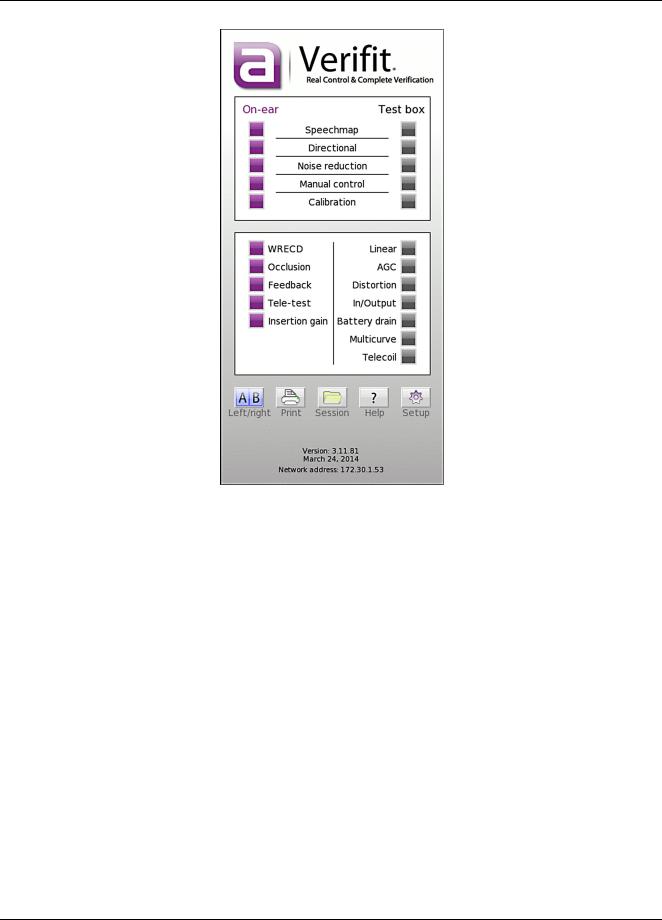
The Verifit is operated with a USB mouse (included) or a keyboard (not included) to select icons and menu items, operate on-screen buttons and to enter audiometric data. Upon starting the Verifit presents the home menu for accessing all tests and major functions. To see the home menu at any time, right click the mouse.
To activate an on-screen icon or button, or to select an item from a menu, use the mouse to place the screen pointer over the icon, button or menu item and left click. To enter a data point on a chart, such as an audiogram, place the screen pointer over the desired point on the chart and left click. To move the data point, place the screen pointer near the new location and left click. To delete a data point, place the screen pointer on the data point and left click. To summon a cursor on a graph, place the screen pointer on the graph and left click, then navigate to the point you want to identify; left click again to hide the cursor. The scroll wheel may be used to traverse the Help contents, multiple Help pages or long menu lists. Note that mouse speed can be changed by
clicking  and [Display].
28
Verifit®User's Guide Version 4.2 © June 2015
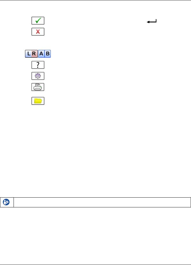
The functions of the screen icons and connected keyboard keys are explained in the following table:
29
Verifit®User's Guide Version 4.2 © June 2015
Screen icon |
Function |
Keyboard |
|
Continue. Proceed from current state |
|
|
|
|
|
Cancel. Revert to previous state |
[Esc] |
|
|
|
|
Show menu of all available tests and |
[F3] |
|
functions (mouse right click) |
|
|
|
|
|
Switch between Left/Right on-ear data or |
[F5] |
|
switch between A/B test box data |
|
|
|
|
|
Show on-line help |
[F1] |
|
|
|
|
Show the setup menu |
[F2] |
|
|
|
|
Print screen to an external printer or a file |
[Print Screen] |
|
|
|
|
Show menu for erasing data or exchanging |
[F4] |
|
data with network files or USB memory |
|
|
|
|
|
|
|
|
Position the screen pointer over the icon, |
[Arrow keys] |
|
button or menu item |
|
|
|
|
|
Activate a screen icon or button, or select an |
[Enter] on numeric |
|
item from a menu (mouse left click) |
keypad |
|
Accept text or numbers typed into any text |
[Enter] on numeric |
|
entry field. |
keypad |
Network connection
The Verifit includes two options for connecting to a computer network, either through the built-in wireless networking feature, or through an external wired connection. The built-in wireless networking feature requires no additional attachments to the Verifit. The external wired connection requires inserting a standard network cable into the network connection on the rear of the display unit, as illustrated in the figure below. You can choose between either the wireless or wired network connection through the software user interface, as described in the section Networking.
Failure to follow operating instructions could place the user or operator at risk.
30
Loading...