

Audioscan Verifit
User's Guide 4.2
© June 2015
®

Table of Contents
1 About Verifit..........................................................................................................................................................................6
Product description...............................................................................................................................................................6
Accessories.........................................................................................................................................................................12
Associated items and supplies............................................................................................................................................13
SAFETY WARNINGS and NOTICES..............................................................................................................................13
Environmental safety..........................................................................................................................................................14
Declaration of Electromagnetic Compatibility (EMC).....................................................................................................14
Warranty, Trademarks, Acknowledgments.......................................................................................................................15
EC Declaration of Conformity...........................................................................................................................................17
Electronic User’s Guide.....................................................................................................................................................18
How to Avoid Undesirable Side Effects............................................................................................................................18
2 Getting Started.....................................................................................................................................................................20
Office setups.......................................................................................................................................................................20
Unpacking and connecting.................................................................................................................................................20
Microphone connection......................................................................................................................................................21
General care instructions....................................................................................................................................................23
Microphone care.................................................................................................................................................................24
Mouse and keyboard...........................................................................................................................................................24
Monitor headphones...........................................................................................................................................................24
External peripherals............................................................................................................................................................26
3 General Operation................................................................................................................................................................28
Switching ON/OFF.............................................................................................................................................................28
Input device operation........................................................................................................................................................28
Network connection............................................................................................................................................................30
Printer connection...............................................................................................................................................................31
Menus, lists and buttons.....................................................................................................................................................32
Screen messages and Help.................................................................................................................................................32
Software updating...............................................................................................................................................................32
4 General Setup.......................................................................................................................................................................34
Date and time setup............................................................................................................................................................34
Display settings...................................................................................................................................................................34
Saving test setup.................................................................................................................................................................34
5 On-Ear Measures - Setup.....................................................................................................................................................36
External sound-field speaker setup....................................................................................................................................36
On-ear calibration facts......................................................................................................................................................37
Calibration of on-ear probe microphone............................................................................................................................37
Calibration check for probe module..................................................................................................................................39
Max TM SPL setup............................................................................................................................................................40
ABR nHL to eHL setup......................................................................................................................................................40
Positioning the client..........................................................................................................................................................40
Positioning the probe tube..................................................................................................................................................41
6 On-Ear Measures Screen Setup...........................................................................................................................................43
On-ear single or dual view.................................................................................................................................................43
Graph, table or 2cc target format.......................................................................................................................................43
SPL or HL scale..................................................................................................................................................................43
Hide or show on-ear curves................................................................................................................................................43
7 Speechmap...........................................................................................................................................................................45
Speechmap facts.................................................................................................................................................................45
DSL 5.0 in Speechmap.......................................................................................................................................................45
NAL-NL1 in Speechmap....................................................................................................................................................46
NAL-NL2 in Speechmap....................................................................................................................................................46
Camfit in Speechmap.........................................................................................................................................................47
Using Speechmap...............................................................................................................................................................47
Speechmap Setup................................................................................................................................................................47
Screen tour - unaided screen..............................................................................................................................................49
Screen tour - aided screen..................................................................................................................................................50

Verifit®User's Guide Version 4.2 © June 2015
On-ear or Test box mode....................................................................................................................................................50
SII calculation in Speechmap.............................................................................................................................................51
Using custom stimuli in Speechmap..................................................................................................................................51
Creating WAV files for Speechmap..................................................................................................................................53
8 Speechmap Fitting Procedures............................................................................................................................................55
Speechmap screen choices.................................................................................................................................................55
Data entry...........................................................................................................................................................................57
Fitting to targets for soft speech.........................................................................................................................................57
Fitting to targets for average speech .................................................................................................................................58
Adjusting the Maximum Output Level..............................................................................................................................59
Open fittings in Speechmap...............................................................................................................................................60
Verifying Frequency Compression/ Frequency-Lowering Hearing Instruments in Speechmap......................................61
Binaural fitting in Speechmap...........................................................................................................................................62
CROS fitting in Speechmap...............................................................................................................................................63
T-Loop fitting and verification in Speechmap..................................................................................................................64
Tele-test fitting and verification in Speechmap................................................................................................................65
FM fitting and verification.................................................................................................................................................66
How to Verify with Calibrated 'S' and 'SH' Stimuli..........................................................................................................66
9 Speechmap Technical Details..............................................................................................................................................68
Wideband measurements in Speechmap............................................................................................................................68
Speechmap stimuli.............................................................................................................................................................68
Stimulus spectra..................................................................................................................................................................69
Microphone location effects...............................................................................................................................................70
Deep insertion compensation.............................................................................................................................................70
Speech signal analysis........................................................................................................................................................71
10 On-Ear Instrument Measures.............................................................................................................................................72
On-ear directional test overview........................................................................................................................................72
On-ear directional testing...................................................................................................................................................72
On-ear feedback test...........................................................................................................................................................73
On-ear noise reduction test.................................................................................................................................................73
On-ear manual control........................................................................................................................................................74
Sound level meter using on-ear microphones....................................................................................................................74
11 WRECD measurement.......................................................................................................................................................76
Calibration of WRECD Transducer...................................................................................................................................76
Measure WRECD ..............................................................................................................................................................76
WRECD results..................................................................................................................................................................78
WRECD protocols..............................................................................................................................................................78
WRECD facts.....................................................................................................................................................................80
12 Occlusion Effect Test.........................................................................................................................................................81
Occlusion effect measurement...........................................................................................................................................81
13 Sensory loss simulator.......................................................................................................................................................82
Sensory loss simulator description.....................................................................................................................................82
Sensory loss simulator operation.......................................................................................................................................82
14 Insertion Gain.....................................................................................................................................................................84
Insertion gain in SPL..........................................................................................................................................................84
Insertion gain in HL...........................................................................................................................................................85
Audiometric data entry.......................................................................................................................................................86
REUR measurement procedure..........................................................................................................................................87
REAR measurement procedure..........................................................................................................................................88
SII calculation in Insertion gain.........................................................................................................................................88
CROS fitting using Insertion gain......................................................................................................................................89
15 Test Box Measures - Setup................................................................................................................................................91
3

Verifit®User's Guide Version 4.2 © June 2015
Test box screen...................................................................................................................................................................91
Format.................................................................................................................................................................................93
Scale....................................................................................................................................................................................93
Hide or Show test box curves.............................................................................................................................................93
ANSI test frequencies.........................................................................................................................................................94
Test box calibration facts...................................................................................................................................................95
Calibrating test box reference microphone........................................................................................................................95
Calibration check for coupler microphone........................................................................................................................96
Coupling for binaural/wideband tests................................................................................................................................96
Positioning HI for binaural/wideband tests........................................................................................................................97
Coupling for ANSI tests.....................................................................................................................................................98
Positioning HI for ANSI tests............................................................................................................................................99
16 ANSI Hearing Aid Tests..................................................................................................................................................101
ANSI S3.22-2003 facts.....................................................................................................................................................101
ANSI 2003 Linear and AGC tests....................................................................................................................................101
ANSI test results...............................................................................................................................................................102
ANSI input-output curves................................................................................................................................................102
ANSI telecoil terminology...............................................................................................................................................103
ANSI telephone simulator (TMFS) test...........................................................................................................................103
ANSI test loop test............................................................................................................................................................104
Telecoil test results...........................................................................................................................................................106
17 Other Test Box Measures................................................................................................................................................107
Harmonic distortion..........................................................................................................................................................107
Noise reduction.................................................................................................................................................................107
Directional function test...................................................................................................................................................108
Directional ITE positioning..............................................................................................................................................108
Directional BTE positioning............................................................................................................................................109
Test box directional procedure.........................................................................................................................................110
Multicurve procedure.......................................................................................................................................................111
Multicurve results.............................................................................................................................................................111
Spectral analysis in Multicurve........................................................................................................................................112
Battery drain test..............................................................................................................................................................112
Manual control procedure................................................................................................................................................113
Sound level meter using manual control.........................................................................................................................114
18 Networking.......................................................................................................................................................................116
Networking standards.......................................................................................................................................................116
Network setup...................................................................................................................................................................116
Remote Operation.............................................................................................................................................................118
Changing the Remote Operation settings........................................................................................................................118
NOAH Service Port..........................................................................................................................................................119
Changing the NOAH service port....................................................................................................................................119
Testing the NOAH service port........................................................................................................................................120
Web Service Port..............................................................................................................................................................120
19 Single Computer Connection...........................................................................................................................................122
Automatic connection (recommended)............................................................................................................................122
Static connection..............................................................................................................................................................122
20 Printing and Storing Results............................................................................................................................................124
Storing data in NOAH......................................................................................................................................................124
Printing results..................................................................................................................................................................124
Printing setup....................................................................................................................................................................124
Printer connection.............................................................................................................................................................125
Printer types......................................................................................................................................................................126
4

Verifit®User's Guide Version 4.2 © June 2015
HP printer..........................................................................................................................................................................126
Custom printer..................................................................................................................................................................126
File output.........................................................................................................................................................................127
Page setup.........................................................................................................................................................................127
Windows-shared printers and folders...............................................................................................................................129
Network printer.................................................................................................................................................................131
Web browser screen capture............................................................................................................................................131
Session setup.....................................................................................................................................................................132
Storing and restoring session files....................................................................................................................................133
21 Troubleshooting...............................................................................................................................................................135
Self test failures................................................................................................................................................................135
Initialize Function............................................................................................................................................................135
Inconsistent levels in speech stimulus.............................................................................................................................136
Test box high distortion or noise......................................................................................................................................136
Test box curves inconsistent............................................................................................................................................136
Test box curves differ from specifications......................................................................................................................136
Test box speaker overdriven............................................................................................................................................137
No test box reference mic. detected.................................................................................................................................137
Invalid test box calibration...............................................................................................................................................137
Unable to calibrate test box microphone.........................................................................................................................137
No on-ear ref. mic. detected.............................................................................................................................................138
Invalid on-ear calibration.................................................................................................................................................138
Unable to calibrate on-ear microphone............................................................................................................................138
Sound-field speaker overdriven.......................................................................................................................................139
Invalid binaural equalization............................................................................................................................................139
22 Technical Specifications..................................................................................................................................................140
23 Glossary............................................................................................................................................................................147
24 References........................................................................................................................................................................152
25 Appendix 1.......................................................................................................................................................................155
Manufacturer Disclosure Statement for Medical Device Security.................................................................................155
5
Verifit®User's Guide Version 4.2 © June 2015
1 About Verifit
This section provides a listing of features new in this software release, describes the Audioscan Verifit, provides
contact, warranty and trademark information, safety warnings and notices and instructions for accessing the
electronic User’s Guide.
Note that the User's Guide may be viewed on the Verifit at any time by pressing <Help>. (For long Help pages,
use the mouse to switch between the Help index and the Help page, and to scroll through the page).
Product description
The Verifit is a hearing instrument analyzer intended to be used by hearing care professionals such as
audiologists and hearing instrument specialists to verify the electro-acoustic performance of a hearing
instrument connected to a standard earphone coupler or while worn on the ear of the end user. The Verifit is a
Programmable Electrical Medical System (PEMS). The system consists of a real-ear measurement (REM)
display unit, a hearing instrument test (HIT) acoustically-treated binaural test box, and numerous attachable
components and accessories:
Display Unit
A real-ear measurement (REM) display unit housing a flatpanel LCD high resolution display, signal generation,
measurement and control electronics, and two sound-field
loudspeakers.
On the sides of the display unit, there are connections for:
1.monitor headphones on the lower right side
2.a USB jack on the lower left side (for the
Audioscan update stick, for example)
3.magnet mounts on both sides of the display unit,
approximately 8cm (3 in.) down from the top (this
is where you store the probe dock when not in use)
On the rear of the display unit, there are connections for:
1.an external monitor
2.a network connection
3.external loudspeakers
4.power supply
5.test box cable
6.probe dock cable
7.four USB jacks (for a keyboard, printer, and a
mouse) - the USB stick for the mouse is already
inserted into one of these USB jacks
The following components are shipped with the display unit
6
Verifit®User's Guide Version 4.2 © June 2015
Component Description
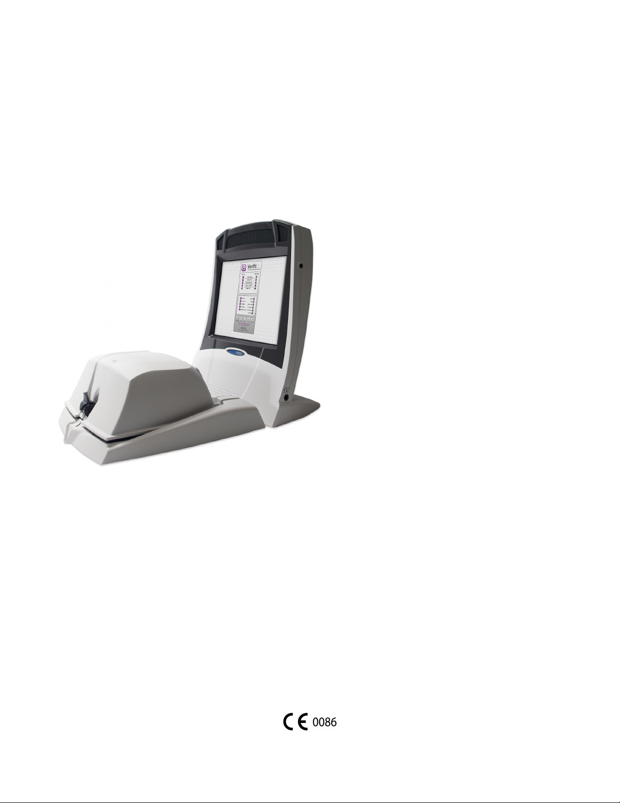
External power supply connected to a hospital grade power
cord (in North America) or a country-specific power cord
(international markets) .
Electrical supply input requirement: 100 – 240 Vac
47 – 63 Hz 1.35 – 0.53 A
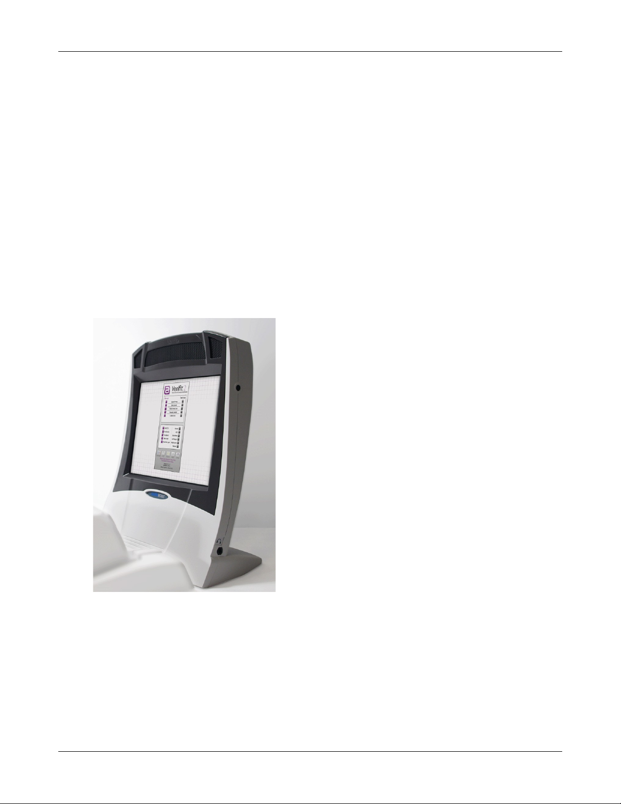
Probe dock, shown here with 2 probe microphones (which
nest into, and are connected to, the probe dock). This is the
configuration of these components when they are shipped to
you.
The probe dock has connections for the 2 probe microphones,
the WRECD transducer, and the tele-test handset. It is intended
that the probe dock clips near to or on the patient.
There is a probe cables adjust clip on the probe microphone
cables that allows you to adjust the probe microphones flat
against the client's cheek
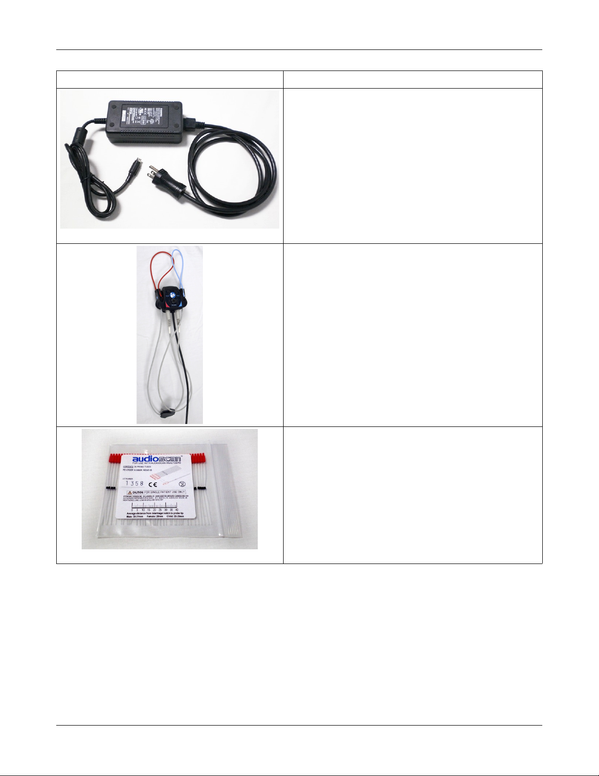
Probe tubes, package of 36
7

Verifit®User's Guide Version 4.2 © June 2015
Component Description
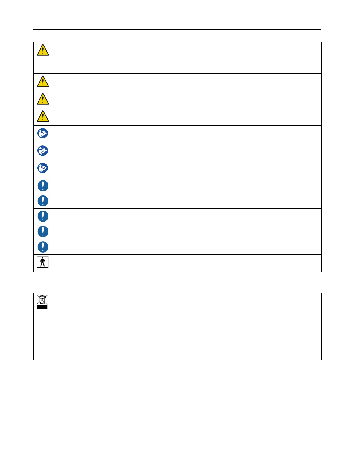
WRECD transducer used to measure the wideband real-ear
to coupler difference (WRECD) useful in estimating the sound
level produced in an individual ear from measurements in a
coupler
Foam eartips for measuring WRECD. The package contains:
•Qty 5 ER3-14A adult foam eartips
•Qty 5 ER3-14B pediatric foam eartips
Wireless mouse
Monitor headphones provided with 2 detachable (detachable
from the headphone) cables, each having 3.5mm stereo plugs
on each end. The cables are 130cm (51 in.) and 365cm (12
feet) in length
a 3.5cm to 1/4-inch adapter plug is also provided (to connect to
the 1/4-inch headphone jack on the display unit)
8
Verifit®User's Guide Version 4.2 © June 2015
Component Description
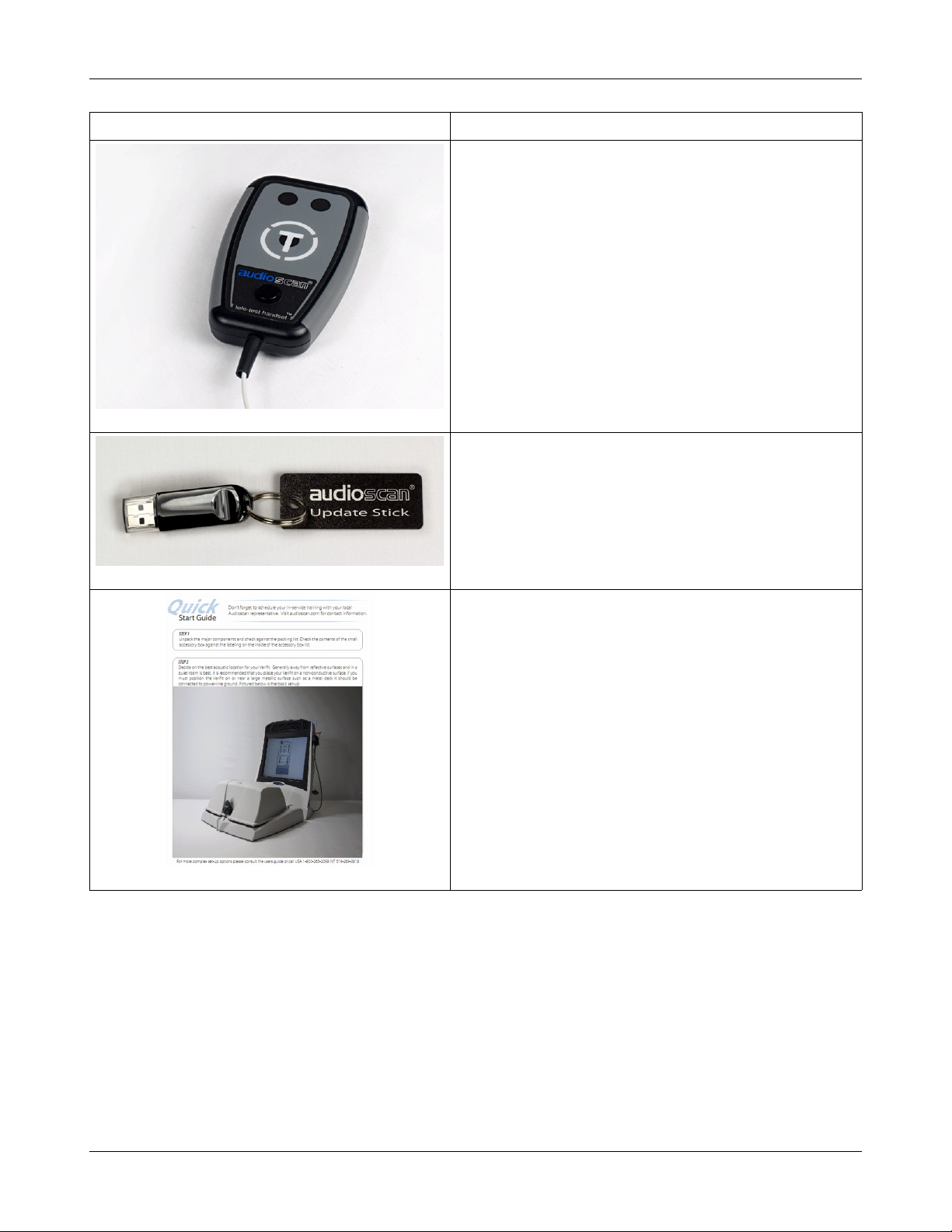
Tele-test handset used to provide an inductive stimulus for
simulating operation with a telephone in Speechmap and for
performing ANSI TMFS test.
Audioscan update USB stick
Quickstart setup guide
9

Verifit®User's Guide Version 4.2 © June 2015
Test Box
Hearing instrument test (HIT) acoustically-treated
binaural test box which houses a telecoil test loop,
3 loudspeakers and connections for:
•two reference microphones,
•binaural coupler microphone
•battery pill substitutes
The following components are shipped with the test box
Component Description
Test box cable to connect the test box to the display unit
Binaural coupler microphone for the purpose of
measuring the sound level produced in the standard coupler
by a hearing instrument
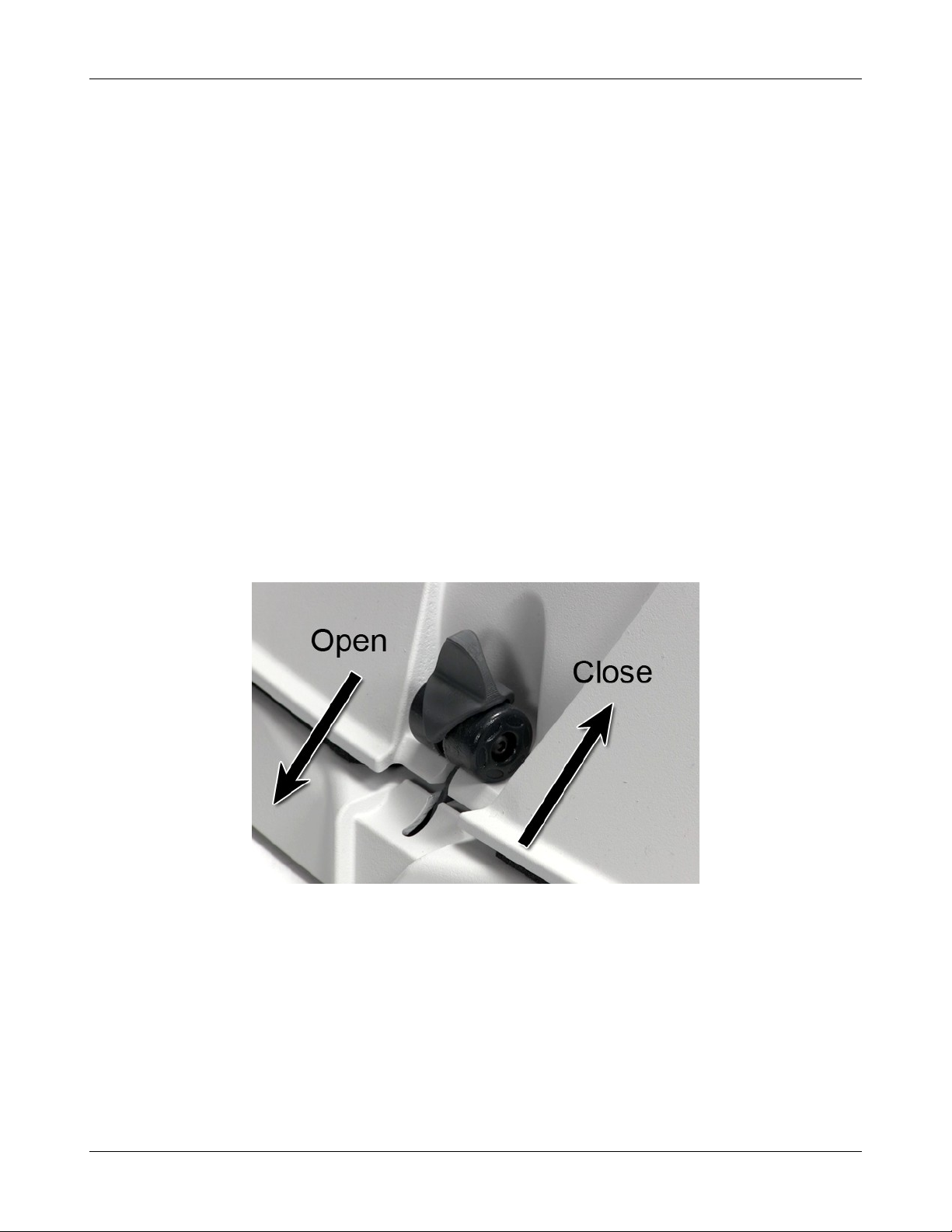
Testbox reference microphones for controlling the signal
from the loudspeakers (2)
10
Verifit®User's Guide Version 4.2 © June 2015
Component Description
0.4cc wideband couplers that are attached to the binaural
coupler microphone
HA-1 (ITE) 2cc coupler (1)
HA-2 (BTE) 2cc coupler (1)
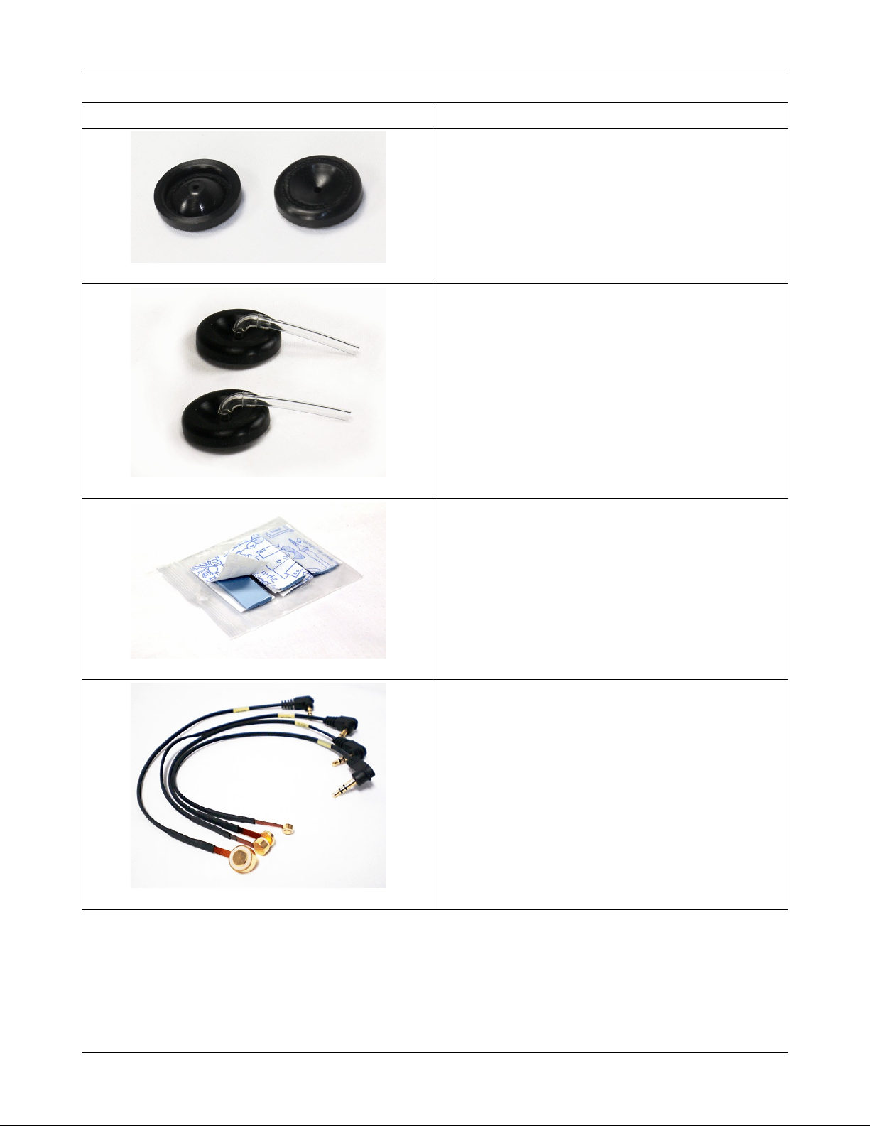
Hearing instrument stabilizers, attached to the 0.4cc
couplers to support BTE-style instruments
11
Verifit®User's Guide Version 4.2 © June 2015
Component Description
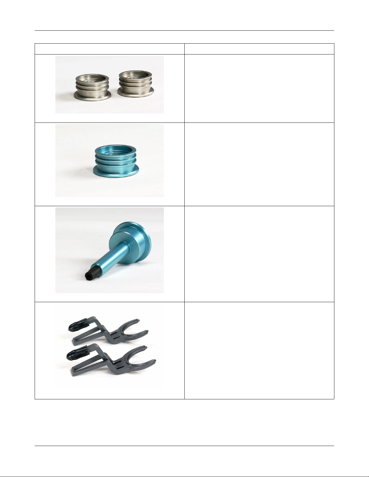
TRIC adapters (Thin-tube, Receiver In Canal) designed
for use with 0.4cc and HA-1 (ITE) 2cc couplers
Earmold substitutes (HA-4 tubing) inserted in a second
set of TRIC adapters to allow BTE instruments to be
coupled to the 0.4cc coupler without earmold
Putty, to attach custom hearing instruments and earmolds
to the coupler 0.4cc and HA-1 (ITE) 2cc couplers
Battery pill substitutes, kit consisting of:
1 - E352 Battery Size #10A
1 - E353 Battery Size #13A
1 - E354 Battery Size #312
1 - E355 Battery Size #675
Accessories
RE367-36 probe tubes for single patient use (36 per bag)
12

Verifit®User's Guide Version 4.2 © June 2015
ER3-14A and ER3-14B foam eartips (package containing 5 of each)
Associated items and supplies
VA-111 External speaker with folding stand
VA-131 Microphone extension cable (90cm / 36 in.) for use with binaural coupler microphone
VA-134 Probe dock extension cable (375cm / 12 ft.) for use with the probe dock
VA-201 NOAH® module allows a networked PC running NOAH to exchange data with Audioscan analyzers
RE-790 Binaural coupler microphone adapter for use with QUEST CA22 calibrator (1-1/8 in.)
RE-791 Binaural coupler microphone adapter for use with QUEST QC 10/20 calibrators (1 in.)
SAFETY WARNINGS and NOTICES
For purposes of IEC 60601-1, this product is Class I with Type BF applied parts. The applied parts are:
1.Probe tube
2.Foam eartip
3.Probe microphone
This device complies with Part 15 of the FCC Rules. Operation is subject to the following two conditions:
(1) this device may not cause harmful interference, and (2) this device must accept any interference
received, including interference that may cause undesired operation
This Class A digital apparatus complies with Canadian ICES-003
This symbol on the product is a WARNING describing a foreseen risk
WARNING: To avoid the risk of electrical shock, use only the power supply and power cord supplied with
the Verifit and connect it only to a grounded (protectively earthed) electrical outlet.
WARNING: To allow electrical power to be rapidly disconnected in the event of an emergency, position the
power supply in an accessible location so that the power cord may be quickly disconnected.
WARNING: To avoid the risk of electrical shock, any line-powered peripheral equipment connected to this
product must comply with UL/IEC 60601-1 OR comply with UL or IEC and ISO safety standards for such
equipment AND a) be operated from an isolating transformer complying with UL/IEC 60601-1 OR b) be kept
at least 1.8m (6 ft.) from the patient.
WARNING: This equipment is not suitable for use in an oxygen-rich environment or in the presence of
flammable anesthetic mixtures with air or with oxygen or nitrous oxide.
WARNING: To ensure proper operation of this product, no modification of this equipment is permitted
WARNING: Probe tubes are for single-patient use only. Care is required when sliding the probe tube into the
ear canal. Be careful not to advance the probe tube further into the ear canal when inserting an earmold or
custom hearing instrument into the ear or when inserting the foam tip into the ear
WARNING: Foam eartips are for single-patient use only
13
Verifit®User's Guide Version 4.2 © June 2015
WARNING: To ensure that the operation of this product is not affected by EMC emissions from other
products, this product should not be used adjacent to or stacked on other equipment. If this is necessary, its
operation should be verified as normal in this configuration. Portable and mobile RF communications
equipment can affect the performance of this product
WARNING: To reduce the risk of contamination, hearing instruments should be clean before putty is applied
and putty should be replaced frequently
WARNING: The included magnet may effect some medical or electronic devices. Keep magnet at least 5cm
(2in.) from implantable devices and other magnetically sensitive devices.
WARNING: Keep magnet out of reach of children and pets. If a magnet is swallowed seek immediate
medical attention.
This symbol on the product is a WARNING that failure to follow instructions in this part of the User’s and/or
Quick Start Guides could place the operator or patient at risk.
Failure to follow the operating instructions for connecting to a network, a local printer, a keyboard, or an
external monitor could place the operator at risk
Failure to follow the operating instructions for connecting the monitor headphones, the mouse, or the
Audioscan update stick could place the operator at risk
This symbol on the product is a WARNING describing a required action
Use only an approved test box cable to connect the test box and the display unit
The test box can only be connected to the display unit
The VF2 power supply can only be connected to the mains using the supplied power cord
The probe dock can only be connected to the display unit
This symbol on the product means that the parts applied to the patient meet the safety requirements of IEC
60601-1 for type BF isolated (floating) applied parts
Environmental safety
This symbol on the product means that this product is not to be disposed of in unsorted municipal waste
because electrical and electronic waste may contain hazardous substances which could endanger the
environment and human health.
This product and its associated items must be disposed of in accordance with local disposal regulations for electrical
and electronic waste. Consult your local waste disposal authority regarding applicable regulations.
The probe tubes (used with the probe microphones) and the foam eartips (used with the WRECD transducer) are for
single patient use. After use, they may be disposed of in unsorted municipal waste or as required by your facility's waste
management policy.
Declaration of Electromagnetic Compatibility (EMC)
Medical electrical equipment needs special precautions regarding EMC and needs to be installed and put into
service according to the following information:
• The Verifit should not be used adjacent to or stacked on other equipment. If this is necessary, its operation
14

Verifit®User's Guide Version 4.2 © June 2015
should be verified as normal in this configuration.
• Portable and mobile RF communications equipment can affect medical electrical equipment and may affect
the performance of the Verifit.
• Performance degradation due to electromagnetic disturbances (including electrostatic discharge) is
considered normal and acceptable
The compliances listed in the following table are met with the supplied WRECD transducer, binaural coupler
microphone, probe microphones, reference microphones, monitor headphones, mouse, and a keyboard, all of
which are connected, and with unterminated speaker cables (2), USB cables (5), Ethernet cable, test box cable,
and HDMI display cable connected. The connection of other devices may result in increased emissions.
Guidance and manufacturer’s declaration - electromagnetic emissions
The Verifit is intended for use in the electromagnetic environment specified below. The user of the Verifit should
assure that it is used in such an environment.
Emissions test Compliance Electromagnetic environment - guidance
RF emissions
CISPR 11
RF emissions
CISPR 11
Harmonic emissions
IEC 61000-3-2
Voltage fluctuations/ flicker
emissions
IEC 61000-3-3
Group 1
Class A
Class A
Complies
The Verifit uses RF energy only for internal function.
Therefore RF emissions are very low and not likely to
cause any interference in nearby electronic equipment.
The Verifit is suitable for use in all establishments
other than domestic and those directly connected to
the public low-voltage power supply network that
supplies buildings used for domestic purposes.
Warranty, Trademarks, Acknowledgments
The Audioscan Verifit is manufactured by Etymonic Design Inc., 20 Ludwig St., Dorchester, Ontario, Canada,
N0L 1G4. Web site www.audioscan.com.
Phone: 800-265-2093 (USA only); 519-268-3313 Fax: 519-268-3256
Email: info@audioscan.com or service@audioscan.com
The authorized representative for this product in the European Community is:
P.C. Werth, Audiology House, 45 Nightingale Lane, London, UK, SW12 8SP.
Phone: +44 (0) 181-675 5151 Fax +44 (0) 181-675 7577.
Warranty: The Verifit is warranted against defects for two years from date of purchase. Within this period, it
will be repaired without charge for parts, labor or return shipping when returned prepaid to your authorized
Audioscan service agent. This warranty does not apply to equipment that, in our sole judgment, has been subject
to misuse, or unauthorized alteration or repair.
Trademarks:
Audioscan, Speechmap, and Verifit are registered trademarks of Etymonic Design Inc. DSL is a registered
trademark of Western University. All rights reserved. HP LASERJET is a registered trademark of HewlettPackard Company. NOAH is a registered trademark of the Hearing Instrument Manufacturer's Software
Association. QUEST is a trademark of Quest Technologies Inc. PostScript is a registered trademark of Adobe
15

Verifit®User's Guide Version 4.2 © June 2015
Systems, Inc.
Acknowledgments:
DSL 5.0 is used under license from Western University which is solely responsible for its content. We
acknowledge the support received from past and present staff at the National Centre for Audiology at Western
University in implementing the DSL method.
CAMFIT is used under license from Prof. Brian C.J. Moore, University of Cambridge, UK. We are indebted to
the University of Memphis hearing instrument Research Laboratory for permission to use some of their recorded
speech material.
NAL-NL1 is used under license from the National Acoustics Laboratories, Australia.
NAL-NL2 is used under license from Hearworks Pty Ltd, Australia.
Software licenses:
Audioscan distributes selected software components under various open source licenses. These licenses
generally give you the right to copy and change the affected component's software source code. For details, see
the license files distributed with the software, or contact Audioscan.
16

Verifit®User's Guide Version 4.2 © June 2015
EC Declaration of Conformity
17

Verifit®User's Guide Version 4.2 © June 2015
Electronic User’s Guide
You can download the current User's Guide directly from www.audioscan.com. A printable User's Guide is also
provided with each new instrument and each software update. A .pdf file viewer, such as Acrobat Reader (5.0
or higher) or Foxit Reader is required to view the User’s Guide. Except for some additional reference material,
the information in the User's Guide is available to you on the Verifit at any time by right-clicking and selecting
.
A printable User’s Guide is on the Audioscan update stick supplied with the instrument. This User's Guide will
be updated each time you download new software from www.audioscan.com to the Audioscan update stick.
To view the User's Guide:
1. Insert the Audioscan update stick into a USB port on your PC.
2. If your PC does not open the Audioscan update stick automatically, select My Computer, then the
Removable Disk drive (usually E or F).
3. Double click the User_Guide folder to open it.
4. Double click the English folder and copy the Verifit Users Guide.pdf file to an appropriate location on your
PC. Double click on the file to open it for viewing.
When you have finished copying the file from the Audioscan update stick, click on the safely remove icon on
your PC and remove the Audioscan update stick when you are notified that it is safe to do so.
STORE THE AUDIOSCAN UPDATE STICK IN A SAFE PLACE. YOU WILL REQUIRE IT TO INSTALL
FUTURE SOFTWARE UPDATES.
How to Avoid Undesirable Side Effects
During the development of the hearing instrument analyzer, Audioscan performed a rigorous Risk Assessment to
identify any undesirable side effects that a user could be exposed to during the use of the Verifit, and
incorporated numerous risk reduction design elements into the Verifit to minimize the risk to users and patients.
Following are the actions which a user should take to ensure that these risk control measures continue to be
effective
Loud Sounds
The Verifit is designed to produce sound pressure levels as high as 85 dB at the probe reference
microphone. Exposure to these levels for more than 7 hours can produce hearing damage. When such levels are
amplified by a hearing instrument, the level in the ear canal will be determined by the settings of the hearing
instrument but may reach levels that can produce hearing damage in less than 30 seconds. To avoid this
possibility,
a) Hearing instruments should be adjusted to limit sound pressure levels to safe levels
b) The maximum TM SPL setting (see Max TM SPL Setup) should be used to terminate tests if an unsafe level
is detected in the ear canal
c) Test levels should be limited to 70 dB SPL except when necessary to verify the limiting levels of the hearing
instrument, in which case, the test should not last longer than 15 seconds
d) Be aware of the test signal and patient reaction during a test and be prepared to respond to any sign of
discomfort by reducing the SPL setting, switching off the equipment or the hearing instrument, or removing the
patient from the area.
18

Verifit®User's Guide Version 4.2 © June 2015
When using the equipment to measure the WRECD or RECD in small ear canals, it is possible to induce a
hearing loss if the test is allowed to continue for more than 1 hour. Since accurate results can be obtained in less
than 10 seconds, this possibility should never occur in normal practice.
Power and Grounding
This product contains numerous safety features to ensure that the probability of electrical shock is as low as
reasonably practicable. In order to ensure that all of the safety features work optimally you must ensure that the
power cord is plugged into a grounded outlet. Any line-powered peripherals connected to Verifit must comply
with UL/IEC 60601-1 OR comply with UL or IEC or ISO safety standards for such equipment, AND a) be
operated from an isolating transformer complying with UL/IEC 60601-1, OR b) be kept at least 1.8m (6 ft..)
from the patient.
Ear Infection
Probe tubes (used on probe microphones) or foam eartips (used on the WRECD transducer) should not be reused on another patient. There is a possibility of transferring an ear infection to the other patient. Probe tubes
and foam eartips are for single-patient use only. Probe tubes can be wiped with alcohol wipes for re-use with the
same patient, but must not be used with multiple patients. Do not attempt to clean or re-use the foam eartips.
To avoid cross-contamination between patients, hearing instruments should be cleaned with disinfectant
towlettes (e.g., audiowipes) prior to being puttied into a coupler, and the putty should be replaced if it becomes
soiled.
Ear Canal Discomfort
An otoscopic examination should always be performed prior to inserting a probe tube into the ear canal to
ensure that it is healthy and free of obstructions. Care is needed when inserting probe tubes into the ear canal.
Although the probe tubes are made of soft, flexible material specially designed for this application, it is possible
to scrape the ear canal or touch the eardrum causing brief discomfort. You should carefully follow the
instructions in Positioning the probe tube section of this User’s Guide.
Implantable Electronic Device
The tele-test handset comes with a small magnet attached. This included magnet may affect some medical or
electronic devices. Keep the magnet more than 5cm (2 in.) from implantable devices and other magnetically
sensitive devices.
All pacemakers respond to a magnet by switching to an asynchronous pacing mode at a programmed
atrioventricular (AV) delay and a fixed magnet rate depending on the manufacturer, device model, and the status
of the battery. The programmed mode DDD switches to DOO, VVI switches to VOO, and AAI switches to
AOO. The rate response feature is switched to 'OFF' on magnet application in pacemakers. In biventricular
pacemakers, both the right and left ventricles continue to be paced in the above modes with magnet application
so long as the device is at or above ERI. However, from below ERI voltage, this response is unpredictable.
In general, magnet application suspends anti-tachycardia therapy without any effect on the pacing mode.
Implantable cardioverter defibrillator models from St. Jude Medical and Boston Scientific, however, have
additional programmable features to ignore the magnet or respond differently to a magnet. All biventricular
ICDs behave like any other ICDs of the corresponding manufacturer. In most cases, anti-tachycardia therapy
resumes with removal of the magnet. However, in some instances, magnet removal may or may not re-enable
anti-tachycardia therapy. Specific care should be exercised in Guidant/Boston Scientific ICDs since some of the
older models are equipped with circuitry that enables the magnet to permanently programme the antitachycardia therapy to 'OFF'. In addition, magnet application on Sorin ICDs changes the pacing rate without
altering the pacing mode. Rate response of ICDs is not influenced by magnet application.
19
Verifit®User's Guide Version 4.2 © June 2015
2 Getting Started
This section provides instructions for unpacking the Verifit and connecting various components and associated
items.
Office setups
1. Conventional. In the standard setup the Verifit display unit and test box are placed either side by side or colinear (test box in front) on the same surface. The distance between them is only limited by the test box cable
that connects them. If an external speaker is not being used, the display unit should be positioned so that a client
will be less than 100cm (3 ft.) from the speakers above the display (see also, Positioning the client).
2. Wall mounted. The display unit can be mounted on a wall bracket with a standard VESA mount. Use care to
route cables appropriately to avoid accidental damage and avoid mounting the Verifit where it will protrude into
walkways or other thoroughfares. Screws supplied with the Verifit should be kept installed when not using a
wall mount. For wall mounting longer screws will be necessary. Length will depend on thickness of mount.
IMPORTANT: Please ensure that any screws used do not exceed a length which would cause them to penetrate
the Verifit rear panel to a depth greater than 16mm (5/8").
3. Remote operation. As the Verifit can be run from your PC desktop in On-top mode, more unconventional
office setups are possible as the display unit does not necessarily need to be in front of the practicioner (see also,
Networking).
Unpacking and connecting
1. Carefully unpack the two parts of the Verifit and check the contents of the shipping box against the enclosed
packing list. Note that some parts may be packed inside the test chamber.
2. Locate the included wireless mouse and turn it on using the switch on the underside. The wireless receiver is
already connected to the Verifit.
3. Connect the test box via the test chamber cable to the rear of the main display unit. The cable can be routed
under the display unit to the test chamber if the test chamber will be used in front to the display unit. Note:
all on-ear functions will operate without the test box connected to the display unit.
20
Verifit®User's Guide Version 4.2 © June 2015
Text box cable provided uses HDMI connector, but is distinguished by a diamond-shaped marker at both ends.
IMPORTANT: Use only Audioscan-supplied cables for this purpose.
4. The Verifit can also be connected to an external monitor. Connect a video monitor (HDMI or DVI with
adapter) to the MONITOR connector on the rear connector panel.
Failure to follow operating instructions could place the user or operator at risk.
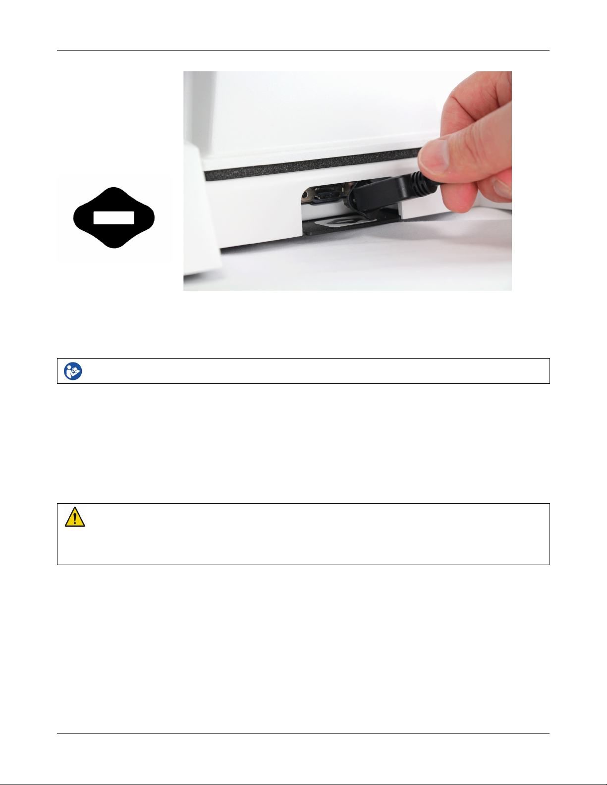
5. Open the lid of the test chamber by using your thumb to roll the rubber roller toward the front of the Verifit.
This is made easier by placing your fingers under the front lip. When sealing the chamber in its closed
position, place your fingers on top of the lid and use your thumb to roll the rubber roller toward the rear of
the Verifit.
6. Connect the Verifit power supply (included) to the power connector on the rear connector panel.
7. Connect the power cord (included) from the Verifit power supply to a GROUNDED electrical outlet. In the
USA and Canada, this outlet should be marked Hospital Grade.
WARNING: To avoid the risk of electrical shock, use only the power supply and power cord supplied with
the Verifit and connect it only to a grounded (protectively earthed) electrical outlet.
WARNING: To allow electrical power to be rapidly disconnected in the event of an emergency, position the
power supply in an accessible location so that the power cord may be quickly disconnected.
Microphone connection
1. Plug the reference microphones and the binaural coupler microphone into the connectors in the test chamber
as shown. The binaural coupler microphone is positioned in the test chamber magnetically.
21

Verifit®User's Guide Version 4.2 © June 2015
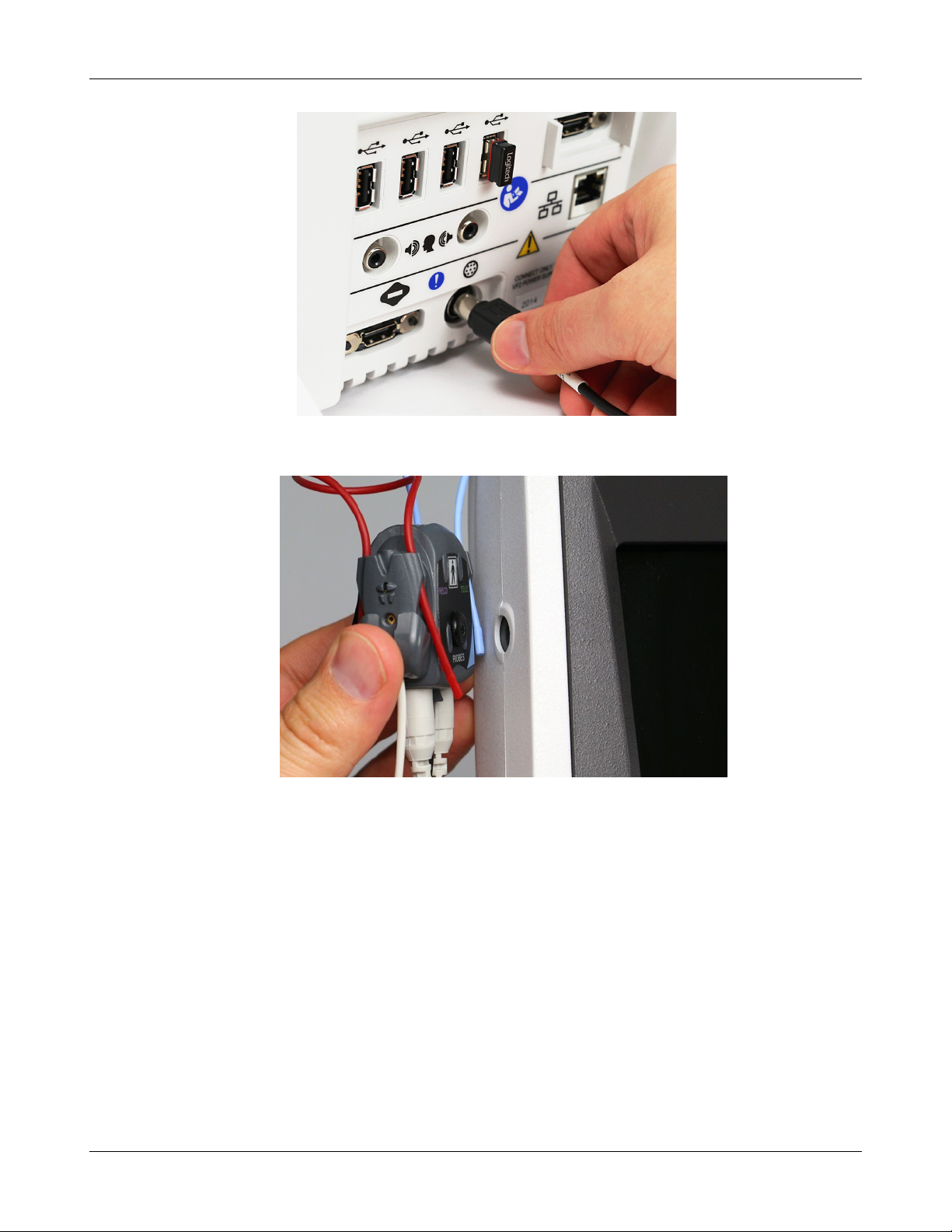
2. Connect the probe microphones to the left (blue) and right (red) connectors on the bottom of the probe dock.
The probe microphone modules should be kept in the probe doc when not in use, positioned with the
reference microphone ports facing outward.
3. Link the probe microphone cables with the probe cables adjust clip as shown above.
4. Connect the 8 pin mini DIN connector of the probe dock to the rear of the main display unit.
22
Verifit®User's Guide Version 4.2 © June 2015
5. The probe dock can be attached to the main display unit via the magnet mount.
NOTE: A coupler microphone extension cable (VA-131) is available from Audioscan. Standard audio extension
cables should not be used. They will substantially increase noise levels.
General care instructions
Probe tubes are for single patient use only. They may be wiped with alcohol wipes for re-use with the same
patient, but must not be used with multiple patients. Attempts at ultrasonic cleaning usually result in cerumen
becoming lodged in the lateral end which causes irreparable damage to the probe microphones.
The case can normally be cleaned/dusted with a damp cloth, however if it is soiled we recommend wiping with
a mild solution of water and detergent, or with alcohol-impregnated wipes deemed safe for use on electronic
equipment. Parts that come into contact with patients (the probe module body, cable, and red and blue lanyards)
23

should be regularly wiped down with alcohol wipes.
Hearing instruments should be cleaned prior to introduction to the test chamber due to the difficulty of sanitizing
the acoustic foam. Custom hearing instruments must be cleaned with disinfectant towlettes (i.e. audiowipes)
prior to placing in the test for this reason and to minimize contamination of the blue putty used with the HA-1
(ITE) coupler. The acoustic foam in the floor of the test chamber is easily removed and should be replaced if
badly worn or soiled. The black rubber TRIC (Thin-tube & Receiver In Canal) adapters may be cleaned with
disinfectant towlettes if they becomes soiled with use.
Audioscan recommends periodic replacement of the blue putty used with the HA-1 coupler to ensure
cleanliness. Both couplers and coupler microphone can be wiped down with alcohol wipes as needed.
Ensure that all safety and usage recommendations on cleaning product packages are followed.
Microphone care
Binaural coupler microphone:
1. DO NOT leave the coupler microphone plugged in when transporting.
2. DO make sure that the couplers are fully connected to the coupler microphone when performing hearing
instrument tests. Coupler leakage can cause feedback and erratic response curves.
3. DO make sure the tubing on the HA-2 (BTE) coupler is free from any cracks/tears.
Verifit®User's Guide Version 4.2 © June 2015
4. DO make sure that any replacement tubing used on the BTE coupler is either obtained from Audioscan, or is
#13 heavy wall earmold tubing exactly 10 mm (.38 inches) in length.
Probe microphone:
Debris can alter the probe module reference microphone calibration and frequency response and can
permanently clog the probe module port.
1. DO NOT reuse probe tubes. Probe tubes can be wiped with alcohol wipes for re-use with the same patient,
but must not be used with multiple patients. Attempts at ultrasonic cleaning usually result in cerumen
becoming lodged in the lateral end which causes irreparable damage to the probe microphones.
2. DO NOT attempt to open or repair the probe microphone. Attempting to repair the probe module may lead
to damage or alteration of the factory calibration.
3. DO keep the probe module and probe tubes in a clean area.
4. DO stow the probe module when not in use or when transporting the Verifit.
Mouse and keyboard
The Verifit may be operated from a mouse or a standard computer keyboard, which may also be used to enter
headers and comments on printouts. A USB mouse or keyboard may be plugged directly into any of the USB
ports provided. See Input device operation.
Monitor headphones
You can use the supplied monitor headphones to listen to the signal from the coupler or the probe microphone.
This is useful for:
1. Listening to the hearing aid to troubleshoot sound quality complaints
2. Listening to the wearer's own voice to troubleshoot occlusion effect complaints
24
Verifit®User's Guide Version 4.2 © June 2015
3. Verifying program settings and their notification beeps
4. Demonstrating hearing aid features to parents, teachers and significant others
5. Making simultaneous comparisons between two hearing instruments
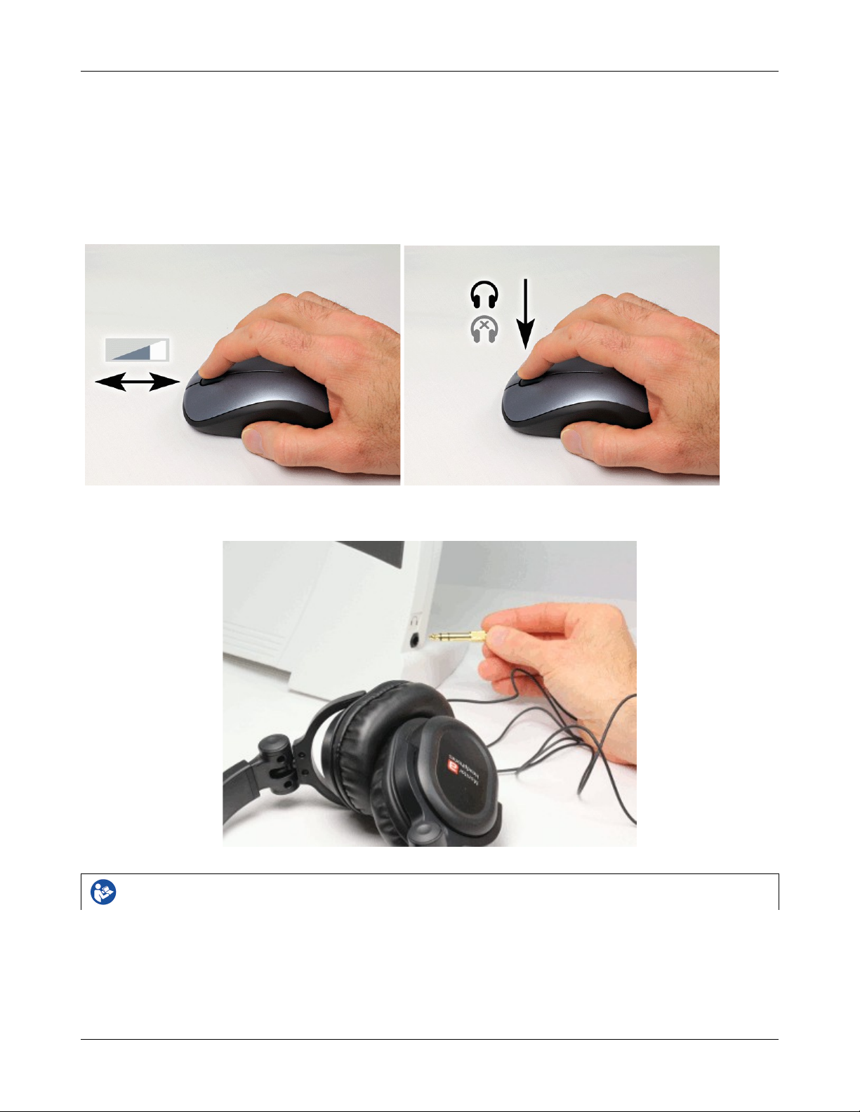
Use the mouse scroll wheel to control the monitor headphone. To adjust the volume, scroll the mouse wheel
forward and backward. To mute the headphone output, click the mouse wheel. To unmute, click the mouse
wheel again.
To connect the monitor headphones, insert the headphone plug into the stereo jack on the lower right-hand side
of the display unit.
Failure to follow operating instructions could place the user or operator at risk.
Most Verifit hearing instrument tests measure the output signal from one microphone. In this common,
monaural case, the monitor headphones present the same signal to both ears, as indicated by the solid black
headphone icon.
In Speechmap Dual View, you have the option of measuring output from both the left and right microphones
simultaneously. When you select L+R, the monitor headphones present the left and right microphone signals to
25
Verifit®User's Guide Version 4.2 © June 2015
the left and right sides of the headphones. You can optionally focus your listening attention by selecting only the
left or right microphone signals. By repeatedly clicking the mouse wheel, you rotate your selection among the
binaural, left-only, right-only and muted headphone presentation options.
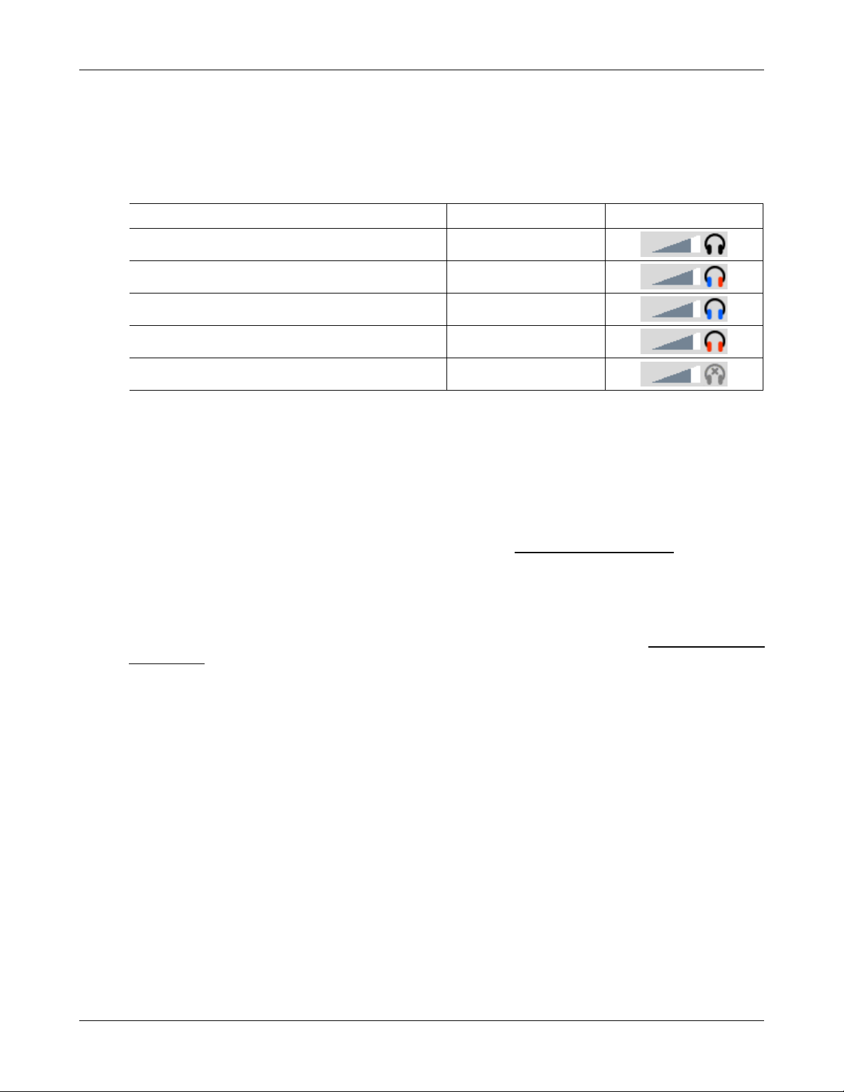
The following table outlines the headphone presentation options and the corresponding microphone signals for
each ear.
Selection Left ear Right ear Presentation
Monaural Active mic Active mic
Binaural Left mic Right mic
Left-only Left mic Left mic
Right-only Right mic Right mic
Mute Off Off
External peripherals
An external video monitor (HDMI or DVI with adapter) may be connected to the HDMI connector on the
rear of the main display unit. The internal display and external monitor will operate simultaneously. The
external monitor must be capable of displaying 1024 x 768 at a refresh rate of 60Hz. Ensure that the
external display is powered up and set to the correct input prior to powering on the Verifit.
An external printer may be connected to one of the USB ports. See Printing and Storing Results for guidance in
selecting a printer model.
Connectors for external front and back sound-field speakers are provided. The VA-111 external speaker with a
multipurpose folding stand is available from Audioscan but any small, non-powered 4 - 8 ohm speaker having
a smooth frequency response and good efficiency may be used. The rear external speaker is automatically
selected when required by a test but the front speaker must first be selected in Setup. See External sound-field
speaker setup
26
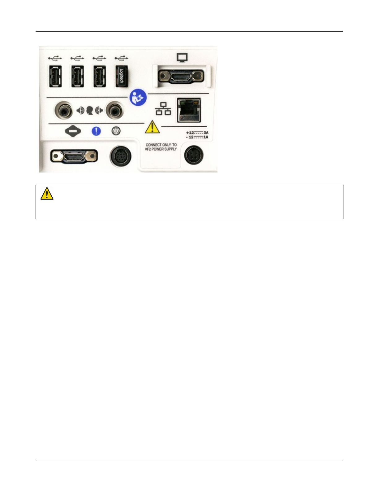
Display unit rear connector panel
WARNING: To avoid the risk of electrical shock, any line-powered peripheral equipment connected to this
product must comply with UL/IEC 60601-1 OR comply with UL or IEC and ISO safety standards for such
equipment AND a) be operated from an isolating transformer complying with UL/IEC 6061-1 OR b) be kept
at least 6 feet (1.8 m) from the patient.
Verifit®User's Guide Version 4.2 © June 2015
27

Verifit®User's Guide Version 4.2 © June 2015
3 General Operation
This section describes the use of a mouse or connected USB keyboard to control the Verifit and to enter data. It
also provides instructions for updating the Verifit operating software.
Switching ON/OFF
See Getting Started for instructions on connecting the Verifit to its external power supply module, the module to
an electrical outlet and the location of the standby switch.
To start the Verifit, set the standby switch to its "ON" position. The Audioscan logo on the front of the
display unit will light and the instrument will begin its start-up sequence which will take a few seconds.
To shut down the Verifit, switch the standby switch to its "OFF" position.
Note that the Verifit receives low voltage electrical power from the external power supply module. The standby
switch on the rear of the Verifit disconnects this electrical supply but the power supply module is always on
as long as it is connected to a live electrical outlet. The green light on the power supply module indicates that it
is receiving electrical power from the outlet.
Input device operation
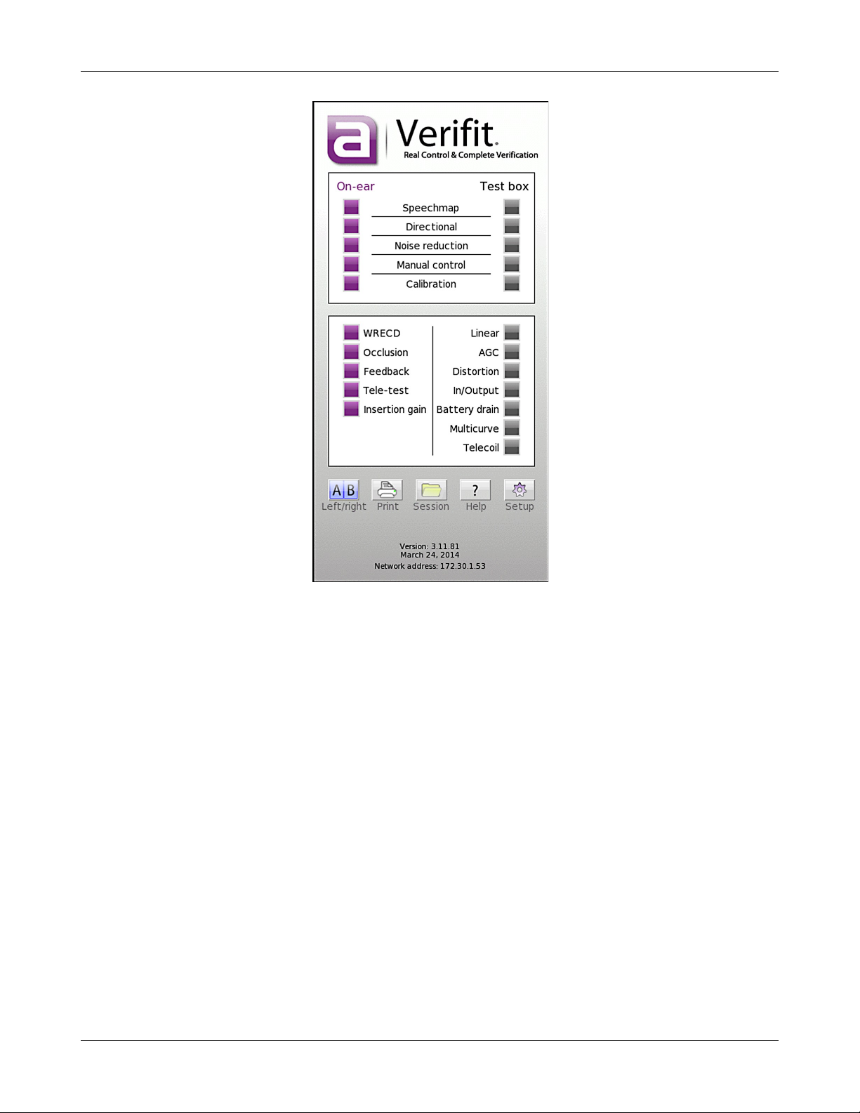
The Verifit is operated with a USB mouse (included) or a keyboard (not included) to select icons and menu
items, operate on-screen buttons and to enter audiometric data. Upon starting the Verifit presents the home menu
for accessing all tests and major functions. To see the home menu at any time, right click the mouse.
To activate an on-screen icon or button, or to select an item from a menu, use the mouse to place the screen
pointer over the icon, button or menu item and left click. To enter a data point on a chart, such as an audiogram,
place the screen pointer over the desired point on the chart and left click. To move the data point, place the
screen pointer near the new location and left click. To delete a data point, place the screen pointer on the data
point and left click. To summon a cursor on a graph, place the screen pointer on the graph and left click, then
navigate to the point you want to identify; left click again to hide the cursor. The scroll wheel may be used to
traverse the Help contents, multiple Help pages or long menu lists. Note that mouse speed can be changed by
clicking and [Display].
28
Verifit®User's Guide Version 4.2 © June 2015
The functions of the screen icons and connected keyboard keys are explained in the following table:
29
Verifit®User's Guide Version 4.2 © June 2015
functions (mouse right click)
switch between A/B test box data
button or menu item
Activate a screen icon or button, or select an
item from a menu (mouse left click)
keypad
entry field.
keypad
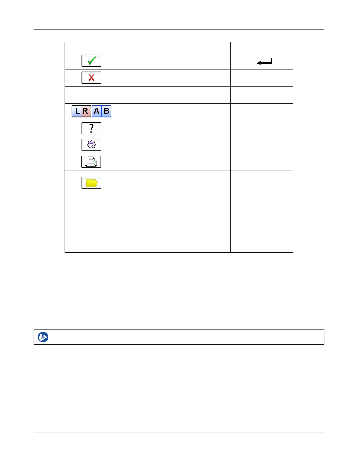
Screen icon Function Keyboard
Continue. Proceed from current state
Cancel. Revert to previous state [Esc]
Show menu of all available tests and
Switch between Left/Right on-ear data or
Show on-line help [F1]
Show the setup menu [F2]
Print screen to an external printer or a file [Print Screen]
Show menu for erasing data or exchanging
data with network files or USB memory
Position the screen pointer over the icon,
Accept text or numbers typed into any text
[F3]
[F5]
[F4]
[Arrow keys]
[Enter] on numeric
[Enter] on numeric
Network connection
The Verifit includes two options for connecting to a computer network, either through the built-in wireless
networking feature, or through an external wired connection. The built-in wireless networking feature requires
no additional attachments to the Verifit. The external wired connection requires inserting a standard network
cable into the network connection on the rear of the display unit, as illustrated in the figure below. You can
choose between either the wireless or wired network connection through the software user interface, as
described in the section Networking.
Failure to follow operating instructions could place the user or operator at risk.
30

Verifit®User's Guide Version 4.2 © June 2015
Inserting the cable for a wired network connection
Printer connection
The Verifit can use printers connected locally through USB, or remotely through a computer network.
Connecting a local printer requires inserting the printer's USB cable into any of the five USB connections
available on the side or rear of the display unit, as illustrated in the figure below. You can choose among the
local and network-connected printers through the software user interface, as describe in the section Printing and
Storing Results.
Failure to follow operating instructions could place the user or operator at risk.
Inserting the USB cable for a locally-connected printer
31

Verifit®User's Guide Version 4.2 © June 2015
Menus, lists and buttons
Buttons containing descriptive text perform an action like opening a prompt. A screen button with a down
arrow indicates that it will summon a drop-down list of options, the current selection being shown in the window
to its left. A plain button toggles between two choices; the current choice is shown in the window to its left. A
sunken text field with a gray background show the state of something that can be changed elsewhere.
Positioning the mouse cursor over a menu button changes it from gray to white; positioning it over a window
with a screen button changes the button from dark gray to light gray. Left clicking the mouse operates the
selected button. A menu button or the window containing a screen button, selected using the arrow keys on a
connected keyboard is surrounded by a heavy line and is operated by pressing the Enter key on the numeric
keypad on the connected keyboard. This process also selects the highlighted item in a drop-down option list.
Screen messages and Help
The Title bar (top line of the display screen) informs you of the selected Test (e.g., Speechmap).
The Message bar (bottom line of the display screen) suggests the next step in a test or informs you of the state of
the instrument or conditions that could affect your data. For example, it will inform you if the microphones need
to be calibrated.
Context-sensitive help is available by clicking on on the Home prompt or pressing F1 on a connected
keyboard. The Help index (left panel) or Help page (right panel) may be selected by left clicking the mouse on
either panel or by pressing the F5 key on a connected keyboard. The side scroll bars on each panel may be used
to scroll through the Help index or long Help pages. This may also be accomplished using scroll wheel on the
mouse or the arrows on a connected keyboard.
Software updating
The Verifit software is available on the Audioscan website, www.audioscan.com. After it is downloaded to your
computer, it can be installed to your Verifit using a USB memory stick.
To update the Verifit:
1.Using your computer, open a browser like Internet Explorer, Firefox, or Chrome and navigate to
www.audioscan.com .
32

Verifit®User's Guide Version 4.2 © June 2015
2.Click on [Software Updates] and fill in the requested information.
3.Double-click the downloaded software.
4.Save the audioscan folder to an appropriate location on your computer, like the desktop.
5.Connect the provided Audioscan update USB stick (or any empty USB stick) to your computer.
6.Double click the audioscan folder, then double click audioscan_update.
7.Click on [Transfer software to USB Stick].
8.When the Software is successfully transferred to the USB Stick, remove the USB stick from your computer
and connect it to any USB port on the Verifit.
9.Turn on the Verifit and follow on-screen directions.
33

Verifit®User's Guide Version 4.2 © June 2015
4 General Setup
This section covers Date and Time setup, Display settings (including mouse pointer speed setting) and Saving
test setup.
Date and time setup
To set the date and time that appears on printouts and calibration screens:
1. Press , then highlight and select [Date & Time] on the Setup poster.
2. To change the date, click on the month window to display a drop-down list of months.
3. Select the desired month on the list.
4. Repeat the previous step to change the date, year and time in the appropriate windows.
5. When the new date and time information has been set, press to exit.
Display settings
To change the screen saver timing or mouse pointer speed:
1. Press , then select [Display].
2. To change the idle time before the screen saver blanks the screen to prolong display life, click the Screen
saver window.
3. Select the desired screen saver timing from the drop-down list.
4. In this screen you can also select the Mouse pointer speed button and select the response speed from the
drop-down list.
5. Press to exit setup.
Saving test setup
This feature lets you retain the last-used stimulus type and level for most tests when the power is turned off and
the last-used target method and transducer type in Speechmap and Insertion Gain tests. This feature also lets
you determine how assessment parameters, test levels and stimuli are treated when , [Erase data] is
selected.
To enable/disable saving of test levels, stimuli and assessment parameters:
1. Press , then click on [Save option]
2. Click [Save test setups on power off] to toggle between Yes and No.
To enable/disable erasing of test levels, stimuli and assessment parameters when Erase data is selected:
1. Press , then click on [Save option]
34

Verifit®User's Guide Version 4.2 © June 2015
2. Click [Save test setups on erase data to toggle between Yes and No.
35

Verifit®User's Guide Version 4.2 © June 2015
5 On-Ear Measures - Setup
For accurate, repeatable measurements, the Verifit must be properly set up and calibrated, the client must be
properly positioned and the probe tube must be properly positioned in the ear canal. Some common terms:
Real-Ear Unaided Response (REUR): SPL, or band SPL, in the open (unaided) ear canal for a given stimulus.
Real-Ear Unaided Gain (REUG): Difference, in dB, between the REUR and the stimulus SPL, or stimulus band
SPL.
Real-Ear Aided Response (REAR): SPL, or band SPL, in the ear canal for a given stimulus, with a working
hearing aid in place.
Real-Ear Aided Gain (REAG): Difference, in dB, between the REAR and the stimulus SPL, or stimulus band
SPL.
Real-Ear Saturation Response (RESR): The REAR obtained using a narrow-band signal at a level high enough to
saturate the hearing aid (usually 85 - 90 dB SPL).
Real-Ear-to-Coupler Difference (RECD): Difference, in dB, between the SPL produced in the ear canal and the
SPL produced in a coupler by the same sound source.
Audioscan Wideband Coupler (AWC): A cylindrical coupler having a volume of 0.4 cc.
Thin-tube and Receiver In Canal (TRIC) adapter: Silicone attachment to the AWC which accepts the nozzle of a
thin-tube or RIC type hearing aid. It will also accept the nozzle of the RECD transducer, an ER-3A insert
earphone and #13 standard earmold tubing.
Wideband Real-Ear-to-Coupler Difference (WRECD): The difference in SPL produced in an occluded ear canal
and in the 0.4cc coupler by a high impedance coupled sound source.
External sound-field speaker setup
In some installations, the internal sound-field speakers may not be convenient or may yield speaker overdriven
errors because of severe standing waves from nearby walls or shelves. In these cases, an external speaker having
a smooth response from 200 - 16000 Hz and an impedance of 4 ohms or greater may be connected to the Front
on-ear measure speaker connector on the rear connector panel. The VA-111 speaker is available for this purpose.
The speaker should be mounted at ear height, well away from reflective surfaces. See Positioning the client.
To select this speaker:
1. Right-click to raise the home menu, then left-click [Speakers].
2. Toggle the Sound-field speaker button between [Internal] and [External].
3. Click to exit Setup
For on-ear directional tests, connect an external speaker (see requirements above) to the back on-ear speaker
connector on the rear connector panel. Position the back speaker directly behind and facing the back of the
client’s head so that front and rear speakers are at the same height and are at the same distance from the center
36

Verifit®User's Guide Version 4.2 © June 2015
of the client’s head. This speaker will be automatically used for the on-ear directional test.
On-ear calibration facts
The probe microphone and its associated tubing does not have a flat frequency response. The on-ear calibration
process compares this response with the flat, factory-calibrated response of the on-ear reference microphone and
compensates all subsequent probe-tube measurements for this difference. It may be performed as often as
desired but will be invalidated at 12 am the following day or at 12 am the following Monday, depending on the
choice of daily or weekly calibration interval. After the calibration has expired, you will be prompted to
calibrate whenever you attempt a test that uses the on-ear measurement microphones.
It is suggested that a copy of the calibration curves for the probe modules when new be posted near the Verifit
for comparison with daily or weekly curves. If there is a drift in calibration with time, the module may need
replacement. See Calibration check for probe module.
Calibration should be repeated if a probe module is replaced or if a probe-tube with different dimensions is
installed.
Switching left and right probe modules after calibration will result in the wrong calibration curve being applied.
Calibration of on-ear probe microphone
For convenience, the probe microphones can be calibrated while seated in the probe dock. Ensure the connectors
of both probe microphone assemblies are plugged into the appropriate jack on the bottom of the probe dock. See
Microphone connection and On-ear calibration facts
1. Right-click to raise the home menu and click on [Calibration] under [On-ear measures].
2. Press the enlarged end of a probe tube as far as it will go, into the recessed opening at the top of the probe
module.
3. Position the open end of the probe tube in front of the reference microphone inlet and press it between the
posts as shown.
4. Hold the probe dock 15 - 90 cm (6 – 36 in.) away from and directly in front of the sound-field loudspeaker
with the microphone to be calibrated facing the speaker.
5. Left-click calibrate. The resulting curve should be similar in shape to that shown but may be shifted +/- 5 dB.
6. To change the calibration interval, toggle [Daily] or [Weekly].
Click on calibrate for the other ear and repeat the process for the other probe module.
37
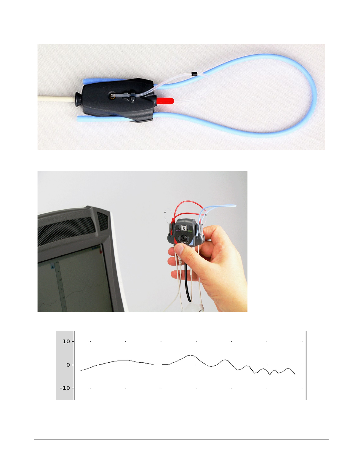
Verifit®User's Guide Version 4.2 © June 2015
Position the probe tip over the reference microphone
Hold probe dock with microphone to be calibrated facing speaker.
Typical calibration curve. Level may be shifted +/- 5dB.
38
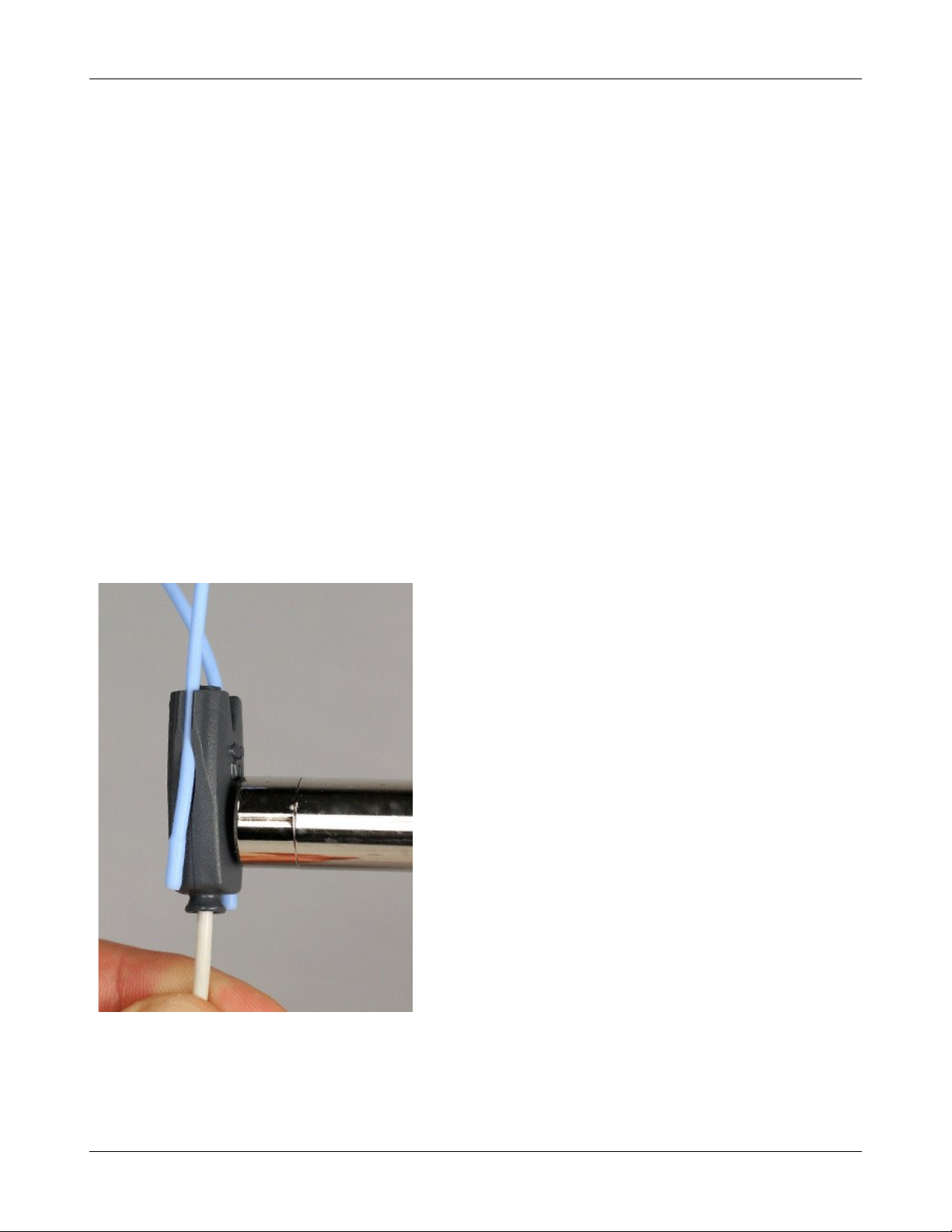
Verifit®User's Guide Version 4.2 © June 2015
Calibration check for probe module
The calibration curve for the probe module is a comparison of the response of the probe microphone (with tube)
to the response of the on-ear reference microphone. Any change in the curve indicates a change in one of these
microphones (or the probe tube). See Calibration of on-ear probe microphone. As part of a regular calibration
schedule, or to investigate changing calibration curves, the on-ear reference microphone may be checked against
a high quality sound level meter.
1. Right-click to raise the home menu and click [Manual control] under On-ear.
2. Click [Level], then select 70 from the drop-down list.
3. Click [Frequency], then select 2000 Hz from the drop-down list.
4. Click [Start test] (which changes to [Stop test]).
5. Hold the probe module about 45cm (18 in.) in front of the sound-field speaker.
6. Hold the microphone of a calibrated sound level meter next to the on-ear reference microphone as shown.
Set the sound level meter to C weighting and slow.
7. The sound level meter should read 70 ±2 dB.
8. Repeat with the frequency at 250 Hz.
9. To stop the measurement, left-click [Stop test].
The probe module should be replaced if it fails this test.
39

Max TM SPL setup
The Max TM SPL safety feature allows you to set a limit on the SPL, measured by the probe microphone, above
which a test terminates. The MAX TM SPL limit is shown on all on-ear measurement screens. The default limit
is 120 dB.
To choose a different Max TM SPL setting:
1. Right-click the mouse to raise the home menu, then left-click , then left-click [Max TM SPL].
2. Click on the current Max TM SPL setting and select the desired Max TM SPL setting from the drop-down
list.
3. Click to exit Setup.
This Max TM SPL setting will be in effect until you change it.
If the limit is exceeded during an on-ear test, the Verifit will terminate the test and display the message 'Max
TM SPL Exceeded'. You must then decide to either reduce the maximum output limit of the hearing instrument
or increase the Max TM SPL setting following the steps above.
If the Max TM SPL limit has been disabled, a notice will appear on each real-ear screen. Also, a message
reminding you that the Max TM SPL limit has been disabled will appear when you select an on-ear test.
Verifit®User's Guide Version 4.2 © June 2015
ABR nHL to eHL setup
Estimated Hearing Level (eHL): An estimate of the behavioral pure tone threshold that accounts for a
measured ABR threshold.
Normalized Hearing Level (nHL): (a) Stimulus peak-to-peak equivalent SPL (pe SPL) at ABR threshold
relative to the average stimulus pe SPL at ABR threshold of a normal-hearing jury OR (b) stimulus SPL at ABR
threshold relative to the average stimulus SPL at behavioral threshold of a normal-hearing jury for the same
stimulus. (Note that in this latter case, nHL is equivalent to eHL).
In Speechmap/DSL you have the option of entering ABR thresholds in either eHL or nHL. If eHL is selected,
the threshold is treated as if it were a behavioral pure-tone threshold. If nHL is selected, the entered data will
first be converted to eHL before SPL threshold and fitting targets are calculated. To do this, appropriate eHL to
nHL conversion factors must be applied. You can choose to apply default conversion factors or enter new ones
for each client.
This setup allows you to select the default conversion factors that are applied in Speechmap/DSL to convert
ABR nHL threshold to eHL threshold.
1. Right-click the mouse to raise the home menu, then left-click , then left-click [ABR eHL to nHL].
2. Left-click [DSL defined] or [User defined]
3. For [User defined], enter conversion factors using a mouse or a keyboard. See Assessment data entry.
Positioning the client
Sound reflections from nearby surfaces (including the operator) can cause large measurement errors, especially
if the client moves between REUR and REAR measurements. Room noise can increase test time, cause errors
and alter the operation of the hearing instrument being evaluated.
40

Verifit®User's Guide Version 4.2 © June 2015
1. Choose a quiet location and position the client and the sound-field speaker at least 1.5 m (5 feet) away from
any hard surfaces.
2. Position the client directly in front of, and facing, the sound-field speaker at a distance of 45 to 90 cm (18 to
36 in.) from the center of the head.
3. Position the back speaker (if used) directly behind and facing the back of the client’s head so that front and
rear speakers are at the same height and are at the same distance from the center of the client’s head.
Positioning the probe tube
1. Use an otoscope to ensure there is no ear canal obstruction (e.g. cerumen) and to get a sense of ear canal
length.
2. Install a new probe tube on the probe module. Set the black marker ring approximately 28 mm from end of
probe tube for adult females, approximately 30 mm from end of probe tube for adult males and
approximately 20-25 mm from end of probe tube for children. These positions may be modified based on the
otoscopic examination.
3. Clip the probe dock to the client's clothing, near the middle or to one side. If more convenient, it can
alternatively be clipped to the chair back or to a lanyard. It needs to be positioned so that the probe
microphone(s) will easily reach the subject's ear(s).
4. Hang the probe microphone on the ear, as shown below. The reference microphone should face outwards.
5. Adjust the blue or red lanyard until the probe microphone module is snug against the head, directly below the
earlobe (cheek level). Use the probe cables adjust clip to take up slack in the cables where necessary to
ensure correct positioning.
6. Pull the front lanyard so that it passes behind the ear canal entrance and pass the end of the probe tube in
front of the lanyard and into the ear canal.
7. Carefully slide the probe tube into the ear canal until the marker ring approaches the intertragal notch. Then
let the front lanyard move forward to hold the probe tube in place. Use an otoscope to verify that the tube is
2 to 5 mm from the eardrum.
41
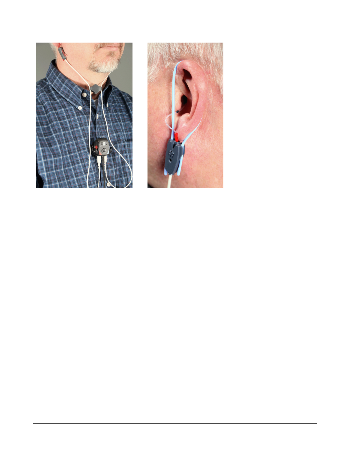
Verifit®User's Guide Version 4.2 © June 2015
Probe dock positioned, clipped to client clothing, adjust clip holding probe microphone modules in place.
Probe tube insertion: the colored lanyard holds the tube in place and the depth marker is at the intertragal notch
42

Verifit®User's Guide Version 4.2 © June 2015
6 On-Ear Measures Screen Setup
To accommodate your working preferences, the appearance of On-ear measurement screens may be changed in
several ways.
On-ear single or dual view
Most on-ear screens give you the option of selecting either a single, full-screen view or a dual, side by side
view. Some data may be dropped from the dual view.
To change the presentation, left click [Single view] or [Dual view].
To switch between left and right test panel in single view, right-click the mouse to raise the home menu and
click the L|R button.
To switch between left and right test panel in dual view, left-click the mouse on a screen button in the inactive
test panel or right-click the mouse to raise the home prompt and click the L|R button.
Graph, table or 2cc target format
Most on-ear test screens may be viewed in graphic or tabular format.
• In Speechmap, WRECD and Directional tests, left-click [Format] to toggle between [Graph] and [Table]
views.
• In Insertion gain, left-click [Format], then select [Graph], [Table] or [2cc targets] from the drop-down list.
• In [2cc targets] format, reserve gain and fitting formula may be changed. Choose and change reserve gain
or fitting formula from the drop-down list with a mouse left-click.
SPL or HL scale
In Insertion gain tests you may view results in either dB HL or dB SPL.
Insertion gain tests view the hearing aid as improving the sound-field threshold. In Insertion gain, the HL scale
presents aided results as improved sound-field thresholds while the speech region remains fixed.
Speechmap tests view the hearing aid as increasing the ear canal SPL. Speech gets louder but the threshold
remains fixed. All instructions given in this guide assume the SPL Speechmap scale.
To change the scale:
Left-click [Scale] to toggle between a dB SPL and dB HL scale.
Hide or show on-ear curves
To hide or show unaided and aided curves on the Speechmap screen:
1. Click on the Hide/Show buttons located beside the Play button and Test identifier numbers. Note that the
Hide/Show aided button has 3 states – Curves hidden, display LTASS only and display LTASS + speech
envelope (i.e. the 'speech banana').
43

Verifit®User's Guide Version 4.2 © June 2015
Hiding a curve does not erase it. To erase curves click on and select one of the Erase options.
To hide or show test curve(s) in all other applications:
1. Left-click [Hide/Show].
2. Click on the desired test result to toggle between the Hide or Show options. The curves will toggle on or off
when selected.
3. Click within the Curve Display poster to return to the test screen.
Hiding a curve does not erase it. To erase curves click on and select one of the Erase options.
44

7 Speechmap
Speechmap presents hearing threshold, UCL and amplified speech spectra as SPL in the ear canal. The fitting
goal is to make amplified speech audible and comfortable while avoiding discomfort for loud sounds.
Speechmap may be accessed by right clicking and selecting Speechmap under Test box or On-ear. See On-ear or
Test box mode for details.
Speechmap is only used in SPL and this guide describes only this usage.
Speechmap facts
Speechmap is a trademarked hearing instrument fitting environment introduced by Audioscan in 1992. It
presents hearing threshold, UCL and amplified speech spectra as SPL in the ear canal. The fitting goal is to
make amplified speech audible and comfortable while avoiding discomfort for loud sounds. Originally speech
was simulated using amplitude-modulated tonal signals. The Verifit replaces these simulated speech signals with
real speech, both recorded and live. For details of the test signals and analysis methods, see Speechmap
Technical Details.
Speechmap departs from insertion gain target methods in presenting amplification goals in the context of the
residual auditory area, not as an isolated target line, and in the use of real speech, not tones or broad-band noise.
This is extremely important for non-linear hearing aids, analog or digital, because their processing is signaldependent. It also makes provision to correct audiometric data and coupler measurements for age-related or
individually-measured acoustic differences between real ears and the couplers used for calibration and testing.
Verifit®User's Guide Version 4.2 © June 2015
DSL 5.0 in Speechmap
Copyright DSL ® 2004. Version 5.0
The Desired Sensation Level (DSL) method is a systematic eardrum sound pressure level (SPLogram) approach
to hearing instrument fitting that seeks to ensure amplified speech will be audible and comfortable while loud
sounds will not be uncomfortable. It takes into account individual acoustic factors in audiometric and
electroacoustic data. DSL was developed by the National Centre for Audiology (NCA), London, Ontario.
Audioscan has implemented DSL within its Speechmap fitting system since 1994.
In 2005, DSL underwent an extensive revision resulting in DSL 5.0. It was further revised in 2007 to version
5.0a. See DSL 5.0 changes for details of the changes.
The Audioscan version of DSL 5.0 may differ from others in the following ways:
1. DSL 5.0 uses RECD values for ages > 119 months from a different source than for ages up to and including
119 months; Audioscan has used the RECD values for a 119 month old for ages > 119 months so all values
come from the same study.
2. Input-output curve targets and compression threshold targets are not provided. Such steady-state parameters
are of little value in estimating amplified speech levels. Matching amplified speech to the LTASS targets at
levels from 50 to 75 dB SPL provides much better assurance that fitting goals are being met.
3. There is no provision to input the number of compression channels. This may be useful when the signal used
for verification is not the signal for which the targets were developed. It is irrelevant when using real-speech
signals to match speech targets and when using narrow-band signals to match narrow-band maximum output
targets.
4. The term Uncomfortable Level (UCL) is used rather than Upper Limit of Comfort (ULC) in referring to the
45

Verifit®User's Guide Version 4.2 © June 2015
ear canal SPL that should never be exceeded.
5. Broadband output limiting targets are not provided.
NAL-NL1 in Speechmap
The NAL-NL1 procedure seeks to amplify speech such that all bands of speech are perceived with equal loudness
while maximizing speech intelligibility and ensuring that the wearer perceives speech to be no louder than that
which a normal hearing person would perceive. Although NAL-NL1 states its goals for speech, it derives
insertion gain targets assuming noise as a verification signal. Because it is more accurate to verify a non-linear
fitting using the signal for which the procedure was developed, Audioscan converts the NAL-NL1 insertion gain
targets to LTASS targets for amplified speech in the Speechmap environment, resulting in Speechmap/NAL-
NL1. The conversions use the same adult average RECD and REUG as used in DSL. The RESR targets are from
Hearing Aids (Dillon, Thieme Publishing, 2001, p274).
An insertion gain version is available by selecting [Insertion gain] from the on-ear measures test menu. The pink
noise stimulus should be used.
NAL-NL2 in Speechmap
Fitting targets, default age-related RECD and REUG are provided by a software library used under license from
Hearworks Pty Ltd. which is solely responsible for their derivation.
This revision of NAL-NL1 has many more input parameters and output target formats than its predecessor. In
implementing NAL-NL2, Audioscan has made the following simplifications and clarifications:
1. NAL-NL2 targets are provided as REAR targets in Speechmap. Insertion Gain targets are not provided.
2. There is no provision to select Insert earphones + earmold as the audiometric transducer since this
invalidates the audiometer calibration and correction for this error is problematic.
3. Input-output curve targets and compression threshold targets are not provided. Such steady-state parameters
are of little value in estimating amplified speech levels. Matching amplified speech to the LTASS targets at
levels from 50 to 75 dB SPL provides much better assurance that fitting goals are being met.
4. There is no requirement to input client gender. The impact of gender on REAR targets is less than +/- 1dB.
5. There is no requirement to input hearing aid experience. An "Experienced" user is assumed.
6. There is no provision to generate targets for tonal languages.
7. There is no requirement to input the number of compression channels. This may be useful when the signal
used for verification is not the signal for which the targets were developed. It is irrelevant when using realspeech signals to match speech targets and when using narrow-band signals to match narrow-band maximum
output targets.
8. There is no requirement to input compression speed. It has no impact on REAR targets.
9. There is no requirement to input earmold tubing type. It has no impact on REAR targets.
10.There is no requirement to input vent size or fitting depth. They have no impact on REAR targets.
11.For sound-field threshold the speaker is assumed to be at 45 degrees. For on-ear measurements, the speaker
is assumed to be at 0 degrees and the reference microphone is assumed to be on the head surface.
12.The SII calculation is per ANSI S3.5-1997 and is the same for all fitting fitting methods.
46
Verifit®User's Guide Version 4.2 © June 2015
Camfit in Speechmap
Camfit is an approach to fitting hearing aids developed by Brian Moore at the University of Cambridge, UK. It
specifies the level-dependent gain required to correct abnormal loudness as modeled by his cochlear hearing loss
simulation. It provides two approaches to correcting for the hearing loss:
Camfit restoration aims to amplify sounds that are soft, comfortable and loud for a person with normal hearing
so that they are soft, comfortable and loud for a hearing aid wearer. This is the stated goal of the IHAFF
(International Hearing Aid Fitting Forum) fitting method.
Camfit equalisation aims to amplify speech to produce the same loudness in each critical band. It has been
argued that this is likely to give the highest intelligibility for a given overall loudness. This is the rationale
behind the NAL fitting methods and will generally produce similar targets.
Using Speechmap
The Speechmap fitting environment provides a number of distinctly different stimuli. Speech and noise are
analyzed in 1/3 octave bands and for most speech stimuli data are presented as 3 curves. The top curve is the
level exceeded 1% of the time (speech peaks), the lower curve is the level exceeded 70% of the time (speech
valleys) and the middle curve is the average. Clicking causes the signal to be presented continuously - the
speech signals run in a loop - and the curves are updated frequently to show any changes you make to the
hearing instrument. Clicking on restarts the speech passage and the curves are then calculated for the entire
passage, producing an accurate display of the speech region and LTASS, and an accurate SII calculation. When
using live speech, a pause button [;] captures short-term speech features. See SII calculation in Speechmap and
Speechmap Technical Details.
Before starting, please see On-Ear Measures - Setup, Speechmap Setup, Speechmap facts, On-ear or Test box
mode.
• To access Speechmap: right click and then select Speechmap under On-ear or Test box.
• To change screen setup: see On-Ear Measures Screen Setup, and On-ear or Test box mode.
• To set up hearing instrument type: click on ▼ in the Audiometry section and select BTE, ITE,
ITC, CIC, RITE (receiver in the ear – test box mode), Open (On-ear mode), Body, CROS (On-ear
mode) or FM from the list.
• To enter audiometric data: see Assessment data entry.
• To start a test: click on in any of the test areas
• To select stimulus type: click the down arrow beside the stimulus window and select from the list. See
Setup Speechmap to customize the list.
• To select stimulus level: click the down arrow beside the stimulus window and select from the list.
• To complete a measurement and store the result: click on while the stimulus is running.
• To stop a test without recording any test data: click on
• To capture the current screen curves when using live speech: click on the pause button [;].
See, Screen tour and Speechmap Fitting Procedures.
Speechmap Setup
Speechmap provides a number of different test stimuli for fitting hearing aids and testing various aspects of their
performance. Each time you run a test, you have the opportunity to select the stimulus from a list. You can
manage which stimuli appear on this list by doing the following:
47
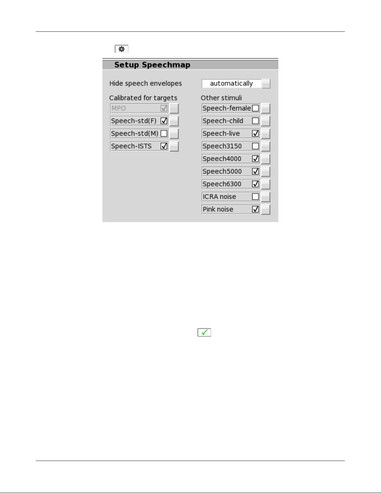
Verifit®User's Guide Version 4.2 © June 2015
Right click and select , then click [Speechmap].
The available Speechmap stimuli are in two columns. The left-hand column contains the MPO stimulus and
speech stimuli that have the specific Long-Term Average Speech Spectrum (LTASS) required when matching
prescription fitting targets such as DSL, NAL-NL1 or NAL-NL2. The MPO stimulus (used to verify that the
maximum output SPL of the hearing aid does not exceed the uncomfortable level) is always selected. You must
select at least one of the defined LTASS speech stimuli.
1. To select a stimulus, click the box beside the stimulus you want to add to the list. A check mark will be
placed next to the selected stimulus.
2. To remove a checked stimulus from the list, click the box beside the stimulus you want to remove.
You can also choose to have the envelopes of the speech test results automatically hidden (leaving only the
LTASS) when you start another test. Click the Hide speech envelopes button to toggle between automatically
and manually.
When you have finished making your selections, click to exit Setup.
48

Verifit®User's Guide Version 4.2 © June 2015
Screen tour - unaided screen
1. Max TM SPL (change this in Setup), 2. Estimated UCL, 3. Unaided long-term average speech spectrum
(LTASS), 4. Impaired threshold, 5. Normal threshold (MAP), 6. Turn on/off display of unaided speech region, 7.
Unamplified speech region, 8. LTASS +12dB, 9. LTASS -18dB
49
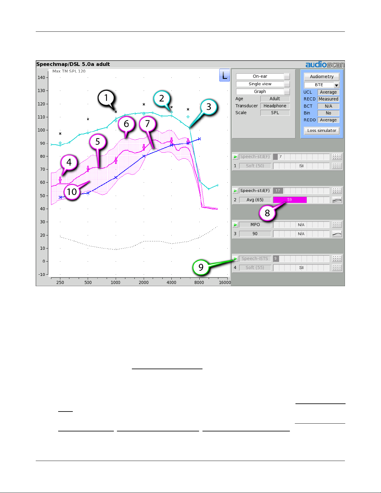
Verifit®User's Guide Version 4.2 © June 2015
Screen tour - aided screen
1. Estimated UCL, 2. 90dB target (for tones), 3. Result of test 3 (MPO), 4. LTASS targets for Test 2, 5. Long
term average speech spectrum (LTASS) result of test 2, 6. Speech peaks (99th percentile), 7. Speech valleys (30
percentile), 8. Speech intelligibility index (SII), 9. Start test, 10. Amplified speech region
On-ear or Test box mode
The Speechmap environment provides two hearing instrument verification options: On-ear measures and Test
box measures. Using on-ear mode, the stimulus is controlled by the on-ear reference microphone below the ear
and SPL in the ear canal is measured by the probe microphone. In test box mode, levels measured in the coupler
are converted to estimated ear canal levels using the RECD or WRECD values (age-appropriate average,
entered, or measured) See Speechmap screen choices . In addition, the stimulus delivered to the hearing
instrument microphone is modified to include average microphone location effects for the hearing instrument
type indicated. The screen display for both modes is the same, showing SPL, measured or simulated, in the ear
canal.
For On-ear mode: right click and click on Speechmap from the On-ear column. Review On-Ear Measures Setup,
For Test box mode: right click and click on Speechmap from the Test box column. Review Calibrating test box
reference microphone, Coupling the hearing instrument, Positioning the hearing instrument.
To switch modes: click on [Mode] to toggle between On-ear and Test box modes.
th
50

Verifit®User's Guide Version 4.2 © June 2015
It is suggested that hearing instruments be preset in Test box mode with fine tuning done in On-ear mode.
Note that On-ear mode should be used for vented or open fittings. Vent effects depend on the vent, the ear and
the hearing aid settings and cannot be reliably predicted from coupler measurements.
SII calculation in Speechmap
The Verifit calculates a Speech Intelligibility Index (SII) value (in %) for unaided speech at 65 dB SPL and for
each aided test. The calculations use the 1/3 octave band method of ANSI S3.5 –1997 without the 160 Hz band
and without masking effects with results expressed as a % by multiplying by 100. Level distortion effects are
included but no hearing loss desensitization is applied. An idealized speech region of LTASS +/- 15 dB is used.
The speech recognition associated with a given SII is a function of the test material and the cognitive abilities of
the listener. There is considerable individual variability in relating the SII to speech recognition, especially
amongst impaired listeners. The following shows expected nominal recognition scores vs SII for normals when
using a variety of speech stimulus conditions. (Killion and Mueller, Hearing Journal, January, 2010 pp 10-15).
Using custom stimuli in Speechmap
Custom digital sound files can be used as stimuli in Speechmap. If you connect a USB stick with WAV files on
it to the Verifit, Speechmap will make those files available as stimulus selections. This feature provides the
freedom of using any stimulus in Speechmap with all the features that Speechmap offers. Please note that fitting
targets are not available for custom stimuli.
A USB stick is required for this feature. It is highly recommended that the USB stick is formatted for data using
the Audioscan Updater prior to using this feature. The Audioscan Updater comes with any current Audioscan
software download or CD. Visit www.audioscan.com to obtain software updates.
To use digital sound files as stimuli in Speechmap:
1. Connect a USB stick to your PC.
51

Verifit®User's Guide Version 4.2 © June 2015
2. Format the USB stick for data using the Audioscan Updater.
3. Create digital sound files that are compatible with Speechmap (see Creating WAV files for Speechmap).
4. Copy the WAV files from the PC to the top level directory (i.e. not in any folder) of the USB stick.
5. Disconnect the USB stick from the PC and connect it to the USB port on the Verifit.
6. Start a Test in Speechmap (see Using Speechmap).
7. Click [Stimulus]. Compatible WAV files will appear as selectable options in the stimulus list below the
default stimuli. You may need to scroll down to see all the stimuli.
8. Choose your custom stimulus. After a short delay, your stimulus will begin playing.
9. Use your new stimulus with all the features of Speechmap.
Example of two custom files, click.wav and 1khztone.wav, in the stimulus list.
To remove custom stimuli from Speechmap: close any Test prompts and disconnect the USB stick from the
Verifit.
Notes:
1. Files that are greater than 20 seconds in duration will be truncated to 20 seconds.
2. Speechmap will show up to 10 compatible WAV files. If you have more than 10, we recommend that you use
52

Verifit®User's Guide Version 4.2 © June 2015
multiple USB sticks or organize your files into folders, moving them into the top level directory of the USB
stick as needed.
3. Removing the USB stick while a Test poster is open may cause unexpected behavior. Close the Test poster
before removing the USB stick from the Verifit.
Creating WAV files for Speechmap
WAV is a commonly used format for digital audio and can be created/edited by nearly all audio editing and
recording software. A WAV file has many properties that define the format of the digital audio. When a USB
stick is connected to the Verifit, Speechmap looks for files in the top level directory that have the following
properties:
File format: WAV
Data format: PCM (no compression)
Sampling Rate: 32 kHz
Bit precision: 16 or 32 bit
Channels: Mono
File name: 15 characters or less, not including .wav extension
Existing WAV files can easily be converted to match these specifications using your preferred audio editing
software.
Leveling Options
By default, Speechmap will automatically level the WAV file so that the SPL matches the level selected for the
test.
The automatic leveling of the WAV file can be modified by inserting a tag in the filename. This feature allows
you to fine tune the output level of your stimulus. The tag must be added at the end of the filename but before
the extension.
Example: filename_+2.5.wav
The tag must consist of an underscore, followed by a plus or minus sign, followed by the modifier in dB. In the
example above, the tag "_+2.5" will level the file to be 2.5 dB above nominal.
There are no restrictions on the magnitude of the modifier; there is built-in protection against speaker overdrive.
Precision is limited only by the 15 character limit of the filename.
53

Verifit®User's Guide Version 4.2 © June 2015
Example of user-supplied files, user.wav, user_-4.wav and user_+2.5.wav.
54

Verifit®User's Guide Version 4.2 © June 2015
8 Speechmap Fitting Procedures
The Speechmap fitting screen provides a number of choices for inputting and applying audiometric data for the
verification of hearing instrument fittings. The procedures in this section assume a familiarity with Test Box
Measures - Setup, On-Ear Measures - Setup, On-Ear Measures Screen Setup and Speechmap.
Speechmap screen choices
Speechmap screen choices are made by clicking on the relevant buttons for [On ear or Test box], [Graph or
Table], [Dual view or Single view], [L or R or L+R], [Audiometry], [BTE + HA-4, BTE + mold, ITE, ITC, CIC,
RITE, Body, Open, CROS or FM] and [Loss simulator] Clicking on [Audiometry] will cause a related selection
poster to be presented. Changes made on this poster are applied and the poster closed by clicking on . The
poster may be closed without applying the changes by clicking .
Defaults are the last-used choices if test setup memory has been turned on. See Saving test setup.
1. Targets: Fitting rule. Select from DSL Adult, DSL Child, NAL-NL1, NAL-NL2, Camfit restoration,
Camfit equalisation or None.
2. HL Transducer: Sound source used to obtain the audiogram. Select from [Headphone, Insert + foam, Insert
+ mold (DSL only) or Soundfield. If Headphone is selected, average adult real-ear to dial difference (REDD)
is used to convert entered HL values to ear canal SPL. If Insert + foam is selected the appropriate real-ear to
coupler difference (RECD) is used to convert entered HL values to ear canal SPL values. If Insert + mold is
selected, the audiometer is no longer calibrated and a measurement protocol is provided for accurate
conversion of entered HL values to ear canal SPL. If Measure is not selected, entered HL values are
converted to ear canal SPL as if a foam tip had been used to obtain the audiogram. If Soundfield is selected
appropriate real-ear unaided gain (REUG) values @ 45 degrees azimuth, will be used to convert HL values
to ear canal SPL values.
3. Bone conduction: Select from [N/A or Enter]. If [Enter] is selected, an entry screen will be provided after
the air conduction thresholds have been entered.
4. UCL: Uncomfortable Level. Select from [Enter or Average]. If Average is selected, UCL will be estimated
from entered thresholds. If [Enter] is selected, an entry screen will be provided after the air (and bone)
conduction thresholds have been entered. If measured UCL values are entered, these values will be converted
to real-ear SPL and used as real-ear saturation response (RESR) targets. Note that DSL 5.0 has changed this
term to Upper Limit of Comfort (ULC). Regardless of the acronym, it is a narrow-band SPL that should
never be exceeded.
55

Verifit®User's Guide Version 4.2 © June 2015
5. RECD: Real-ear to coupler difference. Unless otherwise indicated, RECD is the difference between the SPL
in an occluded ear and the SPL in the HA-1 2cc coupler produced by the same high (acoustic) impedance
sound source with the same acoustic coupling. Because of standing waves in the 2cc coupler, it is not useful
above 8 kHz. The Verifit has adopted a 0.4cc coupler to extend the capabilities of Speechmap Test box to
the 1/3 octave band at 12.5 kHz. The term Wideband real-ear to coupler difference (WRECD) has been
coined to denote an RECD based on a 0.4cc coupler rather than the HA-1 coupler. The WRECD is the
difference between the SPL in an occluded ear and the SPL in the 0.4cc coupler produced by the same high
(acoustic) impedance sound source with the same acoustic coupling.
The WRECD is used to convert 0.4cc coupler SPL measured in the test box to estimated ear canal SPL. The
WRECD is used to convert entered HL data (thresholds and UCL's) to ear canal SPL when Insert +Foam is
selected as Transducer. Below 8 kHz, the Verifit converts between RECD and WRECD as necessary.
Except for Camfit targets, RECD choices are Average, Enter, or Measure.
If Average is selected and DSL child or NAL-NL2 is the target rule, age-appropriate average RECDs will be
applied. However, these target rules provide different average values which will result in differing SPL
thresholds. Average RECDs for frequencies above 6 kHz are set equal to the 6 kHz value for purposes of
converting HL thresholds and 0.4cc coupler SPL to ear canal SPL.
If Enter is selected, after threshold entry has been completed, a selection must be made between HA-2
RECD, HA-1 RECD and 0.4cc WRECD. Once a choice has been made, an 8 kHz RECD entry screen or a
12.5 kHz WRECD entry screen becomes available.
If Measure is selected, the Measure WRECD screen is provided after threshold entry is completed. See
WRECD measurement.
6. RECD Coupling: Select from [Earmold, Foam tip]. Specifies the coupling between the RECD transducer
and ear.
7. Age: Select from Adult, 6 – 10 years, 1 – 60 months. This changes the RECD applied if DSL Average or
NL2 Average has been selected when using these target rules.
8. ABR nHL to eHL: Normalized HL to estimated HL conversion factors. Permitted only if [Transducer] =
ABR (nHL). Select from [Default, Enter]. If [Enter] is selected, an entry screen will be provided after
threshold data have been entered. Otherwise default factors will be used. These may be set to DSL values or
to values that you have entered in Setup. Note that, in some facilities, nHL is defined in such a way that it is
effectively eHL; in these cases, ABR (eHL) should be selected and no conversion factors will be applied. See
ABR nHL to eHL setup.
9. Binaural: Select from [Yes, No]. Determines if fitting targets will be adjusted for binaural summation
effects.
10.REDD: Real-ear-to-Dial Difference. [Average] (this cannot be changed). REDD values are similar for adults
and children. If Headphone is selected as the transducer type, adult average values will be used to transform
dB HL audiometry to dB SPL.
Type of instrument or fitting to be verified: In Test box mode, select from BTE, ITE, ITC, CIC, RITE
(receiver in the ear), Body or FM. In On-ear mode, select from BTE, ITE, ITC, CIC, Open, Body, CROS or FM.
In Test box mode, the fitting selection determines the microphone location effects applied to the stimulus and, in
the case of Open, CROS and FM, the test protocol used. In the case of a CIC a deep insertion factor is applied to
the estimated ear canal SPL. See Speechmap Technical Details.
Loss simulator: An electro-acoustic simulation intended to allow normal-hearing listeners to hear sounds as if
they had the elevated threshold and altered loudness perception caused by outer and inner hair cell damage. See
Sensory loss simulator.
56

Verifit®User's Guide Version 4.2 © June 2015
Data entry
Threshold data and other audiometric parameters may be entered manually using a mouse or an external
keyboard. See Mouse, keyboard, and Input device operation.
To enter audiometric data manually:
1. On the Threshold, UCL or RECD entry screens, enter each data point using a mouse or an external keyboard.
Left click the mouse to enter a point. Click again to delete the point. On the keyboard, the arrow keys change
frequency and level and the ENTER key on the numeric keypad enters or deletes a point. The keyboard's
numeric keypad can also be used to type in data.
2. Click to save the data and exit the entry screen. Click to exit the entry screen without saving the
data.
Fitting to targets for soft speech
See Speechmap screen choices for setup and audiometric data entry. See Using Speechmap.
1. Follow the instructions in Speechmap screen choices to enter audiometric data and select the fitting rule.
2. Click in the "1" area to start the first test . Once the test is started, click the [Stimulus] list button to
select the stimulus type. Click the [Level] list button and select a stimulus level of 50 dB.
3. While the passage is being presented, adjust the hearing instrument's frequency shaping and gain for soft
sounds so that the middle curve (the LTASS) falls within the target range, shown by the symbols,
especially between 500 - 4000 Hz. These target symbols are automatically adjusted for the stimulus level you
select.
4. Click to signal average and store a complete passage. Repeat as necessary.
5. Click to stop the test without recording any test data.
6. Upon completion of a test recording, a colored Aided Audibar shows the SII for the aided soft speech signal.
7. The upper bar in the "1" area, shows the SII for the unaided stimulus at 50 dB SPL (the Unaided Audibar).
The difference between the unaided and aided SII score (and the associated length of their respective
'Audibars' ) visually quantifies the speech intelligibility improvement for soft speech likely provided by the
hearing instrument being fit. To further demonstrate the improvement, the unaided speech 'banana' may be
displayed by clicking beside the Unaided Audibar.
57

Verifit®User's Guide Version 4.2 © June 2015
After completion of a test, the chosen stimulus type and level will become the default. To change this behavior,
see Saving test setup.
Fitting to targets for average speech
See Speechmap screen choices for setup and audiometric data entry. See Using Speechmap.
1. Follow the instructions in Speechmap screen choices to enter audiometric data and select the fitting rule.
2. Click in the "2" area to start the second test. Once the test is started, click the [Stimulus] list button to
select the stimulus type. Click the [Level] list button and select a stimulus level of 65 dB. The upper bar in
this area shows the SII for the unaided stimulus at 65 dB SPL (the Unaided Audibar). When you start a new
test, the speech envelope of the previous test may be automatically hidden. See Speechmap Setup to change
this behavior. To change the default stimulus type and level see Saving test setup.
3. While the passage is being presented, adjust the hearing instrument's frequency shaping and gain for average
sounds so that the middle curve (the LTASS) falls within the target range, shown by the symbols,
especially between 500 - 4000 Hz. These target symbols are automatically adjusted for the stimulus level you
select.
4. Click to signal average and store a complete passage. Repeat as necessary.
5. Click to stop the test without recording any test data.
58

Verifit®User's Guide Version 4.2 © June 2015
Upon completion of a test recording, a colored Aided Audibar shows the SII for the aided average speech signal.
The difference between the unaided and aided SII score (and the associated length of their respective 'Audibars')
visually quantifies the speech intelligibility improvement for soft speech likely provided by the hearing
instrument being fit. To further demonstrate the improvement, the unaided speech 'banana' may be displayed by
clicking beside the Unaided Audibar.
Adjusting the Maximum Output Level
See Speechmap screen choices for setup and audiometric data entry. See Using Speechmap.
Follow the instructions in Speechmap screen choices to enter audiometric data and select the fitting rule.
1. Click in the 3 area to start the third test. Once the test is started, click the [Stimulus] list button to select
the stimulus type as MPO. When you start a new test, the speech envelope of the previous test may be
automatically hidden. See Speechmap Setup to change this behaviour. To change the default stimulus type
and level see Saving test setup.
2. In Test box mode, while the 90 dB sweep is being presented, adjust the hearing instrument's high-level gain
and/or output limiting (e.g. MPO, PC) so that the curve matches the + REAR90 targets (DSL) or approaches
but does not exceed the UCL estimates (*) at all frequencies.
3. Click to run and store a complete sweep. Repeat as necessary.
59
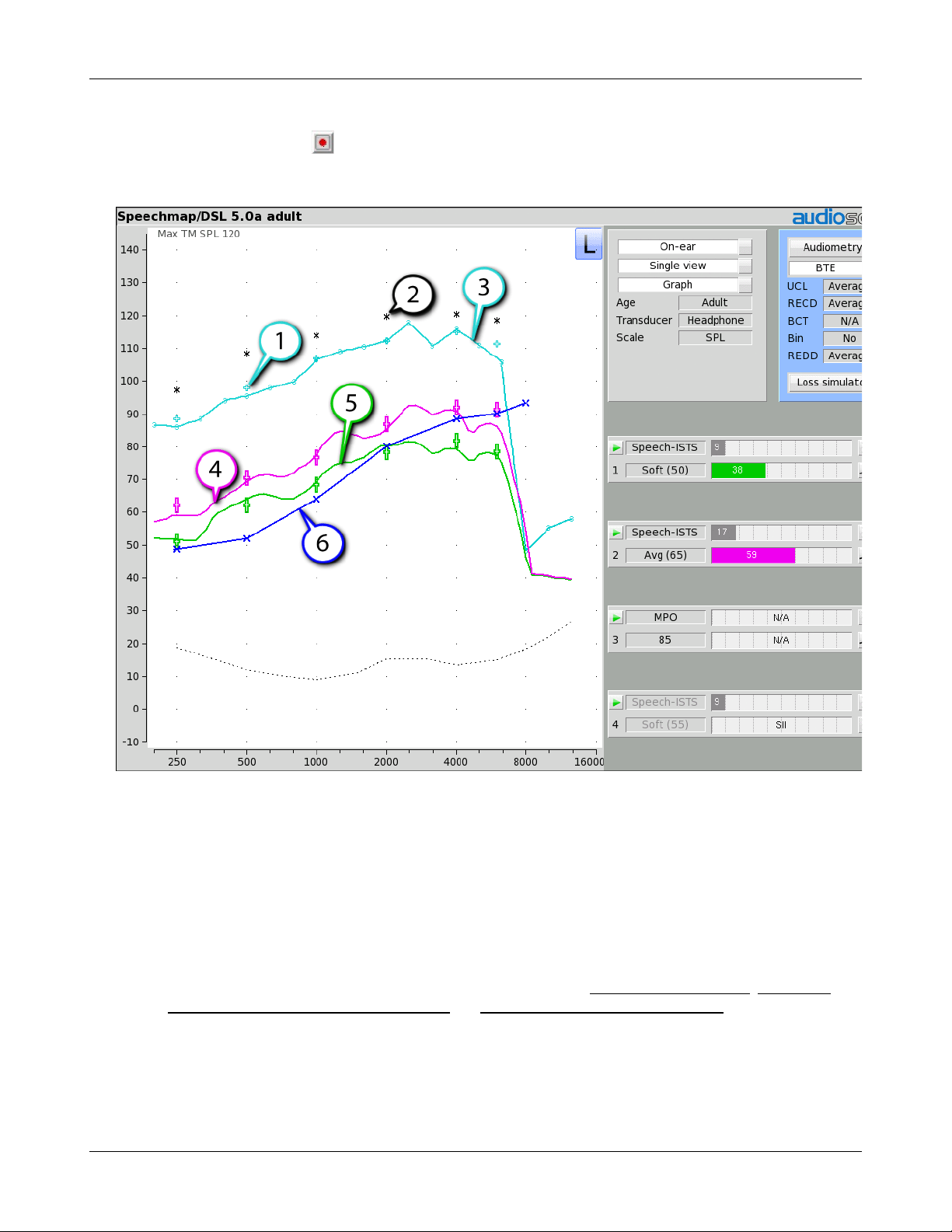
Verifit®User's Guide Version 4.2 © June 2015
4. In On-ear mode, advise the client to point to the screen if a sound becomes too loud during the test (see Max
TM SPL setup). Click to run and record a single sweep. Adjust the gain and output for loud sounds as for
test box measures, factoring in client response. Note: MPO stimulus is run at 85dB for On-ear mode, and
DSL REAR90 targets are adjusted accordingly.
1. DSL REAR90 target, 2. Estimated UCL, 3. Measured MPO, 4. LTASS 65, 5. LTASS 40, 6. SPL Threshold
Open fittings in Speechmap
On-ear mode should be used for open and vented fittings. There are no special real-ear SPL targets for open
fittings - it doesn’t matter how the sound reaches the TM, the perception is the same. However, the sound that
escapes from a vent or open fitting may be detected by the on-ear reference microphone, interfering with the
sound-field equalization. For this reason, the hearing instrument must be muted during sound-field equalization.
1. With Speechmap in the [On-ear] mode, click the Instrument pull-down menu and select [Open] .
2. Position the client and probe tube and enter audiometric data. See On-Ear Measures - Setup, Speechmap, and
Fitting to targets for soft and average speech and Adjusting the Maximum Output Level.
3. Place the open-fit hearing instrument on the ear with the probe tube in place, making sure to mute the
hearing instrument.
4. Access Test 1, 2, 3 or 4. If this is the first test since selecting Open, you will be prompted to mute or turn off
the hearing instrument and click the Equalize button on the setup poster. After equalization, unmute or turn
60
Verifit®User's Guide Version 4.2 © June 2015
the instrument on and follow the fitting procedures presented previously in this section. It is necessary to
repeat the Equalize procedure whenever the client or nearby objects are moved.
Verifying Frequency Compression/ Frequency-Lowering Hearing Instruments in Speechmap
Frequency lowering is used when it is not possible to amplify the high frequency components of speech
sufficiently to raise them above threshold. In this case, the high frequency components may be shifted to a
lower frequency with a better hearing threshold where the available gain will render them audible.
Four modified versions of a calibrated speech test stimulus (Speech3150, Speech4000, Speech5000 and
Speech6300) are provided in Speechmap to assist in verifying and adjusting frequency lowering devices. In
each of these modified test stimuli, the 1/3 octave band levels above 1000Hz are reduced by 30dB, except for an
isolated 1/3 octave band centered at the frequency indicated in the selected test stimulus’ name. With these
reduced band levels, the resulting LTASS produces a distinct 'cavity' between 1000Hz and the selected high
frequency band, as seen below for the FM Boom test signal.
To test frequency-lowering:
1. Right click to show the home menu and choose Speechmap from either the On-ear or Test box columns.
2. Program the hearing instrument so that the frequency-lowering feature is inactive.
3. Access Test 1, 2, 3 or 4 by clicking on the appropriate to start that test.
4. Choose Speech3150, Speech4000, Speech5000 or Speech6300 from the Stimulus pull-down menu. Choose
65dBSPL from the Level pull-down menu. Note that only the LTASS is shown for these stimuli and targets
(if selected) have been suppressed.
5. Click to measure and store the long-term signal-averaged result. If the isolated band does not appear in
the Test 1 curve, it may indicate that the hearing aid has no gain at the selected band frequency. This does
not mean that the hearing aid will be unable to transpose the band to a lower frequency when frequency
lowering is enabled.
6. Program the hearing instrument to activate the frequency-lowering feature.
7. Click another and select the same stimulus and stimulus level used in Test 1.
8. Click to measure and store the long-term signal-averaged result.
9. The isolated band should now appear at a lower frequency and should reach or exceed threshold at its new
location as shown below. Note that the 'cavity' between 1 kHz and the isolated band may be partially or
completely filled in by noise within the hearing aid which will make the isolated band appear less distinct in
the test curves.
10.Once the frequency-lowering properties of the hearing instrument have been verified, use one of the
calibrated speech stimuli to verify aided speech audibility or target match (as described elsewhere in this
section) for frequencies below the isolated band.
61

Verifit®User's Guide Version 4.2 © June 2015
1. LTASS Speech-std(F), 2. LTASS Speech4000, 3. LTASS Speech5000, 4. LTASS Speech6300
Binaural fitting in Speechmap
When Speechmap is set to Dual view, it is possible to analyze both left and right hearing instruments
simultaneously.
1. Follow the instructions in Speechmap screen choices to enter audiometric data and select the fitting rule.
2. Click L+R button until both L and R are colored.
3. Click in any of the test areas to start test. The stimulus and level will be presented to both ears
simultaneously.
4. Once the test is started, click the [Stimulus] list button to select the stimulus type from one of the calibrated
speech stimuli. Click the [Level] list button and select a stimulus level.. When you start a new test, the
speech envelopes of the previous test may be automatically hidden. See Speechmap Setup to change this
behaviour. To change the default stimulus type and level see Saving test setup.
5. While the passage is being presented, adjust the hearing instrument's frequency shaping and gain for average
sounds so that the middle curve (the LTASS) falls within the target range, shown by the symbols,
especially between 500 - 4000 Hz. These target symbols are automatically adjusted for the stimulus level you
select.
6. Click to signal average and store a complete passage. Repeat as necessary.
62

Verifit®User's Guide Version 4.2 © June 2015
7. Click to stop the test without recording any test data.
8. In Test box mode, all stimuli are available for simultaneous binaural testing. In On-ear mode, only Speech-
live is available. To measure two hearing aids simultaneously, the stimulus must be equalized at both
microphones. This is only physically possible in the controlled acoustic environment provided by the
binaural test box.
CROS fitting in Speechmap
See Using Speechmap.
1. Place a probe module on each ear and insert the probe tube into the good ear only. Position the CROS
instruments on (in) the ears and turn them ON.
2. Position the speaker at 45 degrees to the good ear and set Instrument to [BTE].
3. Click in test 1 area to start test and record a response using [Pink noise] at Soft (55). It should be like a
normal REUR. If not, the ear may not be fully open.
4. Position the speaker at 45 degress to the poor ear.
5. Set Instrument to [CROS].
63

Verifit®User's Guide Version 4.2 © June 2015
6. Click in test 2 to start test and obtain a response using [Pink noise] at Soft (55). Adjust the response to
match that obtained in step 3.Position the speaker directly in front of the client. Click in test 3 area to
start test and use [Pink noise] at Soft (55) to check for a smooth response. Repeat with Instrument set to
[BTE]. An irregular response may be the result of reflections from nearby objects (including the operator) or
it may indicate phasing problems in the aids.
T-Loop fitting and verification in Speechmap
This test allows the T-Loop response of the hearing instrument to be measured so that it can be compared
against a 65 dB SPL acoustic response.
1. Set the instrument to 'T' (Telecoil input).
2. Click in any of the test areas to start test and select one of the calibrated speech stimuli.
3. Change the level to T-Loop (65). This will result in a T-Loop signal equivalent to a 65 dB SPL acoustic
stimulus.
4. Click to measure and store the long-term averaged result. The result can be directly compared against a
65 dB acoustic response, as shown below.
Note: The TL(65) stimulus level produces a magnetic field strength of 56.2 mA/m which, for a hearing aid
operating linearly, is equivalent to the IEC specification (70dB SPL = 100 mA/m) and the ANSI specification
(60 dB SPL = 31.6 mA/m).
64
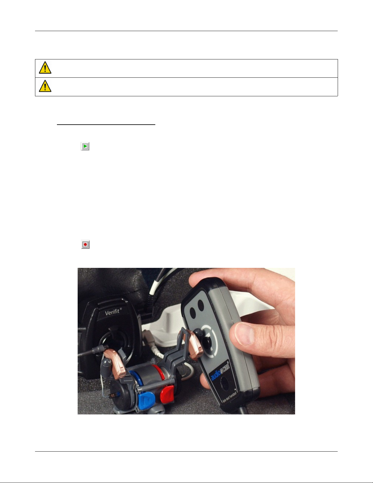
Verifit®User's Guide Version 4.2 © June 2015
Tele-test fitting and verification in Speechmap
WARNING: The included magnet may effect some medical or electronic devices. Keep magnet at least 5cm
(2in.) from implantable devices and other magnetically sensitive devices.
WARNING: Keep magnet out of reach of children and pets. If a magnet is swallowed seek immediate medical
attention.
This test allows the telecoil response of the hearing instrument to be measured so that it can be compared against
a 65 dB SPL acoustic response. In addition, auto-coil, binaural coordination and binaural streaming features can
be verified. The tele-test handset comes with a small magnet attached that may affect implantable devices. See
How to Avoid Undesirable Side Effects.
1. Set the instrument to 'T' (Telecoil input) or enable the auto-coil feature.
2. Click in any of the test areas to start a test and select one of the calibrated speech stimuli.
3. Change the level to Tele-test (65). This will result in an inductive signal from the Tele-test handset
equivalent to 65 dB SPL acoustic stimulus when positioned close to the hearing instrument.
4. If using an auto-coil feature, attach the switching magnet provided with the hearing instrument (or an
Audioscan switching magnet) to the Tele-test handset in the marked position appropriate for the hearing
instrument.
5. Position the Tele-test handset within 1 cm of the hearing instrument such that the front face of the Tele-test
handset is parallel to the height of the hearing instrument (e.g. like holding a telephone handset or
cellphone).
6. Activity on the graph indicates that the hearing instrument is receiving the inductive stimulus.
7. Click to measure and store the long-term averaged result. The result can be directly compared against a
65 dB acoustic response.
65

Verifit®User's Guide Version 4.2 © June 2015
FM fitting and verification
FM Offset or FM Transparency method in Speechmap (after Platz 2004)
It is assumed that the hearing aid has been set up for optimal audibility and maximum output. See Speechmap
screen choices for setup and audiometric data entry. See Using Speechmap
1. Before attaching the FM receiver, couple the hearing aid to one of the 0.4cc couplers in the test box, right
click and select Speechmap from the Test box menu.
2. In the Audiometry section, select the hearing aid type from the list. (typically BTE).
3. Click in test 1 area, then choose one of the calibrated speech stimuli at a Level of 65 dB. Click to
run and record the speech passage.
4. Attach the FM receiver to the hearing aid and set the FM receiver to the default setting. The FM transmitter
should be ON and set to MUTE. Repeat step 2 but use Test 2 instead of Test 1. If the results of Test 1 & Test
2 are not similar, the presence of the FM receiver has changed the intended performance of the hearing aid.
Where possible, make programming adjustments to compensate -being careful not to make adjustments that
will change Test 1 results.
5. Move the hearing aid, attached to the coupler and microphone, outside the test box at least 12' away from the
FM transmitter*. Put the FM transmitter microphone, set to Omni, within 2mm of the test box reference
microphone corresponding to the coupler used in step1. Close the lid of the box.
6. With the FM transmitter unmuted, repeat step 2. Note that the hearing aid is outside the test box during this
test - Quiet please! The results should be within +/- 2 dB of the results from step 3. If not, change FM
settings and repeat.
* A coupler mic. extension cable is available. See Microphone connection.
Real-ear verification of FM-only open fittings in Speechmap (based on AAA Clinical Practice Guidelines:
Remote Microphone Hearing Assistance Technologies for Children and Youth from Birth to 21 Years. April
2008)
Open fittings must be verified in On-ear mode. See Speechmap screen choices for setup and audiometric data
entry. See Using Speechmap
1. Enter Audiometry data.
2. In the Audiometry section, and select the FM hearing aid type from the list.
3. Position the transmitter microphone as in step 4 above. Place the probe tube in the ear canal and couple the
FM-only device to the ear canal as in normal use.
4. At maximum volume setting, select the MPO stimulus. Adjust the receiver settings to meet targets. See
Adjusting the Maximum Output Level.
5. At use volume setting, select one of the calibrated speech stimuli and choose FM chest (84 dB SPL) or FM
boom (93 dB SPL) for the level. Adjust the FM receiver gain/volume settings to meet targets in the 1000 –
4000 Hz range.
6. Repeat step 3 at use volume setting.
How to Verify with Calibrated 'S' and 'SH' Stimuli
Why verify with phonemic-like stimuli?
66

Verifit®User's Guide Version 4.2 © June 2015
/sh/. They also may support phonemic analysis of hearing aid responses. They are not meant to replace current
verification protocols used to verify conventional hearing aid fittings, but are meant to supplement your
verification procedures, particularly in the cases of extended bandwidth and/or frequency lowering.
How were the stimuli created?
Instances of /s/ and /sh/ were identified within the ISTS passage, which is based on female speech, to create a
target spectrum per phoneme. A simulated version of "S" and "SH" was then created using shaped noise to
simulate the target spectrum for each phoneme. The resulting stimulus files are each 5 seconds long.
1. Verify the frequency shaping and output of the fitting without frequency lowering to ensure best audible
bandwidth of speech from gain & WDRC alone. The steps below have been developed with the DSL v5
target as the base fitting method.
2. Start the "S" stimulus at a presentation level of 65 dB SPL. Determine whether the stimulus is within the
listener’s auditory area. If not, complete the steps below.
3. Enable a frequency lowering signal processor. Start with the default frequency lowering setting. The "S" will
"loop", so you can keep it playing continuously while you fine tune the frequency lowering signal processor
as needed. Lower the "S" in frequency until it is audible.
4. Start the "SH" stimulus at a presentation level of 65 dB SPL. Determine whether it is audible, and also
whether it has some frequency separation from the "S" stimulus. If they are overlapping, the listener may
have difficulty perceiving them as two different speech sounds. Fine tune as needed.
(a) Exact target levels for individual phonemes are not yet established.
(b) Because the ''S'' and ''SH'' stimuli are much broader in frequency than a pure tone, some listeners may
detect the stimuli at levels that are near their pure tone thresholds.
5. Perform a listening check, considering whether the sound quality and distinction of "S" and "SH" in speech
are acceptable. At the time of fitting and follow up, consider the listener’s responses, therapist feedback, and/
or outcome measurements that provide insight into the perceived sound quality and ability to distinguish "S"
and "SH".
67

Verifit®User's Guide Version 4.2 © June 2015
9 Speechmap Technical Details
The following sections outline the principles underlying Speechmap stimuli and measurements, especially for
wideband tests.
Wideband measurements in Speechmap
The availability of hearing instruments claiming to provide amplification above 8 kHz, and the reported benefit
of those wider bandwidths for young children has motivated Audioscan to extend the bandwidth of the Verifit to
16 kHz which encompasses the 12.5 kHz third octave band. This necessitated several significant advances:
1. Microphones with a flat response to 16 kHz and a low noise floor and development of production calibration
processes.
2. A 0.4cc coupler to overcome standing wave problems in the 2cc coupler and increase the signal level.
3. Digitized speech stimuli with measurable energy to 16 kHz.
4. A Wideband RECD (WRECD) measurement protocol based on the 0.4cc coupler and improved to reduce
errors associated with the effects of earmold and coupler tubing.
5. Provisions for threshold and WRECD entry to 12.5 kHz.
6. Conversion of entered and normative RECD values to WRECD values for frequencies below 8 kHz.
7. Derivation of Microphone Location Effects (MLE) to 12.5 kHz.
Speechmap stimuli
Speechmap provides a variety of stimuli for the testing of non-linear hearing aids with a range of digital
processing features.
The Speechmap fitting environment provides a number of well-controlled, distinctly different stimuli for both
On-ear and Test box measurement modes. Several different digitized speech passages are provided as well as
the International Speech Test Signal (ISTS) and the single-talker International Collegium of Rehabilitative
Audiology (ICRA) distorted speech signal. Two speech passages have been filtered to provide the same longterm average speech spectrum (LTASS) as the ISTS for average vocal effort. In addition, one of these passages
has been filtered to suppress the 1/3 octave bands above 1 kHz by 30 dB with the exception of a 1/3 octave band
at 3.15 kHz (Speech 3150), a band at 4 kHz (Speech4000), a band at 5kHz (Speech5000) and a band at 6.3 kHz
(Speech6300). These latter signals may be used to determine the amount of frequency shift provided by
frequency-lowering hearing aids and the sensation level of the lowered components of the speech signal. Pink
noise at levels of 50 to 75 dB SPL in 5 dB steps and a tone burst at 85 or 90 dB SPL are also available. The
ICRA noise, female and child speech signals are presented as recorded with no spectral shaping.
The ISTS consists of 500 ms segments from recordings of 6 female talkers reading the same passage in
American English, Arabic, Chinese, French, German and Spanish. These segments have been spliced together
with appropriate pauses and filtered to match the average female spectrum from Byrne et al, An international
comparison of long-term average speech spectra. J. Acoust. Soc. Am. 96 (1994), 2108-2120. The 15 second
version of this signal has been provided.
Live speech may also be used.
The speech, ISTS and ICRA signals are presented unfiltered for levels from 50 to 70 dB SPL. At 75 dB SPL, the
spectrum is filtered to represent a 'loud' vocal effort. An 'own voice' filter is also available at the 75 dB SPL
level. This is intended to produce a spectrum and level at a BTE microphone location similar to that produced
by the voice of an average wearer.
68

A tone burst (MPO) stimulus provides 128 ms bursts with 128 ms gaps at 1/3 octaves with a level of 90 dB SPL
3 5
4 0
4 5
5 0
5 5
6 0
6 5
2 0 0 2 5 0 3 1 5 4 0 0 5 0 0 6 3 0 8 0 0 1 0 0 0 1 2 5 0 1 6 0 0 2 0 0 0 2 5 0 0 3 1 5 0 4 0 0 0 5 0 0 0 6 3 0 0 8 0 0 0 1 0 0 0 0 1 2 5 0 0 1 6 0 0 0
F r e q u e n c y ( H z )
1 / 3 o c t a v e b a n d S P L f o r s p e e c h a t 7 0 d B S P L f r o m B y r n e e t a l ( 1 9 9 4 ) a n d
C o x & M o o r e ( 1 9 8 8 )
M a l e F e m a l e / I S T S C o m b i n e d / I L T A S S C o x & M o o r e
in the test box and 85 dB SPL for on-ear mode.
In test box mode, all signals are filtered to include BTE, ITE, ITC, CIC, Body microphone location effects. The
selected overall rms level is established prior to filtering.
For fitting FM systems, the stimuli may be modified to represent the level (84 dB SPL) and spectrum at a chest
microphone location and the level (93 dB SPL) and spectrum at a boom microphone location. These are
presented in the test box in both on-ear and test box modes.
The overall SPL, 1/3rd octave band SPL, vocal effort and microphone location effects are given in the following
tables for the various broad-band signals available.
Stimulus spectra
Speech signals calibrated for matching to targets have the same LTASS as the ISTS. Modification for Loud
spectrum is from ANSI S3.5-1997. Modification for Own voice spectrum is from Cornelisse et al (1991)
adjusted to a 1 m reference.
The LTASS of the ISTS is the average female spectrum from Byrne et al (1994), which differs less than 2 dB
from the universal LTASS (or International LTASS) suggested in this paper and less than 2 dB from the LTASS
of Cox & Moore (1988). For all practical purposes, they are equivalent.
Verifit®User's Guide Version 4.2 © June 2015
69

Verifit®User's Guide Version 4.2 © June 2015
1/3 octave band SPL Add to band SPL for
Speech
Hz Calibrated Female Child
200 57.6 54.6 39.4 53.3 52.2 9.6 -3.0 6.3 16.5
250 56.3 53.7 52.7 55.4 52.2 10.7 3.1 11.7 21.9
315 53.5 49.7 56.5 55.9 52.2 10.9 9.1 16.5 25.5
400 57.1 55.4 54.1 57.4 52.2 10.0 6.0 13.5 22.7
500 57.1 57.2 55.1 57.3 52.2 10.1 8.6 13.8 26.2
630 55.8 58.0 60.6 55.1 52.2 10.5 11.6 21.4 28.3
800 53.4 54.8 56.2 52.3 52.2 10.8 13.5 26.0 31.2
1000 49.7 52.3 53.4 50.4 52.2 10.1 16.3 26.9 34.0
1250 47.7 50.6 45.1 48.5 52.2 4.4 17.7 22.2 36.4
1600 47.1 52.0 41.7 46.5 52.2 4.2 16.4 22.2 34.8
2000 44.2 50.7 39.3 44.3 52.2 5.9 17.0 20.9 33.8
2500 42.7 48.7 35.2 41.9 52.2 5.6 16.1 18.2 33.2
3150 42.1 48.0 30.0 40.5 52.2 1.7 14.9 13.8 30.8
4000 40.7 40.8 3105.0 38.7 52.2 -0.6 14.5 12.2 30.3
5000 40.0 36.0 30.7 36.8 52.2 -1.1 9.2 13.0 27.8
6300 40.6 40.9 33.1 35.0 52.2 -0.2 5.1 11.3 27.1
8000 40.3 39.6 34.9 33.1 52.2 -3.8 3.9 11.9 27.7
10000 40.4 28.0 34.1 31.4 52.2 -7.1 2.3 10.7 26.5
12500 38.2 22.6 31.3 29.9 52.2 -10.6 3.1 9.7 25.5
Overall 65 65 65 65 65 75 75 84 93
The above values may differ slightly from previous software versions due to reanalysis of all stimuli and
modifiers using newer equipment and analysis software.
ICRA
Noise
Pink
Noise
Loud
Own
VoiceFMChestFMBoom
Microphone location effects
Microphone location effects (MLE) for BTE, ITE, ITC and CIC aids were measured in an anechoic chamber on
a KEMAR manikin relative to a microphone location on the cheek below the earlobe. The MLEs in the
following table are added to the stimulus after the overall rms level has been set.
Deep insertion compensation
The deep insertion of a hearing aid or ear-mold causes the ear canal SPL to be higher than would be estimated
by adding and RECD or WRECD to the coupler SPL measured in the test box. This most commonly occurs with
Completely-in-Canal (CIC) hearing aids. When this hearing aid type is selected in Speechmap Test box, a deep
insertion factor is automatically added to the estimated ear canal SPL. The factor in the following table is from
DSL 5.0 and has been interpolated to 1/3 octave frequencies and extrapolated for frequencies above 6 kHz.
70

Verifit®User's Guide Version 4.2 © June 2015
Microphone Location Effects Deep Insertion
Add to all stimuli in test box mode Add to Est. Canal SPL
Hearing instrument type
Frequency BTE ITE ITC CIC BODY CIC
200 0 0 0 0 3.0 1.9
250 0.3 1 0.9 1.3 3.0 1.9
315 0.7 1.3 1.2 1.8 3.0 2.6
400 0.2 0.8 0.8 1.2 3.0 3.3
500 -0.1 0.8 1 1.3 4.0 4.0
630 -1.7 -0.3 -0.2 0.2 3.0 4.6
800 -2 -0.6 -0.4 0.1 2.0 5.2
1000 -2.2 -1.1 -0.9 -0.4 0 5.8
1250 -0.3 -0.6 -0.5 0 0 6.0
1600 4.9 3.9 3.7 4.2 -4.0 6.1
2000 6.1 6.9 6.9 8.1 -4.0 6.1
2500 1.8 5.1 5.5 7.4 -3.0 6.4
3150 -0.4 2.7 2.9 5.7 -2.0 6.6
4000 0.2 6 4.8 8.6 0.0 7.7
5000 2.6 10.4 7.9 12.7 0.0 8.1
6300 3 5.2 1.2 9 0.0 8.4
8000 3.7 -1.6 -0.4 3.5 0.0 8.4
10000 3.7 1.6 4.6 0.8 0 8.4
12500 2.3 2.2 3.3 3.2 0 8.4
Speech signal analysis
One of the most-used measures of a speech signal is the long-term average speech spectrum (LTASS). This is a
1/3 octave spectrum averaged over a sufficiently long portion of the speech material to provide a stable curve. In
practice a 10 second average meets this requirement and, for this reason, all Verifit passages are at least 10
seconds long.
The dynamic nature of speech is often characterized by the distribution of short-term levels in each 1/3 octave
band. These levels are determined by calculating a spectrum for each of a series of short time periods within the
passage. Historically, time periods of 120, 125 or 128 ms have been used. The Verifit uses a 128 ms time period,
resulting in 100 levels (or samples) in each 1/3 octave band for a 12.8 second passage. The level in each band
that is exceeded by 1% of the samples (called L1 or 99th percentile) has historically been referred to as the
speech peak for that band. The curve of the 99th percentile is approximately 12 dB above the LTASS. The level
in each band that is exceeded by 70% of the samples (called L70, or 30th percentile) has historically been called
the valley of speech for that band. The curve of the 30th percentiles is approximately 18 dB below the LTASS.
The region between these two curves is often called the speech region, speech envelope or speech 'banana'. The
speech envelope, when derived in this way, has significance in terms of both speech detection and speech
understanding. Generally, speech will be detectable if the 99th percentile is at or near threshold. The Speech
Intelligibility Index (SII) is maximized when the entire speech envelope (idealized as a 30 dB range) is above
(masked) threshold. This will not be an SII of 100% (or 1) because of loudness distortion factors, but higher SII
values will not produce significantly higher scores on most test material. The speech-reception threshold (SRT)
is attained when the LTASS is at threshold (approximately - depending on test material and the individual).
71

Verifit®User's Guide Version 4.2 © June 2015
10 On-Ear Instrument Measures
A number of the tests covered in Test box measures can also be performed with the hearing instrument coupled
to the ear of a client rather than to a coupler. The on-ear results may be expected to differ from the test box
results because of the different acoustic environment and the different acoustic load.
On-ear directional test overview
Directional characteristics such as polar plots and Directivity Index (DI) are typically measured in a large
anechoic chamber using sound from one direction and at one frequency at a time. This means they apply only
for a hearing aid set for linear amplification. These are not conditions representative of real use. The Verifit
directional test measures directional performance in real-time while using speech. It is compatible with all forms
of hearing aid processing, including frequency lowering, feedback compensation, and other non-linear
algorithms.
The Verifit directional test presents speech at selectable levels from the front speaker and noise, at a selectable
signal-to-noise ratio, from the rear speaker. At periodic intervals, the level of the speech and noise is
momentarily reduced and an additional burst is played from either the front or rear speaker to measure the
response from that direction. This burst is extremely fast and will not influence the behavior of the hearing aid.
The coupler SPL is analyzed into two curves labeled F (front) and B (back) to indicate which speaker generated
the curve. The real-time nature of the test allows the operation of adaptive directional systems to be readily
visualized.
Optionally, speech can be disabled which will cause the directional test to alternate noise bursts from the front
and back speakers. This test may not produce a directional response with all hearing aids.
Once directional performance is observed, the test may be terminated.
Because this measurement is carried out in a real room, results are not expected to agree with data taken in large
anechoic chambers. Due to strong reflected signals, measurements made in small reverberant rooms will show
small separation between front and back response curves, just as the benefits of directional technology will
become less apparent in similar situations. When performed in a sound booth or large acoustically 'dead' room,
this test can be used to demonstrate and verify directional benefit and to provide assurance that the directional
microphone array has been correctly assembled and programmed and has not deteriorated due to element drift or
the clogging of ports.
On-ear directional testing
Best results are obtained using external front and rear sound-field speakers positioned well away from reflective
surfaces. See External sound-field speaker setup. Refer to On-Ear Measures - Setup to prepare the system for use
and for proper positioning of the client and the probe tube.
1. Insert the earmold or custom hearing instrument into the ear, being careful not to advance the probe tube
further into the ear canal. A lubricant applied in the vicinity of the probe tube will ease insertion and prevent
slit leaks.
2. Right-click mouse to raise Home prompt and select [Directional] under On-ear.
3. Left-click Test 1, 2, 3 or 4. Two real-time curves appear on the screen - the heavier one is the response to the
front speaker signal and the lighter one the response to the back speaker signal. The two curves will be
nearly identical for a non-directional instrument in a sound booth or acoustically 'dead' room. Setting the
instrument for directional operation should produce a separation of the curves.
4. On the Test control poster, click the Level window and select a level from the drop-down list. For an
adaptive directional instrument, a stimulus level between 60 and 70 dB should cause the separation to change
72

Verifit®User's Guide Version 4.2 © June 2015
over a 15 – 45 second period. For a noise-reducing instrument, both curves may change with time and
stimulus SPL.
5. Click [Speech S/N] within the Test control poster and select a signal to noise ratio from the list box. A S/N
ratio between 0 and 6 dB will usually induce directional performance after 15 – 45 seconds. Optionally, click
[Speech S/N] and select Off. This presents noise alternating between the front and back test speakers.
Speech-adaptive directional instruments may appear non-directional if [Speech S/N] is Off .
6. Press to capture curves or press to abort the test. Captured curves are labeled F (front speaker
response) and B (back speaker response) followed by the test number (1 - 4).
On-ear feedback test
This test shows the LTASS (upper graph) and the power concentration ratio (PCR) (lower graph) for a speech
signal. The PCR measures the degree to which a large amount of power is concentrated at a small number of
frequencies in the hearing aid output (see Freed & Soli in References). In the Verifit, the PCR is the ratio of the
average power of the dominant frequency components in a 1/12 octave band to the power in the entire band,
expressed in dB. Because the gain of a compression hearing aid varies with the signal it is processing, the PCR
is calculated in real time while a speech signal is presented to the hearing aid. The upper graph shows the
LTASS for the speech signal while the lower graph shows the PCR relative to the PCR for speech without
feedback. Feedback results in a peak in the speech spectrum and in the PCR. Incipient feedback results in a
peak in the PCR curve.
Refer to On-Ear Measures - Setup to prepare the system for use and for proper positioning of the client and the
probe tube.
1. Insert the earmold/tip or custom hearing instrument into the ear, being careful not to advance the probe tube
further into the ear canal. A lubricant applied in the vicinity of the probe tube will ease insertion and prevent
slit leaks.
2. Set the instrument as it will be used, with feedback suppression enabled and initialized.
3. Right-click the mouse to raise the Home prompt and select [Feedback] under On-ear.
4. Left-click Test 1 and set the Stimulus to Speech-std(1) or (2) and the level to 50 or 60 dB SPL. As the speech
passage plays, observe the feedback bar and the lower graph. A yellow Feedback bar and peaks with yellow
markers in the lower curve indicate incipient feedback which may impact sound quality. A red Feedback bar
and peaks with red markers in the lower curve indicate feedback that may be audible and should be
mitigated. Click to run the full speech passage and capture average results for the passage.
5. Repeat for Test 2 and 3 as needed. These tests may be used to explore the effects of jaw movement and the
presence of hands, hats and telephone handsets.
On-ear noise reduction test
This test captures a response curve before the hearing instrument reacts to the presence of noise; a comparison
curve shows the hearing instrument reacting in real-time. The thick curve is the output before the noise
reduction is activated and the thin line is the output as the noise reduction takes effect. The test also provides an
overall rms noise reduction value in dB.
Refer to On-Ear Measures - Setup to prepare the system for use and for proper positioning of the client and the
probe tube.
1. Right-click the mouse to raise the Home prompt and select [Noise reduction] under On-ear.
2. Click Test 1, 2 or 3.
73

Verifit®User's Guide Version 4.2 © June 2015
3. Select a stimulus type from the list box.
4. Select a stimulus level from the list box.
5. Click [Start test]
6. Click to capture the comparison curve once the noise reduction function has responded.
On-ear manual control
1. Refer to On-Ear Measures - Setup to prepare the system for use and for proper positioning of the client and
the probe tube.
2. Right-click the mouse to raise the Home prompt and select [Manual control] under On-ear.
3. Click the Level window, then select the desired stimulus level from the drop-down list.
4. Click the Frequency window, then select the desired frequency from the drop-down list. (Distortion
measurement data is available only from 200-2500 Hz.)
5. Click [Start test] to start the test. [Start test] changes to [Stop Test]. To stop the measurement, click [Stop
test]. You may change Level and Frequency without stopping the test.
Sound level meter using on-ear microphones
The manual control feature enables the Verifit to be used as a sound level meter to perform C-weighted, Aweighted or 1/12th octave analysis of sound as measured by the probe and reference microphones. A and Cweighted measurements are limited to frequencies above 100 Hz and the averaging time and update rate are 384
ms.
1. Refer to On-Ear Measures - Setup to prepare the system for use and for proper positioning of the client and
the probe tube.
2. Right-click the mouse to raise the Home prompt and select [Manual control] under On-ear.
3. Click the Level window, then select 0 dB stimulus level from the drop-down list.
74

Verifit®User's Guide Version 4.2 © June 2015
4. Click the Filter window, then select 1/12th octave, A-weighted, or C-weighted from the drop-down list.
5. For 1/12th octave filter, click the Frequency window, then select the desired frequency from the drop-down
list.
6. Click [Start test] to start the test. [Start test] changes to [Stop Test]. To stop the measurement, click [Stop
test]. You may change Level and Frequency without stopping the test.
75
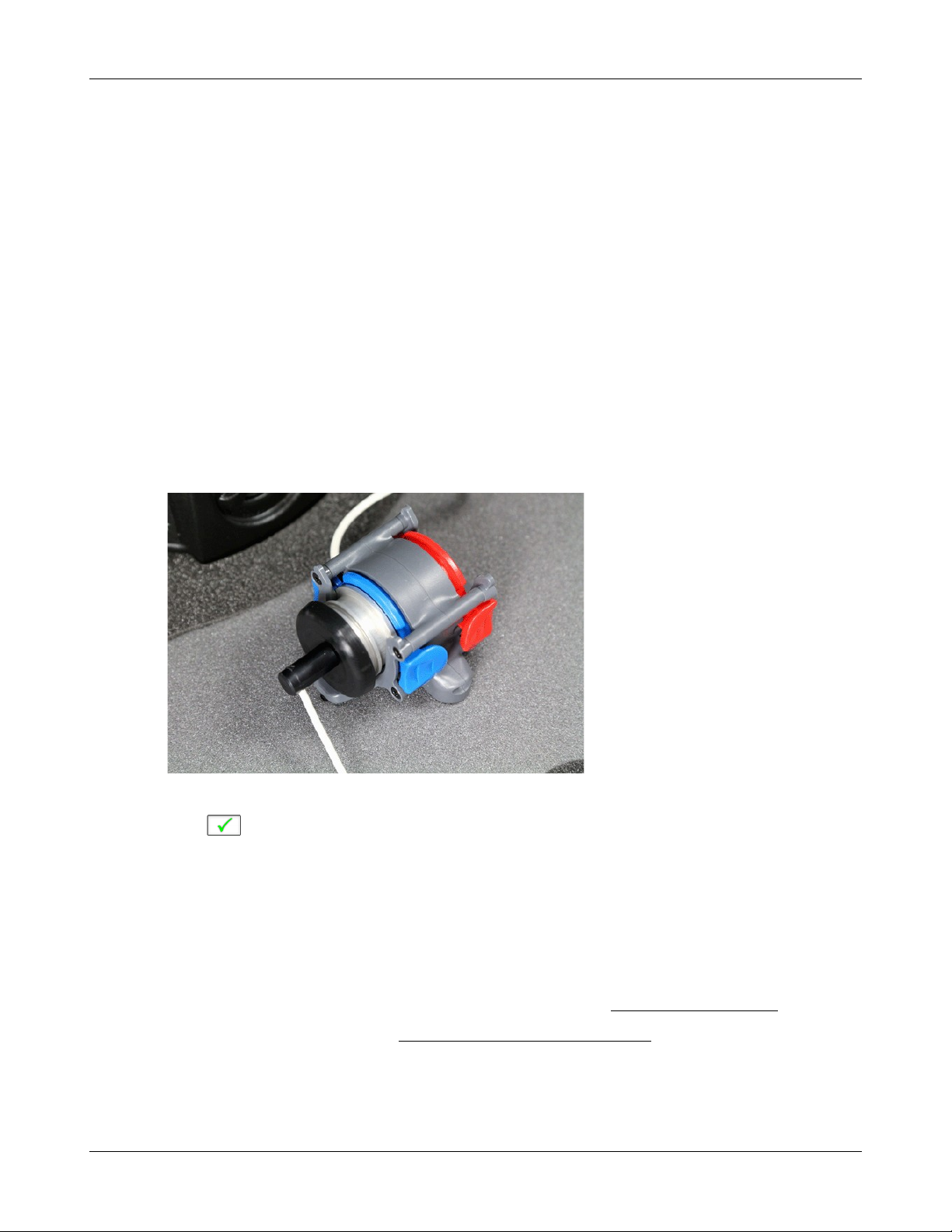
Verifit®User's Guide Version 4.2 © June 2015
11 WRECD measurement
The WRECD (Wideband Real-Ear to Coupler Difference) may be individually measured to improve the
accuracy of hearing aid fittings. The measurement procedure may be accessed by selecting WRECD from the
On-ear tests list on the home menu or from the Audiometry poster within Speechmap.
Calibration of WRECD Transducer
WRECD values are stored and expressed as referenced to the 0.4 cc wideband coupler. A calibration of the
Audioscan RECD transducer in this coupler is required at a minimum of weekly.
1. Connect the WRECD transducer to the WRECD jack on the Probe Dock. Prepare the system for test box
tests. See Microphone connection, Calibrating test box reference microphone.
2. Choose WRECD from the On-ear list on the home menu.
3. Select the RECD coupling method that will be used on the ear. Audioscan software supports both foam
eartips and personal earmold, however this choice must be made prior to measurement.
4. Attach the TRIC adapter to the 0.4cc coupler and attach this to the blue coupler microphone.
5. Insert the nozzle of the WRECD transducer all the way into the opening of the TRIC.
6. Click . This causes a broadband signal to be applied to the WRECD transducer and the 0.4cc coupler
SPL to be recorded and displayed.
7. Select Interval to toggle the measurement interval for the coupler response between daily and weekly. If
set to weekly, RECD transducer calibration will expire at 12 AM Monday morning.
Measure WRECD
Connect the RECD transducer to the RECD jack on the Probe Dock. See WRECD coupler response.
Prepare the system for on-ear tests. See Calibration of on-ear probe microphone.
1. Select [WRECD] on the home menu.
76

Verifit®User's Guide Version 4.2 © June 2015
2. Select the WRECD coupling method that will be used on the ear. Audioscan software supports both
foam eartips and personal earmolds, however this choice must be made prior to measurement.
3. If no RECD calibration exists or the measurement interval has been exceeded, go to 15.3: Calibration of
WRECD transducer. If a valid transducer calibration exists, select [Measure real ear].
4. Couple a standard insert earphone foam eartip to the nozzle of the WRECD transducer. If using an
earmold, seal any vent at its outer surface.
5. Refer to Positioning the probe tube and insert the probe tube into the ear canal to within 2 - 5 mm of the
eardrum.
6. Insert the foam tip or earmold into the ear, being careful not to advance the probe tube further into the ear
canal. Insertion depth should be as used with insert phones. Allow the foam tip to fully expand in the ear.
Insertion depth should be as used with insert phones.
7. Select to generate the real-ear response curve (magenta) and the WRECD curve (blue). If the WRECD
curve is negative and unstable in the low frequencies, check the seal of the foam tip. Increase the tip size
and/or apply a lubricant to the foam tip to improve the seal. If the WRECD curve deviates more than 10 dB
from the average in the 4 - 6 kHz region, check for proper probe placement and possible blockage of the tube
by the foam tip or cerumen.
8. When these curves are stable, select to save them.
For comparison purposes, the age-related average WRECD is shown as a dotted curve on the screen. If you have
accessed WRECD from the main menu, you may click the Age box to change the age for this reference curve.
77

WRECD results
The WRECD measurement screen shows the response of the WRECD transducer in the 0.4cc coupler (1)
and in the real ear (2). The difference between these curves is the WRECD (3). The age-appropriate
average WRECD is shown for reference (4).
Since WRECD uses the 0.4cc coupler rather than 2cc, it is normal to see negative numbers since the volume
of the wideband coupler more closely matches that of an ear. A WRECD with large negative slope in the
low frequencies may indicate a poor seal between the foam tip and the ear canal, or an open vent in an
earmold. A negative WRECD above 1 kHz often indicates a blocked or pinched probe tube. See WRECD
facts.
Verifit®User's Guide Version 4.2 © June 2015
WRECD protocols
To facilitate wideband Test box Speechmap, the Verifit 2 requires a WRECD. For threshold corrections in the
HL-to-SPL transform, the 0.4cc WRECD is converted to an HA-1 RECD or an HA-2 RECD including tubing
effects, based on whether the stated HL transducer is Insert+foam or Insert+mold respectively. If the RECD was
measured with an earmold, these tubing effects will be specific to the client’s earmold; if it is measured with a
78

Verifit®User's Guide Version 4.2 © June 2015
foam tip, they will be based on average earmold tubing.
For Test box Speechmap involving BTE instruments the earmold tubing must be considered. If the BTE is
coupled to the 0.4cc coupler using the personal earmold, the tubing effects will be part of the measurement. If
the TRIC adapter with HA-4 tubing (earmold substitute) is used, the 0.4cc wideband coupler WRECD will be
converted to an HA-4 0.4cc WRECD. As with the threshold correction above, the use of the earmold in RECD
will include the effects specific to the client’s earmold, otherwise an average earmold is assumed.
The following describes acceptable RECD measurement protocols and Test-box Speechmap coupling
combinations for BTE instruments and the implications of each in the test box simulation.
ANSI S3.46 method:
WRECD On-ear measurement: Audioscan WRECD transducer + foam eartip
Test-box Speechmap coupling: client’s personal earmold + 0.4cc wideband coupler
With this method, WRECD is a property of the ear only, and not dependent on the transducer or sound
source coupling. The earmold effects will be part of the measurement in the test box. Measured WRECD is
appropriate for coupler simulation and error is minimized.
Alternate method #1:
RECD On-ear measurement: Audioscan WRECD transducer + client’s personal earmold
Test-box Speechmap coupling: HA-4 tubing (earmold substitute), TRIC adapter, and 0.4cc coupler
This method utilizes the client’s personal earmold for the on-ear RECD measurement. The 0.4cc WRECD is
converted to HA-4 reference with earmold effects retained and is applied in Testbox Speechmap.The error
introduced is the difference between the earmold effects when connected to the hearing instrument receiver
and earmold effects when connected to the WRECD transducer.
If the total earmold tubing length is less than 35mm, it is recommended that Foam tip be selected in the
WRECD Coupling field. This will bypass the correction and increase accuracy for small earmolds.
Alternate method #2:
RECD On-ear measurement: Audioscan WRECD transducer + foam eartip
Test-box Speechmap coupling: HA-4 tubing (earmold substitute), TRIC adapter, and 0.4cc coupler.
Since the RECD here is measured with a foam eartip, an average earmold is added to obtain an HA-4
RECD with earmold effects. The error involved will be the difference between the actual earmold and the
average used.
Alternate method #3:
RECD On-ear measurement: Audioscan WRECD transducer + client’s personal earmold
Test-box Speechmap coupling: client’s personal earmold + 0.4cc wideband coupler.
An average earmold will be subtracted from the measured RECD to obtain a 0.4cc coupler WRECD without
earmold effects. The actual earmold will be introduced during test box simulation, but error will exist equal
to the difference between the earmold measured on the RECD transducer and the average earmold that was
subtracted.
79

WRECD facts
Individual RECD values are derived by comparing the SPL produced by a sound source in the closed ear
canal to that produced by the same sound source in a 2cc coupler. It is commonly assumed that the RECD
so measured is a property of the individual ear and is independent of the sound source used to obtain it,
making it useful for (1) correcting hearing level (HL) data measured using insert earphones for individual
ear acoustics when the standard foam tip has been used (2) correcting hearing level (HL) data measured
using insert earphones for individual acoustics and the use of a custom earmold in place of a standard foam
tip, and (3) converting measured coupler SPL in Test box mode to estimated occluded ear SPL. However,
this assumption is true, only if the acoustic impedance of the sound source is significantly higher than the
acoustic impedance of the ear canal or the coupler. This is the case for ITE and ITC hearing aids and is
approximately true for insert earphones with the supplied foam tips. The acoustic impedance of insert
earphones drops if the foam tip is replaced by an earmold or the tubing that forms part of the HA-2 coupler.
At some frequencies, for BTE hearing aids with their earhooks and earmold tubing (or the HA-2 coupler
tubing), the acoustic impedance approaches that of an adult ear and falls below that of a child's ear. Each of
these sound sources will produce a different RECD and, if the acoustic impedance of the sound source
differs for the ear canal and 2cc coupler measurements, further RECD differences will result.
The Verifit requires RECD data up to 12.5 kHz to facilitate wideband testing, and as a result RECD has
been renamed to WRECD (Wideband Real Ear to Coupler Difference) and utilizes the 0.4cc wideband
coupler in place of the ANSI 2cc coupler. The Audioscan WRECD measurement protocol uses the
Audioscan WRECD transducer as the sound source for ear canal SPL measurement and the 0.4cc wideband
coupler calibration. The use of the 0.4cc coupler in Test box Speechmap is desirable because it raises the
high frequency SPL of the hearing aid by more than 20 dB, making the rising noise floor of the coupler
microphone less significant. Its use for high frequency RECD measurement is desirable because of
resonances in the HA-1 coupler.
Verifit®User's Guide Version 4.2 © June 2015
The revisions of ANSI S3.46 (2013) and IEC 61669 (now in process) define RECD as utilizing a high
impedance coupled sound source and the HA-1 coupler. The Audioscan wideband transducer with a foam
tip meets the high impedance requirement but the use of the 0.4cc coupler in the Verifit 2 means that the
resulting WRECD is not the RECD defined in the revised standards.
If you use insert ear phones for audiometry OR if you verify using the test box, you should measure
WRECD (preferred) or use age-related average WRECD.
If you use headphones or sound field for audiometry AND you use on-ear tests for verification, WRECD is
not applied in any way and need not be measured.
Insert phone audiometry with measured WRECD and on-ear verification provides the best fitting accuracy,
with test box verification being slightly less accurate. Insert phone HL data with age-related average
WRECD is next best
80

Verifit®User's Guide Version 4.2 © June 2015
12 Occlusion Effect Test
The occlusion effect refers to the unnatural sound of one’s own voice that results from occluding the external
ear. It is the result of the high SPL produced at the back of the throat during a closed vowel utterance coupling
to the closed ear canal via bone conduction. Ear canal levels in a closed ear canal can exceed 90 dB SPL for
closed vowels such as 'ee'. The effect is greatest below 1000 Hz. Clients with mild-moderate low frequency
hearing loss may describe their own voice as sounding 'hollow' or as if they were talking 'in a barrel'.
The occlusion effect is measured by comparing the SPL in the ear canal to that outside the external ear while the
client vocalizes 'ee' with the hearing aid in place and turned off. Differences greater than 10 dB may result in
complaints. This occlusion effect measurement is useful in quantifying the extent to which venting or deep
insertion is addressing the underlying cause of the complaint.
Occlusion effect measurement
1. Refer to On-Ear Measures - Setup to prepare the system for use and for proper positioning of the client and
the probe tube.
2. Insert the earmold or custom hearing instrument into the ear, being careful not to advance the probe tube
further into the ear canal. A lubricant applied to the earmold or custom instrument shell in the vicinity of the
probe tube will make insertion easier and prevent slit leaks around the tube.
3. Turn the hearing aid OFF.
4. Right-click and select [Occlusion].
5. Click [Start test]. [Start test] changes to [Stop Test].
6. While the client vocalizes 'ee' in a normal voice, left-click [Stop test] to stop the test and freeze the screen. A
red occlusion bar indicates an occlusion problem, a yellow bar indicates a possible problem and a green bar
indicates no problem.
7. Increase venting and repeat the test until a green bar is obtained.
81

Verifit®User's Guide Version 4.2 © June 2015
13 Sensory loss simulator
This sensory loss simulator (SLS) is intended to allow normal-hearing listeners to hear sounds as if they had the
elevated threshold and altered loudness perception caused by outer and inner hair cell damage. It is based on the
cochlear hearing loss model described in Moore & Glasberg (2004).
Sensory loss simulator description
A pure conductive loss attenuates loud and soft sounds equally, and is easily simulated by just turning down the
volume or inserting an earplug. Losses of a sensory nature are more complex and more difficult to simulate.
The most common sensory loss is caused by outer hair cell damage and results in loss of audibility for soft
sounds but near-normal loudness for loud sounds. Inner hair cell damage elevates threshold and reduces
loudness for both soft and loud sounds, possibly somewhat more for soft sounds.
In this simulation, losses less than 58 dB SPL are considered to be due entirely to outer hair cell damage. Any
loss greater than this is considered inner hair cell loss.
This SLS does not simulate broadening of the auditory filters or other distortions that may accompany cochlear
hearing loss.
To properly experience the simulation, listeners should be within 1m of the sound-field speaker and in a quiet
room.
Sensory loss simulator operation
1. Right-click mouse to raise home menu and select [Speechmap] in either the Test box or On ear mode.
2. If an audiogram has previously been entered in Speechmap or Insertion gain, go to step 5. Otherwise, click
on the [Audiometry] button.
3. Enter HL threshold values using the mouse. Click the mouse on the audiogram form to enter a point. Click
again to delete the point.
4. Click to return to the [Speechmap] screen when all points have been entered.
5. Click the [Loss simulator] button.
6. Click . Sound, processed to simulate the entered hearing loss, will be presented via the sound-field
speaker. Listeners should be within 1m (approx. 3 ft) of the sound-field speaker and in a quiet room.
7. Click on the field next to the play button to choose from a list of sounds to play.
8. Click one of the Hearing buttons to simulate the Entered loss, 1/2 Entered loss, or Normal hearing.
82

Verifit®User's Guide Version 4.2 © June 2015
9. Click [Type of loss] to toggle between [Sensorineural] and [Conductive] hearing loss simulations.
10.Click or to stop the demonstration and freeze the stimulus speech banana on the screen.
11.Click on to exit from the Sensory Loss Simulation screen.
83

Verifit®User's Guide Version 4.2 © June 2015
14 Insertion Gain
Insertion gain is the difference between aided and unaided ear canal SPL (REIG = REAG - REUG). It inherently
assumes a sound-field audiogram. For non-linear hearing aids, REIG is stimulus-dependent and the dependency
is specific to each hearing aid. Insertion gain fitting methods ignore these facts. Speechmap is recommended
for fitting all linear and non-linear hearing instruments.
Refer to On-Ear Measures - Setup and On-Ear Measures Screen Setup for terminology and information on
preparing the system for use and for proper positioning of the client and the probe tube.
Insertion gain in SPL
1. Click the right mouse button and then select [Insertion gain].
2. Click [Instrument] to chose from BTE, ITE, ITC, CIC, CROS, Body. This changes the CORFIG used for 2cc
targets.
3. Click fitting method to chose from FIG6, NAL-NL1, NAL-R, POGO II, Berger, Libby, User, None
84

Verifit®User's Guide Version 4.2 © June 2015
1. Speech Intelligibility Index (SII), 2. SII for target, 3. Fitting method, 4. Target REIG, 5. REUR, 6. REAR 1, 7. REIG
1.
Insertion gain in HL
Refer to On-Ear Measures - Setup and On-Ear Measures Screen Setup for terminology and information on
preparing the system for use and for proper positioning of the client and the probe tube.e
1. Click the right mouse button and then select [Insertion gain]
2. Click [Instrument] to chose from BTE, ITE, ITC, CIC, CROS, Body. This changes the CORFIG used for 2cc
targets.
3. Click the fitting method button to chose from FIG6, NAL-NL1, NAL-RP, POGO II, BERGER, LIBBY,
USER, NONE.
An estimated aided threshold curve is calculated by shifting the unaided threshold curve upward by the REIG.
This estimate assumes a) the unaided threshold is a sound-field threshold and b) a linear aid (i.e. REIG doesn’t
depend on level).
The REUR curve uses the right-hand SPL scale and is shown for reference only.
85
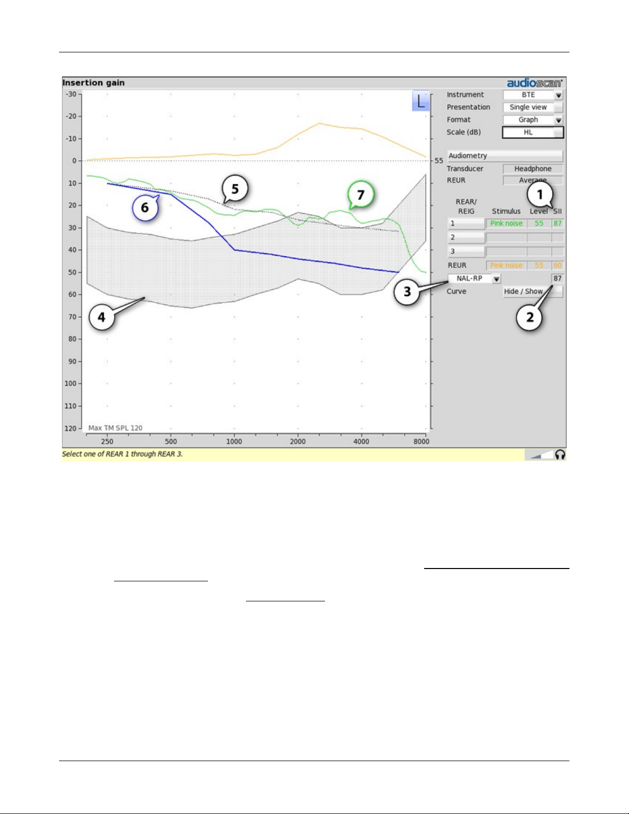
Verifit®User's Guide Version 4.2 © June 2015
1. Speech Intelligibility Index (SII), 2. SII for target Aided Threshold, 3. Fitting method, 4. Speech Region (@70 dB
SPL), 5. Target Aided Threshold, 6. Unaided Threshold, 7. Estimated Aided Threshold.
Audiometric data entry
Threshold data and parameters may be entered by scanning a barcode on a previous Audioscan printout or
manually using a mouse, or the numeric keypad on an external keyboard. See Mouse, keyboard, barcode scanner
and Input device operation.
To enter data from a barcode see Barcode data input and:
1. Press the barcode trigger and center the red line on the barcode from a distance of 6 – 8 in. (15 – 20 cm). The
scanner will beep and the Barcode entry poster opens.
2. Click [Done] to accept the data indicated on the poster.
To enter assessment data and parameters manually:
1. Select [Audiometry].
86

Verifit®User's Guide Version 4.2 © June 2015
2. Select [Transducer], then choose from the list.
3. Click [REUR] to toggle selection.
Measured REUR should be used with a soundfield threshold because individual REUR is part of the threshold.
Average REUR should be used with headphone or insert phone thresholds because individual REUR isn’t part of
these thresholds.
4. When all selections have been completed, press .
5. Enter HL threshold values using a mouse. Left click the mouse on the audiogram form to enter a point. Click
again to delete the point.
6. Press when all points have been entered.
The HL for the highest frequency is used for aided targets at higher frequencies.
REUR measurement procedure
Performing a REUR test erases all existing REAR and REIG data associated with the current test ear. REUR
should be measured only if Transducer = Soundfield. Otherwise it is more accurate to use average. See
Audiometric data entry.
1. Click the right mouse button and then select [Insertion gain]
2. Referring to On-Ear Measures - Setup and On-Ear Measures Screen Setup, prepare the system, position the
patient and insert the probe tube.
3. If REUR is set to Average, select [Audiometry] then click [REUR] to toggle to [Measure]. Press to
advance to the Threshold entry poster. You may enter threshold data at this time (see Audiometric data
entry) or press to proceed with the measurement.
4. Click REUR (below REAR/REIG test 3).
5. Press to accept the default 55 dB SPL Pink noise stimulus and capture the REUR curve OR select
[Stimulus] and [Level] to select other values. These choices have no impact on the resulting REIG.
6. If there is a notch in the 4000 to 8000 Hz region, try advancing the probe tube 2 mm and repeating step 3. If
the notch moves to a higher frequency, repeat this step until the notch moves beyond the highest frequency
of interest.
Because it is analyzed in 1/3 octave bands, the Noise stimulus produces a REUR 12 dB below that produced by
the Swept stimulus at the same overall level.
87

Verifit®User's Guide Version 4.2 © June 2015
The Average REUR used is shown above. Measured REUR will vary from this.
For small children the peak may shift to the right and become sharper. Drainage tubes and perforated ear drums
will cause large differences - usually around 1 kHz.
REAR measurement procedure
1. Click the right mouse button and then select [Insertion gain]
2. Referring to On-Ear Measures - Setup and On-Ear Measures Screen Setup, prepare the system, position the
patient and insert the probe tube. (For tight-fitting hearing aids or earmolds, the probe tube may be inserted
through a vent.)
3. Without disturbing the probe tube, insert the hearing instrument or earmold.
4. Referring to Audiometric data entry, enter threshold data.
5. Click button 1, 2, or 3 in the REAR/REIG column. This will present a signal from the sound-field speaker
and display the REAR Setup box.
6. Click [Stimulus], then select [Pink noise] or [Swept]. Use pink noise when using the NAL-NL1 fitting
formula. Use Swept when testing maximum output capabilities.
7. Click [Level], then select a stimulus level from the list box. Use the level shown on the target REIG curves
(if present). If no level is shown, use the lowest level required to overcome background noise.
8. Adjust the hearing instrument so that the REIG curve (SPL scale) or Aided threshold curve (HL scale)
approximates the dotted target curve. For multi-level targets, match each curve using the stimulus level
indicated.
9. Press to complete the test and capture the data.
See Insertion gain in SPL and Insertion gain in HL for an explanation of screen curves. See SII calculation in
Insertion gain
NOTE: Because it is analyzed in 1/3 octave bands, the Noise stimulus produces a REAR up to 12 dB below that
produced by the Swept stimulus at the same overall level. The REIGs will be similar except at levels which
cause non-linear operation of the hearing instrument.
SII calculation in Insertion gain
The Verifit calculates a Speech Intelligibility Index (SII) value for unaided speech at 70 dB SPL (REUR), the
target REIG and for each aided test. The calculations use the 1/3 octave band method of ANSI S3.5 –1997
without the 160 Hz band and without masking effects with results expressed as a % by multiplying by 100.
Level distortion effects are included but no hearing loss desensitization is applied. An idealized speech region of
LTASS +/- 15 dB is used.
88

Verifit®User's Guide Version 4.2 © June 2015
the listener. There is considerable individual variability in relating the SII to speech recognition, especially
amongst impaired listeners. The following shows expected nominal recognition scores vs SII for normals when
using a variety of speech stimulus conditions. (Killion and Mueller, Hearing Journal, January, 2010 pp 10-15).
CROS fitting using Insertion gain
See Insertion gain in SPL.
1. Place a probe module on each ear and insert the probe tube into the good ear only. Position the CROS
instruments on (in) the ears and turn them ON.
2. Position the speaker at 45 degrees to the good ear and set Instrument to [BTE].
3. Select REAR 1 and record a response using [Pink noise] at 55. It should be like a normal REUR. If not, the
ear may not be fully open.
4. Position the speaker at 45 degrees to the poor ear.
5. Set Instrument to [CROS].
6. Select REAR 2 and obtain a response using [Pink noise] at 55. Adjust the response to match that obtained in
step 3.
7. Position the speaker directly in front of the client. Select REAR 3 and use [Pink noise] at 55 to check for a
smooth response. Repeat with Instrument set to [BTE]. An irregular response may be the result of reflections
from nearby objects (including the operator) or it may indicate phasing problems in the aids.
89

Verifit®User's Guide Version 4.2 © June 2015
90
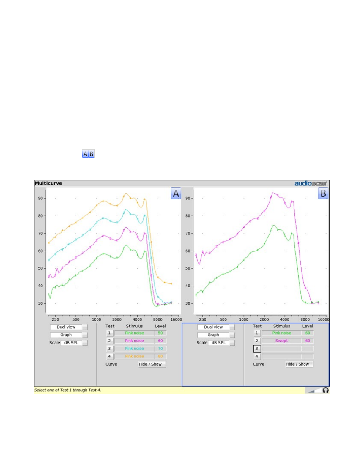
Verifit®User's Guide Version 4.2 © June 2015
15 Test Box Measures - Setup
The appearance of test box screens may be changed in several ways. Most screens may be viewed as a single,
full-screen or dual, side by side panels. Most screens may be formatted to show results in graphical or tabular
format. The Multicurve screen may be scaled in dB SPL or dB Gain. Individual curves may be hidden (but not
erased).
Test box screen
Except for Input/Output, Battery drain and Manual control screens, you have the option of selecting either a
single, full-screen view or a dual, side by side view. Some data may be dropped from the dual view.
To change the presentation, click [Single view] or [Dual view].
To switch between A and B test panel in single or dual view, right-click the mouse to raise the home menu and
click
In dual view, you may switch panels by left-clicking the mouse on a screen button in the inactive test panel.
However, this also operates the button.
91
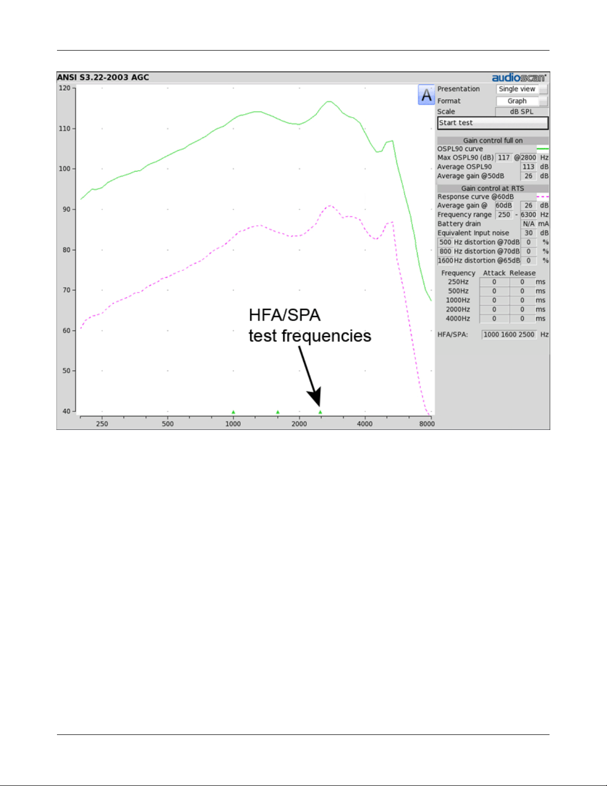
Verifit®User's Guide Version 4.2 © June 2015
92

Verifit®User's Guide Version 4.2 © June 2015
Format
Except for Distortion, Input/Output and Manual control screens, you have the option of selecting either a
graphic or tabular format.
To change the data format, click [Graph] or [Table].
Scale
On the Multicurve test screen, you have the option of displaying test results in SPL (dB) or gain (dB).
To change the scale, click [dB SPL] or [dB Gain]
Hide or Show test box curves
To hide or show unaided and aided curves on the Speechmap screen:
1. Click on the Hide/Show buttons located beside the Play button and test identifier numbers. Note that the
Hide/Show aided button has 3 states – Curves hidden, display LTASS only and display LTASS + speech
envelope (i.e. the 'speech banana').
93

Verifit®User's Guide Version 4.2 © June 2015
Hiding a curve does not erase it. To erase curves click and select one of the Erase data options.
To hide or show test curve(s) in all other applications:
1. Left-click [Hide/Show].
2. Click on the desired test result to toggle between the Hide or Show options. The curves will toggle on or off
when selected.
3. Click within the Curve Display poster to return to the test screen.
Hiding a curve does not erase it. To erase curves click on and select one of the Erase data options.
ANSI test frequencies
Automated tests of linear and AGC hearing aids may be conducted according to the ANSI S3.22-2003 test
standards. See ANSI S3.22-2003 facts
The Frequencies feature allows hearing instruments to be evaluated at the Special Purpose Average (SPA)
frequencies defined by ANSI S3.22, rather than the default High Frequency Average (HFA) frequencies. The
choice of SPA (or HFA) frequencies influences the average OSPL90, average full-on gain, reference test gain,
bandwidth and equivalent input noise. The frequencies at which distortion is measured are one-half the selected
SPA frequencies. You can also select the frequencies at which attack and release times are measured.
To change the averaging frequencies:
1. Right-click, choose and then click [ANSI].
2. Select the desired HFA/SPA test frequencies.
To change the frequencies for attack and release time measurements:
In the list of available frequencies, click on the frequencies to be used to measure attack and release time.
94

Verifit®User's Guide Version 4.2 © June 2015
Click on to save your selections.
Test box calibration facts
Test box microphone calibration establishes a correction curve for each uncalibrated test box reference
microphone by comparison with the factory calibrated coupler microphone. It may be performed as often as
desired but will be invalidated at 12 am the following day or at 12 am the following Monday, depending on the
choice of Daily or Weekly calibration interval. After the calibration has expired, the message window will turn
blue and you will be prompted to calibrate whenever you attempt a test that uses the test box microphones.
Your calibration curve should be similar to the one shown but may be at a different level. It should remain stable
over time. Irregularities in the calibration curve may be the result of not properly aligning the microphones. See
Calibrating test box reference microphone.
Calibrating test box reference microphone
Remove any coupler from the coupler microphone before calibration.
1. Position the test box reference microphones with their openings concentric with the binaural coupler
microphone openings and about 1 – 2 mm from as shown below.
2. Close and seal the test chamber.
3. Right-click the mouse and click [Calibration] under Test box.
4. Click [Daily] or [Weekly] to select the calibration interval.
5. Click [Calibrate] for each side. See Test box calibration facts
It is recommended that you print a copy of the initial calibration curve and compare it with your daily or weekly
95

Verifit®User's Guide Version 4.2 © June 2015
curve. Any change in this curve indicates a drift in either the coupler or the reference microphone which needs
further investigation. See Calibration check for coupler microphone for an additional check.
Calibration check for coupler microphone
Accuracy of test box measurements depends on the calibration of the coupler microphone. This should be
checked regularly using a microphone calibrator with an adapter ring. The RE780 (1 1/8 in.) and RE781 (1in.)
rings are designed for Quest CA22 and QC-10/20 respectively. To verify the coupler microphone calibration:
1. Calibrate the test box reference microphone. See Calibrating test box reference microphone
2. Screw the appropriate calibrator ring onto the coupler microphone.
3. Insert the coupler microphone with the attached calibrator ring into the calibrator opening.
4. Turn the calibrator on and adjust it to present one of the available frequencies and levels (e.g., 94 dB SPL at
1000 Hz).
5. Right-click the mouse and click [Manual control] under Test box.
6. Click the [Level] window, then select 0 from the drop-down list.
7. Click the [Frequency] window, then select the frequency of the calibrator (e.g. 1000 Hz) from the drop-down
list.
8. Click the [Filter] window, then select 1/12th octave from the drop-down list.
9. Click [Start test] (which changes to [Stop test]).
10.Check that the Coupler microphone level is within 1 dB of the calibrator level setting, +/- the calibrator
accuracy. For a 94 dB calibrator with +/- 0.3 dB accuracy, the indicated coupler microphone level should be
94 +/- 1.3 dB.
11.To stop the measurement, click [Stop test].
Coupling for binaural/wideband tests
For non-ANSI test-box tests (e.g. Test box Speechmap) the two 0.4 cc wideband couplers must be used. The
binaural coupler microphone is coded with a red and blue side for right and left ear respectively.
96

Verifit®User's Guide Version 4.2 © June 2015
When connecting the couplers onto the binaural coupler microphone, it is important that they produce a good
acoustic seal. Ensure each coupler is fully inserted in the retention slot. To remove, push the red or blue levers
while pulling up on the coupler.
BTE instruments are coupled to the 0.4cc coupler using the earmold and putty or using the provided earmold
substitues (HA-4) coupled to TRIC adapters. When the earmold is used, ensure the eartip is flush with the inside
of the coupler opening. Putty should not extend into the coupler cavity or block the sound outlet of the mold.
Vents should be sealed at the lateral end. It is very important that the instrument be well-sealed to the coupler.
Use the hearing instrument stabilizers to prop the BTE body in the vertical, as-worn position.
Custom instruments are sealed to the 0.4cc coupler with putty so that the end of the eartip is flush with the
inside of the coupler opening. Putty should not extend into the coupler cavity or block the sound outlet of the
instrument. Vents should be sealed at the faceplate end. It is very important that the instrument be well-sealed to
the coupler.
Open fit instruments may not be fit in the test-box.
RITE (Receiver in the ear) instruments which are fit with an occluded canal (e.g. with a micro-mold or
occluding dome) are coupled to the 0.4cc coupler using the TRIC adapter. For particularly large receivers,
insertion is easiest with the TRIC adapter not yet mounted on the coupler. Fold the TRIC adapter in half to open
the hole temporarily to ease insertion of larger receivers.
Excess low frequency output is usually due to open vents or a poor seal to the coupler.
For health reasons, hearing instruments should be clean before putty is applied and putty should be replaced
frequently.
Positioning HI for binaural/wideband tests
1. The hearing instrument should be coupled to the 0.4cc coupler with a battery installed. See Coupling the
hearing instrument for binaural/wideband tests
2. Place the binaural coupler microphone in the center of the test chamber so that the magnetic positioning aids
hold it directly over the crossbar.
3. Connect the instrument and coupler to the coupler microphone on the appropriate side so that the
microphone opening(s) of the instrument are facing forward, toward the main test box speaker.
4. Rotate the coupler and instrument so the angle approximates that of the instrument as worn on the client's
ear.
5. Position the test box reference microphone on the appropriate side as close as possible to the (front-facing)
97

Verifit®User's Guide Version 4.2 © June 2015
microphone opening of the hearing instrument without touching it. Ensure the reference microphones are
positioned within the safe zone, as indicated by the lighter colored test box foam.
Coupling for ANSI tests
The Verifit is supplied with two blue-colored, metal, 2cc couplers, a type HA-1 (ITE) and a type HA-2 (BTE)
for ANSI test box tests, and two silver-colored 0.4 cc wide-band couplers for all other test-box tests. Note that
an ANSI standard coupler for CICs does not exist; these must be tested in the HA-1 coupler.
When connecting the couplers onto the binaural coupler microphone, it is important that they produce a good
acoustic seal. Ensure each coupler is fully inserted in the retention slot. To remove, push the red or blue levers
while pulling up on the coupler.
For all ANSI tests, the instruments are coupled to the blue (left) side of the binaural coupler microphone.
BTE instruments are coupled to the HA-2 coupler by means of a 9 mm length of black Viton tubing. The only
purpose of this tubing is to seal the tip of the earhook to the coupler inlet. All of the tubing required by ANSI
S3.22 is machined into the metal stem of the HA-2 coupler. The tubing should be inspected regularly for cracks
or stretching which will cause feedback.
Custom instruments are sealed to the HA-1 coupler with putty so that the end of the eartip is flush with the
inside of the coupler opening. Putty should not extend into the coupler cavity or block the sound outlet of the
instrument. Vents should be sealed at the faceplate end. It is very important that the instrument be well-sealed to
the coupler.
Open fit instruments must use the coupler and coupling system specified by the manufacturer. This may involve
a hook that replaces the open fit tubing or an adapter tube that may be sealed to the opening of the HA-1 coupler
with putty or by using the TRIC adapter where appropriate.
RITE (Receiver in the ear) instruments are coupled to the HA-1 coupler using the TRIC adapter, except where
otherwise required by the hearing instrument manufacturer.
Excess low frequency output is usually due to open vents or a poor seal to the coupler.
98

Verifit®User's Guide Version 4.2 © June 2015
For health reasons, hearing instruments should be clean before putty is applied and putty should be replaced
frequently.
Positioning HI for ANSI tests
1. The hearing instrument should be coupled to the appropriate blue coupler and a battery pill or battery
installed. See Coupling the hearing instrument for ANSI tests.
2. Place the instrument and coupler in the test chamber so that the microphone opening(s) of the instrument are
on the crossbar within the test zone.
3. For directional instruments, the direction of maximum sensitivity should be oriented toward the speaker.
4. Position the test box reference microphone as close as possible to the (front-facing) microphone opening of
the hearing instrument without touching it.
5. Close and seal the test chamber.
Positioning a BTE instrument for ANSI tests
Positioning an ITE instrument for ANSI tests
99

Verifit®User's Guide Version 4.2 © June 2015
Positioning a RIC instrument for ANSI tests
100
 Loading...