

Audionet PRE I G3 User Manual

audionet
PRE1 G3
Stereo Pre-Amplifier
User's Manual
1

2

Contents
1 Preface ....................................................................... 5
1.1 Included ....................................................................................... 6
1.2 Transport..................................................................................... 6
2 Overview front panel ................................................ 7
3 Overview back panel ................................................ 8
4 Installation and power supply ................................. 9
4.1 Placement .................................................................................... 9
4.2 Mains connection ........................................................................ 9
4.3 Orientation of mains plug ........................................................ 10
4.4 Additional earth connection .................................................... 10
5 Inputs and outputs.................................................. 11
5.1 Inputs ......................................................................................... 11
5.2 Outputs ...................................................................................... 11
5.3 Recording devices ..................................................................... 12
5.4 Monitor ...................................................................................... 12
5.5 Phono ......................................................................................... 12
5.6 Audionet Link ........................................................................... 13
5.7 External power supply EPS or EPX ....................................... 13
5.8 Trigger output ........................................................................... 14
6 Usage ....................................................................... 15
6.1 Powering up .............................................................................. 15
6.2 Switching on and off ................................................................. 15
6.3 Mains phase detection .............................................................. 16
6.4 Using Audionet Link ................................................................ 16
6.5 Control elements on the front panel ....................................... 17
6.6 Volume control.......................................................................... 17
6.7 Display ....................................................................................... 18
6.8 Input selection ........................................................................... 19
6.9 Muting ....................................................................................... 20
7 Setup menu ............................................................. 21
3

7.1 Set Monitor ............................................................................... 22
7.2 Set Headphones ......................................................................... 23
7.3 Set Dim Level ............................................................................ 24
7.4 Balance Adjust .......................................................................... 25
7.5 Offset Adjust ............................................................................. 26
7.6 Set DC Servo ............................................................................. 27
7.7 Channel name ........................................................................... 28
7.8 Set Out 2 (Sub) .......................................................................... 29
7.9 Set Autostart ............................................................................. 30
7.10 Set Channel for By-Pass Mode ....................................................... 30
7.11 Set DC Servo for By-Pass M. ................................................... 33
7.12 Overview factory defaults ........................................................ 34
8 Audionet Metal Remote Control ............................ 35
8.1 Key assignment PRE1 G3 ........................................................ 36
8.2 Changing the batteries ............................................................. 36
8.3 Settings for Audionet preamplifier ......................................... 37
9 Technical information ............................................ 39
9.1 Design ........................................................................................ 39
9.2 Power supply ............................................................................. 39
9.3 Circuitry .................................................................................... 39
9.4 Handling .................................................................................... 39
10 Security advice ....................................................... 40
11 Technical data ........................................................ 41
4

1 Preface
The Audionet Team congratulates you on your purchase of this unit.
But before you start listening to your new Audionet PRE1 G3, please
read this manual carefully so you are able to use and enjoy all functions
of this unit without drawback on music quality.
5

1.1 Included
Included you will find the following items:
· the stereo pre-amplifier PRE1 G3
· the user's manual (that you are currently reading)
· one standard mains cord
· one green-yellow cord for an additional earth connection
· Audionet Metal Remote Control RC 1
1.2 Transport
Important
· Please transport the PRE1 G3 only in the included package.
· Always use the provided bag to prevent scratches on the casing.
· Please allow the PRE1 G3 to adapt to the climatic conditions in your
listening room before you switch on the unit for the first time after
transport.
6
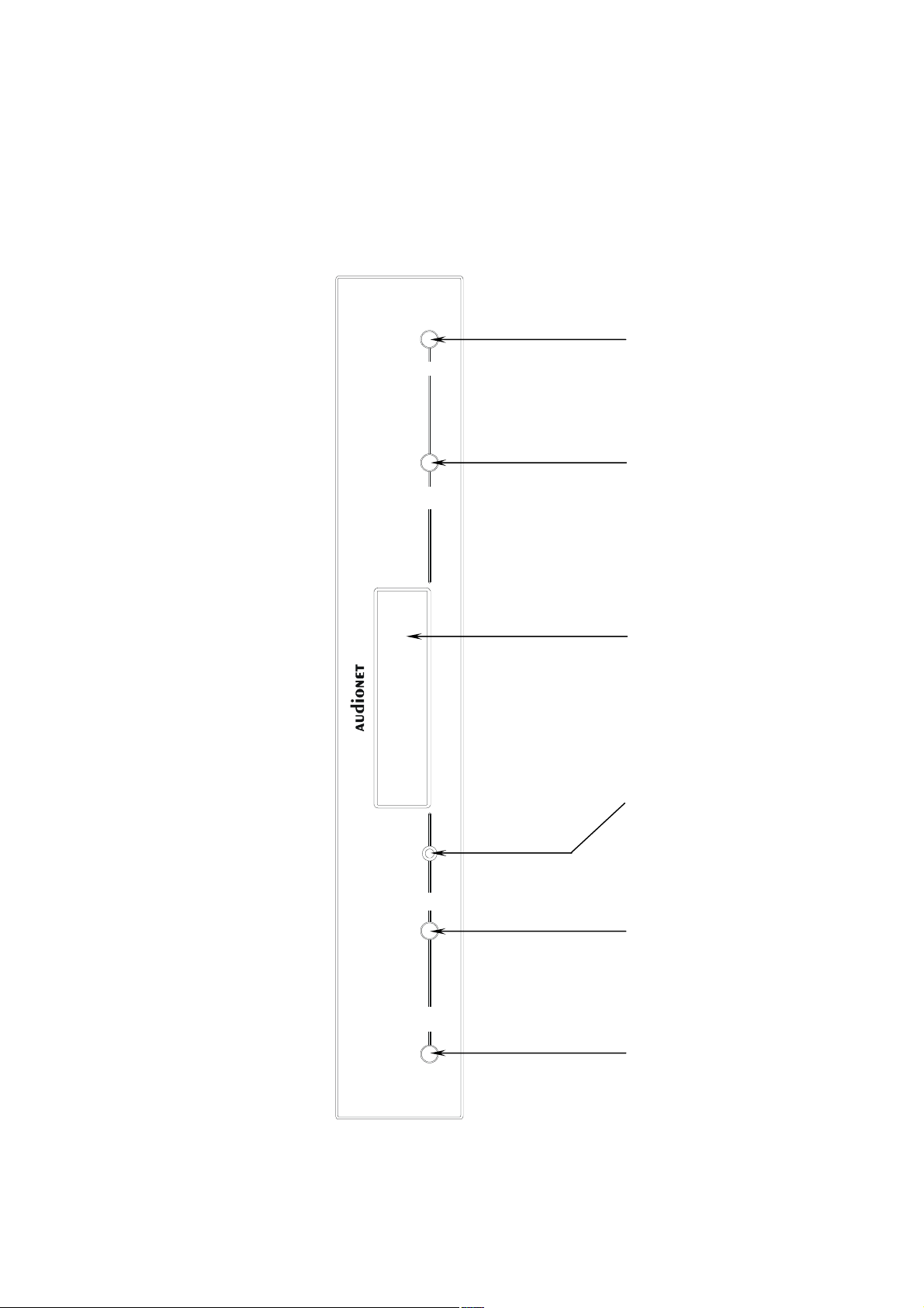
2 Overview front panel
power
down
up
set down power up
set
PRE 1 G3
key
key
Display
Stereo Preamplifier
IR remote
control receiver
key
key
7
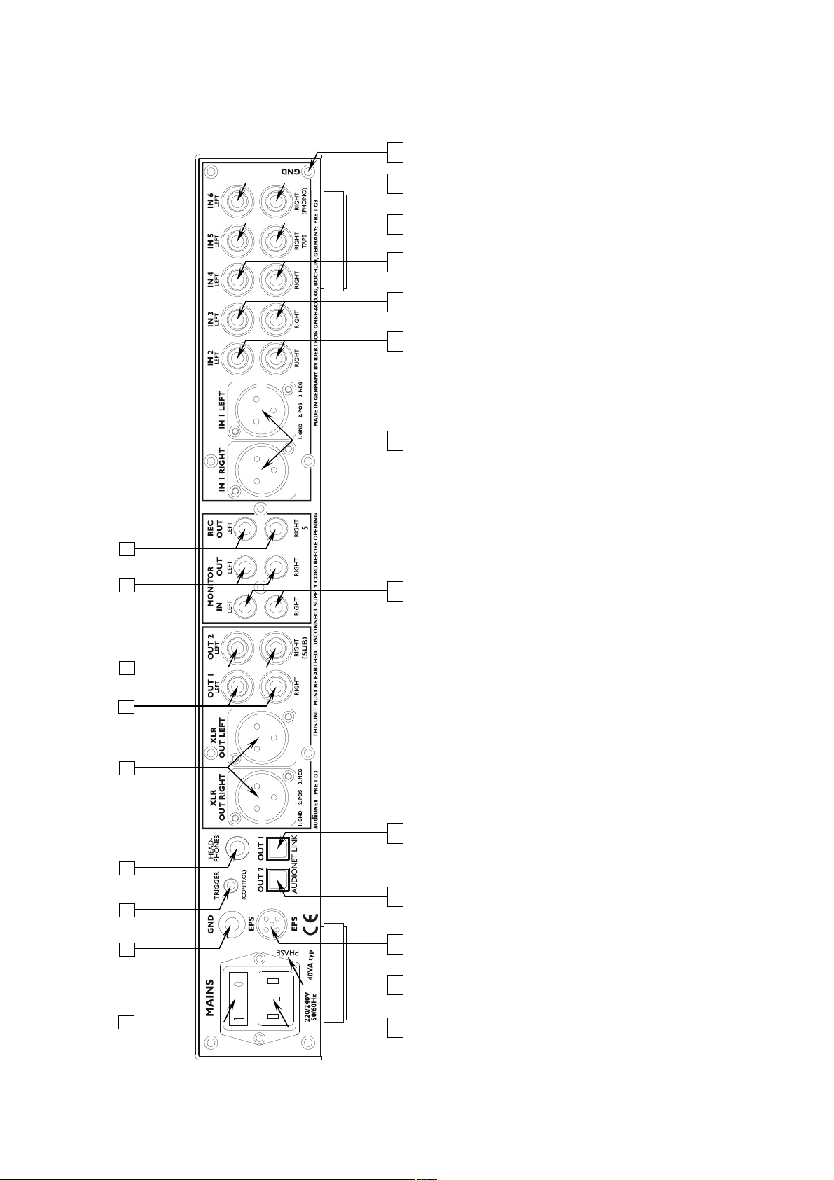
3 Overview back panel
1
7
8
10
16
17
19
20
21
10
11
12
13
OUT 1
OUT 2
14
15
Monitor input, left/right 18 Audionet Link output
Balanced (XLR) input no. 1, left/right
16
Audionet Link output
Marking mains phase 22 Mains input
5-pin connector for external power supply EPS
9 8
, left/right
17
REC OUT
7
6
Monitor output, left/right 9 Recording output
Earth connector for turn table (phono) 11 Cinch input no. 6, left/right 12 Cinch input no. 5, left/right 13 Cinch input no. 4, left/right 14 Cinch input no. 3, left/right 15 Cinch input no. 2, left/right
5
18
4
3
19
, left/right
, left/right
OUT 1
2
1
20
21
22
Mains switch 2 Additional earth connector 3 Trigger output (12 Volt) 4 Headphones output 5 Balanced (XLR) output, left/right 6 Cinch output
OUT 2
or Subwoofer (2x Mono)
Cinch output
8

4 Installation and power supply
Important
· During connecting and removing of sources or amplifiers to the
PRE1 G3 all units of your audio system have to be switched off to
prevent damage of the PRE1 G3 or any of the other connected units.
· Please make sure that all cables are in absolute best conditions!
Broken shields or short-cut cables could damage the PRE1 G3
and/or any other connected unit.
4.1 Placement
Important
· It is recommended to place the PRE1 G3 into a high quality rack or
onto a stable table.
· Do not expose the unit to direct sunlight.
· Do not cover the ventilation slots.
· Do not place the PRE1 G3 in close range to heat sources like radiators.
· Do not place the PRE1 on top of other units, especially not on top of
power amplifiers, pre amplifiers or similar that produce heat. Both
units could suffer damage from thermal overload.
· Do not use the unit in places where it is exposed to vibrations.
· Do not place the unit close to loudspeakers or into the corner of a
room where it is exposed to high levels of sonic energy, which might
reduce the sound quality of the unit.
4.2 Mains connection
The mains input 21 * is on the back panel of the PRE1 G3. To connect the
unit to mains use the included mains cord. If you prefer to use a different
power cord make sure that it meets the specifications for your home country.
Important
· The electrical specifications of your home country must meet the
electrical specifications printed onto the back panel.
*
see numbers in section 'Overview back panel' on page 8.
9

· The PRE1 G3 is a Class I unit and must be earthed. Please ensure a
stable earth connection. Phase ('hot' pin) is marked on the back panel
('phase') 21 .
· If you connect the mains cord please make sure that mains switch 1
at the back panel is switched off.
· Never pull the mains plug while the PRE1 G3 is switched on! Before
you pull the mains cord off its socket 22 at the back panel, power down
the unit to stand-by mode and switch off the unit using mains switch 1 .
Only in cases of extended absence – like vacations – or if massive trouble
on the mains power is to be expected you should switch off the PRE1 G3
from the mains using mains switch 1 . To disconnect the unit completely
from mains pull the mains plug.
Tip
· The use of high quality mains cords could improve sound quality.
Ask your local dealer for more information.
4.3 Orientation of mains plug
The correct polarization of mains is important for reasons of audio clarity
and stability. Please connect the mains cord so that the hot pin of the wall
outlet is connected to the pin of the mains input 22 marked 'phase' 21 .
Your Audionet PRE1 G3 is able to detect a wrong polarization of the
mains plug during start-up. If the message
Attention: Mains
Phase incorrect!
appears in the display, switch off the unit and flip the mains plug in the
wall outlet (see section 'Mains phase detection' on page 16).
4.4 Additional earth connection
Included with the PRE1 G3 you will find a green-yellow cord for the
additional earth connection. Attach this cord to the earth connector 2 on
the back panel of the PRE1 G3 and put the plug into the mains socket
right beside the mains cord of your PRE1 G3. This ensures an additional
and stable earth connection resulting in a better sound.
Note
· We strongly recommend using the additional earth connection!
· Also, a stable earth connection is necessary for the PRE1 G3 detect-
ing the polarization of mains phase correctly.
10

5 Inputs and outputs
Important
· During connecting and removing of sources or amplifiers to the
PRE1 G3 all units of your audio system have to be switched off to
prevent damage of the PRE1 G3 or any of the other connected
units.
· Please make sure that all cables are in absolute best conditions!
Broken shields or short-cut cables could damage the PRE1 G3
and/or any other connected unit.
5.1 Inputs
The PRE1 G3 is equipped with 5 Cinch inputs 11 to 15 and one balanced (XLR) input 16 for connecting signal sources at line level. Additionally, the monitor input 17 can used as another line level input.
Please connect the left and right input of the same number printed on the
back panel of the PRE1 G3 to the corresponding output of the source you
would like to connect to the PRE1 G3.
5.2 Outputs
The PRE1 G3 is equipped with two Cinch outputs OUT 1 6 and OUT 2
7 as well as one balanced (XLR) output XLR OUT LEFT and
XLR OUT RIGHT 5 for the left and right channel to connect the unit to
your amplifier(s).
Use the Cinch output OUT 1 6 to connect the PRE1 G3 to your power
amplifier(s) using high quality Cinch cables. Alternatively, you may connect the power amplifier using the balanced (XLR) outputs
XLR OUT LEFT and XLR OUT RIGHT 5 in case your power amplifier
does not support Cinch (line) inputs.
Note
· Of course you may use the Cinch output OUT 2 7 to connect the
unit to your amplifier(s). The menu item SET SUB OUT has to be set
to Left & Right, otherwise the Cinch output OUT 2 7 works as a
Subwoofer output (see section 'Set Out' on page 29).
11

Tip
· The pinning of the balanced (XLR) input 16 and output 5 is
printed right beside the connectors.
5.3 Recording devices
You can connect up to two recording devices or effect processors to the
PRE1 G3 for recording and playback.
Connect the recording devices (like DAT or tape recorder) to the recording output REC OUT 9 of the PRE1 G3. For playback please connect your recording devices only to input no. 5 IN 5 12 of the PRE1 G3.
if they are also connected to the output REC OUT 9 of your PRE1 G3.
If you select input no. 5 IN 5 12 the output REC OUT 9 is switched off
to prevent any feedback loops between your recording device and the
PRE1 G3.
Please use inputs no. 1 16 to no. 4 13 and no. 6 11 to connect sources
you like to record from. With these inputs the recording output REC OUT
9 is always active
5.4 Monitor
The monitor loop of the PRE1 G3 makes it possible to insert a recording
device (for read after write verify) or an effects processor (e.g. surround
decoders) into the signal path.
Connect monitor output MONITOR OUT 8 of the PRE1 G3 to the input of the unit you would like to insert. Also, connect the output of the
unit to the monitor input MONITOR IN 17 of the PRE1 G3.
For further information on how to use the monitor loop please refer to
section 'Set Monitor' on page 22.
5.5 Phono
The PRE1 G3 can be upgraded with a phono pre amplifier. In this case
use input no. 6 IN 6 11 marked PHONO to connect your turn table to
the PRE1 G3. Connect the earth wire of your turn table to the earth connector GND 2 right beside input no. 6. For further information on the
optional phono module please refer to its user's manual.
12

Important
· If the PRE1 G3 is upgraded with the optional phono module, input
no. 6 IN 6 11 must only be used to connect a turn table.
5.6 Audionet Link
For your convenience, the PRE1 G3 can switch on/off all other Audionet
units (e.g. power amplifiers) connected via 'Audionet Link' by a simple
touch on the remote control or the power key on the front panel.
You only need a simple optical 'Toslink' cable. Connect the 'Audionet
Link' output OUT 1 18 or OUT 2 19 of your PRE1 G3 to the 'Audionet Link' input of unit to be controlled.
The PRE1 G3 is equipped with two 'Audionet Link' outputs OUT 1 18
and OUT 2 19 . 'Audionet Link' output 1 OUT 1 18 is always on
while the PRE1 G3 is switched on. However, 'Audionet Link' output
OUT 2 19 is controlled depending on the settings for the headphones
output. Please refer to section 'Set Headphones' on page 23.
Therefore, use 'Audionet Link' output OUT 2 19 in order to connect
power amplifiers to the PRE1 G3 via 'Audionet Link'. Connect units you
would like to control independently from the headphones settings (e.g.
tuner, CD player etc) to 'Audionet Link' output OUT 1 18 .
Tip
· Audionet source units and power amplifiers are usually equipped not
only with an 'Audionet Link' input, but additionally with an 'Audionet
Link' output to connect further Audionet devices to be controlled via
'Audionet Link' in a daisy chain. Connect this 'Audionet Link' output
to the 'Audionet Link' input of the next Audionet unit using a simple
optical 'Toslink' cable allowing you to switch on/off your complete
Audionet system by your Audionet pre amplifier.
5.7 External power supply EPS or EPX
In order to use one of the optional external precision power supplies
Audionet EPS or Audionet EPX with you PRE1 G3 please proceed as
follows:
1. Make sure both PRE1 G3 and EPS / EPX are switched off and
disconnected from mains.
2. Connect the EPS / EPX with the included cable to input jack EPS
20 on the back panel of the PRE1 G3. The shape of the plug
prevents any wrong polarity. The small 'nose' inside the plug has
13
 Loading...