

Audionet PRE-G-2 Owners manual

Reference Pre-Amplifier
User's Manual
1

2

Contents
1 Preface......................................................................5
1.1 Included.......................................................................................6
1.2 Transport.....................................................................................6
2 Overview front panel................................................7
3 Overview back panel................................................8
4 Installation and power supply.................................9
4.1 Placement....................................................................................9
4.2 Mains connection........................................................................9
4.3 Orientation of mains plug........................................................10
4.4 Additional earth connection....................................................10
5 Inputs and outputs.................................................11
5.1 Inputs.........................................................................................11
5.2 Outputs......................................................................................11
5.3 Recording devices.....................................................................12
5.4 Audionet Link...........................................................................12
6 Usage.......................................................................13
6.1 Powering up..............................................................................13
6.2 Switching on and off.................................................................13
6.3 Mains phase detection..............................................................14
6.4 Using Audionet Link................................................................14
6.5 Control elements on the front panel.......................................15
6.6 Volume control..........................................................................15
6.7 Display.......................................................................................16
6.8 Input selection...........................................................................17
6.9 Muting.......................................................................................17
7 Setup Menu.............................................................18
7.1 Set Dim Level............................................................................19
7.2 Balance Adjust..........................................................................20
7.3 Offset Adjust.............................................................................21
7.4 Set DC Servo.............................................................................22
3

7.5 Channel name...........................................................................23
7.6 Set Autostart.............................................................................23
7.7 Set Off-Text...............................................................................24
7.8 Set Channel for By-Pass Mode................................................25
7.9 Overview factory defaults........................................................25
8 Remote control........................................................26
8.1 Screen page 1.............................................................................27
8.2 Screen page 2.............................................................................28
9 Special function By-Pass Mode.............................29
10 Technical information.............................................32
10.1 Design.........................................................................................32
10.2 Power supply.............................................................................32
10.3 Circuitry....................................................................................32
10.4 Handling....................................................................................32
10.5 Update PRE to PRE G2...........................................................33
11 Security advice........................................................34
12 Technical data.........................................................35
4

1 Preface
The Audionet Team congratulates you on your purchase of this unit.
Music lovers know about the importance of the pre amplifier: The pre
amplifier determines the sound quality. For those enthusiast we developed the PRE G2, our pre amplifier reference.
The PRE G2 is a luxurious source of pure sound. With the highest accuracy and resolution, coarse and fine dynamic precision and overwhelming
spatiality it reproduces music in all its naturalness.
The PRE G2 does not accept compromise. With fundamental scientific
research and elaborate development and trial, each detail was conceived
and tested. The circuitry is state-of-the-art, its design beyond all doubt
and all its components painstakingly selected.
As nothing else could satisfy our demands, we produce operational amplifiers, incremental encoder and signal cables ourselves. Volume is controlled by an electronically switched and in real-time linearized resistor
network made of discrete high quality metal film resistors. The audio
signal path and control circuitry are decoupled optically. Input and output
circuits are immune to negative influences of connected devices. Thus,
the PRE G2 manifests the limits of what is possible nowadays regarding
measuring techniques. Noise, distortion and crosstalk are almost eliminated.
A microprocessor facilitates versatile control functionality and highest
handling comfort. All information is delivered through a big vacuum
fluorescent display. Every function is supported by the remote control.
Never show the PRE G2 to other pre amplifiers! The will go green with
envy.
But before you start listening to your new Audionet PRE G2, please read
this manual carefully so you are able to use and enjoy all functions of this
unit without drawback on music quality.
5

1.1 Included
Included you will find the following items:
· the reference pre amplifier PRE G2
· the Audionet System Remote Control SRC
· the user's manual (that you are currently reading)
· one Audionet power cord APC
· one green-yellow cord for an additional earth connection
1.2 Transport
Important
· Please transport the PRE G2 only in the included package.
· Always use the plastic bag to prevent scratches on the casing.
· Please allow the PRE G2 to adapt to the climatic conditions in your
listening room before you switch on the unit for the first time after
transport.
6

2 Overview front panel
power
mute
input
PRE G2
set mute power volume input
set
knob
volume
encoder)
(incremental
IR remote
control recevier
key
key
key
key
Stereo Preamplifier
Display
7
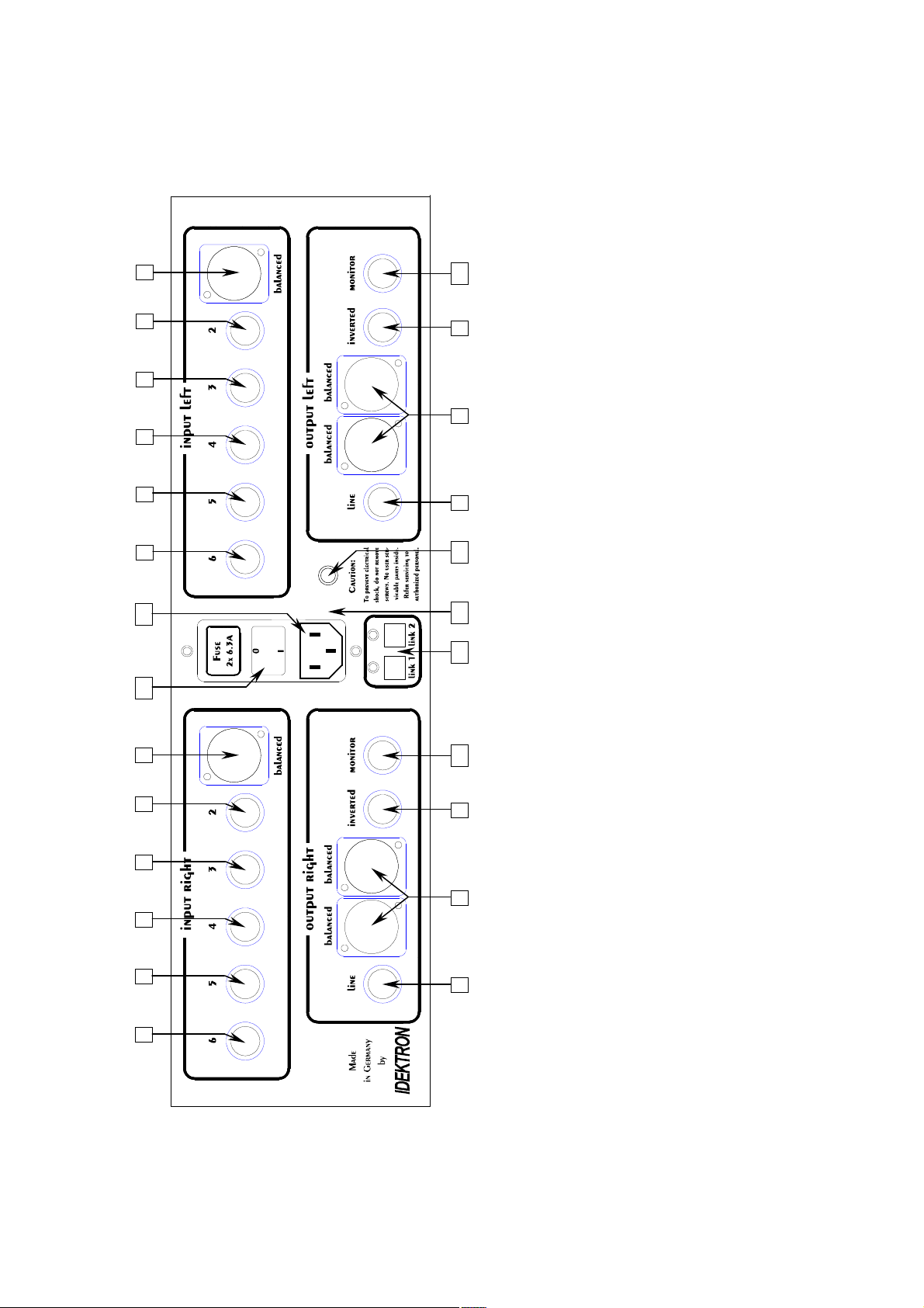
3 Overview back panel
AC: 220/240 V
phase
gnd
1
9
10
1
2
5
10
9 7
8
6 4 3
12
14
1
2
5
15
13
11
10
9 7
8
Monitor output, left/right 11 Outputs Audionet Link 1 and 2 12 Mains input 13 Marking mains phase 14 Mains switch 15 Additional earth connector
Inverted Cinch (line) output, left/right
Balanced (XLR) input no. 1, left/right 2 Cinch (line) input no. 2, left/right 3 Cinch (line) input no. 3, left/right 4 Cinch (line) input no. 4, left/right 5 Cinch (line) input no. 5, left/right 6 Cinch (line) input no. 6, left/right 7 Cinch (line) output, left/right 8 Balanced (XLR) outputs, left/right
6 4 3
50/60 Hz
8

4 Installation and power supply
Important
· During connecting and removing of sources or amplifiers to the
PRE G2 all units of your audio system have to be switched off to
prevent damage of the PRE G2 or any of the other connected
units.
· Please make sure that all cables are in absolute best conditions!
Broken shields or short-cut cables could damage the PRE G2
and/or any other connected unit.
4.1 Placement
Important
· It is recommended to place the PRE G2 into a high quality rack or
onto a stable table.
· Do not expose the unit to direct sunlight.
· Do not place the PRE G2 in close range to heat sources like radiators.
· Do not place the PRE G2 on top of other units, especially not on top
of power amplifiers, pre amplifiers or similar that produce heat. Both
units could suffer damage from thermal overload.
· Do not use the unit in places where it is exposed to vibrations.
· Do not place the unit close to loudspeakers or into the corner of a
room where it is exposed to high levels of sonic energy, which might
reduce the sound quality of the unit.
4.2 Mains connection
The mains input 12 * is on the back panel of the PRE G2. To connect the
unit to mains use the included mains cord. If you prefer to use a different
power cord make sure that it meets the specifications for your home
country.
*
see numbers in section 'Overview back panel' on page 8.
9

Important
· The electrical specifications of your home country must meet the
electrical specifications printed onto the back panel.
· The PRE G2 is a Class I unit and must be earthed. Please ensure a
stable earth connection. Phase ('hot' pin) is marked on the back panel
('phase') 13 .
· If you connect the mains cord please make sure that mains switch
14 at the back panel is switched off.
· Never pull the mains plug while the PRE G2 is switched on! Before
you pull the mains cord off its socket 12 at the back panel, power
down the unit to stand-by mode and switch off the unit using mains
switch 14 .
Only in cases of extended absence (like vacations) or if massive trouble
on the mains power is to be expected you should switch off the PRE G2
from the mains using mains switch 14 . To disconnect the unit completely from mains pull the mains plug.
4.3 Orientation of mains plug
The correct polarization of mains is important for reasons of audio clarity
and stability. Please connect the mains cord so that the hot pin of the wall
outlet is connected to the pin of the mains input 12 marked 'phase' 13 .
Your Audionet PRE G2 is able to detect a wrong polarization of the
mains plug during start-up. If the message
Attention: Mains
Phase incorrect!
appears in the display, switch off the unit and flip the mains plug in the
wall outlet (see section 'Mains phase detection' on page 14).
4.4 Additional earth connection
Included with the PRE G2 you will find a green-yellow cord for the additional earth connection. Attach this cord to the earth connector 15 on the
back panel of the PRE G2 and put the plug into the mains socket right
beside the mains cord of your PRE G2.
This ensures an additional and stable earth connection resulting in a better
sound.
Note
· We strongly recommend using the additional earth connection!
· Also, a stable earth connection is necessary for the PRE G2 detecting
the polarization of mains phase correctly.
10

5 Inputs and outputs
Important
· During connecting and removing of sources or amplifiers to the
PRE G2 all units of your audio system have to be switched off to
prevent damage of the PRE G2 or any of the other connected
units.
· Please make sure that all cables are in absolute best conditions!
Broken shields or short-cut cables could damage the PRE G2
and/or any other connected unit.
5.1 Inputs
The PRE G2 is equipped with one balanced (XLR) 1 and 5 Cinch (line)
inputs 2 to 6 for connecting signal sources at line level. Due to its
double mono design, left and right channel input jacks are separated on
the back panel.
Please connect the left and right input of the same number printed on the
back panel of the PRE G2 to the corresponding output of the source you
would like to connect to the PRE G2.
5.2 Outputs
The PRE G2 is equipped with a pair of balanced (XLR) 8 and a pair of
Cinch (line) outputs 7 and 9 for the left and right channel each to connect the unit to your amplifier(s). The Cinch (line) output 9 is inverted.
Due to the double mono design the left and right output jacks are separated.
Use the left and right Cinch (line) output 7 to connect the PRE G2 to
your power amplifier(s) using high quality Cinch cables. Alternatively,
you may connect the power amplifier using the balanced (XLR) outputs
8 in case your power amplifier does not support Cinch (line) inputs.
The inverted outputs 9 are primarily designated for amplifiers in
bridged operations (in combination with the Cinch (line) outputs 7 ).
Important
· Bridged operations of an amplifier demand a correct setup and connection. Please consult your dealer and/or the manufacturer of your
power amplifier to prevent damage to your equipment.
11
 Loading...