

Audionet MAP I User Manual

audionet
MAP I
Multi Channel Audio/Video Pre - Amplifier
User's Manual

2

Contents
CONTENTS ........................................................................................................ 3
PLACEMENT AND CONNECTION .................................................................... 4
ADDITIONAL EARTH CONNECTION ............................................................... 5
AUDIONET LINK ............................................................................................... 5
POLARISATION OF MAINS PLUG ................................................................... 5
CONNECTING THE EXTERNAL POWER SUPPLY EPS / EPX ....................... 5
OVERVIEW OF CONNECTIONS ....................................................................... 6
AUDIO/VIDEO-CONNECTIONS ........................................................................ 7
FIRST STEPS .................................................................................................... 9
USAGE FRONT PANEL .................................................................................. 11
OVERVIEW OF MENU STRUCTURE.............................................................. 12
AUDIONET SYSTEM REMOTE CONTROL .................................................... 13
SETUP ............................................................................................................. 25
DISPLAY .......................................................................................................... 37
ON SCREEN DISPLAY (OSD) ......................................................................... 41
PROGRESSIVE SCAN CARD ......................................................................... 42
OVERVIEW VIDEO OUTPUTS ........................................................................ 48
USB AUDIO ..................................................................................................... 49
SECURITY ADVICE ......................................................................................... 53
3

Placement and connection
Important:
· Warning! Please read this manual prior to operating the MAP 1 in order to
avoid damage on your valuable equipment.
Also, please make sure all units of your audio/video system are switched off while
connecting or disconnecting any cables to avoid damage of the input and/or output
sections of your units.
Please make sure that your Audionet MAP 1 is installed at a place that is sufficiently
ventilated to allow the heat to leave.
The mains input 17 *) is located at the back panel of the MAP 1. Please use the
provided power cord to connect the MAP 1 to mains. If you want to use a different
power cord make sure that it meets the specifications for your home country.
Important:
· The electrical specifications at the back must meet the specifications of your
home country.
· The mains switch at the back panel has to be switched off before connecting the
MAP 1 to mains. The MAP 1 is a Class I device and must be earthed. Please
ensure a stable earth connection. 'Phase'/'Hot pin' is marked at the back panel
(PHASE) 17 .
The MAP 1 is a stand by device. Please use the mains switch 17 at the back panel to
switch on the MAP 1. After a short time the display reads off or small dot to report
that the unit is in stand by mode now (see chapter 'Setup', section 'Global Setup', menu
item 'Set Stand By Text').
Only in case of extended absence (like vacations) or if massive trouble on mains power
is to be expected you should disconnect the unit from the mains. Switch off the MAP 1
with the mains switch at the back panel 17 . The display will go out.
Important:
· Before switching off the mains switch of the MAP 1, please make sure that all
units connected to the outputs of the MAP 1 are switched off, too.
· Long term usage of the display set to maximum brightness (setting 100%) may
cause extended signs of wear resulting in a decay of contrast or brightness of
individual dots in the display. Do not use the display with a brightness set higher
than the factory default setting of 50% over a longer period of time (refer to Chapter
'Audionet System Remote Control')!
*)
see numbers on page 'Overview of connections'
4

Additional earth connection
Optionally, there is a special cord available for an additional earth connection to be used
with earth connector 1 . Use the screw of earth connector 1 to connect the additional
ground cord to the MAP 1. Put the plug of the ground cord into a mains socket near your
power cord. The sound will be improved.
Tip:
· We strongly recommend using the additional earth connection!
Audionet Link
In connection with other Audionet devices like AMP I, AMP, MAX, AMP III, AMP IV,
AMP V, AMP VII etc. your MAP 1 is able to switch on/off the complete system. Please
connect a Toslink plastic fibre cable from the Audionet-Link Output 8 at the back of
the MAP 1 to the Audionet-Link inputs of other Audionet devices. For further
instructions please read the user's manual of the other Audionet devices.
Polarisation of mains plug
The correct polarizing of mains is important for reasons of audio clarity and stability.
Therefore the Audionet MAP 1 indicates a wrong polarisation of the mains lead. While
powering up, the MAP 1 checks the mains polarisation. If you read
► Attention: ◄
► Mains Phase incorrect ◄
switch off the MAP and then flip the plug in your wall outlet.
Connecting the external power supply EPS / EPX
Use the provided special cord to connect the optionally available EPS / EPX to the EPSInput 2 at the back panel of the MAP 1. Connect both (!!) units (MAP 1 and
EPS / EPX) with mains. Switch on first the MAP 1 then the EPS / EPX with the mains
switch at the back of the units. The MAP 1 is now in stand by mode. You can start up
the MAP 1 by pressing the power key at the front panel, or the key Power On or
Power Toggle on the remote control.
To disconnect both units from the mains please make sure first, that the MAP 1 is
switched off to stand by mode using the power key at the front panel or the key
Power Off or Power Toggle on the remote control. Now you can disconnect the
units from the mains by switching off first the MAP 1, then the EPS / EPX using the
mains switch at the back panel of the units.
5
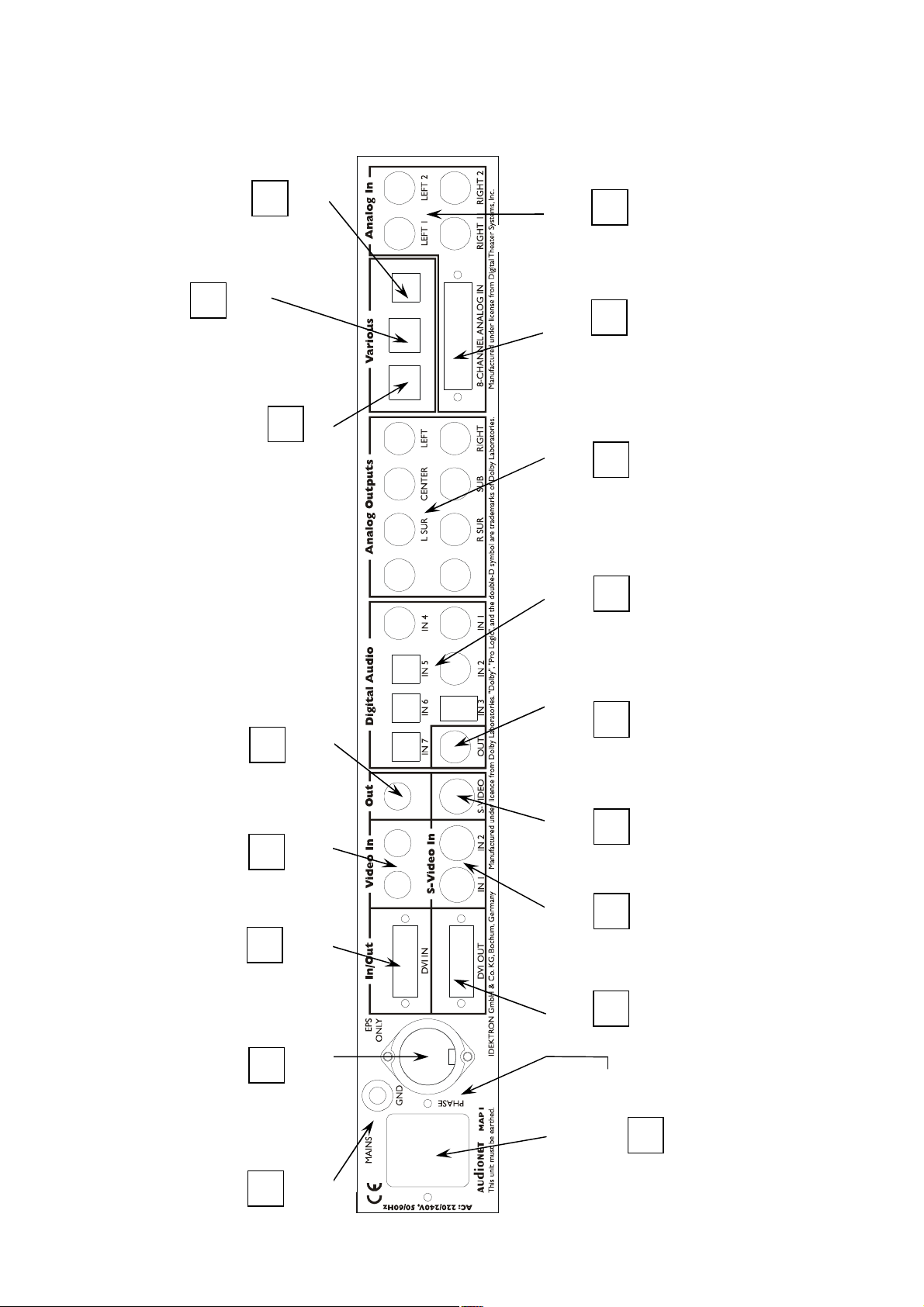
Overview of connections
LBACK RBACK
10 9 8 7 6 5 4 3 2 17 16 15 14 13 12 11
Additional earth
Connector for the external
DVI video
Digital inputs
USB data interface
Channel Analog
IN 1 IN 2 FBAS
(C
Digital input 8
Audionet Link
connector
inputs
2-
AUDIONET
LINK
USB-Audio
USB
USB
AUDIO
CONTROL
8-Channel
analog input
analog output
Multi-Channel
1 to 7
Digital output:
Digi Rec Select
Composite
video output
IN)
R
output
(Y)
Composite
video input
)
B
(C
S-Video
S-Video
inputs
input
output
DVI video
power supply EPS / EPX
1
Mains input and
mains power switch
Marking mains phase
connector
6

Audio/Video-Connections
Analog Inputs:
Connect 2-channel analog sources to one of the two analog inputs 9 (Analog In LEFT
1/ RIGHT 1 or Analog In LEFT 2/ RIGHT 2). Both analog inputs are setup to pure
analog 2-channel signal routing by default. If you have the 2-channel analog outputs of
your DVD-Player, LaserDisc-Player, VCR or any other analog source connected to the
MAP 1 and want to use Dolby* Pro Logic IIx or DTS** Neo:6 for decoding Surround
encoded stereo material, switch internal decoder mode to Multi-Channel for the
corresponding analog input 9 (see chapter 'Setup', section 'Decoder Setup').
If you have the optional phono card installed, plug in the MM- or MC pickup of your
turn table into input Analog In LEFT 2/ RIGHT 2 9 and connect the chassis of the
turn table to the ground screw GND 1 . The phono card offers independent selection of
gain, input capacity and input resistance for optimal adjustments to all kinds of available
pickup systems. For further details please refer to the enclosed user's manual of the
phono card.
Digital Inputs
Connect your digital sources to digital inputs 1 to 7 12 . By factory default digital
inputs 1,2,3 and 5 are setup for multi channel decoding (Dolby Digital and DTS).
Digital inputs 4,6,7 and 8 are setup for stereo PCM signals (all default setting can be
changed by the user in the setup menus!). Use digital input 8 7 to connect the MAP 1
to a Computer using USB Audio to playback sound and music files (refer to chapter
'USB Audio').
In order to send DVD-Audio music data across the HighBit interface from the DVD
player Audionet VIP1) to the MAP 1, connect digital output 1 of the VIP with digital
input Digital Audio IN 1 of the MAP 1. Furthermore, you need a second connection
running from digital output 2 of the VIP to digital input Digital Audio IN 2 of the
MAP 1. Only in case of both connections are setup and the switch for the interface
mode on the back panel of the VIP is set to h-bit (refer to owner's manual of VIP), it is
possible to receive and decode DVD-Audio data with the MAP 1.
Note:
· Data on the Audionet HighBit interface will be recognized and decoded
automatically by the MAP 1. If the second data connection is missing the MAP 1
will issue the error message: ► Check HighBit Cable 2 ◄.
Please check the correct setup and connection of both cables from VIP to MAP 1.
· Alternatively, you can use the digital input Digital Audio IN 3 of the
MAP 1. Connect the datalink output of the VIP by using a common 'Firewire' or
'IEEE1396' cable with the Digital Audio IN 3 of the MAP 1. In this case the switch
(Digital Audio)
:
1
Make sure your VIP supports the HighBit DVD-Audio interface. Software upgrades are available for older models.
7
for the interface mode on the back panel of the VIP has to be set to h-bit mode (refer
to owner's manual of VIP), to receive and decode DVD-Audio data with the MAP 1.
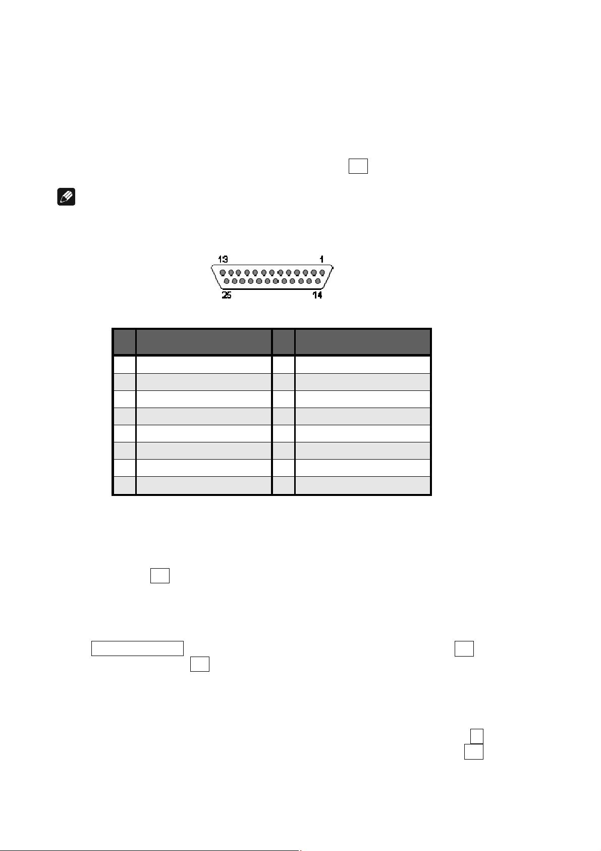
External 8-Channel Analog Inputs:
Plug in analog multi channel sources (external decoder, DVD-Player with internal
decoder, SACD-Player etc.) into the 8-channel analog input 10 of the MAP 1.
Note:
· The External 8-Channel Analog Input provides no signal processing at all, only pure
analog volume control!
Pin assignment External 8-Channel Analog Input
Pin
1 Front Left 14 Ground Front Left
2 Center 15 Ground Center
3 Front Right 16 Ground Front Right
4 Subwoofer 17 Ground Subwoofer
5 Left Surround 18 Ground Left Surround
6 Right Surround 19 Ground Right Surround
7 Left Back 20 Ground Left Back
8 Right Back 21 Ground Right Back
Signal Pin
Signal
Analog Outputs:
All analog outputs 11 are located in the section Analog Outputs in the right part of the
back panel.
Digital Outputs (Digital Audio Out):
Select DigiRec Select in the setup menu, which of the digital input 1 to 7 12 is
routed to the digital output 13 . The digital record select works independently, therefore
you can use digital out for recording while listening to a different source.
Video Inputs (Video In / S-Video In):
Plug in your cinch/composite video sources into video inputs IN 1 and IN 2 4 .
S-Video sources are to be connected to video inputs S-Video In 1 and S-Video In 2 15 .
Use the video inputs in any order as each of the 4 video inputs can be assigned to every
audio input (see menu 'Video Setup' and 'Channel Setup'). Even multiple assignments
8

are allowed, i.e. one and the same video input can be assigned to more than one audio
input.
Video Outputs:
The video signal assigned to the current audio input is available at the Video Out jacks;
cinch video at FBAS 5 and S-Video at S-VIDEO 14 . All video signals at the cinch
video inputs are converted to S-Video format by the internal 'Cinch Video to S-Video
Converter' and available at the output S-VIDEO. The On Screen Display (OSD) is
available at video outputs VIDEO 5 and S-VIDEO 14 .
Alternatively, both video inputs VIDEO IN1 and IN2 together with video output FBAS
can be re-defined as secondary component video (YUV) input (refer to chapter 'Setup'
section 'Set video input' and chapter 'Progressive Scan Card' for further details and
connection diagram).
DVI Video In-/Outputs:
The DVI video input and output sockets are both designed for analog and digital video
signals (DVI-I). If no progressive scan card is installed, the analog or digital input
signals of the DVI input socket are directly sent to the output socket (refer to chapter
'Setup' section 'Set video input' ).
Note:
· Digital DVI video signals are not processed by the installed progressive scan card
but only routed through from input 3 to output 16 , if the option
Set Video Input :
DVI-Int. In
is selected.
· Interlaced analog video formats, which are fed into a video 4 , S-Video 15 or DVI
analog input 3 can only be converted into a progressive digital DVI video format, if
the optional progressive scan card and the optional DVI Module are both installed.
· Please refer to chapter 'Progressive Scan Card' for detailed information about
connection and configuration of the optional Progressive Scan Card.
First Steps
The following provides a short overview of the first steps and their order to setup the
MAP 1. For any detailed description please refer to the sections 'Usage front panel' and
'Audionet System Remote Control'.
After connecting your MAP 1 to the other components of your Hifi or Home Cinema
system (refer to section 'Audio / Video connections'), some setup options have to be
configured. Your MAP 1 needs information about the number of speakers, their
9

distances from the listening position and sensitivity to work with optimum performance.
The setup procedure is quite easy if you stick to the following order:
1. Number and size of speakers: Use key Bass Manager
(refer to chapters ' Audionet System Remote Control' and 'Setup')
Select what kind of speakers you are using. Large refers to speakers that are capable
of reproducing the complete bass domain down to the lowest frequencies. Use setting
Small for bookshelf-type speakers or small sized design speakers that are not
capable to produce a rich bass foundation due to their construction. According to
these settings the MAP 1 determines automatically the amount of bass information
that is sent to each speaker. Due to the different calculating operations that are
needed for this bass management, the perceived volume level may vary between
different settings.
2. Distance of speakers to the listening position: Use key Delay Manager
(refer to chapters ' Audionet System Remote Control' and 'Setup')
Measure the distance of each speaker to your listening position and enter the number
into the Delay Manager. Your MAP 1 automatically calculates the necessary delay of
each channel so that the music signals arrive at exactly the same time at your
listening position. As the delay settings are calculated and setup in real time, the
music signal may be influenced for the short moment of setting the new value.
3. Level setup: Use key TestTone
(refer to chapter 'Audionet System Remote Control')
The noise signal will support you to determine the correct level of each speaker, so
all perceived volumes are the same. This setup is necessary as different speakers have
different sensitivities causing different perceived volumes though the input signal has
the same level.
Note:
· After adjusting the volume levels of all speaker channels we recommend to save
these settings to all input channels as a simple start up for further channel or source
dependent level settings. To save the current level settings to all input channels,
press the following keys on the remote control:
Save Setting à Ch- à
Now all input channels have the same volume level settings. Of course, you can
change these settings easily for each input channel independently if necessary. After
these 3 steps the most important global settings are done.
Following the global setup there are lots of options that are valid for each input channel
separately. These local settings are necessary to meet all the demands of different source
units connected to the inputs of the MAP 1 (please refer to section 'Setup', subsection
'Channel Setup' for further details).
10
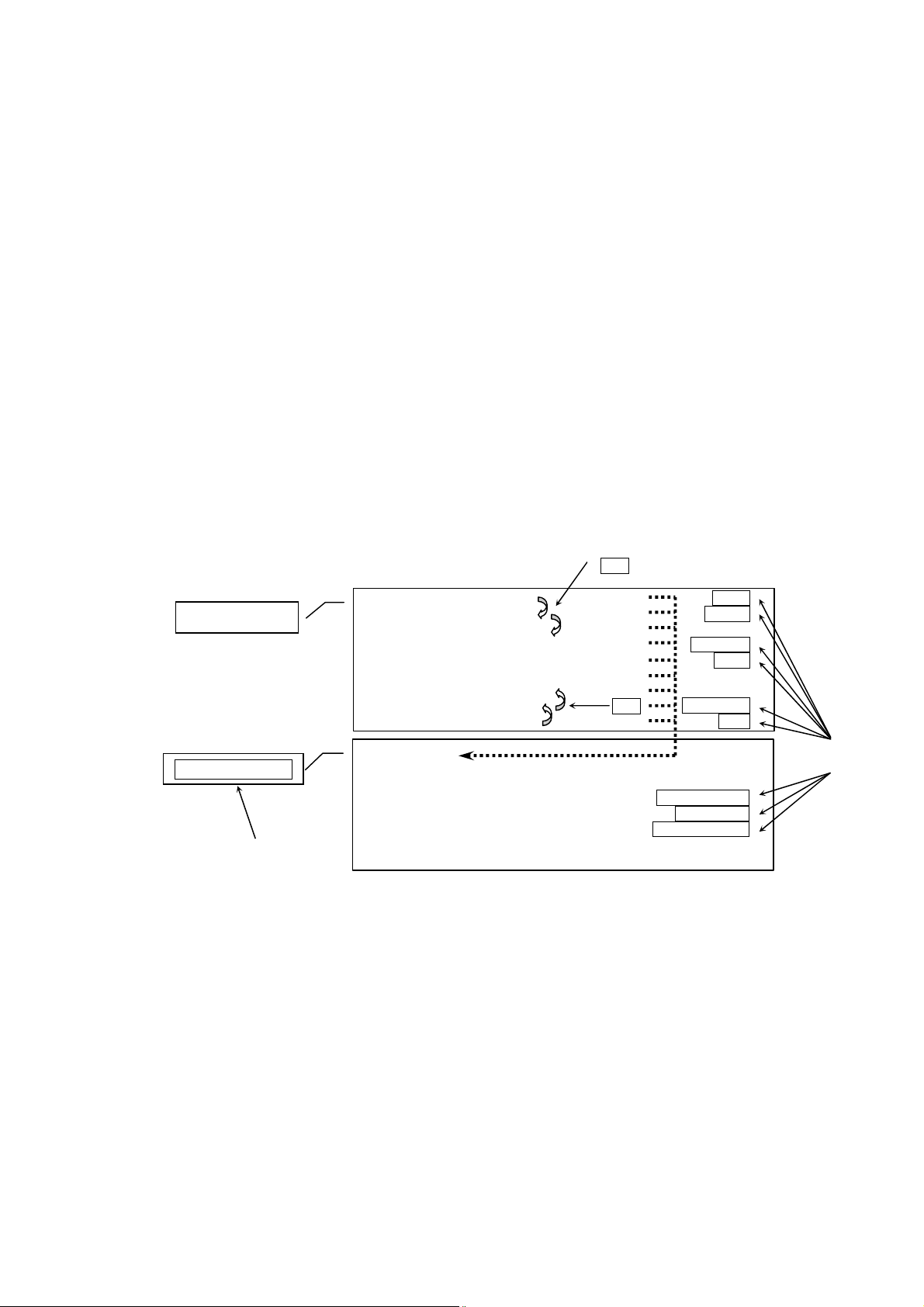
Usage front panel
Edit Channel Name
Key on remote control for
direct access of function
There are four keys at the front panel to control the MAP 1. Although most of the setup
can be done using those keys, the included remote control provides much more comfort
(refer to sections ' Audionet System Remote Control' and 'Setup').
The power key is used to switch on/off the MAP 1. To change volume or any settings in
the setup menus, please press the up and down keys. With the set key you skip through
the menu items of the setup menus. If you press and hold the set key for more than two
seconds, it will get you to the next setup menu. For navigating through the menus using
the remote control, please refer to chapter ' Audionet System Remote Control', section
'Navigate through a menu'.
Example: Navigating through menus
Level Setup
Channel Setup
key on remote control for
direct access of menu
Adjust Channel Offset Left Front Front
Adjust Channel Offset Center Center
Adjust Channel Offset Right Front
Adjust Channel Offset Right Surround Surround
Adjust Channel Offset Right Back Back
Adjust Channel Offset Left Back
Adjust Channel Offset Left Surround
Adjust Channel Offset Subwoofer Subwoofer
Adjust Channel Offset LFE Mix LFE
Internal Decoder
Set Video Input
Channel Offset Adjust
Set Listening Mode Listening Mode
Set Digital Filter Digital Filter
Set Dynamic Range Dynamic Range
Set Dual Mono
An overview of all menus and their functions is provided on the next page. Please refer
to example above as legend.
Before describing all menus and their menu items, the functions of the remote control
are explained in detail. Please use the remote control or, as alternative, the keys at the
front panel to setup your MAP 1 according to your preferences.
set (short)
or Ch-
Ch+
set (long)
11
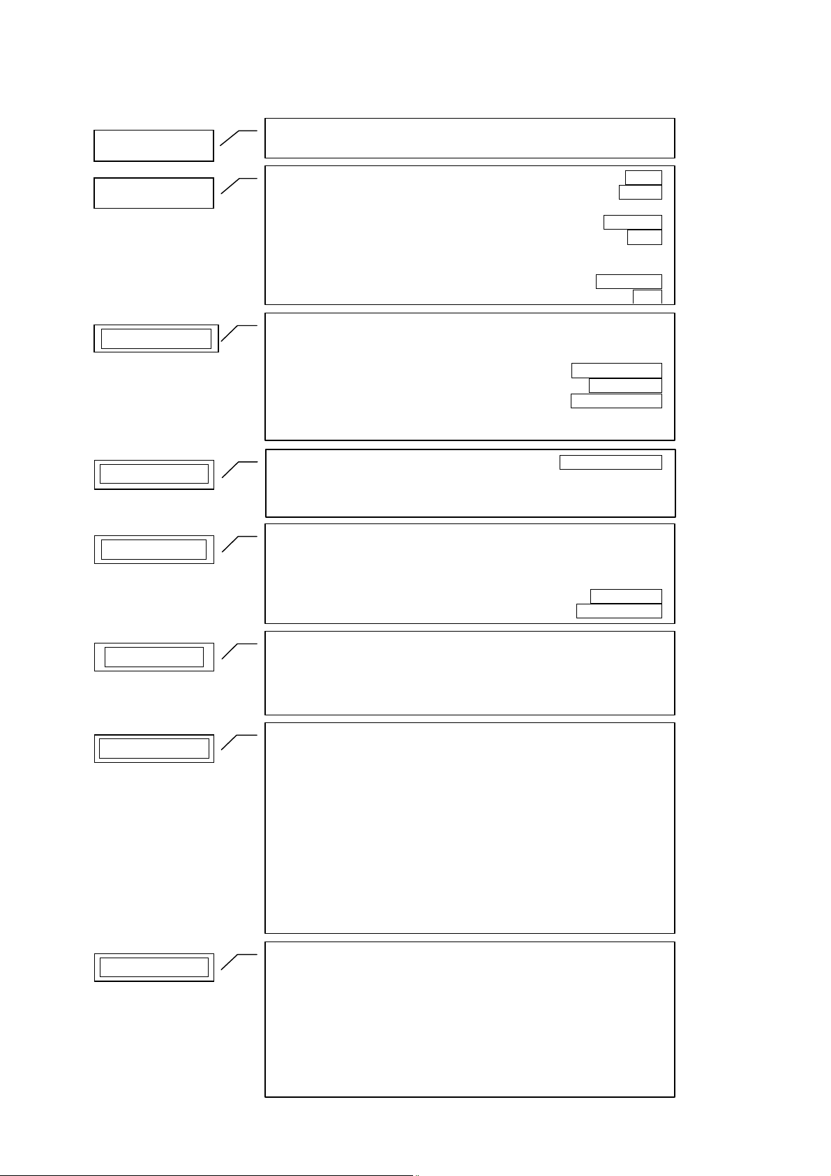
Overview of menu structure
Set L
istening Mode
Adjust Channel Offset LFE Mix
Edit Channel Name
Convert 2
-
Ch PCM to
Set Sync Output
Set Subwoofer Phase
Select Input
RUN Mode
Adjust Channel Offset Left Front Front
Level Setup
Channel Setup
Adjust Channel Offset Center Center
Adjust Channel Offset Right Front
Adjust Channel Offset Right Surround Surround
Adjust Channel Offset Right Back Back
Adjust Channel Offset Left Back
Adjust Channel Offset Left Surround
Adjust Channel Offset Subwoofer Subwoofer
Internal Decoder
Set Video Input
Channel Offset Adjust
Set Listening Mode Listening Mode
Set Digital Filter Digital Filter
Set Dynamic Range Dynamic Range
Set Dual Mono
LFE
Decoder Setup
Global Setup
Video Setup
Bass Manager
Set Dolby Pro Logic IIx mode for Multi-Channel Dolby / DTS Mode
Set Dolby Pro Logic IIx mode for 2-Channel
Set DTS Neo:6 Mode
Set Output Phase
Set Standby Text
Set AutoStart
Dolby Digital EX Mode
Set Display Brightness Dim Display
Set Digital Record Output DigiRec Select
Set Lip Sync Delay
Set Video Input
Set TV System
Set Progressive Output
Set Speaker Size Front
Set Speaker Size Center
Set Speaker Size Surround
Set Speaker Size Back Surround
Set Cross Over Frequency Front
Set Cross Over Frequency Center
Set Cross Over Frequency Sur
Set Cross Over Frequency Back
Set High Pass Q-Factor Front
Set High Pass Q-Factor Center
Set High Pass Q-Factor Sur
Set High Pass Q-Factor Back
Subwoofer
Delay Manager
Set Speaker Distance Left Front
Set Speaker Distance Center
Set Speaker Distance Right Front
Set Speaker Distance Right Sur
Set Speaker Distance Right Back
Set Speaker Distance Left Back
Set Speaker Distance Left Sur
Set Speaker Distance Subwoofer
Set Subwoofer Distance Offset
Set Distance Unit
12
Audionet System Remote Control
All functions of the MAP 1 can be controlled using the Audionet System Remote
Control Harmony Ultimate One. Furthermore, it is possible to control up to 14
additional devices with the Harmony Ultimate One.
13
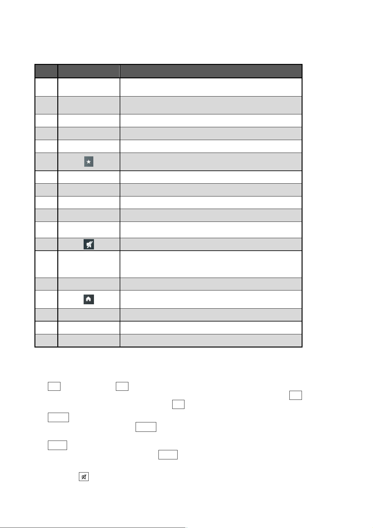
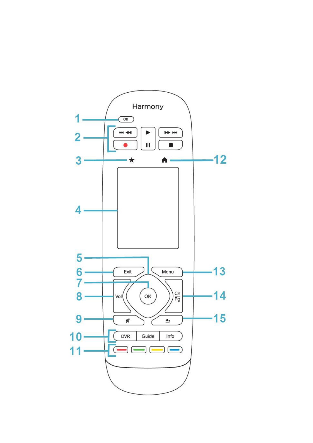
Key assignment Harmony Ultimate One
Home: displays all programmed Activities of Harmony
No. Key Function
1
Play Pause Stop
2
2
2
2
3
4
5
6
7
8
9
10
11
Off
REC
9 :
78
Exit
OK
Vol +
Vol -
DVR
Guide
Info
Switch off currently active Activity; press and hold key for
longer than 10 sec. to switch on/off remote control
Stars, pauses or stops playback of titles via USB Audio
input; Pause is not assigned
Not assigned
Skip to previous/next title (USB Audio playback only)
Not assigned
Favorites: see manual Logitech;
Not relevant for MAP 1
Touch screen, functions are labelled
Not assigned
Not assigned
Not assigned
Increases / decreases volume
Switch mute on / off
DVR: not assigned
Guide: switch on / off OSD
Info: activate Show function
Colour keys: not assigned
12
13
14
15
Menu
Ch
O
Ultimate One
Not assigned
Switch to next / previous input channel
Not assigned
1 Power key for use with Activities, turns all devices off that are included into the
current Activity. See separate user's manual of Harmony Ultimate One.
2 < stops playback. 4 starts playback. During playback, press key to pause
playback at current position. Press key again to resume play at this position. 9
skips back to beginning of previous title. : skips ahead to beginning of next title.
8 Vol+ increases volume, while the MAP 1 is in RUN mode. If the MAP 1 is inside
one of the setup menus, use Vol+ to select desired setup option. This key has the
same function as the key up on the front panel.
Vol- decreases the volume, while the MAP 1 is in RUN mode. If the MAP 1 is
inside one of the setup menus, use Vol- to select desired setup option. This key
has the same function as the key down on the front panel.
9 Press key to mute / un-mute. Muting is carried out smoothly, i.e. the volume is
stepped down or up gently.
14
10 Press key Info to activate the function Show of the MAP 1. This function
provides information on the current program format as well as output and speaker
configuration. For further information regarding display or On Screen Display
please refer to sections "Display" and "On Screen Display". If the On Screen
Display is off, it will be switched on automatically as long as the information is
presented after pressing the key Info .
To switch on / off the On Screen Displays (OSD) use key Guide . This key has the
same function as key OSD of the Harmony Ultimate One.
Note: OSD is only available on video outputs VIDEO and S-VIDEO.
14 Ch+ selects the next input channel if the MAP 1 is in RUN mode. Ch- selects
the previous input channel if the MAP 1 is in RUN mode.
Note:
· You can use the keys of point no. 2 above only while USB Audio playback via
digital audio input 7 USB AUDIO 7 . Please refer to section "USB Audio".
You will find help for setting up your Logitech Harmony Ultimate One on the internet
on Logitech's webpage:
www.logitech.com/support/harmony-ultimate-one
http://support.myharmony.com/en/article.htm?faqid=s-a-2166
Download the user manual from here:
http://cdn-www.myharmony.com/files/harmonyultimateone-usermanual-en.pdf
Using the touch screen
Tap on the Symbol above the touch screen of your Harmony Ultimate One to get a
list of all your Activities. Tap now on the symbol on the lower right and then on the
key Devices . The screen will give you a list of all programmed devices to be
controlled by your Harmony Ultimate One. Scroll through the list with an up or down
wipe and press then the key MAP 1 in order to control your MAP 1 with the Harmony
Ultimate One. The Device mode gives you access to all remote control commands your
MAP 1 understands. The following will discuss these commands in detail.
15
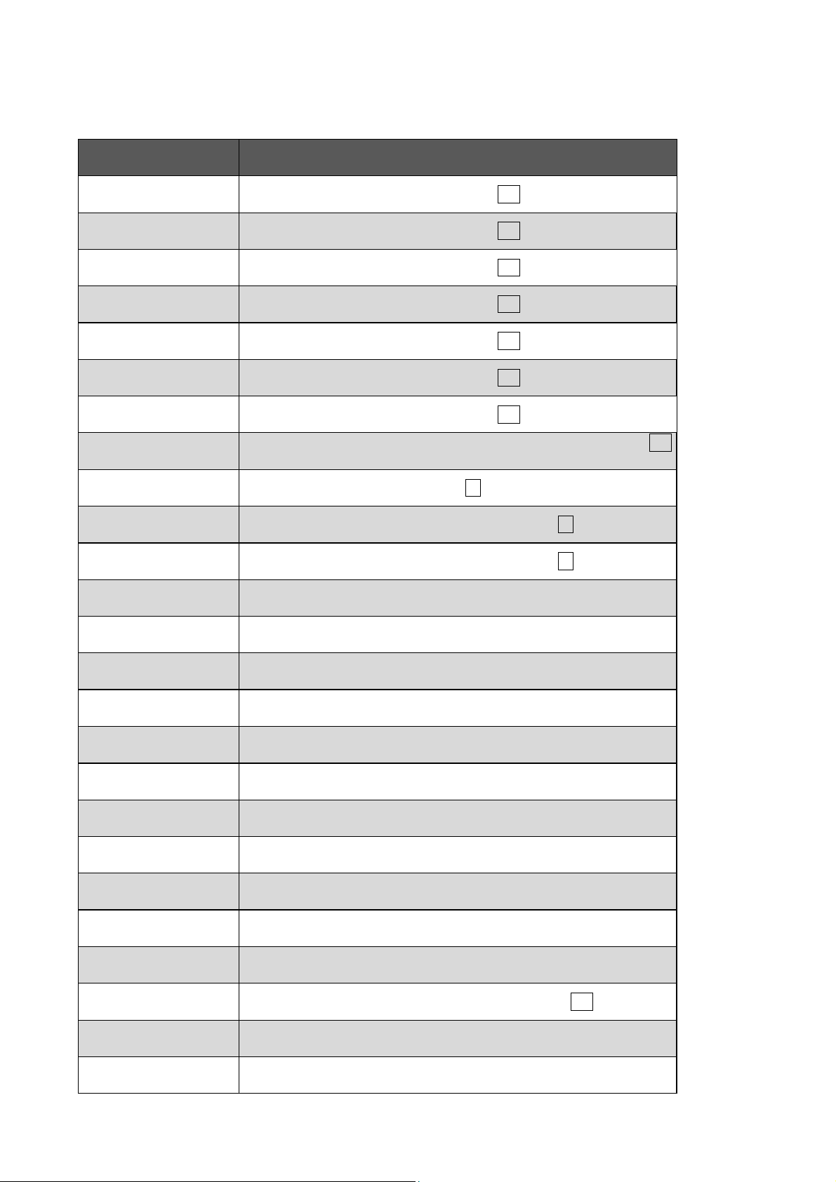
Keys of the touch screen
Key Function
Digital In 1
Digital In 2
Digital In 3
Digital In 4
Digital In 5
Digital In 6
Digital In 7
Ext. 8ch. In
USB Audio In
Analog In 1
Analog In 2
Dynamic Range
Select digital audio input Digital Audio IN 1 12 directly
Select digital audio input Digital Audio IN 2 12 directly
Select digital audio input Digital Audio IN 3 12 directly
Select digital audio input Digital Audio IN 4 12 directly
Select digital audio input Digital Audio IN 5 12 directly
Select digital audio input Digital Audio IN 6 12 directly
Select digital audio input Digital Audio IN 7 12 directly
Select analog 8-channel audio input 8-CHANNEL ANALOG IN 10
directly
Select digital audio input USB AUDIO 7 directly
Select analog audio input Analog In LEFT 1 / RIGHT 1 9 directly
Select analog audio input Analog In LEFT 2 / RIGHT 2 9 directly
Adjust dynamic range
Equalizer on/off
Dolby / DTS Mode
PCM Direct
Listening Mode
Front
Center
Surround
Back
Sub
LFE
Digital Rec
Select
Dim Display
Switch on/off digital parametric equalizer
Adjust Dolby or DTS modes
Switch on/off mode "PCM Direct"
Select Listening Mode
Adjust volume level of Front channels
Adjust volume level of Center channel
Adjust volume level of Surround channels
Adjust volume level of Back Surround channels
Adjust volume level of Subwoofer channel
Adjust volume level of LFE channel
Select output signal of digital outputs Digital Audio OUT 13
Adjust display brightness
Digital Filter
Select digital oversampling filter for Front channels L/R
16
OSD
Swiches on/off the On Screen Display
Load Setting
Save Setting
Global Setup
Channel Setup
Bass Manager
Delay Manager
Video Setup
Test Tone
MPE +
MPE -
Freq +
Freq -
Load a User Setting
Save a User Setting
Enter menu for global setup options
Enter menu channel specific setup options
Enter menu of the Bass Manager
Enter menu of the Delay Managers
Enter menu for video setup options
Switch on/off the test tone
Select next filter of the current input channel (digital equalizer)
Select previous filter of the current input channel (digital equalizer)
Increase center frequency of current filter (digital equalizer)
Decrease center frequency of current filter (digital equalizer)
Gain +
Gain -
Q +
Q -
Power Toggle
Power On
Power Off
Increase gain of current filter (digital equalizer)
Decrease gain of current filter (digital equalizer)
Increase Q factor of current filter (digital equalizer)
Decrease Q factor of current filter (digital equalizer)
Switches on/off the MAP 1 (toggle power)
Switches on the MAP 1
Switches off the MAP 1
Important
· Please find detailed information to the keys of the touch screen in the following.
17
 Loading...