

Audionet DNP User Manual
Digital Network Amplifier
User's Manual


3
Contents
1 Preface ............................................................................... 7
1.1 Included ........................................................................................ 8
1.2 Transport ..................................................................................... 8
2 Overview front panel ......................................................... 9
3 Overview back panel ....................................................... 10
4 Installation and power supply ........................................ 11
4.1 Placement ................................................................................... 11
4.2 Mains connection ....................................................................... 11
4.3 Orientation of mains plug ......................................................... 12
5 Inputs and outputs .......................................................... 13
5.1 Audio inputs ............................................................................... 13
5.1.1 Analog inputs .............................................................................. 13
5.1.1.1 Optional phono input .................................................................. 13
5.1.2 Digital input ................................................................................ 14
5.1.2.1 Audionet HighBit input .............................................................. 14
5.2 Audio output .............................................................................. 15
5.2.1 Speaker terminals ........................................................................ 15
5.2.2 Preamplifier output ..................................................................... 15
5.2.3 Headphones Socket ..................................................................... 15
5.3 Other connections ..................................................................... 16
5.3.1 Network, USB, WLAN ............................................................... 16
5.3.2 USB Audio .................................................................................. 16
5.3.3 FM Antenna Connection ............................................................. 17
5.3.4 Audionet Link ............................................................................. 17
5.3.5 External power supply EPS G2 or EPX ...................................... 17
5.3.6 Additional earth connection ........................................................ 18
5.3.7 Control connections .................................................................... 18
6 Usage ............................................................................... 19
6.1 Basic operations ......................................................................... 19
6.1.1 Powering up ................................................................................ 19
6.1.2 Switching on and off ................................................................... 20
6.1.3 Mains phase detection ................................................................. 21

4
6.1.4 Using Audionet Link ................................................................... 22
6.1.5 Control elements on the front panel ............................................ 22
6.2 Detail operations ........................................................................ 23
6.2.1 Display ........................................................................................ 23
6.2.1.1 Analog input channel .................................................................. 23
6.2.1.2 Digital input channel ................................................................... 23
6.2.1.3 FM tuner ...................................................................................... 24
6.2.1.4 NET input .................................................................................... 24
6.2.2 Volume control ............................................................................ 26
6.2.3 Muting ......................................................................................... 26
6.2.4 Input selection ............................................................................. 27
6.2.5 FM tuner ...................................................................................... 28
6.2.6 NET input .................................................................................... 28
6.2.6.1 Internet radio ............................................................................... 28
6.2.6.2 USB ............................................................................................. 29
6.2.6.3 UPnP server ................................................................................ 30
6.2.7 USB Audio .................................................................................. 30
7 Audionet system remote control .................................. 31
7.1 Key assignment DNA ................................................................ 33
7.2 Screen 1 ...................................................................................... 34
7.3 Screen 2 ...................................................................................... 35
7.4 Screen 3 ...................................................................................... 35
7.5 Screen 4 ...................................................................................... 36
7.6 Screen 5 ...................................................................................... 37
8 Device setup .................................................................... 38
8.1 Overview device menu .............................................................. 39
8.2 Global setup ............................................................................... 40
8.2.1 Headphones ................................................................................. 40
8.2.2 Display ........................................................................................ 41
8.2.3 Balance Left/Right ...................................................................... 42
8.2.4 Preamplifier output ...................................................................... 43
8.2.5 Auto start ..................................................................................... 44
8.2.6 By-Pass channel .......................................................................... 45
8.2.7 Phono Card .................................................................................. 47
8.2.8 Power-off mode ........................................................................... 48
8.3 Channel setup ............................................................................ 49
8.3.1 Channel name .............................................................................. 49
8.3.2 Volume offset .............................................................................. 49
8.3.3 Digital equalizer setup ................................................................. 50

5
8.3.4 Trigger out ................................................................................... 51
8.3.5 ADC attenuation ......................................................................... 52
8.3.6 DC Servo ..................................................................................... 53
8.4 Bass manager ............................................................................. 54
8.4.1 Loudspeaker ................................................................................ 54
8.4.2 X-Over ........................................................................................ 55
8.4.3 Subwoofer volume offset ............................................................ 55
8.4.4 Subwoofer phase ......................................................................... 56
8.5 Delay manager ........................................................................... 57
8.5.1 Speaker distance .......................................................................... 57
8.5.2 Virtual subwoofer offset ............................................................. 57
8.6 Network setup ............................................................................ 58
8.6.1 Manage Network ......................................................................... 59
8.6.1.1 Restart Network Driver ............................................................... 59
8.6.1.2 Save & Apply Settings ................................................................ 59
8.6.1.3 Load Factory Defaults ................................................................ 60
8.6.2 Connection Type ......................................................................... 60
8.6.3 DHCP .......................................................................................... 61
8.6.4 IP Address ................................................................................... 61
8.6.5 IP Mask ....................................................................................... 62
8.6.6 Gateway ...................................................................................... 62
8.6.7 DNS ............................................................................................. 63
8.6.8 RCP port ...................................................................................... 63
8.6.9 Wireless setup ............................................................................. 64
8.6.9.1 SSID ............................................................................................ 64
8.6.9.2 Wireless security ......................................................................... 65
8.6.9.3 WPA pass phrase ........................................................................ 66
8.6.9.4 WEP authentication .................................................................... 66
8.6.9.5 WEP key index ........................................................................... 67
8.6.9.6 WEP key 0-3 ............................................................................... 68
8.6.10 Example for Network setup ........................................................ 69
8.7 User settings ............................................................................... 73
8.7.1 Save user setting .......................................................................... 73
8.7.2 Load user setting ......................................................................... 73
8.8 Device info .................................................................................. 74
9 Security system ............................................................... 75
10 Additional information .................................................... 76
10.1 Glossary ...................................................................................... 76
10.2 Link collection ........................................................................... 78

6
10.2.1 Wireless security ......................................................................... 78
10.3 Equalizer filter type .................................................................. 79
10.3.1 Peak-Filter ................................................................................... 79
10.3.2 High shelf filter ........................................................................... 79
10.3.3 Low shelf filter ............................................................................ 79
10.3.4 High-pass filter 2nd order ............................................................. 80
10.3.5 Low-pass filter 2nd order ............................................................. 80
10.3.6 High-pass filter 1st order .............................................................. 80
10.3.7 Low-pass filter 1st order .............................................................. 80
10.4 Error handling (FAQ) ............................................................... 81
10.5 Security advice ........................................................................... 82
10.6 Factory defaults ......................................................................... 83
10.7 Specifications ............................................................................. 85

7
1 Preface
The Audionet Team congratulates you on your purchase of this unit.
Audionet components are no marketing products, they are authentic.
Conceived and developed with scientific inspiration, professional engineering expertise and a passion for achieving the perfect sound. They are
unique creations designed to inspire musical enjoyment and have an excellent reputation amongst all connoisseurs throughout the world. Each
and every one of our precision-manufactured devices is individually
crafted at our Bochum works by our experienced and passionate workforce.
But before you start listening to your new Audionet DNA, please read
this manual carefully so you are able to use and enjoy all functions of this
unit without drawback on music quality.

8
1.1 Included
Included you will find the following items:
· The stereo network amplifier DNA
· The user's manual
· one standard mains cord
· one green-yellow cord for an additional earth connection
· F-adaptor for FM connection
· WLAN antenna
· Audionet System Remote Control Harmony One
1.2 Transport
Important
· Please transport the DNA only in the included package.
· Always use the provided cloth bag to prevent scratches on the casing
· Please allow the DNA to adapt to the climatic conditions in your
listening room before you switch on the unit for the first time after
transport.
9
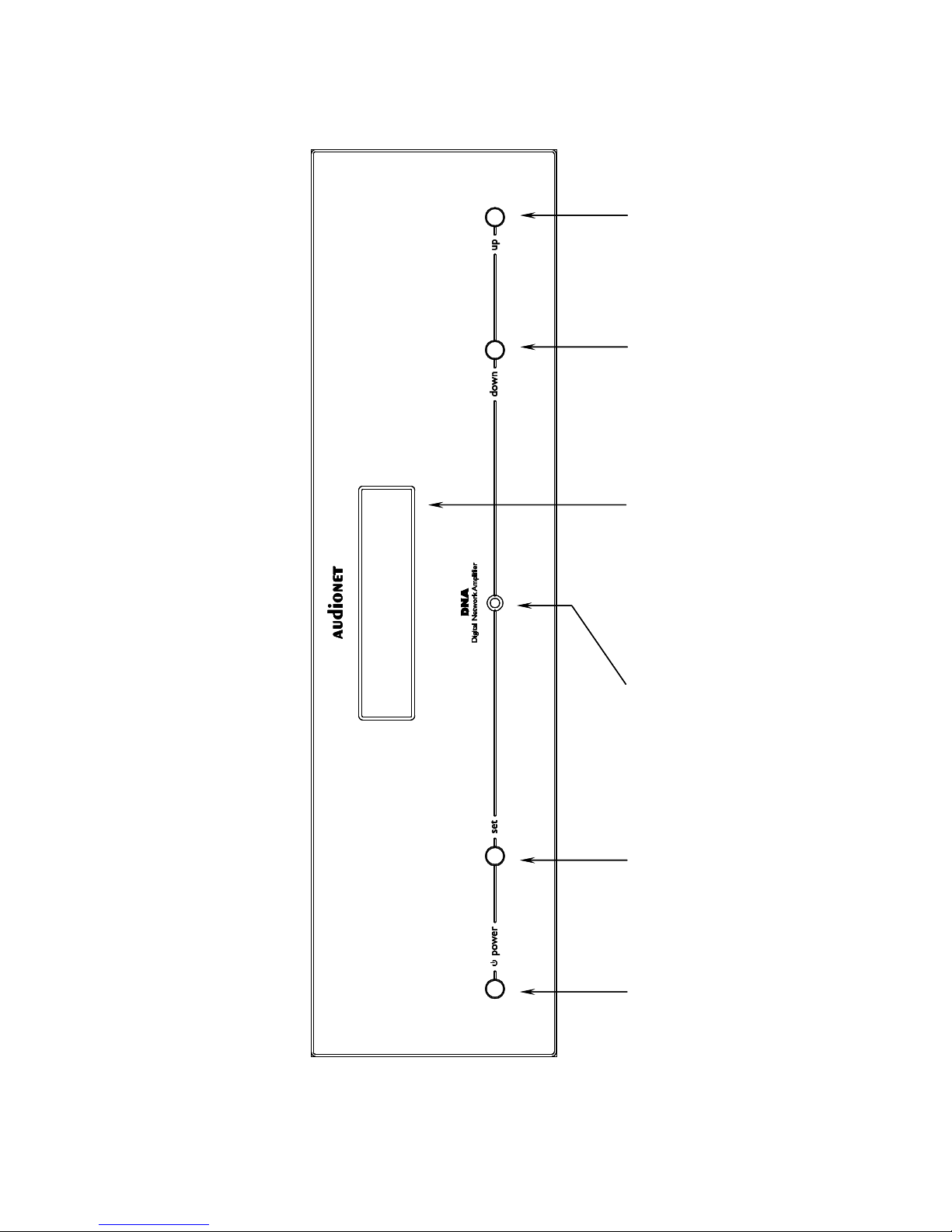
2 Overview front panel
power
key
A
USB
-
set
key
up
key
down
key
IR remote
control receiver
Display
10
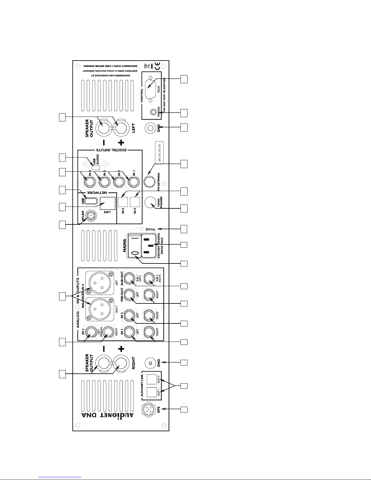
3 Overview back panel
1
25
24
2 3 4 5 6 7 8
9
12 11 13 14 15 16
17 19 20 21 22 23
10
1
5-pin connector for external power supply EPS 2 Audionet Link output
OUT 1, OUT 2
3
Earth connector for turntable (phono) 4 Cinch input no. 1, left/right 5 Cinch input no. 2, left/right 6 Preamplifier output
PRE OUT
, left/right
7
Subwoofer cinch output
SUB OUT
,
SUB1/SUB2 or multiroom out left/right
8
Mains switch
10 Mains input
11 Marking mains phase
12 Headphones output
13 Digital input no. 5, no. 6, optical
14 FM antenna input
15 additional earth connector
16 Trigger output (5 or 12 Volt)
17 Serial control port RS232
18 Speaker output left
18 USB Audio Input
19 Digital input no. 1, no. 2
no.3 and no. 4, electrical
20 USB connector
21 Ethernet connector LAN
22 Connector WLAN antenna
23 Balanced input (XLR) no. 4, left/right
24 Cinch input no. 3, left/right (opt. phono) 25 Speaker output right
18

11
4 Installation and power supply
Important
· During connecting and removing of sources or amplifiers to the
DNA all units of your audio system have to be switched off to prevent damage of the DNA or any of the other connected units.
· Please make sure that all cables are in absolute best conditions!
Broken shields or short-cut cables could damage the DNA and/or
any other connected unit.
4.1 Placement
Important
· It is recommended to place the DNA into a high quality rack or onto
a stable table.
· Do not expose the unit to direct sunlight.
· Do not cover the ventilation slots.
· Do not place the DNA in close range to heat sources like radiators.
· Do not place the DNA on top of other units, especially not on top of
power amplifiers, preamplifiers or similar devices that produce heat.
Both units could suffer damage from thermal overload.
· Do not place other units on top of the DNA. Both units could suffer
damage from thermal overload.
· Do not use the unit in places where it is exposed to vibrations.
· Do not place the unit close to loudspeakers or into the corner of a
room where it is exposed to high levels of sonic energy, which might
reduce the sound quality of the unit.
4.2 Mains connection
The mains input 9 * is on the back panel of the DNA. To connect the device
to mains use the included mains cord. If you prefer to use a different power
cord make sure that it meets the specifications for your home country.
Important
· The electrical specifications of your home country must meet the
electrical specifications printed onto the back panel.
*
see numbers in section "3 - Overview back panel" on page 88.
12
· The DNA is a Class I unit and must be earthed. Please ensure a stable
earth connection. Phase (hot pin) is marked on the back panel phase
10 .
· If you connect the mains cord please make sure that the mains switch
8 on the back panel is switched off.
· Never pull the mains plug while the DNA is switched on! Before you
pull the mains cord off its socket 9 on the back panel, power down
the unit to stand-by mode using power key, and switch off the unit
using mains switch 8 .
Only in cases of extended absence – like vacations – or if massive trouble
on the mains power grid is to be expected you should switch off the DNA
from the mains using mains switch 8 . Then, to disconnect the unit completely from mains power grid, pull the mains plug.
Tip
· The use of high quality mains cords can improve sound quality. Ask
your local dealer for more information.
4.3 Orientation of mains plug
The correct polarization of mains is important for reasons of audio clarity
and stability. Please connect the mains cord so that the hot pin of the wall
outlet is connected to the pin of the mains input 9 marked phase 10 .
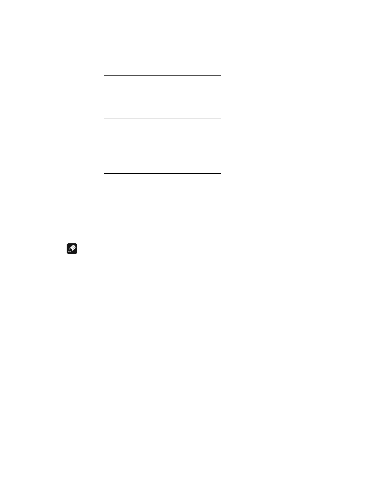
Your Audionet DNA is able to detect a wrong polarization of the mains
plug during start-up. If the message
appears in the display, switch off the unit and flip the mains plug in the
wall outlet (see section "6.1.3 - Mains phase detection" on page 21).
► Attention: ◄
► Mains phase incorrect ◄
13
5 Inputs and outputs
Important
· During connecting and removing sources or amplifiers to the
DNA all units of your audio system have to be switched off to
prevent damage of the DNA or any of the other connected units.
· Please make sure that all cables are in absolute best conditions!
Broken shields or short-cut cables could damage the DNA and/or
any other connected unit.
5.1 Audio inputs
5.1.1 Analog inputs
The DNA is equipped with three unbalanced cinch inputs IN 1 4 *, IN 2
5 , IN 3 24 and with a balanced input IN 4 23 for connecting signal
sources at line level.
Please connect the left and right input of the same number printed on the
back panel of the DNA to the corresponding output of the source you
would like to connect to the DNA.
5.1.1.1 Optional phono input
The DNA can be upgraded with a phono preamplifier. Use input IN 3
24 to connect the turntable. Please connect the ground wire of the turntable to the terminal GND 3 .
Important
· If the DNA is equipped with the optional phono module, input IN 3
24 must only be used to connect a turntable.
· Never use IN 3 24 as input for By-Pass mode, if the optional phono
module is installed.
· If the DNA is equipped with the optional phono module, it has to be
signed in to the system in order to be configurable. For further information see section "8.2.7 - Phono Card" on page 47.
*
see number in section "3 - Overview back panel" on page 88.
14
5.1.2 Digital input
Connect your digital sources to the electrical (coaxial) digital input IN 1
to IN 4 19 * or to the optical (TosLink) digital input IN 5 and IN 6 12 .
5.1.2.1 Audionet HighBit input
In order to send audio data across the Audionet HighBit interface to your
DNA, connect your source device (e.g. ART G3 or VIP G3) with two
digital cords to the digital inputs IN 1 and IN 2.
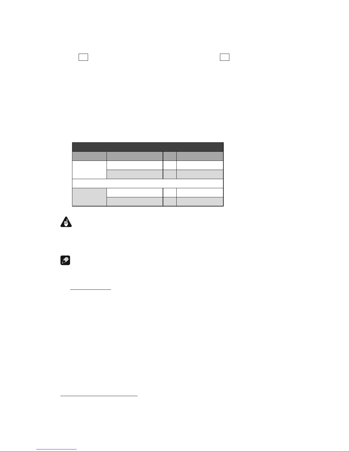
The following table shows how to connect Audionet HighBit-capable
devices to the DNA:
Audionet HighBit
Devices Output DNA Input
VIP G3
Digital OUT 1
’
Digital IN1
Digital OUT 2
’
Digital IN2
ART G3
Digital OUT 1
’
Digital IN1
Digital OUT 2
’
Digital IN2
Important
· Only if both connections are established and Audionet HighBit mode
is activated on your source device, you can transmit audio data with
all sampling rates and full resolution.
Note
· Check the corresponding section in user's manual for Audionet ART
or VIP. User's manuals are available for download on our website
www.audionet.de.
*
see number in section "3 - Overview back panel" on page 88.
15
5.2 Audio output
5.2.1 Speaker terminals
Connect your speakers to the gold plated terminals Speaker Output Left
17 and Speaker Output Right 25 on the back panel of the DNA. You
can use banana plugs or spades as well as simple cable ends. Look out for
the correct connection of your speaker cables. Usually, the terminals of
your speakers are marked + and -. The DNA uses the same marks.
Note
· Wrong speaker polarization will result in severe loss of sound quality.
· In case you would like to bi-wire your speakers please insert the ca-
ble to the tweeters from the rear using banana plugs and mount the
cables to the bass speakers from the side. In doubt please ask your
dealer for assistance.
Important
· Although the DNA has an effective protection system to prevent
damage to the circuits, switch off the unit while working on the
speakers and/or audio cables.
· The nominal loudspeaker impedance should be at least 4 Ohms or
higher.
· Never use force or tools tightening the terminal screws.
5.2.2 Preamplifier output
The DNA is equipped with two pairs of RCA preamplifier outputs PRE
OUT 6 and SUB OUT 7 to connect e.g. an additional amplifier and
one or two subwoofers. The SUB OUT 7 preamplifier output can be
switched to multiroom output with separate volume control.
Use the RCA connection PRE OUT 6 with high quality cable (e.g.
Audionet C100) for bi-amping. The PRE OUT 6 can also be switched to
fixed volume for recording purpose.
Note
· Please refer to section "8.2.4 - Preamplifier output" on page 43 for
detailed information on preamplifier output modes.
5.2.3 Headphones Socket
A 6.3 mm headphones socket HEADPHONES 11 is located at the rear
of your DNA. The signal at this socket can be switched on and off to
allow the headphones to be plugged in permanently. Switching is easily
done in the system menu, please refer to "8.2.1 - Headphones" on page
40.

16
5.3 Other connections
5.3.1 Network, USB, WLAN
The Ethernet port LAN 21 * is a standard RJ45 socket for network cables
(Cat-cable, 10/100 Mbit BASE-T).
The WLAN port WLAN 22 uses a SMA connection to attach the provided WLAN antenna. With the articulated joint the antenna can be
turned into two directions.
The USB port USB 20 is a TYPE-A socket (USB 2.0) for external hard
drive, USB sticks etc.
Note
· We recommend using a wired network connection for best data trans-
fer rate and to provide high stability in control with our software.
5.3.2 USB Audio
The USB Audio port USB AUDIO 18 is a mini-USB TYPE-B-socket.
With the USB Audio connection you are able to connect your DNA with
a USB cable directly to a PC. Thus you can use your DNA as the sound
device / playback device for your PC. Playback operates in asynchronous
mode, that means the DNA uses its own clock and you are able to enjoy
your music without diminishing sound quality.
For using USB Audio the required driver needs to be installed on your
PC. For Apple devices using Mac OS X 10.6.4 and higher a suitable
driver is included within the operating system. To receive the driver for
Windows based systems please contact us via service@audionet.de.
Note
· The driver is packed into a zip-file. To install the driver unpack the
zip-file into a folder of your choice. Then open the chosen folder and
start the installation process executing the file setup.exe.
· During the installation process all occurring security warnings can be
confirmed with 'OK'.
· During the installation process your Audionet device has to be con-
nected with your PC via an USB cable.
· After successful installation you can choose your DNA as the sound
device / playback device of your PC. For configuration open the system preferences of your PC.
· Pay attention to the length of the USB cable. If the cable is too long
you might diminish sound quality and / or experience dropouts during
playback.
*
see number in section "3 - Overview back panel" on page 88.

17
5.3.3 FM Antenna Connection
Your device has an F-series connector 13 for antenna connection. An
adaptor to coaxial socket is delivered separately. This port is specified for
75 Ohm FM antenna or analog cable TV connection.
5.3.4 Audionet Link
For your convenience, the DNA can switch on/off all other Audionet
units (e.g. power amplifiers) connected via Audionet Link by a simple
touch on the remote control or the power key on the front panel.
You only need a simple optical TosLink cable. Connect the Audionet
Link output Link OUT 2 of your DNA to the Audionet Link input of the
unit to be controlled.
The DNA is equipped with two Audionet Link outputs Link OUT 2 .
Link OUT 1 is always on while the DNA is switched on. However,
Audionet Link output Link OUT 2 is controlled depending on the settings
for the headphones output. Please refer to section "8.2.1 - Headphones"
on page 40.
Therefore, use Audionet Link output Link OUT 2 in order to connect
power amplifiers to the DNA via Audionet Link. Connect units you
would like to control independently from the headphones settings (e.g.
tuner, CD player, etc) to Audionet Link output Link OUT 1.
Tip
· Audionet source units and power amplifiers are usually equipped not
only with an Audionet Link input, but additionally with an Audionet
Link output to connect further Audionet devices to be controlled via
Audionet Link in a daisy chain. Connect this Audionet Link output to
the Audionet Link input of the next Audionet unit using a simple optical TosLink cable allowing you to switch on/off your complete
Audionet system by your Audionet amplifier DNA.
5.3.5 External power supply EPS G2 or EPX
In order to use the optional external power supply Audionet EPS G2 or
Audionet EPX connect it with the delivered cable to socket EPS 1 on the
back panel of your DNA. Connect both (!!) units (DNA and EPS G2 /
EPX) to mains. First, switch on the DNA with the mains switch 8 on its
back panel. Then switch on the EPS / EPX. Now the DNA is ready to use
(stand by mode).
Switch on the DNA with the power key on the front panel or keys
Power On or Power Toggle of the Audionet System Remote Control Harmony One. The Audionet EPS G2 / EPX will then be automatically switched on time-delayed.
To disconnect the DNA and EPS G2 / EPX from mains, switch the DNA
into stand-by mode. Use the power key on the front panel or the keys
Power Off or Power Toggle on the system remote control. First,
switch off the DNA with the mains switch 8 on the back panel, and then
18
switch off the EPS G2 / EPX. Now you can disconnect the mains and
EPS G2 / EPX connection cables.
Important
· Never switch on or off the EPS G2 / EPX on its back panel while
the DNA is operating!
· The DNA is only to be used with EPX or with EPS G2 from serial
number 12.23.10 on up. For EPS or EPS G2 with older serial
numbers there is no guarantee for proper functionality!
· Before using the DNA in combination with the external power
supply EPS G2 or EPX please read the user's manual of the
EPS G2 or EPX carefully!
5.3.6 Additional earth connection
An optional green-yellow cord for the additional earth connection is
available from Audionet. Attach this cord to the earth connector 14 on
the back panel of the DNA and put the plug into the mains socket right
beside the mains cord of your DNA. This ensures an additional and stable
earth connection resulting in a better sound.
On the second ground connection GND 3 you can connect the ground
wire from a turntable (phono).
5.3.7 Control connections
Use trigger output TRIGGER 15 to control (e.g. switch on/off) non
Audionet devices. If you switch on the DNA from stand-by mode, the
trigger output 15 provides a signal of 12 Volts DC (see section "8.3.4 -
Trigger out" on page 51), which can be re-configured to 5 Volts DC.
The serial connection RS232 16 is an additional control port to your
DNA e.g. for house automation systems (Crestron or the like).
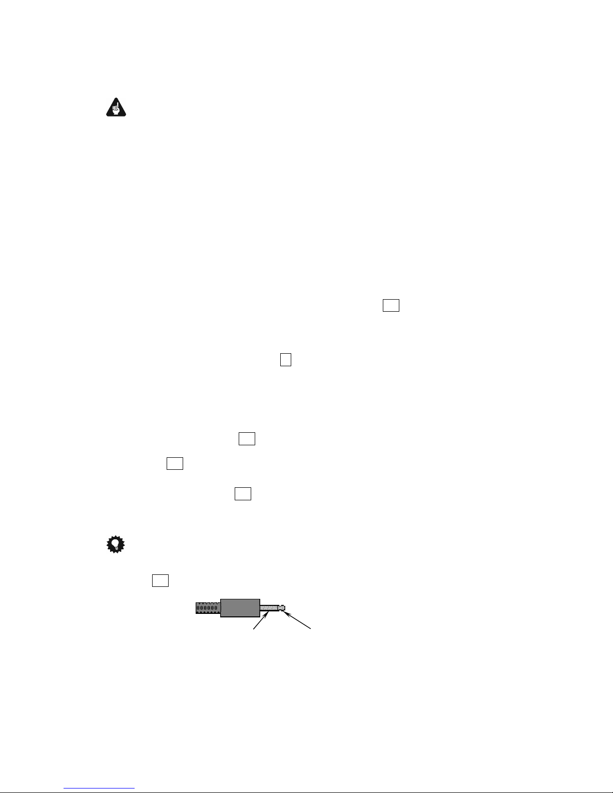
Tip
· Use a 3.5 mm telephone mono plug to connect a device to the trigger
output 15 of your DNA. The pinning is as follows:
Switching Voltage
12V or 5V DC
Ground

19
6 Usage
All functions of the DNA are microprocessor controlled. This guarantees
highest precision, exclusive functions, easy handling and protection
against operating errors.
6.1 Basic operations
6.1.1 Powering up
First of all, please make sure your DNA is connected correctly to your
signal sources, power amplifier(s) and mains (see section "4 -
Installation and power supply" on page 11 and "5 - Inputs and outputs" on page 13).
The DNA is a stand-by unit. Please operate the mains switch 8 on the
back panel. The display shows a welcome message for a brief moment.
After that the DNA is in stand-by mode.
Only in cases of extended absence (like vacations) or if massive trouble
on the mains power is to be expected (e.g. thunder storms) it is recommended to disconnect the DNA from the mains. While the DNA is in
stand-by mode, operate mains switch 8 on the back panel. The display
will go dark. To disconnect the DNA from mains completely, you have to
pull the mains cord off the mains jack 9 .
Important
· Before you switch off the DNA from mains, power down and dis-
charge completely all units connected to the outputs of the DNA.
20
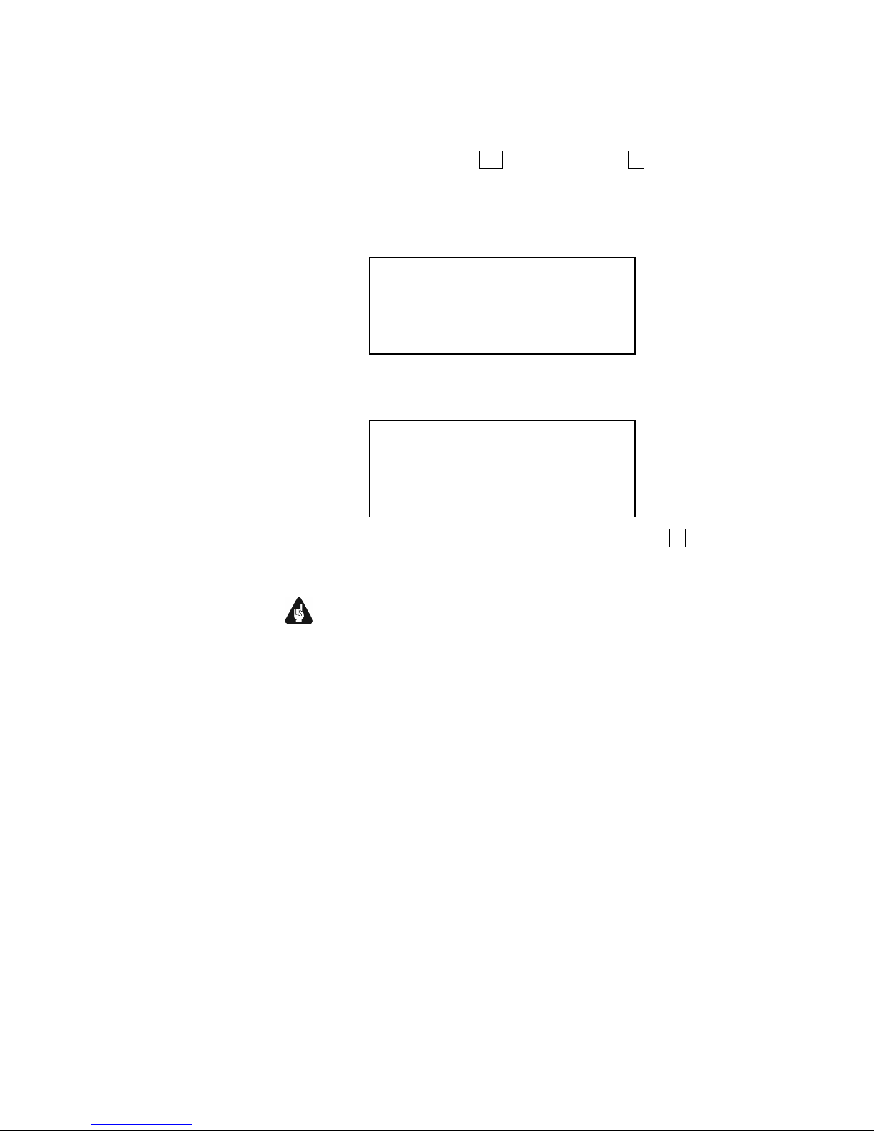
6.1.2 Switching on and off
To power up the DNA from stand-by mode, press the power key on the
front panel. The DNA issues the message:
In case the mains plug has the incorrect polarization a warning will appear in the display (see section "4.3 Orientation of mains plug" on page
12). After that the unit is in normal operating mode and ready to use.
If you would like to switch off the unit, please press the power key on the
front panel. The display shows the message
and the unit enters stand-by mode.
Note
· Of course, you may switch on/off the DNA with the Audionet System
Remote Control Harmony One. For detailed information please refer
to section "7.6 - Screen 5" on page 37.
Going to sleep ...
Waking up ...
21
6.1.3 Mains phase detection
The correct polarization of mains is important for reasons of audio clarity
and stability. Please connect the mains cord with the hot pin of the wall
outlet to the pin marked phase 10 of the mains input 9 on the back
panel. The DNA recognizes the incorrect polarization of the mains plug
automatically. Right after switching on the unit from stand-by mode by
pressing the power key on the front panel the following message will
appear in the display in case the mains polarization is incorrect:
If you are alerted by the above message, switch off the unit by pressing
the power key. Please wait until the display no longer reads:
Disconnect the DNA from mains by operating the mains switch 8 . Now
pull the mains plug and re-insert it into the mains socket rotated by 180°.
If you switch on the unit again, the warning should not appear now.
Important
· If the DNA issues the mains polarization warning or no warning at all
for both positions of the mains plug, check the connection to earth of
your mains socket and mains cord. You have to ensure a stable
connection to earth for the mains phase detection of the DNA to
work correctly!
Going to sleep ...
► Attention: ◄
► Mains phase incorrect ◄

22
6.1.4 Using Audionet Link
Your DNA is equipped with two Audionet Link outputs Link OUT 1 2
and Link OUT 2 2 allowing you to switch on/off further Audionet units
(e.g. power amplifiers, CD player or tuner) connected via Audionet Link
(also see section "5.3.4 - Audionet Link" on page 17).
If the rest of your Audionet system is connected to your DNA via Audionet Link, all linked units will be automatically switched on/off as soon as
you switch on/off your DNA using the power key on the front panel or
the Audionet System Remote Control Harmony One.
Note
· The switch on/off signal of the Audionet Link output Link OUT 2 2
is issued depending on the headphones settings (see section "8.2.1 -
Headphones" on page 40).
· Please read section "5.3.4 - Audionet Link" on page 17. Also, con-
sult the user's manual of your Audionet components connected via
Audionet Link for further information.
· If you use Audionet Link to switch off other devices, please wait
until everything is in stand-by mode before you switch on again.
6.1.5 Control elements on the front panel
The front panel has four keys to control the DNA (see section "2 Overview front panel" on page 9). With these keys you can control all
functions as well as all setup options to adjust the unit to your preferences
(see section "8 - Device setup" on page 38).
power Use key to switch on/off the unit (see section "6.1.2 -
Switching on and off" on page 20).
set Press key shortly to change input channel (see section
"6.2.4 - Input selection" on page 27). Within a menu
press shortly to open a subfolder or to confirm and save
an adjustment.
Press the key for longer than two seconds to get into
system menu (see section "8 - Device setup" on page
38). Within a menu press long to step back and open the
superior folder or to dismiss an adjustment without saving.
down Push key to reduce volume, select previous input chan-
nel (see section "6.2.4 - Input selection" on page 27)
or change an option of the setup menu (see section "8 -
Device setup" on page 38).
up Push key to increase volume, select next input channel
(see section "6.2.4 - Input selection" on page 27) or
change an option of the setup menu (see section "8 -
Device setup" on page 38).
23
6.2 Detail operations
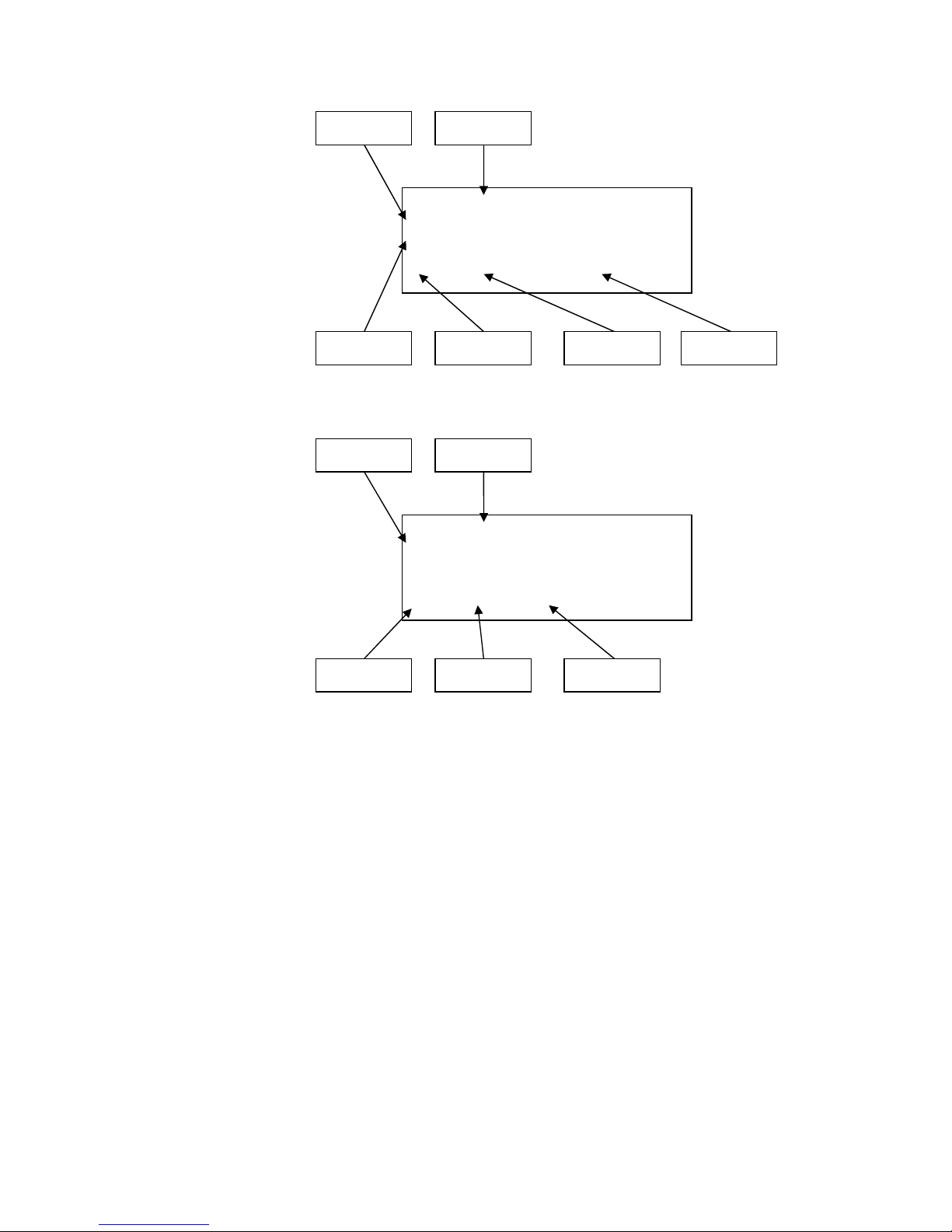
6.2.1 Display
The display provides the following information in the normal operating
mode.
Depending on which channel you chose, you get different information. If
there is more information to show you can switch display pages with the
Info key on system remote control Harmony One (see section "7.1 -
Key assignment DNA" on page 33). You will need it especially for the
NET input channel (see section "6.2.1.4 - NET input" on page 24). The
following illustrations will show you the differences between the input
channels. Your display could be different, because of your selected system adjustments.
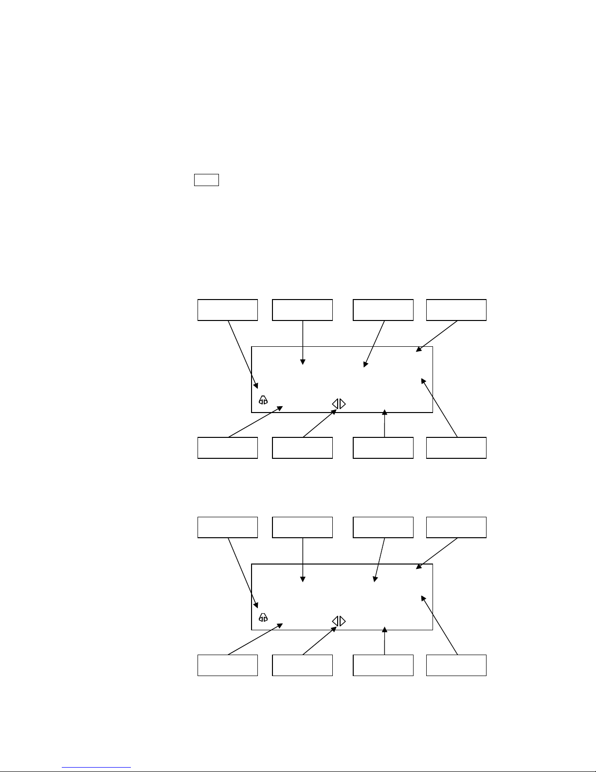
6.2.1.1 Analog input channel
6.2.1.2 Digital input channel
D 1
BAL Digital In 1
PCM 44.1kHz
Sub 1
-60 dB
Equalizer Input
Balance
(Left/Right)
Volume
Signal handling Headphones Channel name
Subwoofer /
Multiroom
EQ
AN
4
BAL Balanced IN 4
A/D Converted
Sub 1&2 S
mute
DC
Equalizer Input
Balance
(Left/Right)
Volume
Signal handling
DC servo
Headphones
Channel name
Subwoofer /
Multiroom
EQ
24
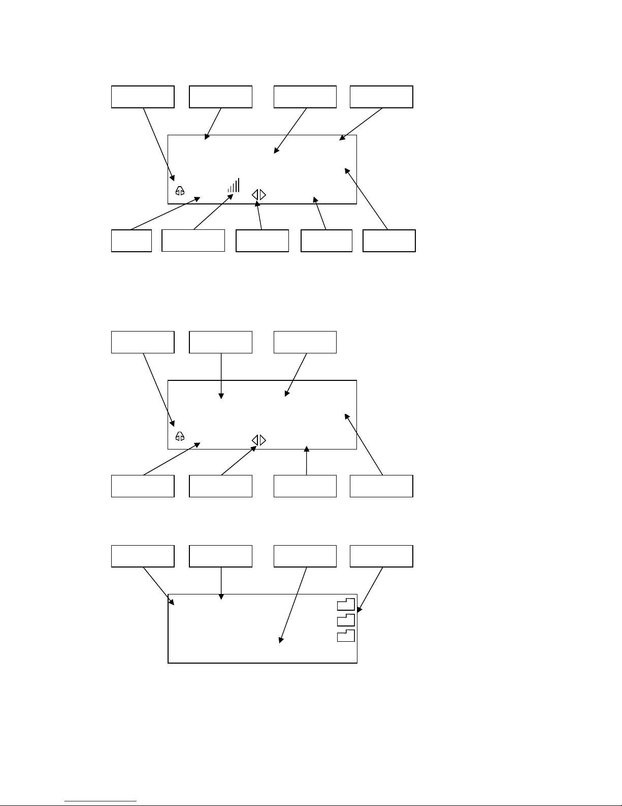
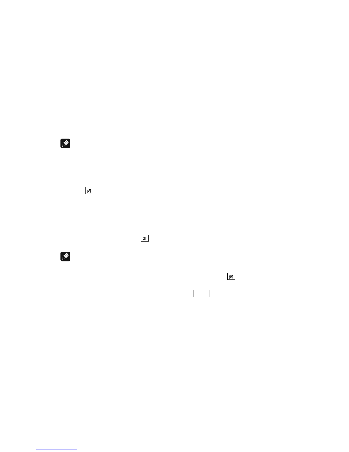
6.2.1.3 FM tuner
6.2.1.4 NET input
· View 1:
· View 2:
Folder icon Marker
Media devices
and internet radio
Marker position
► Internetradio ◄
USB
UPnP Server
NET
BAL Streaming In
Sub 1
-60 dB
Equalizer Input
Balance
(Left/Right)
Volume
Headphones Channel name
Subwoofer /
Multiroom
EQ
WDR 2
FM
BAL FM Radio
99.2
0 MHz Sub 1&2 M
-60 dB
Equalizer Input
Balance
(Left/Right)
Volume
Station frequency Headphones
Subwoofer /
Multiroom
EQ
received signal strength
of FM Station
25
· View 3a (Play from UPnP or USB):
· View 3b (Play from internet radio station):
WDR Event
Track name
► mp3 128 kbps
Play state
Play/Stop/Pause
Data type
Title/Interpreter
Station text
Station name
Data rate
Ludwig van Beethoven
Für Elise
WoO 59
► mp3 00:00:01
Play time Album
Play state
Play/Stop/Pause
Media type
Title Interpreter
26
6.2.2 Volume control
When the DNA is in normal operating mode use the keys up and down
on the front panel to adjust the volume. up to increase, down to decrease
the volume. The volume control of the DNA runs in a range from -80dB
(quiet) to +10dB (very loud) in real 1 dB steps in relation to the level of
the input signal. You can also control the volume with your System Remote Control Harmony One or the software Audionet RCP. Multiroom
volume can only be set with your system remote control Harmony One or
the software Audionet RCP (see section "7.5 - Screen 4" on page 36 and
"8.4.1 - Loudspeaker" on page 54).
6.2.3 Muting
Note
· The muting function is available with the Audionet System Remote
Control Harmony One (see section "7.1 - Key assignment DNA" on
page 33).
· You can also use software Audionet RCP
Press key of the Audionet System Remote Control Harmony One to
mute or un-mute your DNA.
Just as well as the input selection, the DNA uses soft muting, i.e. volume
is stepped down gently to -80 dB, and then the outputs are switched off.
The display informs the user of a muted unit with the text MUTE. Even if
the dim level is set to Off, the text is displayed.
To un-mute the DNA press key again. Here as well, the volume is
stepped up gently to its original level after switching on the outputs.
Note
· While the unit is muted, you may of course select a different input
channel. But the DNA will stay muted until you press the key
again to un-mute and restore the original volume level.
· If you turn up the volume by using the up key or Vol+ , while the
DNA is muted, the muting function will be deactivated and the new
volume level set.
27
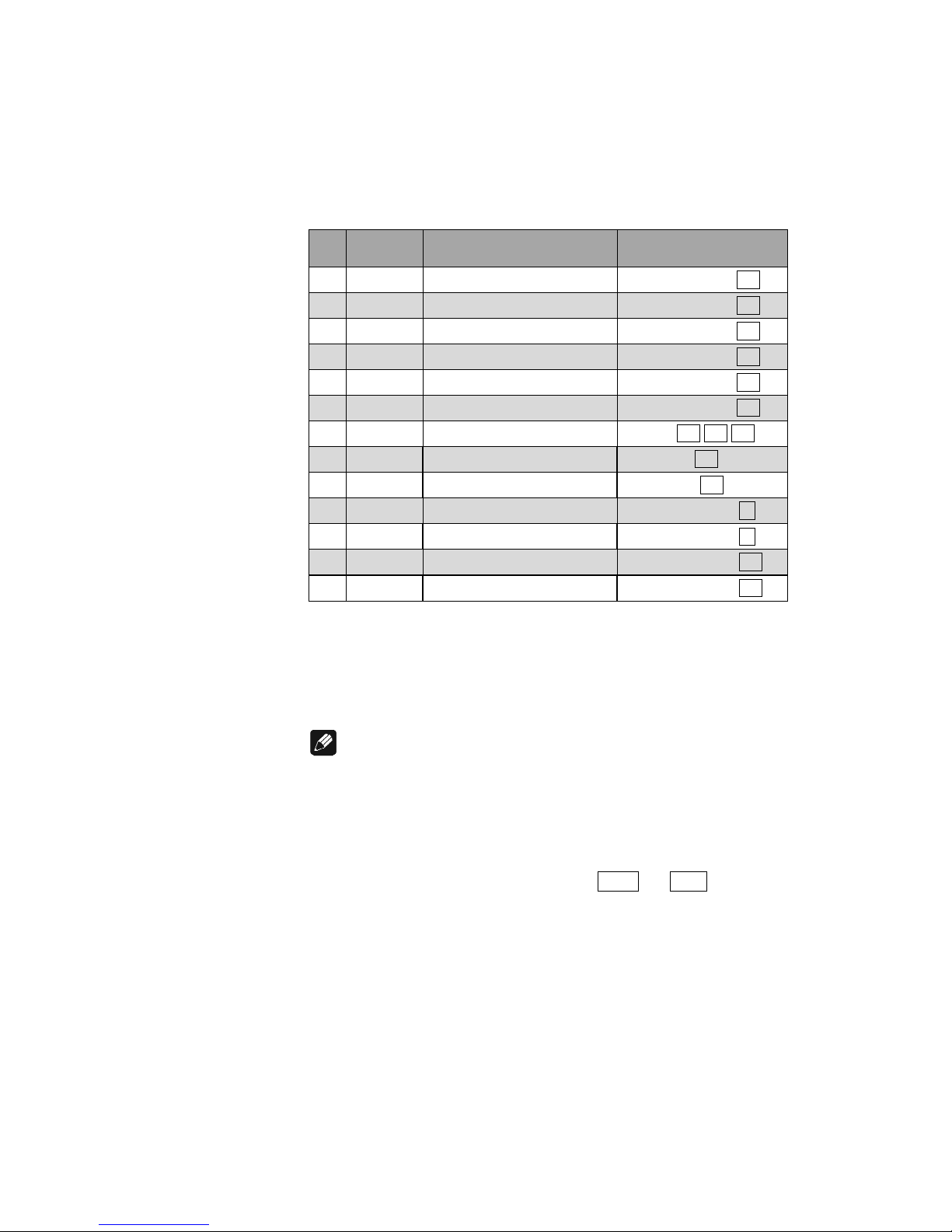
6.2.4 Input selection
Push the set key on the front panel once for less than two seconds to enter
the input selection menu. Then select the desired input channel with the
keys up and down. In the display you see the selected input channel,
channel number and your chosen channel name. Press set to apply the
channel switching. Overview of DNA input channels:
No. Inputs Signal
see 3 - Overview back
panel on page 10
1 D1 Digital (electrical) Digital Inputs IN 1 19
2 D2 Digital (electrical) Digital Inputs IN 2 19
3 D3 Digital (electrical) Digital Inputs IN 3 19
4 D4 Digital (electrical) Digital Inputs IN 4 19
5 D5 Digital (optical) Digital Inputs IN 5 12
6 D6 Digital (optical) Digital Inputs IN 6 12
7 NET Stream, USB, Internet radio Network 20 21 22
8 USB USB Audio In USB Audio 18
9 FM FM Tuner FM Antenna 13
10 AN1 Unbalanced Line Analog Inputs IN 1 4
11 AN2 Unbalanced Line Analog Inputs IN 2 5
12 AN3 Unbalanced Line / Phono Analog Inputs IN 3 24
13 AN4 Balanced Line Analog Inputs IN 4 23
The DNA features a soft input selection. During the switching of inputs,
first the volume is stepped down to –80 dB, followed by switching off the
outputs. Now the input section switches to the new input channel. Afterwards the outputs are switched on again, and finally the volume is
stepped up to its original level.
Note
· Leave the input selection function by holding down the set key
longer than 2 seconds or wait a few seconds.
· Using the Audionet System Remote Control Harmony One, select an
input channel by simply pressing the corresponding key (see section
"7.2 - Screen 1" on page 34, "7.3 - Screen 2"on page 35 and "7.4 Screen 3" on page 35), or use the keys Ch+ and Ch- to switch to
the next or previous input channel without using the Select Input
function.
 Loading...