

Page 1

P. 1
- AUDIOL AB Live AN Split
LIVE AN SPLIT
Professional splitter & mixer
USER MANUAL
Page 2

P. 2
AUDIOLAB Live AN Split -
LIVE AN SPLIT
Professional splitter & mixer - 2 inputs & 6 outputs
Live AN Split is a professional audio solution that
can be used as a splitter or as a mixer. With two
inputs and six outputs, balance and level controls
per channel, and occupying a single rack unit, the
xture is a versatile tool that allows the user to
multiply the signal without losing quality. Live AN
Split also has LED indicators per channel, 4 XLR &
2 1/4" TRS connectors that can be easily switched
between mixer and splitter mode.
Specications
Features
• 1 rack unit
• Splitter / Mixer switch for each mono channel
• 6+2 outputs / splitter mode
• Level/Pan control per channel
• Main input and output level control
• 4 XLR / 2 TRS 1/4" balanced connectors
Audio Inputs
• Connectors: XLR and 1/4" TRS
• Type: RF ltered, servo-balanced input
• Impedance: 50 kOhms balanced, 25 kOhms
unbalanced
• Nominal operating level: -10 dBV to +4 dBu
• Max. input level: +21 dBu balanced and unbal-
anced
• CMRR Typ.: 40 dB, > 55 dB @ 1 kHz
Audio Outputs
• Connectors: XLR and 1/4" TRS
Type: Electronically servo-balanced output
stage
• Impedance: 60 Ohms balanced, 30 Ohms
unbalanced
• Max. output level: +22 dBu balanced and
unbalanced
System specications
• Frequency response: 5 Hz to 200 kHz, +/- 3 dBu
• S/N ratio: >95 dBu, unweighted, 22 Hz to 22 kHz
• THD: <0.002 % typ. @ +4 dBu, 1kHz, gain 1
Control
• Main input level: variable
• Main output level: variable
• Level: variable for each channel
• Balance/pan: placing in the stereo eld
• Main Link: links the main input signal to the
main output
• Split/mix: changeover from split to mix mode
for each channel
Indicators
• Input level (main): 6-digit LED display: -18/12/- 6/0/+12/Clip
• Output level (main): 6-digit LED display: -18/12/- 6/0/+12/Clip
• Input/output level: 6-digit LED display: -18/12/- 6/0/+12/Clip
Physical
• Dimensions: 483x195x44 mm. / 19x7.54x1.7 in.
• Weight: 2.6 Kg. / 5.73 Lbs.
1. OVERVIEW
English version
Page 3
P. 3
- AUDIOL AB Live AN Split
English version
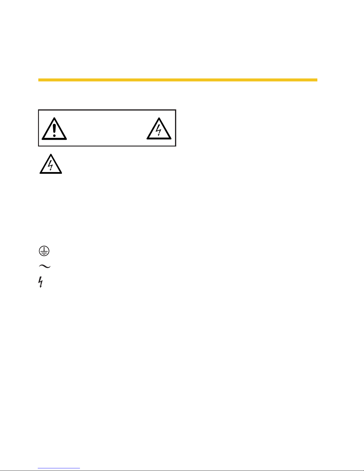
2. SAFETY RELATED SYMBOLS
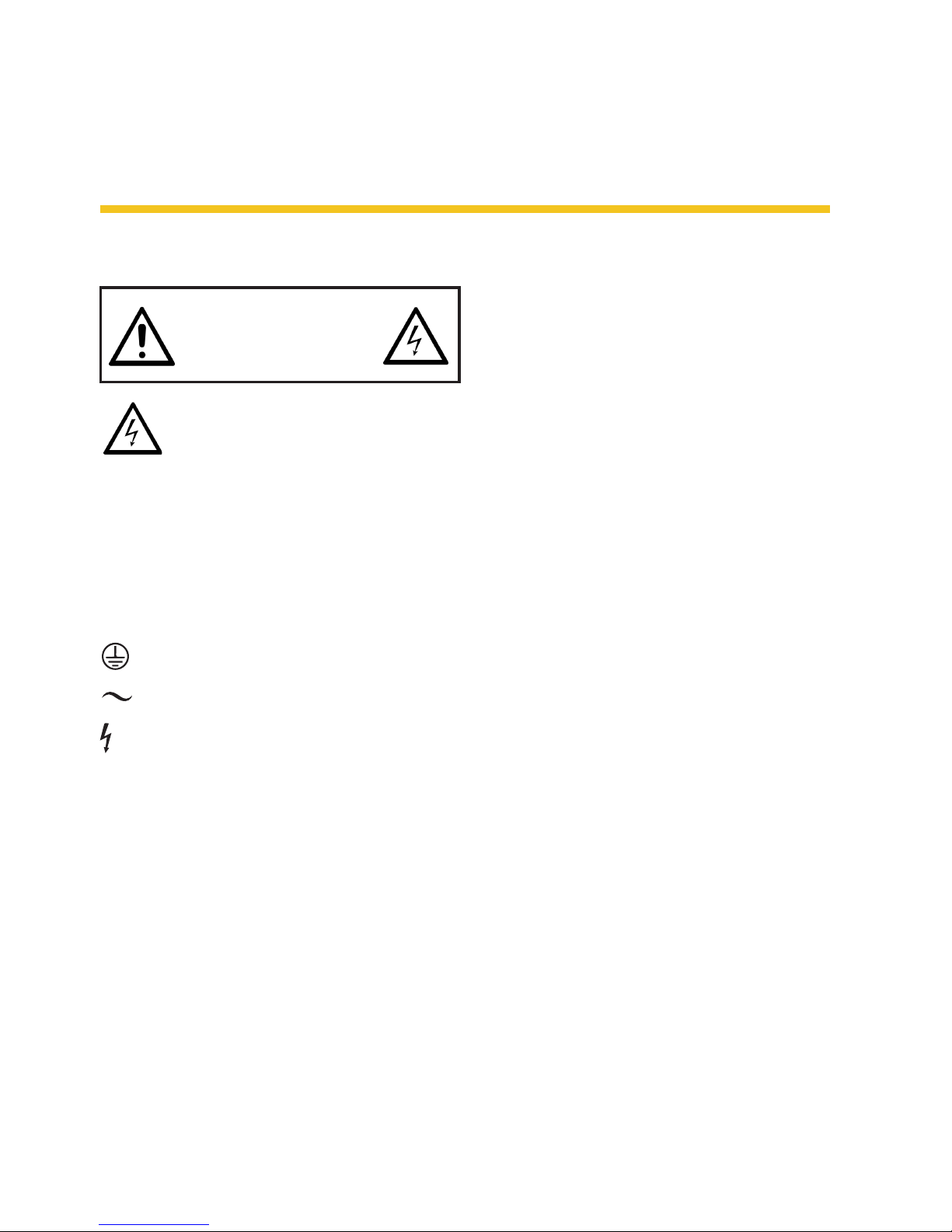
This symbol, wherever used, alerts you
to the presence of un-insulated and
dangerous voltages within the product
enclosure. These are voltages that may be suf-
ecient to constitute the risk of electric shock or
death.
This symbol, wherever used, alerts you to important operating and maintenance instructions.
Please read.
Protective Ground Terminal.
AC mains (Alternating Current)
AC mains (Alternating Current)
ON: Denotes the product is turned on.
OFF: Denotes the product is turned o.
Warning
Describes precautions that should be observed
to prevent the possibility of death or injury to the
use r.
Caution
Describes porecautions that shuld be observed to
prevent damage to the product.
Disposing of this product should not be placed in
municipal waste but rather in a separate collection.
Warning
Power supply
Ensure that the mains source voltage (AC outlet)
matches the voltage rating of the product. Failure to do so could result in damage to the product and possibly the user. Unplug the product
before electrical storms occur and when unused
for long periods of time to reduce the risk of
electric shock or re.
External Connection
Always use proper ready-made insulated mains
cabling (power cord). Failure to do so could
result in shock/death or re. If in doubt, seek
advice from a registered electrician.
Do Not Remove Any Covers
Within the product are areas where high voltages may present. To reduce the risk of electric
shock do not remove any covers unless the AC
mains power cord is removed. Covers should be
removed by qualied service personnel only.
No user serviciable parts inside.
Fuse
To prevent re and damage to the product, use
only the recommended fuse type as indicated in
this manual. Do not short-circuit the fuse holder.
Before replacing the fuse, make sure that the
product is o and disconnected from the AC
outlet.
Protective Ground
Before turning the unit ON, make sure that it is
connected to ground. This is to prevent the risk
of electric shock.
Never cut internal or external Ground wires.
Likewise, never remove Ground wiring from the
RISK OF ELECTRIC SHOCK
DO NOT OPEN.
CAUTION!
Page 4

P. 4
AUDIOLAB Live AN Split -
English version
Protective Ground Terminal.
Operating Conditions
• Always install in accordance with the manufac-
turer's instructions.
• To avoid the risk of electric shock and damage,
do not subject this producto to any liquid/rain
or moisture.
• Do not use this product when in close proximity to water.
• Do not install this product near any direct heat
source.
• Do not block areas of ventilation. Failure to do
so could result in re.
• Keep product away from naked ames.
Important safety instructions
Read these instructions.
Follow all instructions.
Keep these instructions. Do not discard.
Heed all warining.
Only use attachments/accessories specied by
the manunfacturer.
Power Cord and Plug
Do not tamper with the power cord or plug. These
are designed for your safety.
Do not remove Ground connections.
If the plug does not t your AC outlet seek advice
from a qualied electrician.
Protect the power cord and plug from any physical
stress to avoid risk of electric shock.
Do not place heavy objects on the power cord.
This could cause electric shock or re.
Cleaning
When required, either blow o dust from the
product or use a dry cloth.
Do not use any solvents such as Benzol or Alcohol.
For safety, keep product clean and free from dust.
Servicing
Refer all servicing to qualied service personnel
only. Do not perform any servicing other than
those introductions contained within the User's
Manual.
Portable Cart warning
Carts and stands
The component should be used
only with a cart os stand that is
recommended by the manufacturer. A component and cart combination should be moved with care.
Quick stops, excessive force, and uneven surfaces may cause the component and cart combination to overturn.
Page 5
P. 5
- AUDIOL AB Live AN Split
English version
3. CONTROL ELEMENTS
be sent to the main output bus,combined
with the main input signal on condition
that the MAIN LINK is activated, you can get
themixed signal output from the MAIN OUT
sockets. Further, also for the MIXER mode,
you can route the mono channel input signal
to the mono channel output directly.
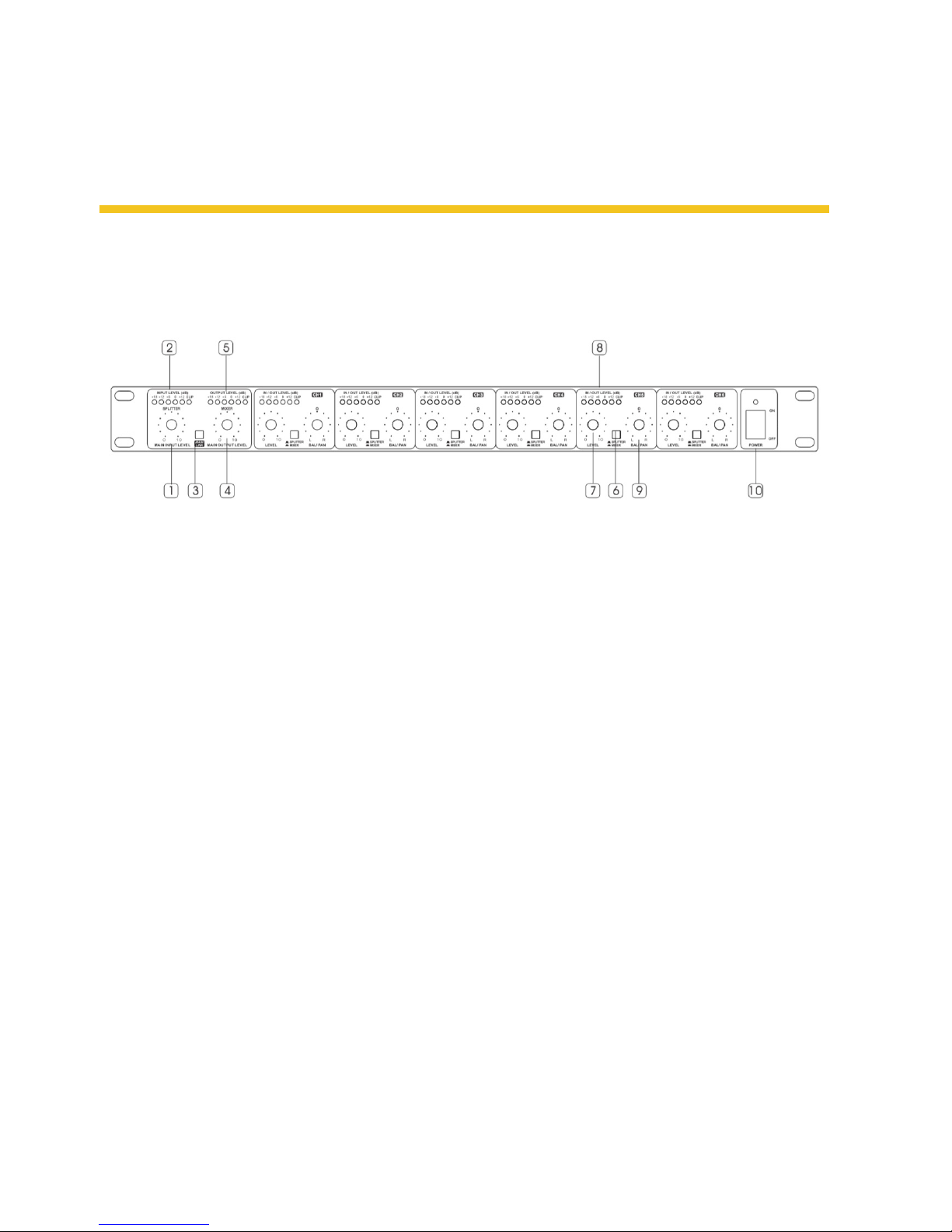
7. LEVEL control for each channel This knob
is used to adjust the level of each mono
channel, and its adjustable range goes from
- to + 10dB, denitely,In SPLITTER mode, this
control is used to determine the output level
of each individual mono channel. While in
MIXER mode, this control can be used to determine how much the mono channel input
signal is sent the main output bus and/or
each individual mono channel output.
8. INPUT/OUTPUT LEVEL meter This 6-dig-
it meter tells you the output level of each
mono channel, while the Clip LED lights up,
please turn down the level control, otherwise, this channel will be distorted.
9. BALANCE/PAN control Generally, the main
section uses the stereo input and output,
while, for each individual channel, mono ap-
plication is congured. So, if the stereo main
signal is split into the mono channel output,
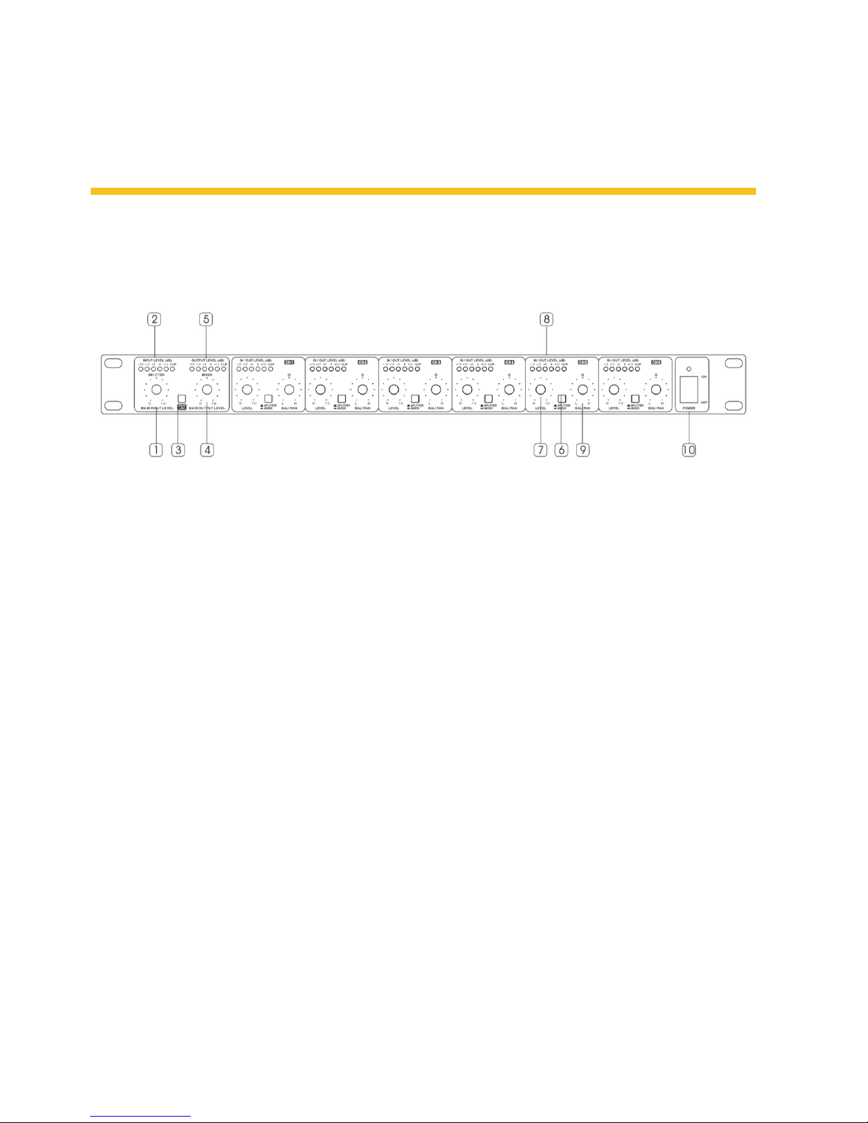
Front panel
1. MAIN INPUT LEVEL control This knob is used
to adjust the level of the main input signal,
and its adjustable range goes from - to + 10dB.
2. INPUT LEVEL meter This 6-digit meter tells
you the level of the main input signal. While
the Clip LED lights up, please turn down the
main input signal, otherwise, the system will
be distorted.
3. MAIN LINK control Use this switch to link the
MAIN IN with the MAIN OUT.
4. MAIN OUT PUT LEVEL control This knob is
used to adjust the level of the main output
signal, and its adjustable range goes from - to
+ 10dB.
5. OUTPUT LEVEL meter This 6-digit meter tells
you the level of the main output signal.While
the Clip LEDl ights up, please turn down the
main signal at either each input stage or themain output stage, otherwise, the system will
be distorted.
6. SPLIT/MIX Use this switch to select the specific operational mode for each individual mono
channel. For SPLITTER mode, please let the
switch released, and the main input signal can
then be split into each mono channel output.
For MIXER mode, please engage this switch,
and now, the mono channel input signal will
Page 6
P. 6
AUDIOLAB Live AN Split -
English version
or the mono input signal is routed to the
stereo main output bus, please use this knob
to determine the proportion between the left
and the right.
10. POWER SWITCH & POWER LED This switch
turns on/o the unit. When the unit is pow-
ered on,the LED will light up.
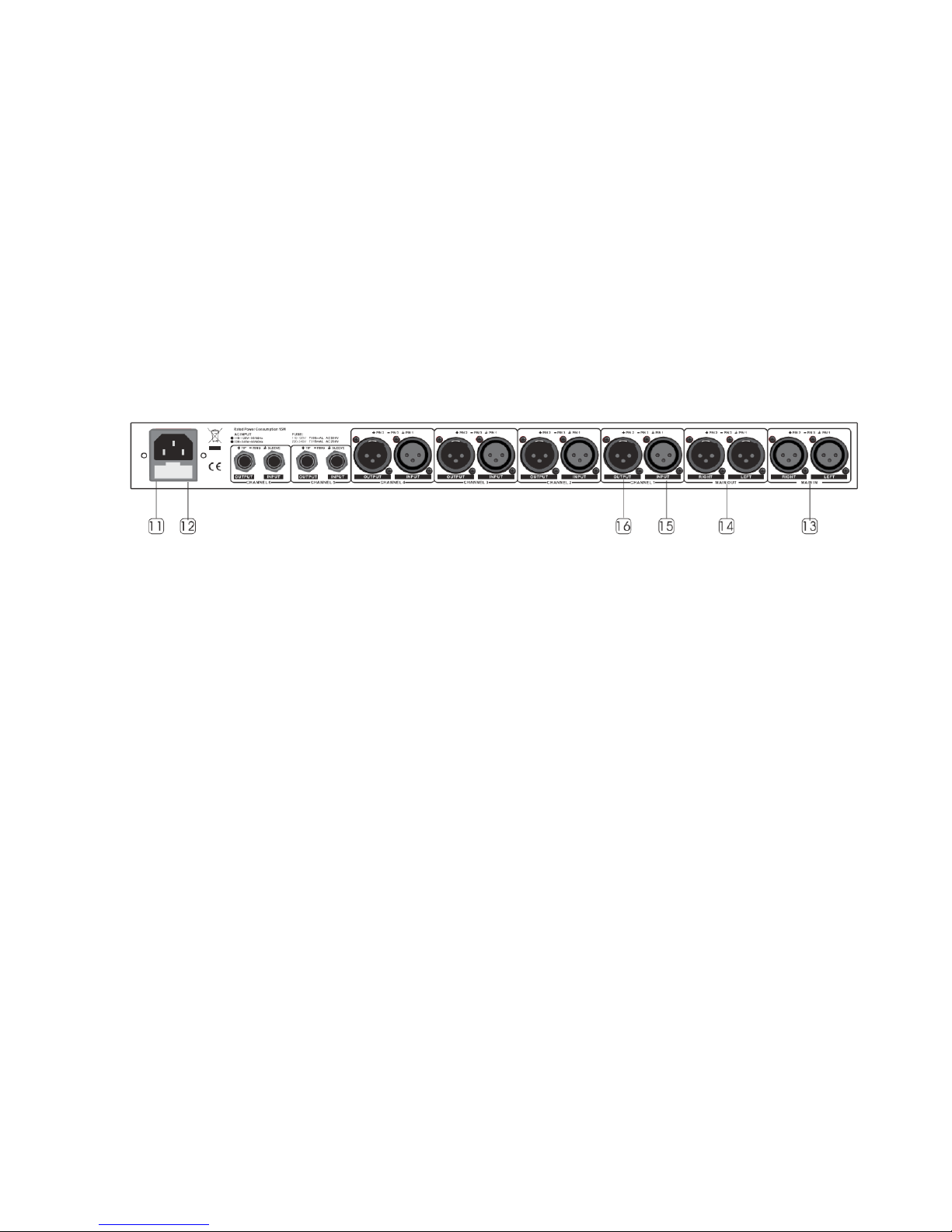
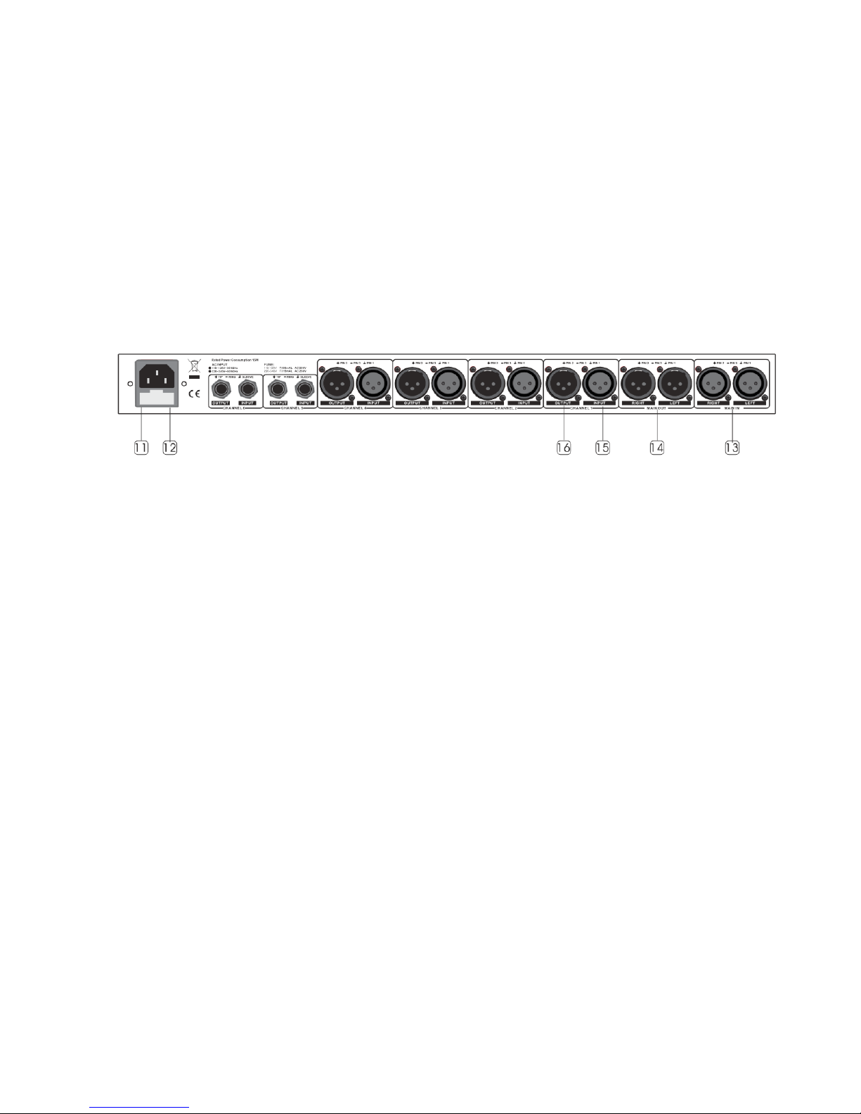
Rear Panel
11. FUSE HOLDER Before you attempt to connect
and operate the unit, please make sure that
your local voltage matches the voltage on the
fuse-holder cover. Caution: The fuse protect-
ing the AC supplies circuits of the unit. The
fuse can only be changed by a qualied techni-
cian, in the event of a foult or changing the
supply voltage. If the fuse continues to blow
after replacing, discontinue use of this unit
before repaired.
12. AC inlet This connector is meant for the
connection of the supplied main cord. Do not
insert power cable into the unit until the voltage has been correctly set. Do not plug power
cable into AC power until voltage has been
correctly set.
13. MAIN INPUTS These two XLR balanced
connectors are used to input the main stereo
signal. In SPLITTER mode, it can be split into
each mono channel output.
14. MAIN OUTPUTS These two XLR balanced con-
nectors are used to output the main stereo
signal. By depressing the MAIN LINK, It can be
linked with the MAIN IN directly.
15. INPUT for the mono channel For Channel
1~4, use the XLR balanced connectors to input the mono signal, while, for Channel 5~6,
please use the TRS type.
16. OUTPUT for the mono channel For Chan-
nel 1~4, use the XLR balanced connectors to
output the mono signal, while, for Channel
5~6, please use the TRS type.
Page 7
P. 7
- AUDIOL AB Live AN Split
English version
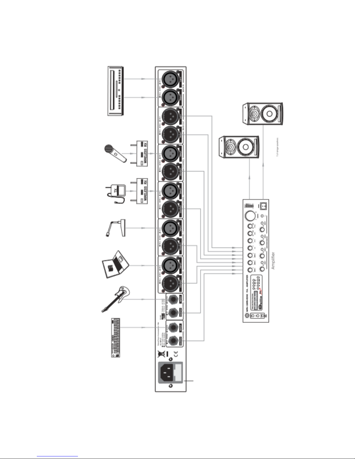
4. APPLICATION
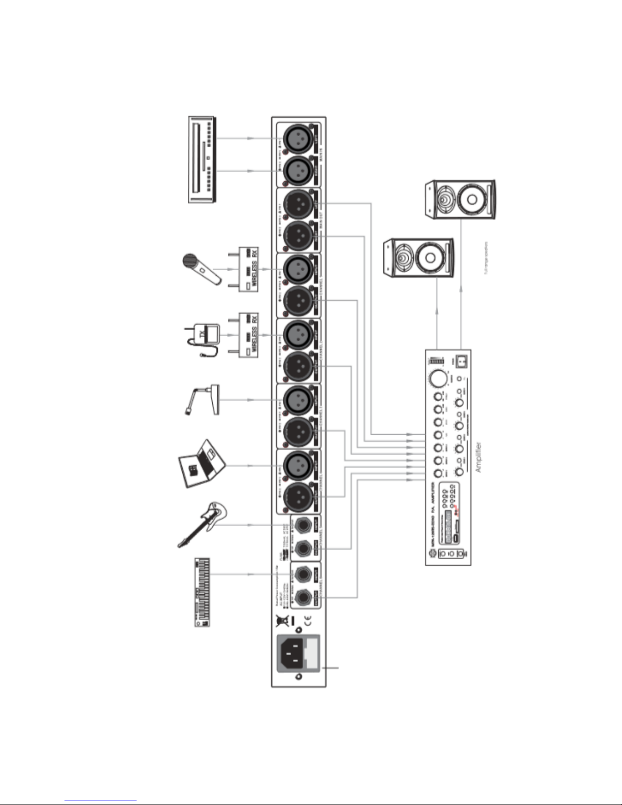
From the panel introduction, you must have
caught a clear answer to "What is it?" in yourmind
as to our Live AN Split, SPLITTER/MIXER, here
after, we will show you the further explanation
on "How to use it?", So that, you can be the real
master of this unit.
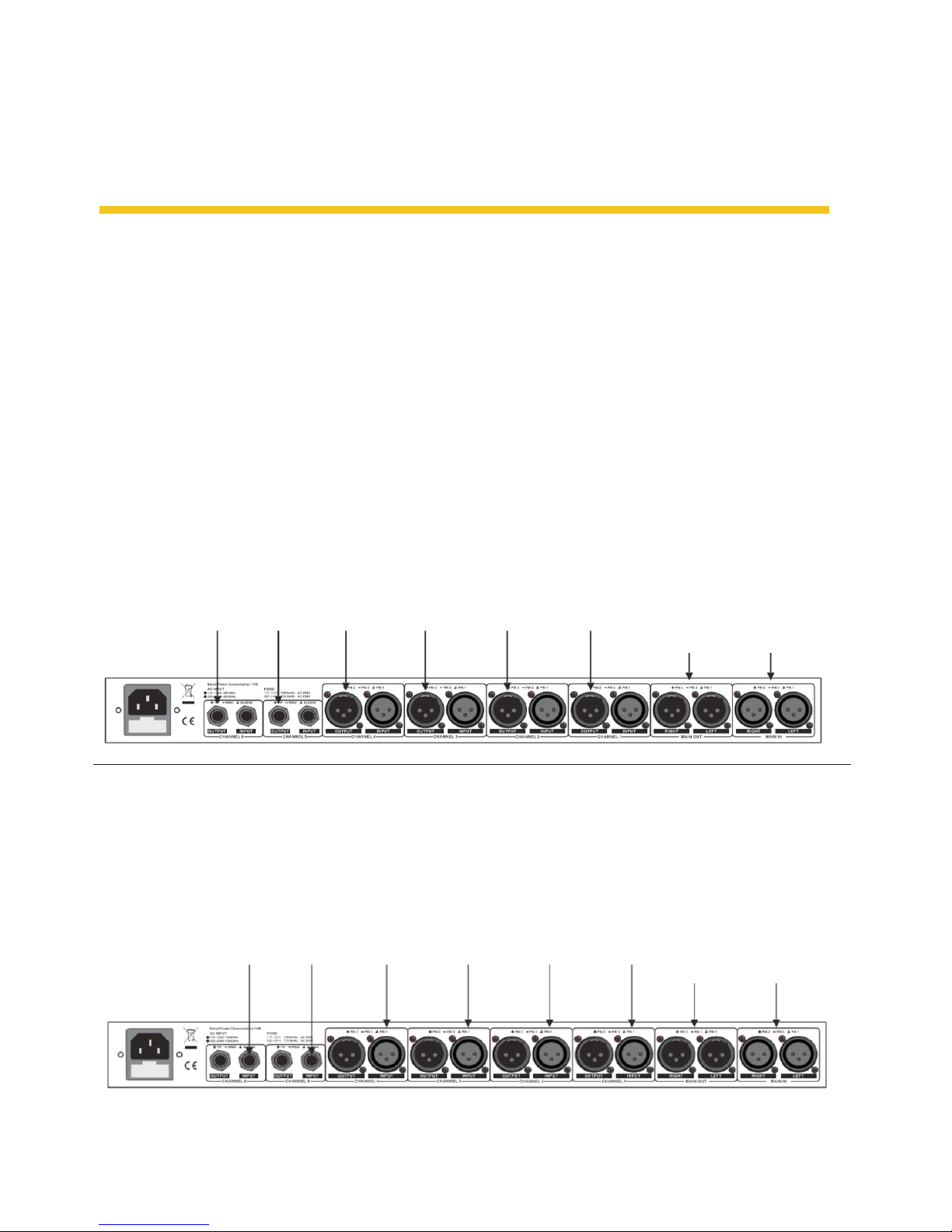
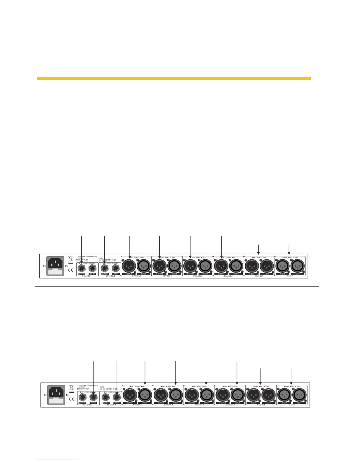
How to use Live AN Split as the splitter
Sometimes,in the large scale PA/sound reinforcement systems, you may be disturbed by this kind
of problems: one pre-send signal needs to be
monitored by several groups, or the main mix output of the console should be transited to several
power ampliers, etc. And now, with your Live AN
Split, you will get the best solution. Connect the
Live AN Split into your systems as the demon-
strated, you can split a specic main input signal
into up to 6 outputs. With the MAIN LINK button
depressed, 2 further outputs are added.
In this application, use the SPLIT/MIX switcht o
select the SPLITTER operational mode for each
mono channel, apply the main signal from the
MAIN IN sockets, and get the 6 outputs from the
mono OUTPUT sockets of each channel. While
the MAIN LINK is engaged, the MAIN OUT will
also be linked with the MAIN IN signal, and two
further outputs are provided.
Output 6 Output 5 Output 4 Output 3 Output 2 Output 1
Two
further
outputs
Main input
signal
Input 6 Input 5 Input 4 Input 3 Input 2 Input 1
Main mixed
signal output
Two further
inputs
How to use Live AN Split as the mixer
This application is widely used for the mixing of
one group main stereo signal with several mono
signals.
In this application, use the SPLIT/MIX switch to
select the MIXER operational mode for each mono
channel,input the signal from the mono INPUT
of each channel, and output the main mixed signal from the MAIN OUT sockets. While theMAIN
LINK is engaged, the MAIN IN will also be linked
with the MAIN OUT signal, and two further input
signals can be mixed with the main output signal.
Page 8
P. 8
AUDIOLAB Live AN Split -
English version
Stereo
Keyboard
Guitar Computer Desktop Paging
Microphone
Wireless
Tie Clip
Wireless
Handheld MIC
DVD Player
Page 9
P. 9
- AUDIOL AB Live AN Split
English version
5. INSTALLATION & CONNECTION
Mains Connection
This is a dual voltage unit. Please ensure that the
Live AN Split is set to the correct supply voltage
before plugging the power cord into the wall
outlet, use the same fuse as marked on the fuse
holder t the AC power connection socket.
Do not insert power cord into the unit until voltage has been correctly set. Do not plug the power
cord into AC power cord into AC power until voltage has been correctly set.
The mains connections of the Live AN Split is
made by using the enclosed mains cord and a
standard IEC receptable. It meets all of the inter-
national safety certication requirements.
Audio Connection
The Live AN Split presents with balanced XLR
connectors and 1/4" TRS phone jack, it can be
inter faced by several ways to support a variety
of applications without any signal loss.
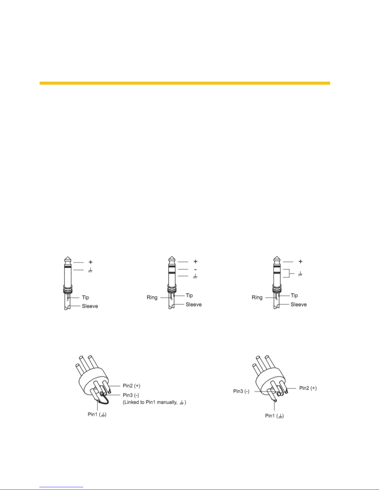
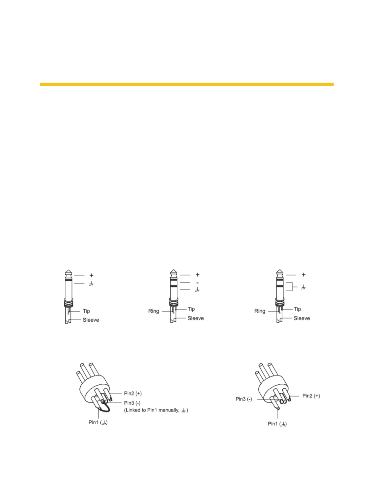
a. Wiring Conguration Eiher the 1/4" TRS
(Tip-Ring-Sleeve) phone jack or the XLR servo
connector can be wired in balanced and unbalanced modes, which will be determined
by the actual application status. Please wire
your systems as the following examples:
• For 1/4" Phone jack
• For XLR connector
TS Type Unbalanced TRS Type Balanced TRS Type Unbalanced
XLR Type Unbalanced XLR Type Balanced
Page 10
P. 1 0
AUDIOLAB Live AN Split -
English version
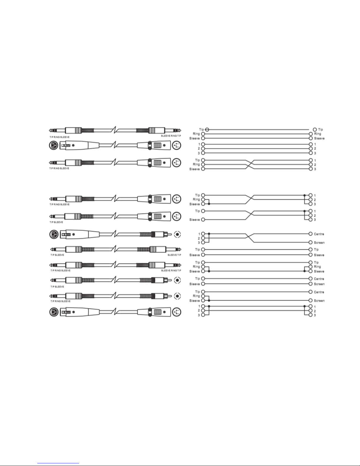
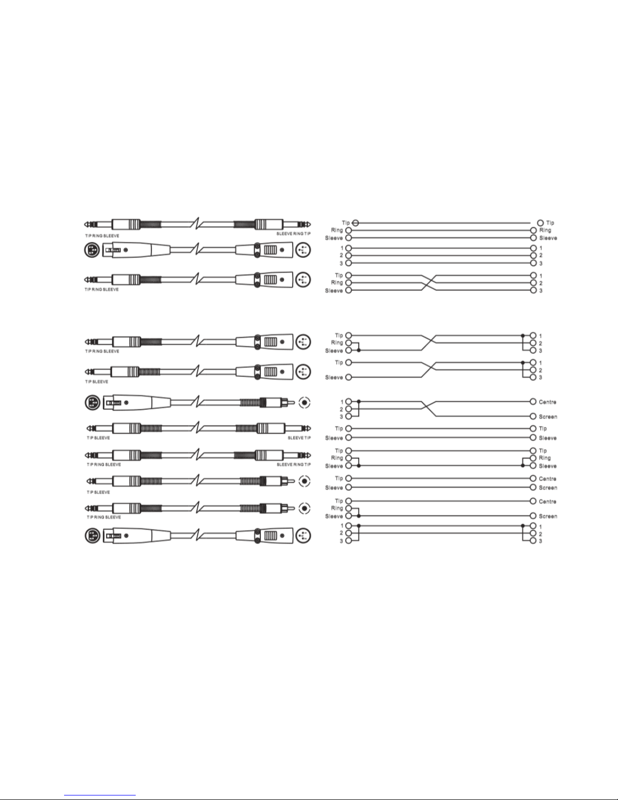
b. In Line Connection For these applications,
the Live AN Split provides XLR connectors and
1/4" TRS phone jack to easily interface with
most professional audio devices. Follow the
conguration examples below for your par-
ticular connection.
• Balanced
• Unbalanced
Rack Mounting
The most secure mounting is on a universal rack
shelf available from various rack manufactures
or your music dealer. The Live AN Split ts into
one standard 19" rack unit of space. Please allow
at least an additional 4" depth for the connectors
on the rear panel. Be sure that there is enough
air space around the unit for sucient ventilation
and please do not place the Live AN Split on high
temperature devices such as power ampliers etc.
to avoid over heating.
Page 11
P. 11
- AUDIOL AB Live AN Split
English version
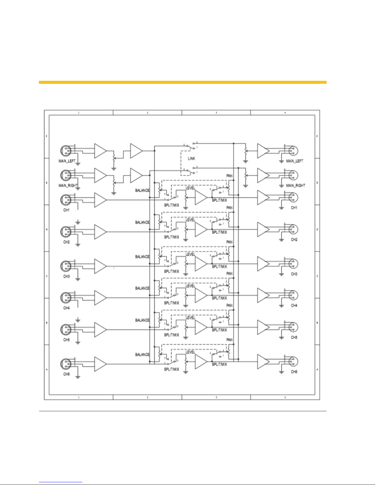
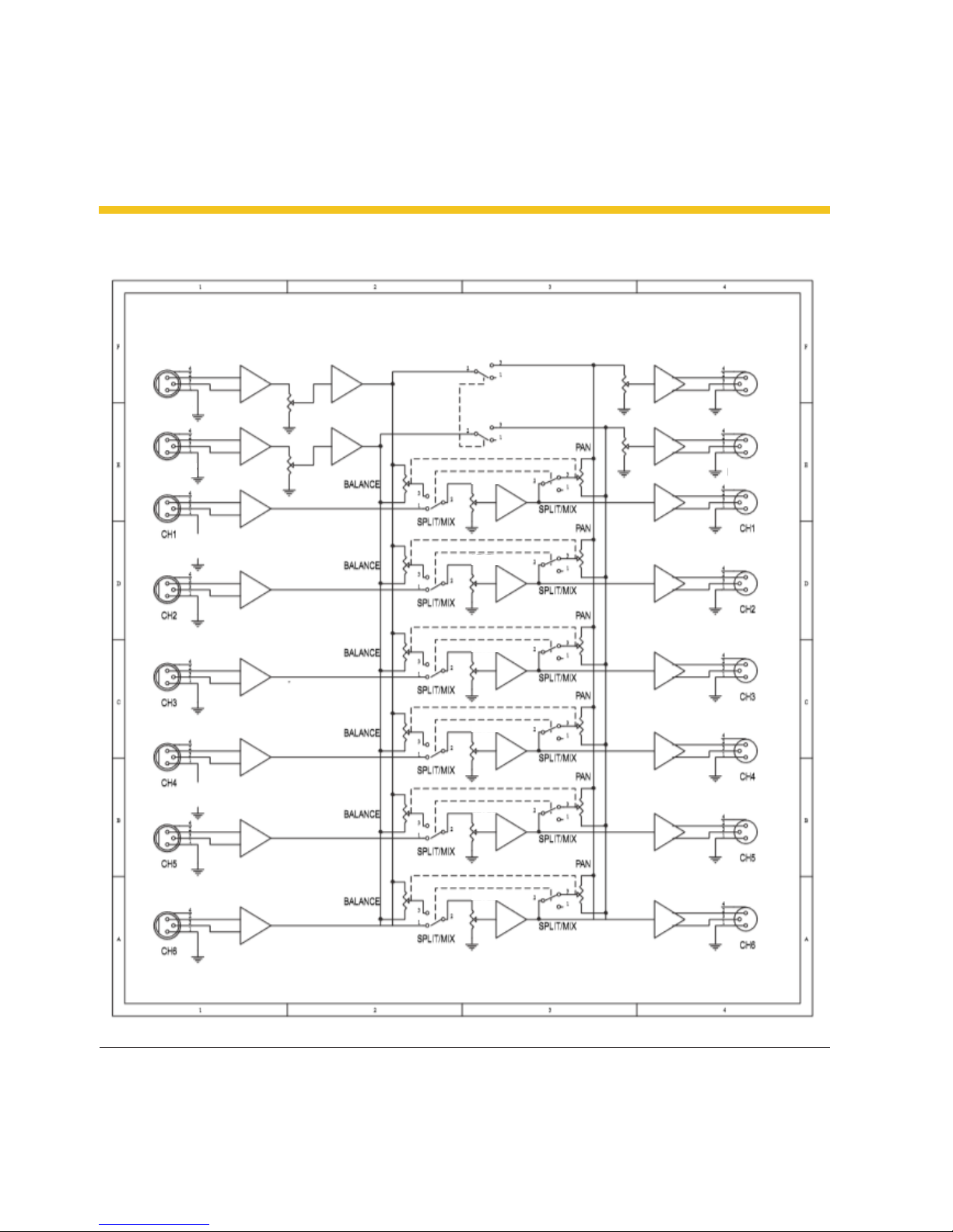
6. BLOCK DIAGRAM
Note: The supplier will not assume responsibility for errors or omissions in the manual. The information
in this manual is subject to change without prior notice.
Page 12

P. 12
AUDIOLAB Live AN Split -
LIVE AN SPLIT
Splitter & mezclador profesional - 2 entradas & 6
salidas
Live AN Split es una solución para aplicaciones de
audio profesional que puede ser utilizado como
splitter o como mezclador. Con dos entradas y
seis salidas, controles de balance y nivel por canal,
y ocupando una sola unidad de rack, el equipo es
una herramienta versátil que permite multiplicar
la señal sin perder calidad. Live AN Split cuenta
además con LEDs indicadores de señal por canal,
4 conectores XLR & 2 conectores 1/4" TRS que
pueden ser fácilmente conmutables entre sus
modos de mezclador y splitter.
Especicaciones
Características
• 1 unidad de rack
• Switch de splitter / mixer por cada canal
• 6+2 salidas / modo de splitter
• Control de nivel/pan por canal
• Control de nivel para la entrada y salida principal
Entradas de audio
• Conectores: XLR & 1/4" TRS
• Tipo: Entradas servo-equilibradas ltradas RF
• Impedancia: 50 kOhms balanceada, 25 kOhms
desbalanceada
• Nivel de operación nominal: -10 dBV a +4 dBu
• Nivel máximo de entrada: +21 dBu balanceado
y desbalanceado
• CMRR: 40 dB > 55 dB @ 1 kHz
Salidas de audio
• Conectores: XLR & 1/4" TRS
• Tipo: Salidas servo-equilibradas ltradas RF
• Impedancia: 60 kOhms balanceada, 30
kOhms desbalanceada
• Nivel máximo de salida: +22 dBu balanceado
y desbalanceado
Especifícaciones
• Respuesta en frecuencia: 5 Hz-200 kHz (+/- 3 dBu)
• Relación de señal-a-ruido: >95 dBu
• THD: <0.002 % @ +4 dBu (1kHz)
Control
• Nivel de entrada principal variable
• Nivel de salida principal variable
• Nivel variable por canal
• Balance/pan variable por canal
• Switch de linkeo principal: Vincula la entrada
principal con la salida principal
• Switch Split/mix: Permite cambiar de split a
mezclador por cada canal
Indicadores
• Nivel de entrada (main): Display LED de
6-digitos: -18/-12/-6/0/+12/Clip
• Nivel de salida (main): Display LED de 6-digitos: -18/-12/-6/0/+12/Clip
• Nivel de entrada & salida: Display LED de
6-digitos: -18/-12/-6/0/+12/Clip
Físico
• Dimensiones: 483x195x44 mm. / 19x7,54x1,7
pulg.
• Peso: 2,6 Kg. / 5,73 Lbs.
1. DESCRIPCIÓN
Versión Español
Page 13
P. 13
- AUDIOL AB Live AN Split
Versión Español
2. SAFETY RELATED SYMBOLS
Este símbolo, siempre que aparezca,
advierte al usuario de la presencia de
voltaje no aislado y peligroso en el inte-
rior de la unidad, con nivel suciente para consti-
tuir un riesgo de descarga eléctrica o muerte.
Este símbolo, siempre que aparezca, advierte al
usuario sobre instrucciones importantes de funcionamiento y mantenimiento.
Lea con atención
Terminal a tierra de protección
Corriente alterna
Corriente alterna
ON: Equipo encendido
OFF: Equipo apagado
Advertencia
Describe las precauciones que deben observarse
para prevenir lesiones o incluso la muerte.
Precaución
El dispositivo no se puede eliminar en un contenedor municipal común. Procure la recogida selectiva del producto según las reglamentaciones
locales correspondientes.
Advertencia
Suministro eléctrico
Verique que el voltaje utilizado coincida con el
requerido por el producto, antes de encenderlo.
No seguir estas instrucciones puede resultar en
descarga eléctrica, riesgo de muerte o incendio.
Desconecte el equipo durante tormentas eléc-
tricas o si no lo va a utilizar durante periodos
largos de tiempo.
Conexión externa
Utilice un cable de suministro eléctrico aislado
adecuadamente. No seguir estas instrucciones
puede resultar en descarga eléctrica, riesgo de
muerte o incendio. Para mayor información,
póngase en contacto con un electricista certi-
cado.
No abra el equipo
La unidad cuenta con zonas de alto voltaje en
su interior. Para reducir el riesgo de descarga
eléctrica, desconecte el equipo del suministro
eléctrico antes de abrirlo. Solo personal calica-
do debe abrir la unidad.
En el interior del equipo no hay piezas que
puedan ser reparadas por el usuario.
Fusible
Utilice únicamente el fusible indicado en el
presente manual para evitar incendios o daños
en la unidad. No haga cortocircuitos con el portafusible. Asegúrese de apagar y desconectar el
equipo antes de sustituir el fusible.
Conexión a tierra
Antes de encender el equipo, verique que
cuente con conexión a tierra para prevenir el
riesgo de descarga eléctrica. Nunca elimine o
deshabilite la conexión a tierra del aparato o del
RIESGO DE DESCARGA
ELÉCTRICA. NO ABRIR.
PELIGRO
Page 14

P. 14
AUDIOLAB Live AN Split -
Versión Español
cable de suministro eléctrico.
Condiciones de funcionamiento
• Procure seguir las instrucciones del distribuidor para realizar la instalación.
• Para evitar el riesgo de descarga eléctrica, no
exponga el equipo a la lluvia, humedad excesiva o líquidos.
• No instale el equipo cerca de fuentes de agua
o fuentes directas de calor.
• Para evitar el riesgo de incendio, no obstruya
las ranuras de ventilación.
• No coloque sobre el equipo ninguna fuente de
llama viva, como velas encendidas.
Advertencias de seguridad
Lea atentamente el presente manual.
Siga todas las instrucciones.
Conserve el manual para futuras referencias.
Respete todas las advertencias.
Utilice solamente los accesorios especicados por
el distribuidor.
Cable de alimentación y enchufe
No altere el enchufe ni el cable de suministro
eléctrico.
No elimine la conexión a tierra.
Si el enchufe suministrado no encaja en la toma,
póngase en contacto con un electricista para sustituir la toma antigua.
Para reducir el riesgo de descarga eléctrica, prote-
ja el cable y el enchufe de pisotones o pinzamientos, en particular cerca de enchufes y en la zona
en que sale del equipo.
No coloque objetos pesados sobre el cable de
suministro eléctrico.
Limpieza
Cuando sea necesario, use una aspiradora para
absorber el polvo o utilice un paño seco.
No utilice solventes como benceno o alcohol.
Por su seguridad mantenga el equipo limpio y
libre de polvo.
Mantenimiento
Póngase en contacto con un profesional calica-
do en caso de necesitar mantenimiento.
Para reducir el riesgo de descarga eléctrica, no
realice ningún tipo de mantenimiento que no
gure en el presente manual.
Traslados
Utilice únicamente la carretilla o
soporte recomendados por su distribuidor para trasladar el equipo.
Desplace la carretilla con cuidado.
Las frenadas bruscas, la fuerza
excesiva y las supercies desparejas pueden
causar vuelcos.
Page 15
P. 15
- AUDIOL AB Live AN Split
Versión Español
3. DESCRIPCIÓN DEL PRODUCTO
Siempre que MAIN LINK esté activado, el
usuario obtendrá la señal de salida mixta
desde los conectores de salida principal.
Además, en el modo mixer, puede enviar
directamente la señal de entrada del canal
mono a la salida del canal mono
7. Control LEVEL para cada canal Utilice la
perilla para regular el nivel de cada canal
mono. Su rango va de -∞ a +10 dB. En modo
splitter, este control se utiliza para determi-
nar el nivel de salida de cada canal mono.
En modo mixer, se utiliza para determinar
cuánto se envía la señal de entrada del canal
mono al bus de salida principal y/o a cada
salida de canal mono individual.
8. Medidor IN/OUT LEVEL El medidor de 6
dígitos indica el nivel de salida de cada canal
mono. Cuando el LED de clip se ilumine, re-
duzca el control del nivel para evitar que se
sature el canal.
9. Control BALANCE/ PAN Generalmente, la
sección principal utiliza la entrada y sali-
da estéreo, mientras que para cada canal
individual se congura la aplicación mono.
Por lo tanto, si la señal estéreo principal se
divide en la salida del canal mono o la señal
de entrada mono se envía al bus de salida
Panel frontal
1. Control MAIN INPUT LEVEL Utilice la perilla
para regular el nivel de la señal de entrada
principal. Su rango va de -∞ a +10 dB.
2. Medidor INPUT LEVEL El medidor de 6 dígitos
indica el nivel de la señal de entrada principal.
Cuando el LED de clip se ilumine, reduzca la
señal de entrada principal para evitar que se
sature el sistema.
3. Control MAIN LINK Utilice el interruptor
para enlazar la entrada principal con la salida
principal.
4. Control MAIN OUTPUT LEVEL Utilice la perilla
para regular el nivel de la señal de salida prin-
cipal. Su rango va de -∞ a +10 dB.
5. Medidor OUTPUT LEVEL El medidor de 6 dígi-
tos indica el nivel de la señal de salida princi-
pal. Cuando el LED de clip se ilumine, reduzca
la señal principal de entrada o de salida para
evitar que se sature el sistema.
6. SPLIT/MIX Utilice este interruptor para seleccionar el modo de funcionamiento de cada
canal mono. Modo splitter: Libere el interruptor, y la señal de entrada principal se dividirá
en salida de canal mono. Modo mixer: Active
el interruptor, y la señal de entrada del canal
mono se enviará al bus de salida principal,
combinada con la señal de entrada principal.
Page 16
P. 1 6
AUDIOLAB Live AN Split -
Versión Español
principal estéreo, utilice esta perilla para determinar la proporción izquierda y derecha.
10. INTERRUPTOR Y LED DE ENCENDIDO/APA-
GADO Utilice el interruptor para encender
y apagar la unidad. Cuando la unidad esté
encendida, se iluminará el LED indicador.
Panel dorsal
11. PORTAFUSIBLES Antes de conectar y utilizar
el equipo, verique que el voltaje de entrada
no sea superior ni inferior al indicado en la
cubierta del portafusibles.Precaución: El fusible protege el circuito de alimentación de CA
de la unidad. Solo un técnico calicado puede
cambiar el fusible en caso de falla o cambio
de rango de voltaje de entrada. Si el fusible
se vuelve a quemar una vez reemplazado,
interrumpa el uso del equipo de inmediato y
proceda con su reparación.
12. Entrada de CA Utilice este conector para el
cable de alimentación principal. No conecte el
cable en la unidad hasta que el voltaje se haya
congurado correctamente. No conecte el
cable a la corriente alterna hasta que el voltaje
se haya congurado correctamente.
13. MAIN IN Estos dos conectores XLR balancea-
dos se utilizan para introducir la señal estéreo
principal. En modo splitter, se puede dividir en
cada salida de canal mono.
14. MAIN OUT Estos dos conectores XLR bal-
anceados se utilizan para emitir la señal
estéreo principal. Si presiona el botón MAIN
LINK, se puede enlazar directamente con la
entrada principal o MAIN IN.
15. INPUT del canal mono Utilice conectores
XLR balanceados para introducir la señal
mono en los canales 1-4 y utilice conectores
TRS en los canales 5-6.
16. OUTPUT del canal mono Utilice conectores
XLR balanceados para emitir la señal mono
en los canales 1-4 y utilice conectores TRS en
los canales 5-6.
Page 17
P. 17
- AUDIOL AB Live AN Split
Versión Español
4. INSTRUCCIONES DE USO
De la introducción del capítulo 3, el usuario debe
haber entendido el concepto de funcionamiento
del LIVE AN SPLIT. En lo sucesivo, se desarrollarán
las instrucciones de uso para que pueda controlar
la unidad en su integridad.
Utilizar LIVE AN SPLIT como splitter
Eventualmente, en las aplicaciones PA de gran
escala o en los sistemas de sonido, el usuario deberá enfrentarse a los siguientes problemas: una
señal de envío debe ser monitoreada por varios
grupos o la salida mixta principal de la consola
debe ser transitada a varios amplicadores de
potencia (entre otros). Ahora, gracias a su LIVE AN
SPLIT obtendrá la mejor solución.
Conecte el LIVE AN SPLIT en su sistema, como se
ilustra debajo. El usuario podrá dividir una señal
de entrada especíca en hasta seis salidas. Si
presiona el botón MAIN LINK, se añadirán dos
salidas más.
Bajo este modo, utilice el interruptor SPLIT/
MIX para seleccionar el modo splitter para cada
canal mono. Aplique la señal principal de los
conectores MAIN IN y obtenga las seis salidas
de los conectores de salida mono de cada canal.
Mientras el interruptor MAIN LINK esté activa-
do, la perilla MAIN OUT se enlazará con la señal
MAIN IN y se añadirán dos salidas más.
Salida 6 Salida 5 Salida 4 Salida 3 Salida 2 Salida 1
Dos
salidas
adicionales
Señal de
entrada
principal
Entrada 6 Entrada 5 Entrada 4 Entrada 3 Entrada 2 Entrada 1
Salida de
señal mixta
principal
Dos entradas
adicionales
Utilizar LIVE AN SPLIT como mixer
En esta aplicación es de las más populares para
mezclar la señal estéreo principal de un grupo con
varias señales mono. En este uso, utilice el interruptor SPLIT/MIX para seleccionar el modo mixer
para cada canal mono. Introduzca la señal de la
entrada mono de cada canal y emita la señal
mixta principal desde los conectores MAIN OUT.
Mientras el interruptor MAIN LINK esté activa-
do, la perilla MAIN OUT se enlazará con la señal
MAIN OUT y dos señales de entrada más se
mezclarán con la señal de salida principal.
Page 18
P. 18
AUDIOLAB Live AN Split -
Versión Español
Tec lado
estéreo
Guitarra Computadora Micrófono de
escritorio
Clip sujetador
inalámbrico
Micrófono de
mano inalámbrico
Reproductor DVD
Page 19
P. 1 9
- AUDIOL AB Live AN Split
Versión Español
5. INSTALACIÓN Y CONEXIÓN
Conexión eléctrica
LIVE AN SPLIT cuenta con voltaje doble. Antes de
utilizar el equipo, verique que el voltaje de en-
trada no sea superior ni inferior al indicado en las
especicaciones técnicas. Utilice el fusible correc-
to, indicado en el portafusibles, en el enchufe de
alimentación.
No conecte el cable en la unidad hasta que el
voltaje se haya congurado correctamente. No
conecte el cable a la corriente alterna hasta que el
voltaje se haya congurado correctamente.
La conexión eléctrica del LIVE AN SPLIT se lleva a
cabo utilizando el cable de alimentación incluido
y un receptáculo IEC estándar. Cumple con todos
los requisitos internacionales de certicación de
seguridad.
Conexión de audio
LIVE AN SPLIT incorpora conectores XLR bal-
anceados y conector de teléfono TRS de 1/4".
Admite diversos tipos de conexiones sin pérdida
de señal.
a. Conguración de los cables Tanto el conec-
tor de teléfono TRS de 1/4" como el servo
conector XLR pueden cablearse en modo
balanceado o desbalanceado, los cuales
serán determinados por el estado de aplicación actual. Para cablear el equipo, sigas
las siguientes instrucciones:
• Conector de 1/4"
• Conector XLR
TS desbalanceado TRS balanceado TRS desbalanceado
XLR desbalanceado XLR balanceado
Page 20
P. 2 0
AUDIOLAB Live AN Split -
Versión Español
b. Conexión LIVE AN SPLIT cuenta con conec-
tores XLR y conector de teléfono TRS de 1/4"
que facilitan la interacción con la gran mayoría
de los dispositivos de audio profesional. Para
conectar su equipo, siga los ejemplos de con-
guración descritos a continuación:
• Balanceado
• Desbalanceado
Montaje en estantería
Para garantizar un montaje seguro, procure utilizar una estantería o rack universal. Póngase en
contacto con su proveedor o
un distribuidor de música para conseguirla. LIVE
AN SPLIT cabe en una unidad de rack de 19" es-
tándar. Procure dejar al menos 4" adicionales de
profundidad para los conectores del panel dorsal.
Asegúrese de instalar el equipo en un ambiente
con buena ventilación y circulación de aire. No
coloque el equipo dispositivos o supercies con
alta temperatura, como amplicadores, para
evitar el sobrecalentamiento.
Page 21
P. 2 1
- AUDIOL AB Live AN Split
Versión Español
6. DIAGRAMA DE BLOQUES
Main
izquierda
Main
izquierda
Main
derecha
Main
derecha
Enlace
Nivel
Nivel
Nivel
Nivel
Nivel
Nivel
Observación: El proveedor no asumirá responsabilidad por los errores u omisiones del manual.
La información de este manual está sujeta a cambios sin previo aviso.
Page 22
P. 2 2
AUDIOLAB Live AN Split -
audiolab.amproweb.com
 Loading...