

Page 1

USER MANUAL / MANUAL DE USUARIO
PLEASE READ THE INSTRUCTIONS CAREFULLY BEFORE USE
POR FAVOR LEA CUIDADOSAMENTE LAS INSTRUCCIONES ANTES DE USAR
Page 2

Overview
DA-2500 II is a professional power amplier with a maximum
output power of 2 x 1300W @ 8-ohm / 2 x 2500W @ 4-ohm /
2 x 4800W @ 2-ohm and a maximum bridged output power
of 9000W (RMS) @ 4-ohm. The unit oers comprehensive
protection circuits for output current, DC, high temperature,
very high frequency (VHF), short circuit, open load, main fuse
protection and soft start. All channels are bridgeable with
automatic -6dB summing compensation. DA-2500 II comes
with guaranteed high eciency, sonic transparency and has
proven its durability in extreme touring conditions.
Specications
Output
Rated output power (8-Ohm): 2 x 1300W
Rated output power (4-Ohm): 2 x 2500W
Rated output power (2-Ohm): 2 x 4800W
Rated output power (Bridge @ 16-Ohm): 2600W
Rated output power (Bridge @ 8-Ohm): 4600W
Rated output power (Bridge @ 4-Ohm): 9000W
Performance
Input Impedance: 20K ohm
Frequency Response: 2.3Hz~56KHz
THD: <0.05%
Crosstalk (at 1Khz): > 70 dB
Signal to noise ratio: >112dBA
CMR: 50 dB
Protections: Excessive output current, Full short-circuit,
Open-circuit, Thermal, Soft-Start, DC voltage, very high
frequency (VHF) & mains fuse protection
Voltage Peak Limiter: Selectable per channel with Hard/Soft
limiter mode
Amplier gain selectable: 23,26, 29, 32, 35 (default), 38, 41 & 44 dB
Connectors & backpanel controls
2 balanced female XLR-3
2 speakon speaker outputs
Input sensitivity selector: 0.77V / 1.0V / 1.4V
Mode selector: Parallel, Stereo & Bridge
Ground: Lift & Gnd
Resumen
DA-2500 II es un amplicador de potencia profesional con
una salida máxima de 2 x 1300W @ 8-ohm / 2 x 2500W @
4-ohm / 2 x 4800W @ 2-ohm y una potencia puente máxima
de 9000W (RMS) @ 4-ohm. La unidad ofrece circuitos de
protección: corriente de salida, DC, altas temperaturas,
muy altas frecuencias (VHF), corto circuito, carga abierta,
protección de fusible principal y de arranque suave. Todos
los canales son puenteables con una compensación de -6dB.
DA-2500 II garantiza alta delidad, transparencia sonóra y ha
probado su durabilidad en las condiciones más extremas.
Especicaciones
Salida
Potencia nominal (8-Ohm): 2 x 1300W
Potencia nominal (4-Ohm): 2 x 2500W
Potencia nominal (2-Ohm): 2 x 4800W
Potencia nominal (Puente @ 16-Ohm): 2600W
Potencia nominal (Puente @ 8-Ohm): 4600W
Potencia nominal (Puente @ 4-Ohm): 9000W
Rendimiento
Impedancia de entrada: 20K ohm
Respuesta en frecuencia: 2.3Hz~56KHz
THD: <0.05%
Crosstalk (at 1Khz): > 70 dB
Relación de señal-a-ruido: >112dBA
CMR: 50 dB
Protectiones: Corriente de salida, corto circuito, circuito
abierto, térmica, arranque suave, voltaje DC, muy altas
frecuencias (VHF) & protección de fusible principal.
Limitador de voltaje pico: Seleccionable por canal con modos
de limitador hard/soft.
Ganancia de amplicador seleccionable:: 23,26, 29, 32, 35 (por
defecto), 38, 41 & 44 dB
Conectores & controles del panel trasero
2 XLR-3 hembras balanceados
2 salidas de parlante speakon
Selector de sensibilidad de entrada: 0.77V / 1.0V / 1.4V
Selector de modo: Paralelo, Estereo & Puente
Page 3

Front panel / Panel frontal
El panel frontal del amplicador cuenta con indicadores en caso
de funcionamiento defectuoso, interruptores de alimentación y
de accionamiento remoto y una cubierta de ltro desmontable
para protección contra polvo. Los dos potenciómetros de
nivel ubicados detrás de la cubierta del ltro proveen una
atenuación individual para los dos canales del amplicador. El
margen es de 0 dB a menos innito. La posición “12 en punto”
indica una atenuación de -10 dB.
Para desmontar la cubierta del ltro de protección contra
polvo, aoje los tornillos ubicados en el extremo izquierdo.
Esto permitirá extraer los ltros de polvo para su limpieza y
también acceder a la atenuación de canales.
NOTA: El amplicador no debe ser utilizado si el ltro de
protección contra polvo no se encuentra colocado de manera
adecuada
Interruptor de encendido y apagado
El interruptor de encendido y apagado se ubica en el costado
derecho de la unidad. Para encender o apagar la unidad,
presione la parte superior o inferior, respectivamente, de
esta tecla. Antes de encender el amplicador, verique todas
las conexiones y reduzca los controles de nivel. Por lo general,
se produce un silenciamiento momentáneo al encender o
apagar el amplicador.
Precaución: procure siempre encender el amplicador de
potencia en última instancia, luego de haber encendido los
restantes equipos conectados. Por el contrario, procure
siempre apagar el amplicador en primer lugar y luego los
demás equipos.
The amplier’s front panel presents the performance and
fault condition indicators, power and remote switches, and a
removable dust-lter cover. Two level potentiometers located
behind the cover provide individual attenuation for the two
amplier channels. Range is 0 dB to - innity. The 12 o’clock
position indicates -10 dB attenuation.
To remove the dust-lter cover, loosen the thumbscrew at the
far left. This allows removal of the dust-lters for cleaning, and
provides access to channel attenuation.
NOTE: Never operate the amplier without the dust-lters
in place.
Power on/o switch
The power on/o switch is located on the right side.
To turn the unit ON or OFF, press the upper or lower portion
of this button. Before turning on the amplier, check all the
connections and turn down the level controls. A momentary
muting is normal when turning the amplier on or o.
Caution: Always turn on your power amplier last, after all
your other connected equipment, and always turn o your
power amplier before your other connected equipment.
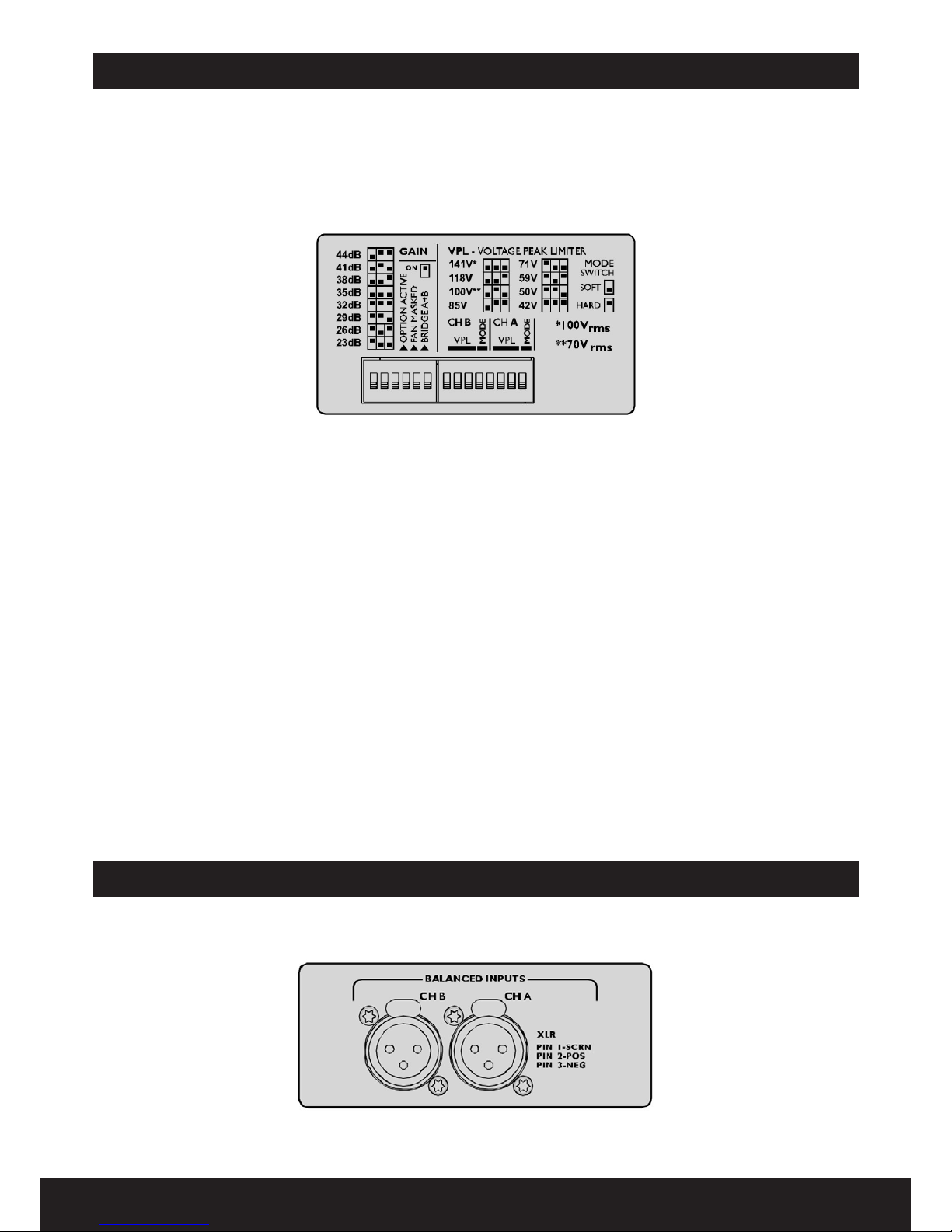
Dip Switch: Dip-switches to control Gain, Option active,
Bridge A+B, VPL & Mode
Physical
Cooling: Two Front-to-back fans, temperature controlled speed.
Weight: 12 Kg. / 26.4 lbs.
Dimension: 483 x 343 x 88 mm. / 19x13.5x3.5 in
“All the specications are subject to change without notice.
Tierra: Lift & Gnd
Dip Switch: Dip-switch para controlar ganancia, opciones
activas, puente A+B, VPL & modo
Físico
Refrigeración: Dos ventiladores con velocidad controlable.
Peso: 12 Kg. / 26.4 lbs.
Dimensiones: 483 x 343 x 88 mm. / 19x13.5x3.5 in.
“Todas las especicaciones anteriores están sujetas a
modicación sin previo aviso.
Page 4

Front-panel LED’s
The front-panel LED area includes the following indicators
per channel:
• VHF - Very High Frequency protection active (output
muted) (Yellow constant)
• TEMP - Temperature warning (Yellow ashing)
• TEMP - Temperature mute (Yellow constant)
• CPL - Current Peak Limiter (CPL) active (Red ashing)
• CPL - (Red constant with output muted): Low impedance
/ Short circuit detection fault
• VPL - Voltage Peak Limiter (VPL) active
• SIG - Signal levels - 40 dB (Sig) to -4dB
• HI-IMP - High-impedance / open load detected (Green)
NOTE: When no VPL, CPL or PAL indicators are illuminated,
and the VPL DIP-switch is set to maximum at the specifed
nominal load, the amplier channel is able to deliver
maximum rated output power
Front panel global LED eld
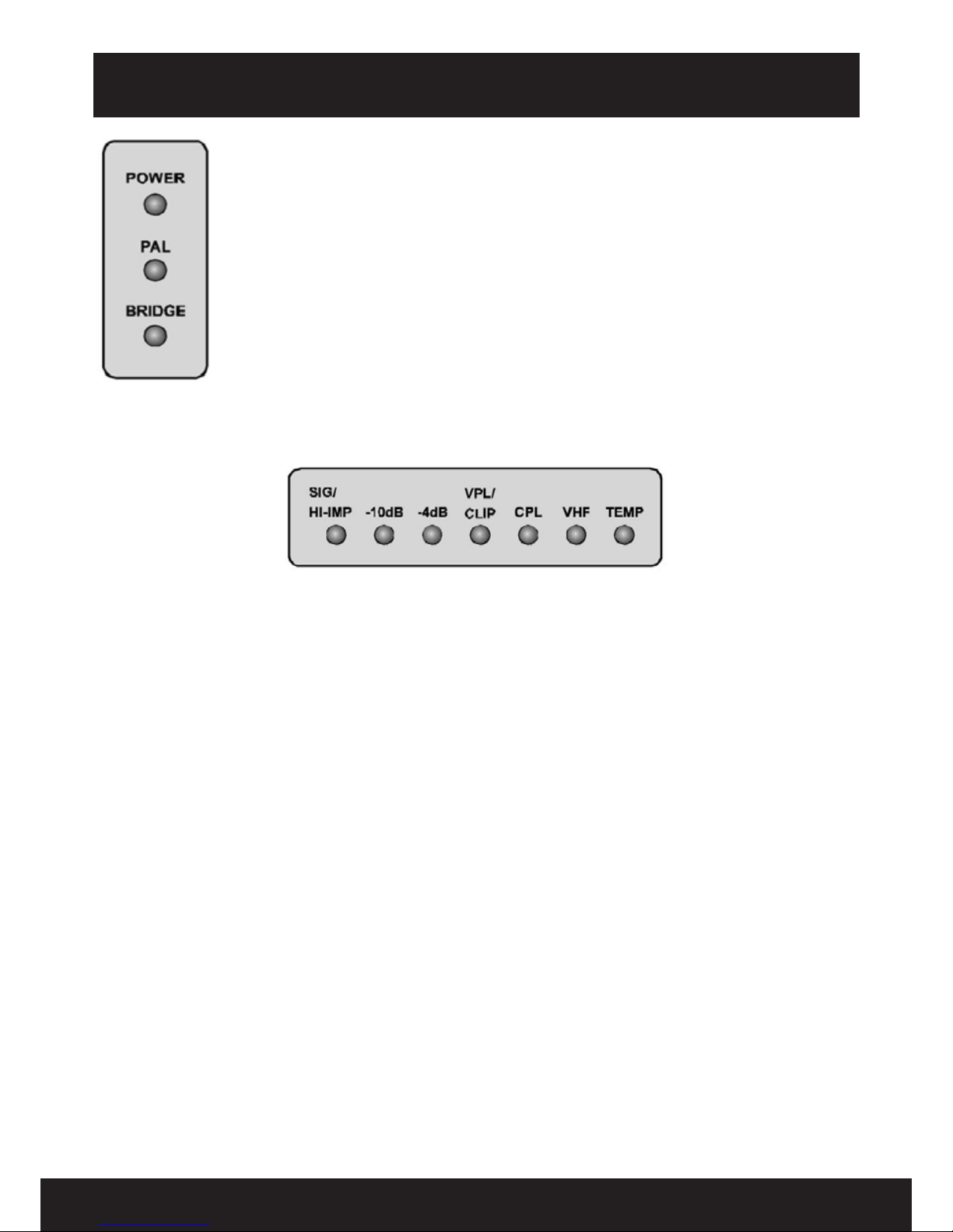
POWER: Power on (Green)
PAL: Power Average Limited (Red)
BRIDGE: Bridge mode operation (Yellow)
Indicadores LED del panel frontal
Los indicadores LED del panel frontal por canal son los
siguientes:
• VHF - Protección de frecuencias muy altas activa
(Salida silenciada) (Amarillo constante)
• TEMP - Alerta de temperatura (Amarillo parpadeando)
• TEMP - Silenciado por temperatura (Amarillo
constante)
• CPL - Limitador de pico de corriente (CPL) activo (Rojo
parpadeando)
• CPL - (Rojo constante con la salida silenciado): Baja
impedancia / Corto circuito detectado
• VPL - Limitador de Voltaje Pico (VPL) activo
• SIG - Niveles de señal - 40 dB (Sig) a -4dB
• HI-IMP - Alta impedancia / Carga abierta detectada
(Verde)
NOTE: Cuando no están iluminados los indicadores
de VPL, CPL o PAL, y el VPL DIP-switch está congurado
en máximo a la carga nominal especicada, el canal de
amplicación entrega su máxima potencia nominal.
Campo LED del panel frontal
POWER: Amplicador encendido.
Color:Verde
PAL: Limitador de potencia media activado.
Color: Rojo
BRIDGE: Operación en modo puente.
Color: Amarillo
Back panel / Panel trasero
MAIN INPUT 115V OR 230V
OPERATION (NOT SELECTABLE)
/ ENTRADA DE POTENCIA DE RED:
115V O 230V (NO AJUSTABLE)
DIP-SWITCHES FOR ADJUSTING
KEY FEATURES (SEE BELOW)
/ INTERRUPTORES DIP PARA
AJUSTAR PARAMETROS CLAVE
(VEASE ABAJO)
XLR CONNECTORS FOR
INPUTS AND LOOP THRU
/ CONECTORES XLR PARA
ENTRADAS Y SALIDAS “LOOP
THRU”
2 CHANNEL VERSION SHOWN
WITH NEUTRIK SPEAKON OUTPUT
CONNECTORS
/ MODELO DE 2 CANALES CON
CONECTORES OUT NEUTRIK
SPEAKON
Page 5
Operation and performance / Operación y funcionamiento
Conguration section
NOTE: Two-channel versions have VPL and Bridge Mode
switches for channels A and B only. All models have dierent
VPL values. Functions are otherwise identical.
The DIP-switch features
The following featuresmay be adjusted using the DIP-switches
on the rear panel of the amplier.
• Gain - Globally set for all channels, from +23 dB to +44
dB in 3 dB steps.
• Option active - Not currently implemented.
• Fan Masked - When on, engages pairs into bridged
mode operation (Automatic -6 dB gain compensation).
• VPL - Voltage Peak Limiter adjustment is provided for 8
individual levels. Select the setting most appropiate for
connected speakers.
• Mode - Select VPL mode to either Hard of Soft operation.
For channels driving sub-woofers and low-frequency
drivers, it is recommended to use the Hard setting for
optimal operation. For mid- and high- frequency drivers,
always select Soft.
Conguration section
NOTA: Los amplicadores de dos canales tienen interruptores VPL y
de Modo Puente para los canales A y B solamente. Todos los modelos
poseen diferentes valores de VPL. Las demás funciones son idénticas.
Características del interruptor DIP
Las siguientes características podrán ajustarse mediante los
interruptores DIP ubicados en el panel trasero del amplicador.
• Ganancia - Congurada para todos los canales. Valor:
desde +23 dB a +44 dB en pasos de 3 dB.
• Opción activa - No se encuentra implementada actualmente.
• Ventilador - Cuando se enciende la unidad, el ventilador
inteligente se activa. La velocidad disminuye ante la falta
de señal.
• VPL - Se proporciona un ajuste del Limitador de
voltaje pico para 8 niveles individuales. Seleccione
la conguración que resulte más adecuada para los
altavoces conectados.
• Modo - Seleccione el modo VPL para un funcionamiento
Hard o Soft. En el caso de canales con subwoofer y
drivers de baja frecuencia, se recomienda utilizar la
conguración Hard para obtener un funcionamiento
óptimo. En el caso de drivers de frecuencias medias y
altas, procure seleccionar el modo Soft.
Balanced input connections
AUDIO INPUTS AND LOOP-THRU CONNECTORS, TWO-CHANNEL MODELS
/ CONECTORES DE ENTRADA DE AUDIO Y SALIDA “LOOP THRU”. MODELOS DE 2 CANALES
Conexiones de entrada balanceada
In and Out audio connections / Conexiones de entrada y salida de audio.
Page 6
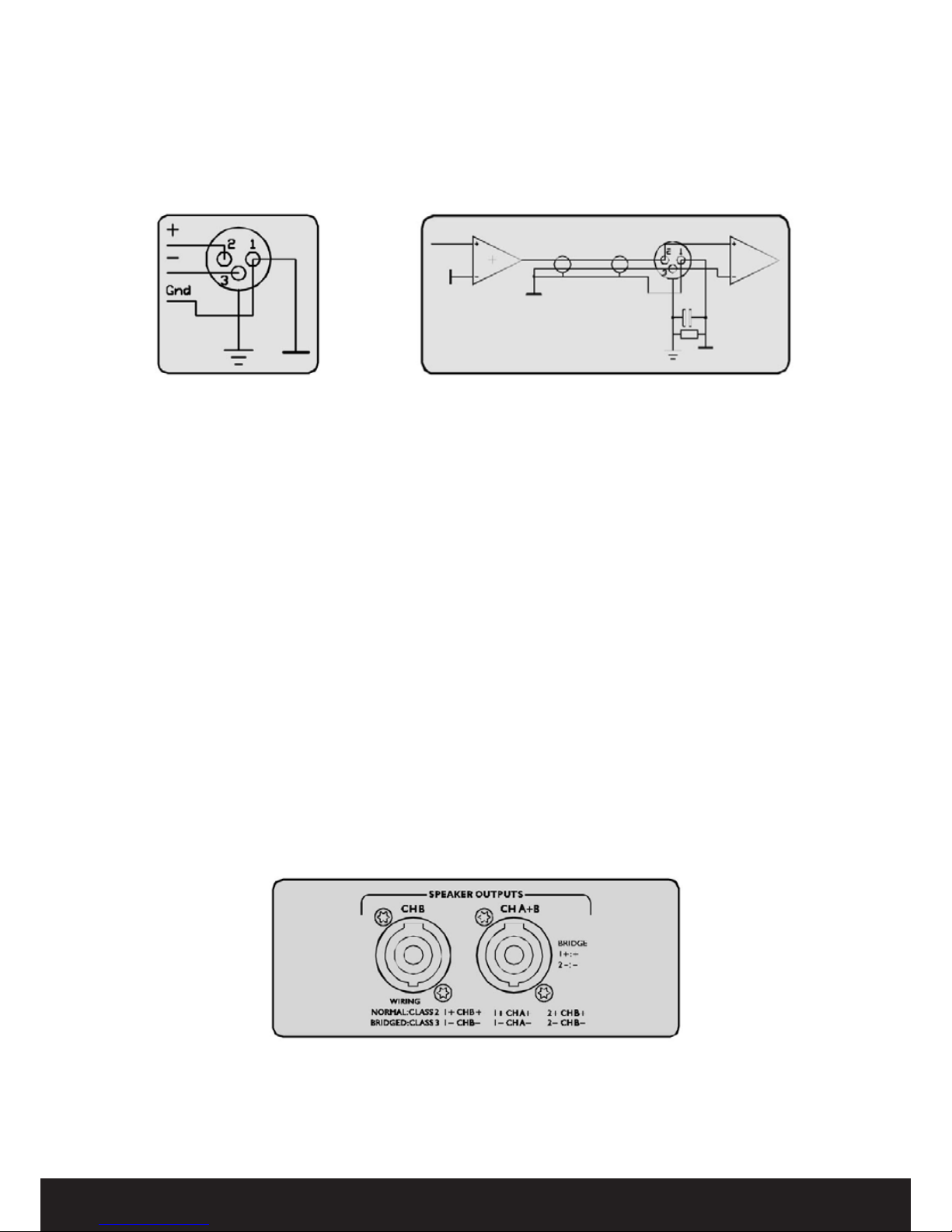
The XLR input connectors are electronically balanced, and
wired according to the IEC 268 standard (pin 2 = hot). XLR
input connectors should be wired as follows:
PIN1: Ground/protection
PIN2: Hot (+)
PIN3: Cold (-)
Los conectores de entrada XLR son electrónicamente
balanceados y se encuentran congurados conforme los
estándares IEC 268 (pin 2: caliente). El cableado de los conectores
XLR de entrada debe efectuarse de la siguiente manera:
PIN1: Tierra/ protección
PIN2: Caliente (+)
PIN3: Frío (-)
BALANCED XLR WIRING
SCHEMATIC / ESQUEMA DE
CABLEADO XLR BALANCEADO
UNBALANCED XLR WIRING SCHEMATIC
/ ESQUEMA DE CABLEADO XLR DESBALANCEADO
Unbalanced input connections
To connect an input to an unbalanced source, it is possible to
connect pins 1 and 3 in the XLR plug at the amplier end of
the cable. However, a better method is to connect pin 3 to the
shield at the source end of the cable, as this usually results in
better hum and noise rejection. Balanced input connections
are recommended whenever possible.
Para enlazar una entrada a una fuente no balanceada,
es posible conectar los pins 1 y 3 en el conector XLR en el
extremo del amplicador del cable. Sin embargo, un método
más efectivo consiste en conectar el pin 3 a la protección en
el extremo de inicio del cable, dado que de este modo se
minimiza el zumbido y el ruido. Se recomienda la utilización
de conexiones de entrada balanceadas.
Speakon output connections
Refer to the instructions in this section if your amplier is
equipped with the Speakon output connectors.
Si su amplicador se encuentra equipado con conectores de
salida Speakon, siga las instrucciones aquí consignadas.
SPEAKON OUTPUTS - TWO-CHANNEL MODELS
/ SALIDAS SPEAKON. MODELOS DE DOS CANALES
Conexiones Speakon de salida
Conexiones de entrada desbalanceada
Page 7
Two-channel ampliers
CHANNEL A AND B
INTO TWO SEPARATE
SPEAKONS / CANALES
A Y B EN DOS SPEAKONS
POR SEPARADO
CHANNEL A AND B
INTO ONE SPEAKON
(STEREO AND BIAMP) / CANALES A
Y B EN UN SPEAKON
(ESTÉREO Y BI-AMP)
BRIDGE (MONO) /
PUENTE (MONO)
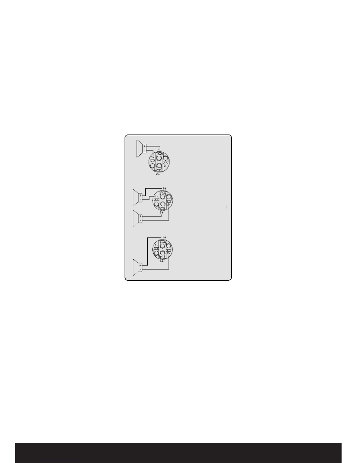
Two-channel ampliers are wired in the following manner.
The right Speakon connector, Channel A+B, provides outputs
for both Channel A and Channel B. This output is useful when
wiring the amplier for bridged mono operation. The left
Speakon connector provides an output for Channel B only.
Connect the + and - loudspeakers cables as shown in the
illustrations below.
El cableado de los amplicadores de dos canales se estructura
de la siguiente manera: el conector Speakon derecho, Canal
A+B, proporciona una salida para los canales A y B. Esta
salida es muy útil en los casos en los que se conecta el
amplicador para operaciones puente (mono). El conector
Speakon izquierdo proporciona la salida para el Canal B
exclusivamente.
Conecte los cables + y - del altavoz tal como se muestra en las
siguientes imágenes:
Amplier Gain
All DA Series ampliers feature adjustable input gain. This
versatility enables the amplier to accommodate a multitude
of system congurations with various input sources and
speaker layouts.
Amplier gain is set globally for all four channels. The ranges
is +23 dB to +44 dB in 3 dB steps. Individual channel ne
level adjustment is available using the potentiometers on the
front panel. The unique adjustable input gain feature of the
DA Series makes it easier to obtain the optimum between
headroom and balance signal-to-noise ratio. A “hot” input
signal, however, would require the gain to be raised in order
to achieve maximum output power with the lowest signal-
to-noise ratio. A “hot” input signal, however, would require
a lowering of the gain to avoid sending the amplier into
Voltage or Cur rent clipping.
Los amplicadores de Serie DA cuentan con una ganancia de
entrada ajustable. Esta versatilidad permite que el amplicador
se adapte a una gran cantidad de conguraciones del sistema
con distintas fuentes de entrada y diseños variables de altavoces.
Los valores de ganancia del amplicador son generales para
los cuatro canales. El margen abarca desde + 23 dB a + 44 dB
en pasos de 3 dB. Utilice los potenciómetros en el panel frontal
para lograr ajustes nos de nivel de los canales individuales.
Esta característica única de ajuste de ganancia de entrada de los
amplicadores de la Serie DA le permitirán alcanzar un balance
óptimo entre el headroom y la razón señal-ruido en el recorrido
de la señal. Una señal débil en la entrada podría requerir
aumentar la ganancia para así alcanzar la máxima potencia de
salida con la razón señal-ruido más baja. Sin embargo, una señal
de entrada “caliente” requiere una disminución de la ganancia
para evitar el clipping de voltaje o de corriente.
Ganancia del amplicador
Amplicador de dos canales
Page 8

See Appendix to review the table containing Gain versus VPL
setting implications for input sensitivity and output power.
NOTE: Bridge mode operation automatically compensates
by -6 dB, keeping all channels at the same gain.
Véase el Apéndice para información relativa a la ganancia y las
implicancias de la conguración del VPL en lo concerniente a
la sensibilidad de entrada y la potencia de salida.
NOTA: El funcionamiento en modo puente genera una
compensación automática de –6 dB y mantiene todos los
canales con la misma ganancia.
Channel gain/Level (Front-panel pots)
Individual channel gain (level) may be adjusted using the
potentiometers located on the front-panel behind the dust-
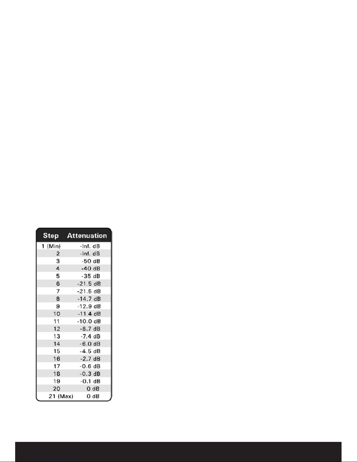
lter cover. Range is from 0 dB to -innity in 21 steps. The
attenuation is logarithmic, with the 12 o’clock position
indicating -10 dB.
Use your ngers or a screwdriver to adjust the potentiometers.
NOTE: If the level control is used to attenuate to a lower
level than the headroom relative to input sensitivity AND the
amplier input is driven into clip, there is a danger of clipping
the input stage before the current or voltage peak limiters are
activated.
Utilice los potenciómetros ubicados en el panel frontal, detrás de
la cubierta del ltro de polvo, para ajustar los niveles de ganancia
de los canales individuales. El margen abarca desde 0 dB hasta
menos innito, en 21 pasos. La atenuación es logarítmica. La
posición “12 en punto” indica una atenuación de –10 dB.
Ajuste los potenciómetros manualmente o con un destornillador.
NOTE: Si el control de nivel se utiliza para generar una
atenuación menor que el headroom relativo a la sensibilidad
de entrada y la entrada del amplicador es llevada hacia un
clip, existe el riesgo de que ocurra un clipping en la fase de
entrada antes de que los limitadores de voltaje o corriente
pico puedan activarse.
Amplier sensitivity
Sensitivity is dened as how many volts (rms) or dBu (referred
to 0.774 Vrms) are required to achieve full (maximum) output
power. As the output power varies with the load impedance,
4 ohms is usually the common reference.
Since DA Series ampliers are capable of providing multiple
maximum output power levels throught use of the VPL
feature, many sensitivity calculations may be required for a
single amplier.
El concepto de sensibilidad responde a la cantidad de voltios
(rms) o dBu (expresados en 0,775 Vrms) que se requieren
para obtener la máxima potencia de salida. Dado que ésta
varía conforme a la impedancia de carga, la referencia suele
ser equivalente a 4 ohms.
Como los amplicadores de Serie DA pueden generar
máximos niveles de potencia de salida a través de la utilización
del VPL, se podrían requerir múltiples cálculos de sensibilidad
para un único amplicador.
Sensibilidad del amplicador
Ganancia/nivel de canal (potenciómetros
del panel frontal)
Page 9
Output Voltage Peak Limiter (VPL)
Voltage Peak Limiter (VPL) is a unique feature in DA Series
ampliers. It is used to select the maximum power available
on each output channel. Eight levels can be set using the DIP-
switches on the amplier’s rear-panel.
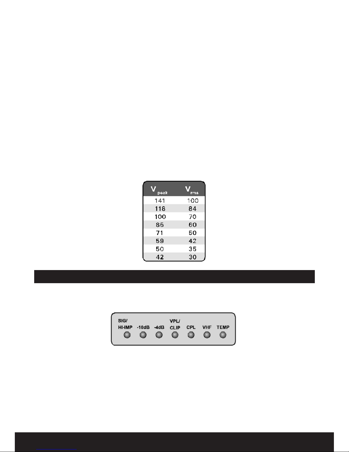
The values for VPL are displayed as maximum voltage peak
(V peak). To translate V peak into Vrms, you must divide the
Voltage Peak values by 1.41 (see table).
The VPL allows you to set the correct maximum output
peak power for optimum performance with the connected
speakers. The correct setting depends on the system type
(low- or high-impedance) and the specic load connected to
the channel. Since each channel can be congured to deliver
either very high voltage peak power OR high current draw at
low impedance, it is important to set the VPL correctly.
Limitador de Voltaje Pico de Salida (VPL)
El Limitador de Voltaje Pico (VPL) es una característica única de
los amplicadores de la serie DA. Se utiliza para seleccionar la
disponibilidad máxima de potencia para cada canal de salida.
Se pueden congurar ocho niveles con los interruptores DIP
ubicados en el panel trasero del amplicador.
Los valores del VPL se muestran como valores máximos de
voltaje pico (Vpeak). Para la conversión de voltaje pico a Vrms,
deberá dividir los valores de voltaje pico por 1,41 (véase tabla).
El VPL le permite congurar la máxima potencia pico de salida
que sea adecuada para un funcionamiento óptimo con los
altavoces conectados. La conguración correcta dependerá
del tipo de sistema (baja o alta impedancia) y de la carga
especíca que esté conectada al canal. Dado que cada canal
puede congurarse para enviar voltajes pico muy altos o para
producir un consumo de corriente alto a bajas impedancias,
resulta imprescindible congurar el VPL de modo correcto.
Front-Panel monitoring and adjustments / Monitoreo desde el panel frontal y ajustes.
Level indicators Indicadores de nivel
FRONT PANEL LED FIELD (PER-CHANNEL)
/ INDICADORES LED DEL PANEL FRONTAL
The front-panel displays an array of ten LED indicators for level
and status monitoring of each amplier channel. Indications
related to signal levels are as follows:
El panel frontal incluye diez LEDs para monitorear el nivel
y estado de cada canal del amplicador. Las indicaciones
relativas a los niveles de señal son las siguientes:
Page 10
• Red CPL (Current Peak Limiter) - Flashing indicates
that the output signal has reached the limit of the output
devices and limiting is in eect.
• Red VPL/CLIP - Indicates that signal has reached
maximum output voltage. (Maximum voltage is
determined by rear-panel VPL settings).
• Green -4dB - Indicates output signal has reached this level.
• Green -10 dB - Indicates output signal has reached this level.
• Signal / HI-IMP (Green / Red) - Indicates an oputput
signal above -44 dB. If it turns RED, this indicates that
a high-impedance (“Open” connection) has been
detected at the output. This can be a fault such as a
disconnected cable or malfunctioning loudspeaker
driver. However, if you could indicate acceptable
high impedance, such as a sub-bass enclosure with
high-impedance at a acertain frequency. When the
-10 dB signal LED is on AND the Hi-Imp. LED turns
red then the amplier has detected an open load
(no speaker is connected).
• CPL (limitador de corriente pico) rojo - Al estar
parpadeando, indica que la señal de salida ha alcanzado
el límite de las aplicaciones de salida y que el limitador se
encuentra activo.
• VPL/CLIP rojo - Indica que la señal ha alcanzado el
voltaje máximo de salida (el voltaje máximo se establece
a través de la conguración del VPL en el panel trasero).
• -4 dB verde - indica que la señal de salida ha alcanzado
este nivel.
• -10 dB verde - Indica que la señal de salida ha alcanzado este nivel.
• Signal / HI-IMP (Verde / Rojo) - indica que la señal
de salida se encuentra por encima de -44 dB. Si este
indicador es rojo, esto indica que se ha detectado
una situación de “alta impedancia” (conexión
“abierta”) en la salida, que puede ser resultado de
un cable desconectado o del mal funcionamiento
de algún altavoz. Sin embargo, también puede
indicar una situación de alta impedancia que sea
aceptable, por ejemplo, un recinto de sub-bajos
con alta impedancia a cierto nivel de frecuencia. Si
se enciende el LED de -10 dB Y el LED HI-IMP es rojo,
esto signica que el amplicador ha detectado una
carga abierta (ningún altavoz conectado).
Level adjust
Level adjust potentiometers (one per
channel) are located behind the removable
dust-lter cover on the amplier’s front-
panel. It is not possible to adjust the level
settings with the cover in place.
The potentiometer’s operational range is
0 dB to innity in 21 steps. Attenuation
is logarithmic, with 12 o’clock position
being -10 dB. See table to the left with
increments.
Mute indication
Individual channel Mute is indicated by
illumination of the two yellow LEDs at
the top of the channel’s LED bargraph. If
both LED’s are illuminated and all other
indications are normal, then the channel
has been muted. Otherwise, a Mute could
indicate a fault condition. (See chart).
Ajuste de nivel
Los potenciómetros de ajuste de nivel (uno por
canal) se ubican detrás de la cubierta desmontable
del filtro de polvo ubicada en el panel frontal
del amplificador. No es posible ajustar las
configuraciones de nivel con la cubierta.
El margen operacional de los
potenciómetros es desde 0 dB a menos
innito en 21 pasos. La atenuación es
logarítmica, con -10 dB en la posición “12 en
punto”. Véase la tabla con los incrementos.
Indicación de silencio
El silenciamiento de canales individuales se
indica con el encendido de los dos LED amarillos
ubicados en la parte superior de la barra gráca
de LED del canal. Si se encienden ambos LED
y los demás indicadores se encuentran en
estado normal, esto signica que ese canal
ha sido silenciado por un comando desde el
panel frontal del NLB 60E. De lo contrario, el
indicador MUTE podría indicar una falla (véase
a continuación).
Page 11
Performance, Warning and Fault indicators /
Indicadores de funcionamiento, de advertencias y de fallas
Global indicators:
• Power on/o (Green) - Indicates that
mains power is switched on.
• PAL, Power Average Limiter (Red) -
Indicates taht the amplier is limiting because
the power supply and/or the mains-inlet fuse
has reached maximum capability.
• Bridge mode (Yellow) - Indicates if two
channels are bridged using the DIP-switch on
the rear panel.
Global indicators:
• Power on/o (Verde) - Indica el encendido
del suministro eléctrico.
• PAL, Power Average Limiter (Rojo)
- Indica que el amplicador se encuentra
limitado, dado que el suministro eléctrico o el
fusible de la entrada de red ha alcanzado su
máxima capacidad.
• Bridge mode (Amarillo) - Indica si se
encuentran puenteados dos canales a través
del interruptor DIP del panel trasero.
Channel indicators Indicadores de canales
FRONT PANEL LED FIELD (PER-CHANNEL)
/ INDICADORES LED DEL PANEL FRONTAL
• CPL (Current Peak Limiter) (Red) - When ashing
indicates the maximum possible current draw has been
reached.
• CPL, Current Peak Limiter - Red stant indicates
excessive current draw caused by a short circuit on the
output or very low operational impedance. MUTE LED will
illuminate and the output will mute for 6 seconds before
re-measuring the output impedance. This will continue until
the short circuit is removed. CPL remains constant orange
in a fault condition only when an input signal is present.
• Temperature (Yellow) - Warning is indicated by a
ashing LED. If the amplier into thermal protect (Output
muted), the TEM LED illuminates constant orange and the
red MUTE LED illuminates.
• VHF, Very High Frequency protection (Yellow)
- Indicates that potentially harmful continuous high
frequecies have been detected on the input. The output
is muted (MUTE LED on).
• Hardware fault - Indicates when both the CPL
and TEM, VHF and MUTE indicators light up
simultaneously. The amplier requires service
before placing back in operation.
• CPL - Limitador de Corriente Pico (Rojo) - Al estar
parpadeando, indica que se ha alcanzado el nivel máximo
de consumo de corriente.
• CPL - Limitador de Corriente Pico - Al estar rojo
constante, indica un consumo excesivo de corriente
originado por un cortocircuito en la salida o por muy
baja impedancia operacional. Se encenderá el LED MUTE
y las salidas se silenciarán por 6 segundos para medir
nuevamente la impedancia de salida. Esto continuará
hasta que se elimine el cortocircuito. El CPL se mantendrá
encendido constantemente en naranja y en condición de
falla sólo cuando exista una señal de entrada.
• Temperatura (Amarillo) - Al estar parpadeando, indica
una advertencia de temperatura. Si el amplicador pasa al
modo de protección térmica (salidas silenciadas), el LED TEM
se encenderá en amarillo constante y el LED MUTE, en rojo.
• VHF - protección contra frecuencias muy altas
(Amarillo) - Indica que se han detectado frecuencias altas y
continuas en la señal de entrada que podrían causar daños. Se
silenciará la salida (LED MUTE encendido).
• Falla de Hardware - Se advierte cuando los
indicadores CPL, TEM, VHF y MUTE se encienden
de manera simultánea. Esta situación requiere el
servicio técnico del amplicador para continuar
funcionando.
Page 12

 Loading...