

Page 1

Hardware Installation Manual
AudioCodes MediaPack Analog Gateway Series
MP-1288
High-Density Analog Media Gateway
Version x.y
Page 2

Notice
MP-1288 | Hardware Installation Manual
Notice
Information contained in this document is believed to be accurate and reliable at the time
of printing. However, due to ongoing product improvements and revisions, AudioCodes
cannot guarantee accuracy of printed material after the Date Published nor can it accept
responsibility for errors or omissions. Updates to this document can be downloaded from
https://www.audiocodes.com/library/technical-documents.
This document is subject to change without notice.
Date Published: July-14-2020
WEEE EU Directive
Pursuant to the WEEE EU Directive, electronic and electrical waste must not be disposed of
with unsorted waste. Please contact your local recycling authority for disposal of this product.
Customer Support
Customer technical support and services are provided by AudioCodes or by an authorized
AudioCodes Service Partner. For more information on how to buy technical support for
AudioCodes products and for contact information, please visit our website at
https://www.audiocodes.com/services-support/maintenance-and-support.
Documentation Feedback
AudioCodes continually strives to produce high quality documentation. If you have any
comments (suggestions or errors) regarding this document, please fill out the Documentation
Feedback form on our website at https://online.audiocodes.com/documentation-feedback.
Stay in the Loop with AudioCodes
Notes and Warnings
Read and adhere to all warning statements in this document before installing the
device.
This device is considered as IPX0 non-water ingress protected and therefore, must be
installed only indoors.
- ii -
Page 3
Notice
MP-1288 | Hardware Installation Manual
The Ethernet port interface cabling must be shielded and routed only indoors.
The device must be connected to a grounded power outlet.
Routing of FXS telephony cables: Routing FXS telephony cables outdoors can be done
only in conjunction with a three-electrode Gas Discharge Tube (GDT) rated at 350V
located at the entry point of the two-wire into the building, and properly grounded. When
done correctly, the installation will meet ITU-T K.21 requirements.
Caution Electrical Shock: Do not open or disassemble this device. The device
carries high voltage and contact with internal components may expose you to electrical
shock and bodily harm.
The device must be installed and serviced only by qualified service personnel.
The device must be installed only in restricted access locations that are compliant with
ETS 300 253 guidelines where equipotential bonding has been implemented.
Disconnect the device from the mains and Telephone Network Voltage (TNV) before
servicing.
For AC powered models, use only the AC power cord that is supplied with the device to
connect to the power source.
Related Documentation
Document Name
SBC-Gateway Series Release Notes for Latest Release Versions
SBC-Gateway Series Release Notes for Long Term Support Versions
MP-1288 Media Gateway User's Manual
- iii -
Page 4

Notice
MP-1288 | Hardware Installation Manual
Document Revision Record
LTRT Description
28020 Initial document release.
28021 Cable anchor clip for power cord; adding FXS blade procedure (removing
connector covers).
28022 Physical dimensions updated; warning bulletin for 19-inch rack cabinet.
28023 AC power cable warning (Japanese).
28024 REN 3 update.
28025 Lifeline activation only upon power outage; FXS off-hook current.
28026 Fan tray section and air filter replacement section updated.
28027 Off-hook loop current and ring voltage updated regarding ports.
28028 Power surge warning updated.
28029 Air filter replacement statement.
28030 Logo updated.
28031 DC power supply added; package items updated; airflow illustration added.
28032 Note removed from environmental specifications.
28033 Off-hook loop current updated.
28034 Duration of press for reset to defaults; trademarks.
28035 Power Supply module hardware revisions note bulletin.
- iv -
Page 5

Content
MP-1288 | Hardware Installation Manual
Table of Contents
1 Introduction 1
2 Unpacking the Device 2
3 Physical Description 3
Physical Dimensions and Operating Environment 3
Front Panel Description 3
LED Descriptions 4
SYS LED 4
TEL LED 4
PWR LED 5
FAN LED 5
Fan Tray 6
Rear Panel Description 7
CPU Module 8
FXS Blades 9
Power Supply Module 12
AC Power Supply Module 12
DC Power Supply Module 13
LED Descriptions 14
Ethernet LEDs 14
STAT LED 14
FXS LEDs 14
Power Supply LED 16
4 19-Inch Rack Mounting 17
5 Cabling the Device 19
Grounding and Surge Protection 19
Connecting Ethernet Interfaces 21
Connecting FXS Interfaces 22
Connecting FXS Interfaces using AudioCodes FXS Patch Panel 24
Connecting FXS Interfaces using Centronics Cable 28
Connecting FXS Interfaces Directly to an MDF 29
Connecting the FXS Analog Lifeline 30
Connecting the Serial Interface to a Computer 32
Connecting to Power 34
AC Power Supply 34
DC Power Supply 36
6 Hardware Maintenance 39
Preventing Electrostatic Discharge Damage 39
Replacing the Fan Tray Module 39
Replacing the Air Filter 41
Replacing FXS Blades 43
- v -
Page 6

Content
MP-1288 | Hardware Installation Manual
Adding an FXS Blade 46
Replacing the CPU Module 49
50
Replacing Power Supply Modules 51
- vi -
Page 7

CHAPTER1 Introduction
1 Introduction
This document provides a hardware description of AudioCodes MP- 1288 Analog Media
Gateway (hereafter referred to as device) and step-by-step procedures for mounting and
cabling the device.
The device supports the following:
■ Up to 288 FXS ports, 72 FXS ports per FXS blade (can house up to four FXS blades)
■ Two 100/1000 Base-T Gigabit Ethernet ports
■ Fan Tray module
■ 1+1 AC or DC Power Supply modules
Hardware configurations may change without notice. Currently available hardware
configurations are listed in AudioCodes Price Book. For available hardware
configurations, contact your AudioCodes sales representative.
MP-1288 | Hardware Installation Manual
- 1 -
Page 8

CHAPTER2 Unpacking the Device
2 Unpacking the Device
Follow the procedure below for unpacking the carton in which the device is shipped.
➢ To unpack the device:
1. Open the carton and remove packing materials.
2. Remove the chassis from the carton.
3. Check that there is no equipment damage.
4. Ensure that in addition to the chassis, the package contains the following items:
● 2 x front-mounting brackets for 19-inch rack mounting
● 1 x RJ-45 to DB-9 serial cable adapter for serial communication
● For AC-powered models: 2 x AC power cords
MP-1288 | Hardware Installation Manual
● For DC-powered models: 2 x DC terminal blocks
● 1 x grounding lug
5. Check, retain and process any documents.
If there are any damaged or missing items, notify your AudioCodes sales representative.
- 2 -
Page 9
CHAPTER3 Physical Description
3 Physical Description
This section provides a physical description of the device.
Physical Dimensions and Operating Environment
The device's physical dimensions and operating environment are listed in the following table:
Table 3-1: Physical Dimensions and Operating Environment
MP-1288 | Hardware Installation Manual
Physical
Specification
Dimensions (H x W xD)3U high, 19-inch rack wide
132.5 x 438 x 482.5 mm (5.22 x 17.24 x 19 inches)
Weight 21 kg (46.3 lbs.) for fully-populated chassis
Environmental
■ Operational: 0 to 40°C (41 to 104°F)
■ Storage: -40 to 70°C (-40 to 158°F)
■ Humidity: 5 to 90% non-condensing
■ Over-voltage protection and surge immunity: ITU-T K.21 (basic)
compliant
Description
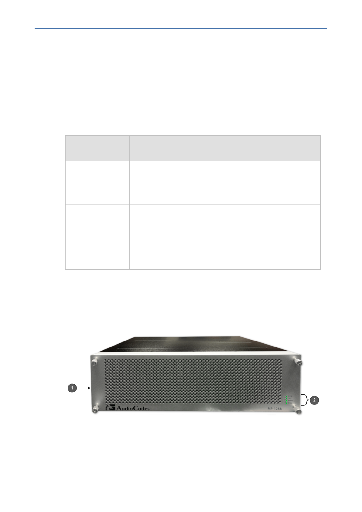
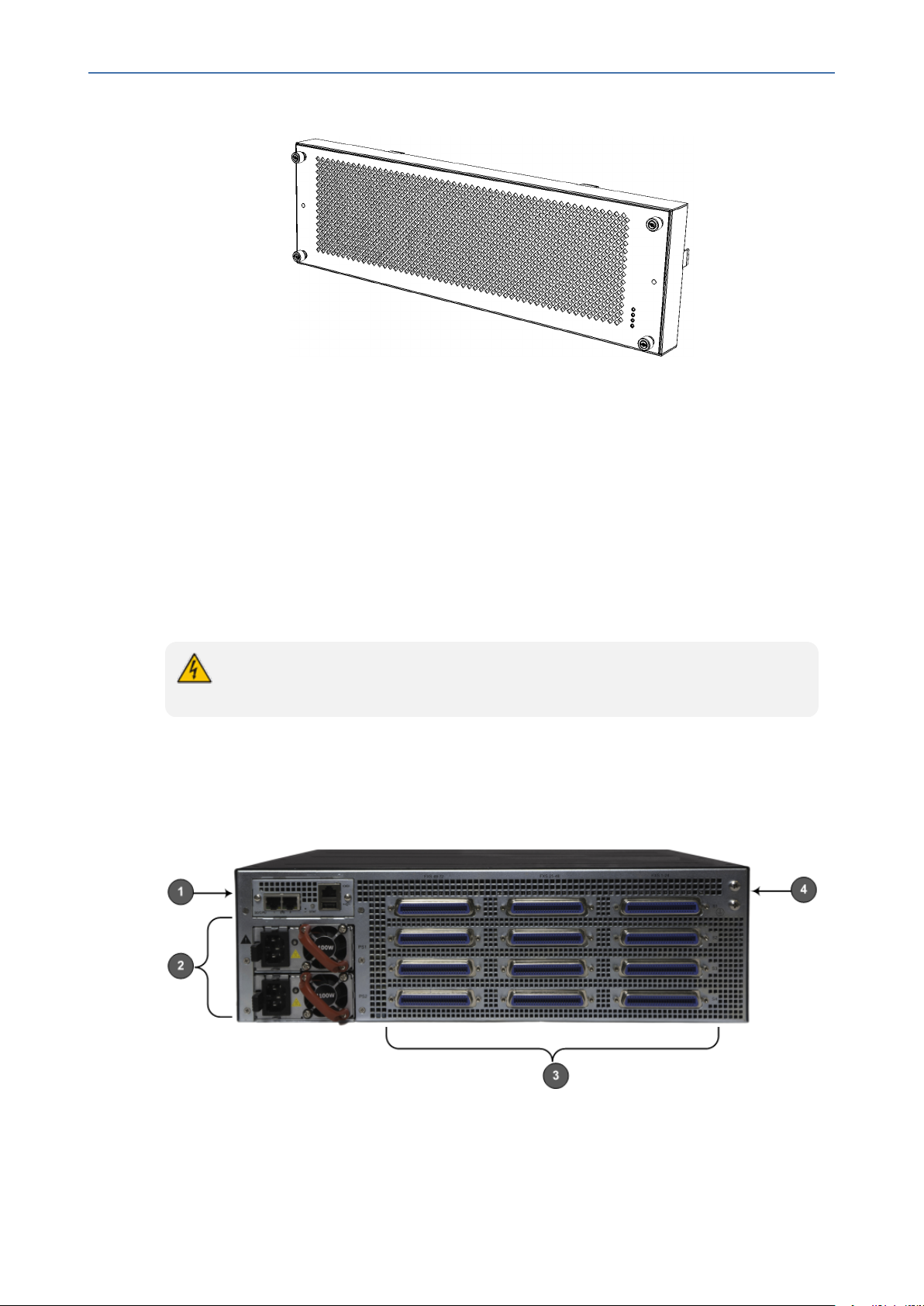
Front Panel Description
The device's front panel is shown in the following figure and described in the subsequent table.
Figure 3-1: Front Panel
- 3 -
Page 10

CHAPTER3 Physical Description
MP-1288 | Hardware Installation Manual
Table 3-2: Front Panel Description
Item
#
1 -
Label Description
Fan Tray cover. For more information, see Fan Tray on
page6.
2 SYS / TEL / PWR /
FAN
Front-panel LEDs. For more information, see LED
Descriptions below.
LED Descriptions
This section describes the LEDs on the front panel of the chassis.
SYS LED
The SYS LED indicates the device's operating status, as described in the following table.
Table 3-3: SYS LED Description
Color State Description
Green On LED lit as a result of one of the following:
■ Device is operating normally
■ During first stage of boot up when device is powered on
Orange On Chassis is approaching high temperature threshold, but not yet critical
Red On LED lit as a result of one of the following:
■ Fault detected in CPU module
■ Incompatible or faulty software version (.cmp file) detected during
boot up
■ Approaching critical high temperature threshold
Off No power
TEL LED
The TEL LED indicates the status of the FXS blades, as described in the following table.
Table 3-4: TEL LED Description
Color State Description
Green On LED lit as a result of one of the following:
- 4 -
Page 11
CHAPTER3 Physical Description
Color State Description
Orange On At least one DSP hasreached the high temperature threshold.
Red On LED lit as a result of one of the following:
MP-1288 | Hardware Installation Manual
■ During booting up phase
■ During normal operation, indicating normal FXS blade operation
■ During initial phase of power-up
■ Failure detected in at least one FXS blade
■ No FXS blades detected in the chassis
-
Off
No power.
PWR LED
The PWR LED indicates the power status, as described in the following table.
Table 3-5: PWR LED Description
Color State Description
Green On Chassis receiving power and Power Supply modules are functioning
normally. If the device is configured to use only one Power Supply
module, the LED is lit if at least one of them is operating normally.
Red On One of the Power Supply modules is faulty (if device is configured to
use two Power Supply modules).
-
Off No power received by the device.
FAN LED
The FAN LED indicates the status of the Fan Tray module, as described in the following table.
Table 3-6: FAN LED Description
Color State Description
Green On
Red On
- Off
Fans are functioning normally.
At least one fan in the Fan Tray module is faulty.
No power.
- 5 -
Page 12
CHAPTER3 Physical Description
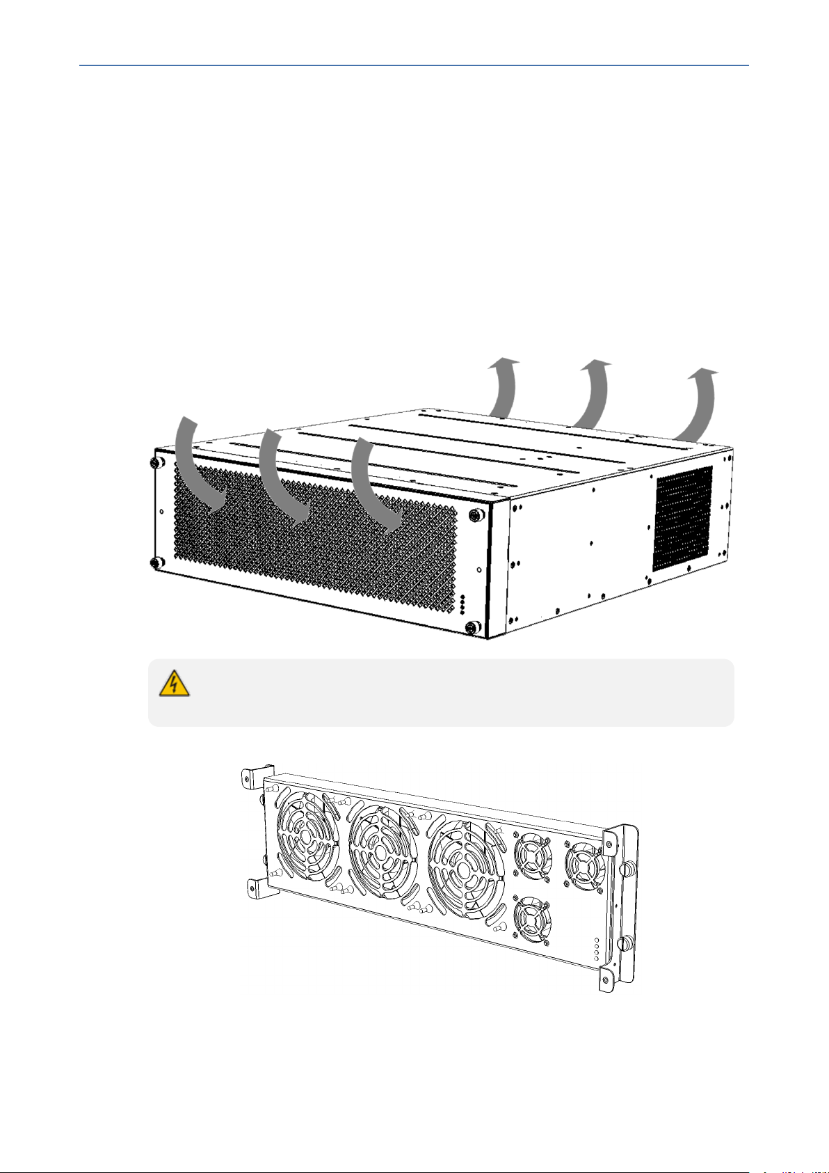
Fan Tray
The device provides a Fan Tray module, located on the front panel, which is concealed by a fan
tray cover. The Fan Tray module contains six individual fans which cool the device's internal
components to maintain an acceptable operating temperature inside the chassis.
The Fan Tray module draws air in from the outside through the perforated fan tray cover on
the front panel (see following figure). A replaceable air filter, located inside the fan tray cover,
removes dust particles from the sucked in air. The incoming air passes through the chassis,
cooling the internal components and then exits the chassis through the vents on the rear
panel (see following figure).
MP-1288 | Hardware Installation Manual
Figure 3-2: Airflow Directions through Chassis
When installing the chassis, make sure there is sufficient front- and rear-side clearance
for proper airflow into and out of the chassis.
Figure 3-3: Fan Tray Module
- 6 -
Page 13
CHAPTER3 Physical Description
The Fan Tray provides a LED indicating the operating status of the Fan Tray module. For more
information, see FAN LED on page5.
During system operation, the inner ambient temperature is continuously monitored. Upon
excessive temperature conditions, an SNMP Temperature Alarm is generated
(acBoardTemperatureAlarm). Upon a speed degradation or full stop of any fan, an SNMP Fan
Alarm (acFanTrayAlarm) is generated.
MP-1288 | Hardware Installation Manual
Figure 3-4: Fan Tray Cover
The Fan Tray module is hot-swappable, allowing you to replace it even when the device is
powered on. The Fan Tray module, fan tray cover, and air filter are available as fieldreplaceable units (FRU). For replacing the Fan Tray module, see Replacing the Fan Tray Module
on page39. For replacing the air filter, see Replacing the Air Filter on page41.
For replacing the Fan Tray module or any of its components, perform only the
instructions as described in Replacing the Fan Tray Module on page39.
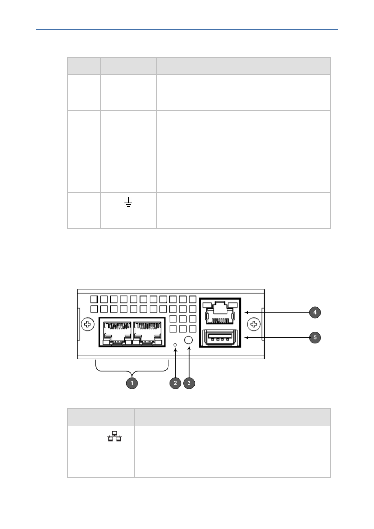
Rear Panel Description
The device's rear panel is shown in the following figure and described in the subsequent table.
Figure 3-5: Rear Panel Description
The figure above is used only as an example. The number of installed FXS blades, and number
and type of Power Supply modules (AC or DC) depend on your ordered hardware
configuration.
- 7 -
Page 14
CHAPTER3 Physical Description
Item # Label Description
1 CPU CPU module providing the central processing unit and
MP-1288 | Hardware Installation Manual
Table 3-7: Rear Panel Description
various network port interfaces. For more information,
see CPU Module below.
2 PS1 / PS2
Power Supply modules. For more information, see Power
Supply Module on page12.
3 Blades: S1 / S2 /
S3 / S4
FXS blades providing FXS port interfaces. For more
information, see FXS Blades on the next page.
FXS Ports:FXS 1-
24 / FXS 25-48 /
FXS 49-72
4 Protective grounding for connecting a grounding lug for
chassis ground connection for ESD-preventive equipment
or a grounding wire.
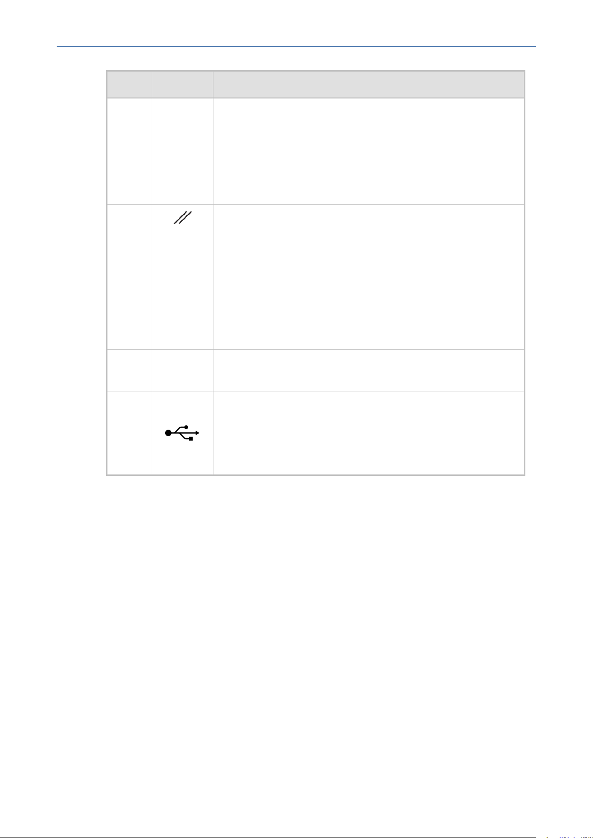
CPU Module
The CPU module provides the central processing unit and port interfaces, as shown in the
following figure and described in the subsequent table.
Figure 3-6: CPU Module
Table 3-8: CPU Module Description
Item # Label Description
1 Two 100/1000Base-T (Gigabit) Ethernet ports (RJ-45) for connecting
to the IP network.
The ports support the following features:
■ 1+1 Ethernet port redundancy
- 8 -
Page 15
CHAPTER3 Physical Description
Item # Label Description
MP-1288 | Hardware Installation Manual
■ Half- and full-duplex modes
■ Auto-negotiation
■ Straight or crossover cable detection
The ports provide LEDs to indicate Ethernet status. For more
information, see Ethernet LEDs on page14.
2
Reset pinhole button for resetting the device and restoring
factory defaults:
■ To reset the device: Using a paper clip or any other similar
pointed object, press and hold down the button for at least 2
seconds (but no more than 10 seconds).
■ To restore the device to factory defaults: Using a paper clip or
any other similar pointed object, press and hold down the
button for at least 15 seconds (but no more than 30 seconds).
3 STAT LED indicating the status of the CPU module. For more
information, see STAT LED on page14.
4 |O|O| RJ-45 port for RS-232 serial communication.
5 USB Type-A port which can be used, for example, for various
storage capabilities to an external USB hard drive or flash disk (disk
on key).
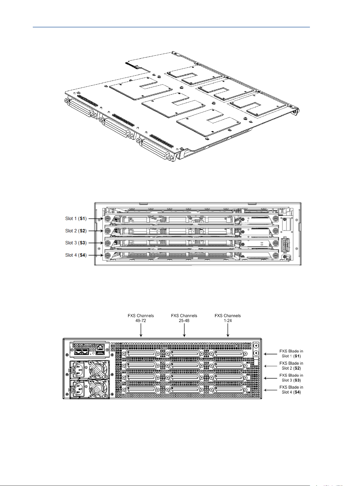
FXS Blades
The FXS blade (referred to as Module in the device's management interfaces) provides the FXS
port interfaces. Each blade provides three FXS port connectors - 50-pin Telco connector
(Centronics type). Each connector provides 24 FXS interfaces and therefore, each blade
provides up to 72 FXS interfaces (3 x 24 FXS). The device can be housed with up to four FXS
blades thereby, supporting up to 288 FXS port interfaces (4 blades x 72 FXS). The FXS blades are
available as spare parts. For replacing FXS blades, see Replacing the Fan Tray Module on
page39.
Each FXS blade provides a LED on the front and rear panel, as described in FXS LEDs on
page14.
- 9 -
Page 16
CHAPTER3 Physical Description
Figure 3-7: FXS Blade Showing Three FXS Telco Connectors
The chassis slot assignment for the FXS blades is shown in the following figure (front panel).
Note that the slot labels (S1, S2, S3 and S4) are located on the rear panel.
MP-1288 | Hardware Installation Manual
Figure 3-8: Chassis Slot Assignment for FXS Blades (Front Panel)
The FXS channel (port) number range of each FXS connector on an FXS blade is indicated by
the labels (FXS 1-24, FXS 25-48, and FXS 49-72) located on the rear panel above the FXS blades,
as shown in the following figure:
Figure 3-9: FXS Blades and FXS Channels per FXS Connector (Rear Panel)
The following table lists the specifications of the device's FXS ports.
- 10 -
Page 17

CHAPTER3 Physical Description
Specification Description
MP-1288 | Hardware Installation Manual
Table 3-9: FXS Port Specifications
Analog
Lifeline
(PSTN
Fallback)
Interface
Type
FXS
Signaling
Formats
FXS Loop
Impedance
Off-hook
Loop
Current
The FXS blade supports analog lifeline (PSTN Fallback). For more
information, see Connecting the FXS Analog Lifeline on page30.
FXS connection via 50-pin CHAMP connector
In-band signaling DTMF (TIA 464B)
Up to 1500 ohm (including phone impedance)
■ 25 mA (maximum) on all ports
■ 35 mA (maximum) on the first (1) and last (24) ports per FXS connector.
In other words, it applies to up to six ports per FXS Blade. This applies
to emergency / elevator phones.
Ring Voltage
(Sine)
■ 54 Vrms
■ 80 Vrms on six ports per FXS Blade (for emergency / elevator phones)
Note:
■ Balanced ringing only.
■ Simultaneous ringing of 288 phones (72 per FXS Blade given REN 3
load)
Ring
25-100 Hz
Frequency
Maximum
Ringer Equivalency Number (REN) 3
Ringer Load
Caller ID Bellcore GR-30-CORE Type 1 using Bell 202 FSK modulation, ETSI Type 1,
NTT, Denmark, India, Brazil, British and DTMF ETSI CID (ETS 300-659-1)
Polarity
Immediate or smooth to prevent erroneous ringing
Reversal /
Wink
Metering 12/16 KHz sinusoidal bursts; generation on FXS
- 11 -
Page 18
CHAPTER3 Physical Description
Specification Description
Tones
MP-1288 | Hardware Installation Manual
Distinctive
Ringing
Message
Waiting
Indication
(MWI)
By frequency (15-100 Hz) and cadence patterns
DC voltage generation (TIA/EIA-464-B); V23 FSK data; Stutter dial tone
Power Supply Module
The device can be powered from an AC or a DC power source. The type of power depends on
your ordered hardware configuration.
AC Power Supply Module
For the AC- powered model, the device provides two AC Power Supply modules for load
sharing and power redundancy. The power source is a standard electrical outlet providing AC
power.
Power surge protection, caused for example from lightning, is also supported. For more
information, see Grounding and Surge Protection on page19.
The Power Supply module is available as a spare part. The Power Supply modules are hotswappable and therefore, if only one needs to be replaced, it can be done while the device is
receiving power from the working Power Supply module. For replacing Power Supply modules,
see on page50.
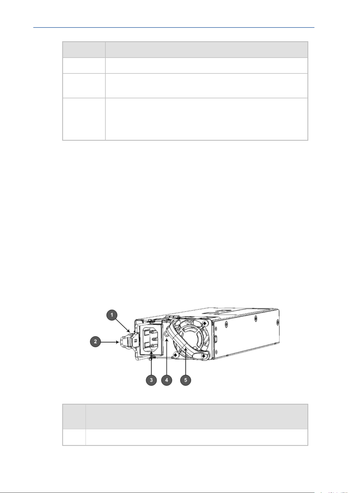
Figure 3-10: AC Power Supply Module
Table 3-10: AC Power Supply Module Description
Item
#
Description
1 Release latch for releasing and securing module from / to chassis slot.
- 12 -
Page 19

CHAPTER3 Physical Description
MP-1288 | Hardware Installation Manual
Item
#
Description
2 Power cord anchor clip.
3 3-Prong power inlet.
4
LED for indicating power status. For more information, see Power Supply LED on
page16.
5 Handle for extracting and installing module.
The two Power Supply modules installed in the chassis must be of the same hardware
revision. For more information, see the note in on page50.
DC Power Supply Module
For the DC- powered model, the device provides two DC Power Supply modules for load
sharing and power redundancy.
Power surge protection, caused for example from lightning, is also supported. For more
information, see Grounding and Surge Protection on page19.
The Power Supply module is available as a spare part. The Power Supply modules are hotswappable and therefore, if only one needs to be replaced, it can be done while the device is
receiving power from the working Power Supply module. For replacing Power Supply modules,
see on page50.
Figure 3-11: DC Power Supply Module
Table 3-11: DC Power Supply Module Description
Item # Description
1 Release latch for releasing and securing module from / to chassis slot.
2 DC power inlet.
3 Handle for extracting and installing module.
- 13 -
Page 20

CHAPTER3 Physical Description
LED Descriptions
This section describes the LEDs on the rear panel of the chassis.
Ethernet LEDs
Each Ethernet port on the CPU module provides a LED (located on its left) which indicates
network connectivity status, as described in the following table.
Color State Description
Green On Ethernet link established.
MP-1288 | Hardware Installation Manual
Table 3-12: Ethernet LEDs Description
Flashing Data is being received or transmitted.
-
Off No Ethernet link.
STAT LED
The STAT LED on the CPU module indicates the operating status of the CPU module, as
described in the following table.
Table 3-13: STAT LED Description
Color State Description
Green On LED is lit because of one of the following:
■ Device is operating normally
■ During first stage of boot up when device is powered on
Orange On Chassis is approaching high-temperature threshold, but not yet critical
Red On LED is lit because of one of the following:
■ Fault detected in CPU module
■ Incompatible or faulty software version (.cmp file) detected during
boot up
■ Approaching critical high-temperature threshold
-
Off
No power.
FXS LEDs
Each FXS blade provides two LEDs that indicate the status of the FXS blade, as described in the
following table. Both LEDs indicate the same status information. One LED is located on its front
- 14 -
Page 21

CHAPTER3 Physical Description
panel and the other LED on its rear panel to the left of the left-most FXS port (labeled FXS 49-
72), as shown in the following figures:
Figure 3-12: FXS LED Location on Front Panel per FXS Blade
Figure 3-13: FXS LED Location on Rear Panel per FXS Blade
MP-1288 | Hardware Installation Manual
Table 3-14: FXS LEDs Description
Color State Description
Green On FXS blade initialization completed and is functioning normally.
Orange On Some (less than a third) FXS ports are out of service.
Red On FXS blade initialization has not completed or a failure detected in the
FXS blade due to any of the following:
■ Multiple FXS ports (more than a third) are out of service
■ DSP failure
-
Off No power.
- 15 -
Page 22

CHAPTER3 Physical Description
Power Supply LED
The Power Supply module, located on the chassis rear panel, provides a LED which indicates
the operating status of the module, as described in the following table.
Color State Description
Green On Connected to power source, chassis receiving power, and
Amber Flashing Connected to power source, but chassis not receiving power or
MP-1288 | Hardware Installation Manual
Table 3-15: Power Supply Module LED Description
Power Supply module's fan operating normally.
fault detected in Power Supply module's fan.
If the chassis houses two Power Supply modules, but only one
of them is connected to the power source, the LED on the
Power Supply module that is not connected flashes amber.
-
Off No power received from power source.
- 16 -
Page 23

CHAPTER4 19-Inch Rack Mounting
4 19-Inch Rack Mounting
The device is designed to be mounted in a standard 19-inch rack. This is done by attaching it to
the rack's posts using front-mounting brackets (supplied).
At least two people are required to mount the device in the 19-inch rack.
Avertissements: Au moins deux personnes sont nécessaires pour monter l’appareil
dans le bâti 19 pouces.
A fully-populated chassis weighs up to 21 kg (46.3 lbs.). The 19-inch rack cabinet must
be able to withstand this weight.
Rack Mount Safety Instructions: When installing the chassis in a rack, adhere the
following safety instructions:
● Elevated Operating Temperature: If installed in a closed or multi-unit rack
assembly, the operating ambient temperature of the rack environment may be
greater than room ambient temperature. Therefore, consideration should be given
to installing the equipment in an environment compatible with the maximum
ambient temperature (Tma) of 40°C (104°F).
● Reduced Air Flow: Installation of the equipment in a rack should be such that the
amount of air flow required for safe operation on the equipment is not
compromised.
● Mechanical Loading: Mounting of the equipment in the rack should be such that a
hazardous condition is not achieved due to uneven mechanical loading.
● Circuit Overloading: Consideration should be given to the connection of the
equipment to the supply circuit and the effect that overloading of the circuits might
have on over-current protection and supply wiring. Appropriate consideration of
equipment nameplate ratings should be used when addressing this concern.
● Reliable Earthing: Reliable earthing of rack-mounted equipment should be
maintained. Particular attention should be given to supply connections other than
direct connections to the branch circuit (e.g., use of power strips.)
MP-1288 | Hardware Installation Manual
➢ To mount the device in a 19-inch rack:
1. Attach the two front-mounting brackets (supplied) to both sides of the chassis, as shown
in the following figure. Each bracket is secured to the chassis using 9 screws (supplied).
- 17 -
Page 24

CHAPTER4 19-Inch Rack Mounting
Figure 4-1: Attaching Mounting Brackets to Chassis
2. With two people, lift the chassis into the rack from the front of the rack.
3. Hold the chassis for support while the second person positions the chassis in the rack so
that the front-mounting brackets are flush against the front-rack posts and that the holes
of the front-mounting brackets aligned with the holes on the front-rack post, as shown in
the following figure:
MP-1288 | Hardware Installation Manual
Figure 4-2: Front-Mounting Brackets Flush and Aligned with Front Rack Posts
4. Hold the chassis in position while the second person secures the two front-mounting
brackets to the front posts, by finger-tightening 19-inch rack bolts (not supplied) to the
rack posts. Each mounting bracket is secured to the rack by two bolts.
Make sure that the left and right front-mounting brackets are attached to the rack posts
at the same level so that the chassis is supported in a horizontal position.
5. Tighten the bolts on the front-mounting brackets.
- 18 -
Page 25

CHAPTER5 Cabling the Device
5 Cabling the Device
This section describes how to cable the device:
■ Connecting to earth / ground – see Grounding and Surge Protection below
■ Connecting to the LAN – see Connecting Ethernet Interfaces on page21
■ Connecting the FXS interfaces – see Connecting FXS Interfaces on page22
■ Connecting the FXS lifeline – see Connecting the FXS Analog Lifeline on page30
■ Connecting to a PC for serial communication – see Connecting the Serial Interface to a
Computer on page32
■ Connecting to power – see Connecting to Power on page34
Grounding and Surge Protection
MP-1288 | Hardware Installation Manual
The following procedure describes how to ground the device.
Grounding and Power Surge Protection:
● The device must be installed only in telecommunication sites / centers in
compliance with ETS 300-253 requirements "Earthing and Bonding of
Telecommunication Equipment in Telecommunication Centers".
● Prior to installation, earth loop impedance test must be performed by a certified
electrician to ensure grounding suitability at the power outlet intended to feed the
unit. It is essential that the impedance will be kept below 0.5 ohms!
● Proper grounding is crucial to ensure the effectiveness of the lightning protection,
connect the device permanently to ground (as described in the procedure below).
The device's grounding screw must be connected to the equipotential grounding
bus bar located in the Telecommunication rack or installation site, using a wire of 6
mm2surface wire. If the device is installed in a rack with other equipment, the rack
must be connected to the equipotential grounding bus bar of the
Telecommunication room, using a stranded cable with surface area of 25 mm2.
The length of this cable must be as short as possible (no longer than 3 meters).
Protective Earthing:
● The equipment is classified as Class I EN 60950 and UL 60950 and must be
earthed at all times (using an equipment-earthing conductor).
● Finland: "Laite on liltettava suojamaadoituskoskettimilla varustettuun
pistorasiaan."
● Norway: "Apparatet rna tilkoples jordet stikkontakt."
● Sweden: "Apparaten skall anslutas till jordat uttag."
➢ To connect the chassis to an earth ground:
1. Prepare an adequate length (maximum 20 mm or 0.8 in.) of stranded grounding wire (16
AWG minimum size) for the ground connection, as shown in the following figure:
- 19 -
Page 26

CHAPTER5 Cabling the Device
2. Using a Philips-head screwdriver, remove the two screws and their spring washers for
attaching the grounding lug, located on the chassis' rear panel as shown in the following
figure:
MP-1288 | Hardware Installation Manual
Figure 5-1: Stripped Grounding Wire
Figure 5-2: Removing Screws and Washers
3. Insert one end of the grounding wire into the grounding lug (supplied), as shown in the
following figure, and then use a crimping tool (not supplied) to secure the wire to the
grounding lug:
Figure 5-3: Attaching Grounding Wire to Grounding Lug
4. Attach the grounding lug (supplied) to the chassis using the two screws.
5. Attach the grounding lug to the chassis, as shown in the following figure. Make sure that
the spring washers are located between screw head and lug.
Figure 5-4: Attaching Grounding Lug to Chassis
- 20 -
Page 27

CHAPTER5 Cabling the Device
6. Connect the other end of the grounding wire to the building protective earth. This should
be in accordance with the regulations enforced in the country in which the device is
installed.
Connecting Ethernet Interfaces
The device provides two 100/1000Base-T Gigabit Ethernet ports (RJ-45) for connecting to the IP
network (e.g., LAN). The ports support half- and full-duplex modes, auto-negotiation, and
straight or crossover cable detection.
The ports can operate as a pair (Ethernet Group) to provide 1+1 port redundancy, where one
port serves as the active port while the other as standby. When the active port fails, the device
switches to the standby port.
The cabling specifications and procedure for connecting the device to the LAN is as follows:
■ Cable: Straight-through, Category (Cat) 5/5e/6 cable
■ Connector: Standard RJ-45
MP-1288 | Hardware Installation Manual
■ Connector Pinouts:
Table 5-1: RJ-45 Connector Pinouts for Ethernet Ports
Pin Signal Name
1 Ethernet signal pair
2
3 Ethernet signal pair
6
4 Ethernet signal pair
5
7 Ethernet signal pair
8
Shield Chassis ground
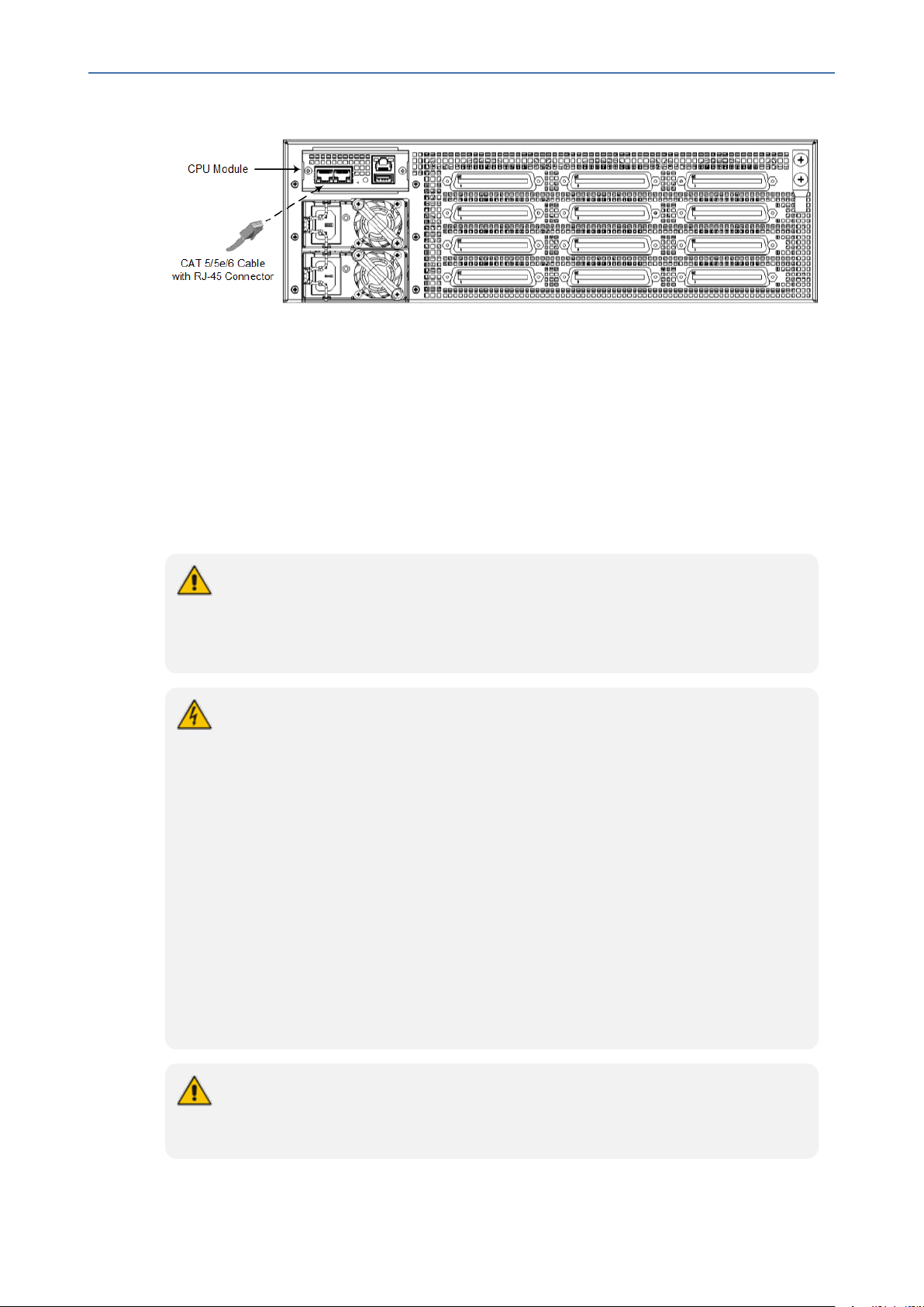
➢ To connect the Ethernet interfaces:
1. Connect the RJ-45 connector, at one end of a straight-through Cat 5e or Cat 6 cable, to
one of the Ethernet ports (labeled ) on the CPU module located on the chassis' rear
panel, as shown in the following figure:
- 21 -
Page 28
CHAPTER5 Cabling the Device
2. Connect the other end of the cable to your network.
3. For 1+1 Ethernet port redundancy, repeat steps 1 through 2 for the standby port. Make
sure that you connect each port to a different network (but in the same subnet).
Connecting FXS Interfaces
The device interfaces with the FXS analog telephone equipment (e.g., fax machines, modems,
or telephones) through the 50-pin Telco connectors provided on the FXS blades. For more
information on the FXS blades, see FXS Blades on page9.
MP-1288 | Hardware Installation Manual
Figure 5-5: Connecting the LAN Ports
Safety Notice:
● Make sure that the FXS ports are connected to the appropriate, external devices;
otherwise, damage to the device may occur.
● FXS ports are considered TNV-2.
FXS Outdoor Cabling and Power Surge Protection:
● The device includes an integrated secondary surge protection, but does not include
primary telecom protection! When the FXS telephone lines are routed outside the
building, additional protection - usually a 350V three-electrode Gas Discharge Tube
(GDT) as described in ITU-T K.44 - must be provided at the entry point of the
telecom wires into the building (usually on the main distribution frame / MDF), in
conjunction with proper grounding. The center pin of the GDT (MDF grounding bar)
must be connected to the equipotential grounding bus bar of the
Telecommunication room.
● Failing to install primary surge protectors and failing to comply with the grounding
instructions or any other installation instructions, may cause permanent damage to
the device!
● The device complies with protection levels as required by EN 55024/EN 300386.
Higher levels of surges may cause damage to the device.
● To protect against electrical shock and fire, use a minimum of 26-AWG wire size to
connect the FXS ports.
To configure the current (mA) that the device supplies to the FXS ports in off-hook
state, use the EnhancedFXSLineCurrent parameter. Configuration is applicable only to
the first and last ports (e.g., 1 and 24) on each FXS connector. For more information,
- 22 -
Page 29

CHAPTER5 Cabling the Device
refer to the User's Manual.
The FXS cabling specifications include the following:
■ Cable: You can use any of the following cables:
● AudioCodes orderable FXS Patch Panel (see Connecting FXS Interfaces using
AudioCodes FXS Patch Panel on the next page)
● AudioCodes orderable Centronics cable connector (10 m) to open leads, which needs
to be connected to a distribution panel (see Connecting FXS Interfaces using
Centronics Cable on page28)
● Third-party, main distribution frame (MDF) connector (see Connecting FXS Interfaces
Directly to an MDF on page29)
■ Connector Type: 50-pin Telco
MP-1288 | Hardware Installation Manual
Figure 5-6: 50-pin Telco Connector
■ Connector Pinouts:
Table 5-2: 50-pin Telco Connector Pinouts
FXS Phone Channel
(Ports)
Connector Pins
1 1/26
2 2/27
3 3/28
4 4/29
5 5/30
6 6/31
7 7/32
8 8/33
9 9/34
- 23 -
Page 30

CHAPTER5 Cabling the Device
MP-1288 | Hardware Installation Manual
FXS Phone Channel
(Ports)
Connector Pins
10 10/35
11 11/36
12 12/37
13 13/38
14 14/39
15 15/40
16 16/41
17 17/42
18 18/43
19 19/44
20 20/45
21 21/46
22 22/47
23 23/48
24 24/49
25 for Analog Lifeline 25/50
For analog Lifeline cabling, see Connecting the FXS Analog
Lifeline on page30.
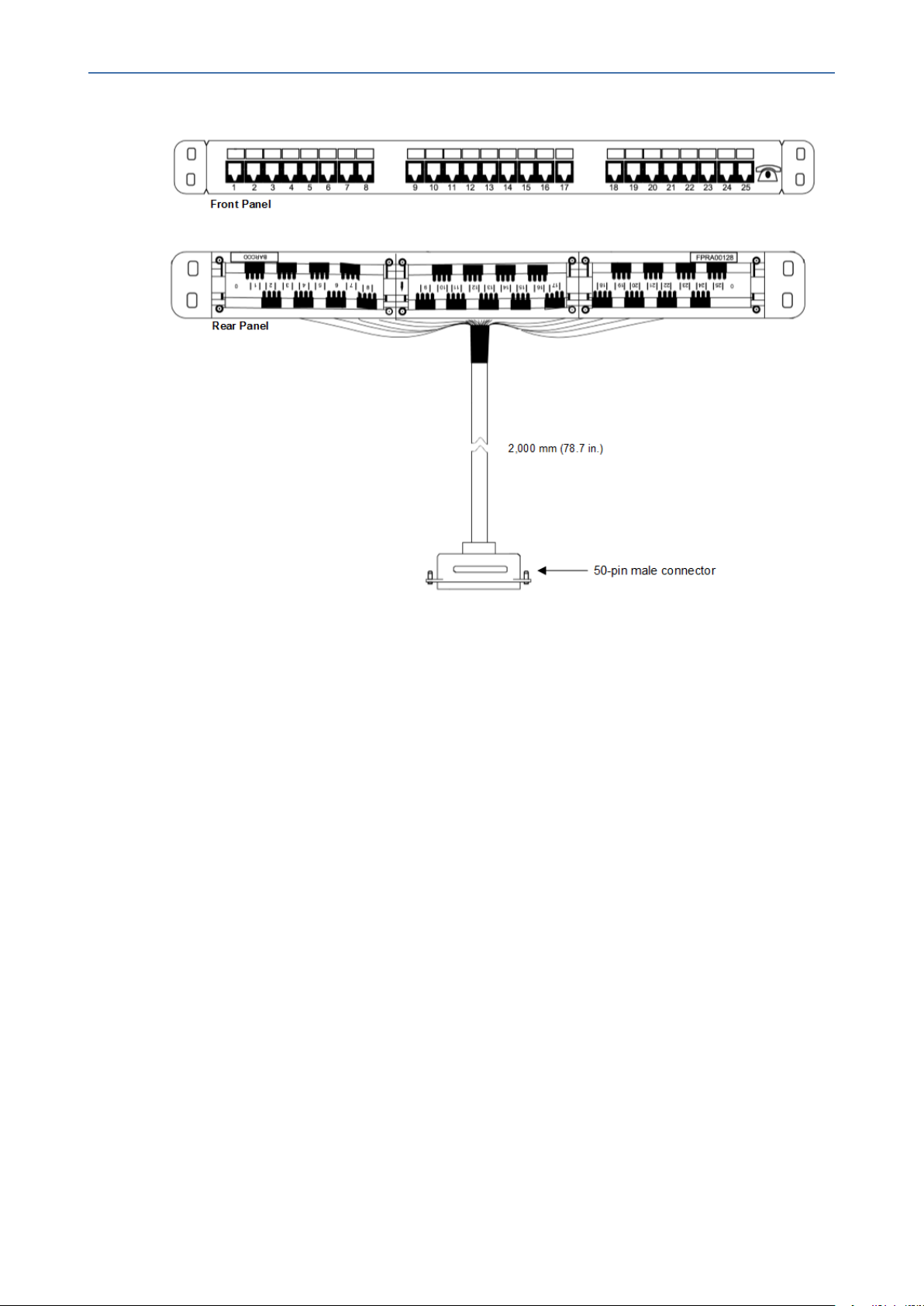
Connecting FXS Interfaces using AudioCodes FXS Patch Panel
You can purchase AudioCodes' FXS Patch Panel (shown in the following figure) to connect the
FXS interfaces to FXS equipment. The patch panel can be mounted in a 19-inch rack using
integrated mounting brackets and provides a 2-meter (78.7 in.) extension cable with a 50-pin
male connector for connection to the FXS port on the FXS blade. All incoming wires from the
50-pin Telco connector are terminated to the back of the patch panel. The FXS endpoints (e.g.
telephones) can be plugged into the corresponding RJ-11 jacks on the front of the patch panel.
- 24 -
Page 31
CHAPTER5 Cabling the Device
MP-1288 | Hardware Installation Manual
Figure 5-7: Orderable FXS Patch Panel
➢ To connect the FXS interfaces using the FXS Patch Panel:
1. Mount the Patch Panel in a 19-inch rack, using the integrated mounting brackets located
on either side of the Patch Panel. Use four 19-inch rack bolts (not supplied) to securely
attach the brackets to the front-rack posts. Make sure that the left and right mounting
brackets are attached to the rack posts at the same level so that the patch panel is
supported in a horizontal position.
- 25 -
Page 32

CHAPTER5 Cabling the Device
MP-1288 | Hardware Installation Manual
Figure 5-8: Mounting Patch Panel in Rack
2. Connect the Patch Panel's 50-pin male connector to one of the FXS blade's 50-pin female
Telco connectors located on the chassis' rear panel, and secure the connector with the
two captive screws located on either side of the connector, using a flat-head screwdriver:
Figure 5-9: Connecting 50-Pin Telco Connector to Port on FXS Blade
3. Connect your analog equipment to the Patch Panel, by plugging the RJ-11 connectors into
the RJ-11 sockets on the Patch Panel's front panel:
- 26 -
Page 33

CHAPTER5 Cabling the Device
Figure 5-10: Connecting Analog Equipment to FXS Patch Panel
For outdoor FXS cabling installations, you must install additional power surge protection as
illustrated in the following figure. For indoor FXS cabling installations, there is no need for
primary lightning protection usage.
Figure 5-11: Connecting FXS Interfaces using FXS Patch Panel
MP-1288 | Hardware Installation Manual
- 27 -
Page 34

CHAPTER5 Cabling the Device
Connecting FXS Interfaces using Centronics Cable
You can purchase AudioCodes' Centronics-type cable connector, as shown in the following
figure, to connect the FXS interfaces to FXS equipment. The 10-meter cable (32.8 ft.) provides a
50-pin male Telco connector on one end and open leads on the other end, which need to be
connected to your patch panel or distribution frame.
MP-1288 | Hardware Installation Manual
Figure 5-12: Orderable Centronics Cable and Pinouts
➢ To connect the FXS interfaces using the Centronics cable:
1. Connect the 50-pin male connector on end of the cable to one of the FXS blade's 50-pin
female Telco connectors located on the chassis' rear panel, and secure the connector with
the two captive screws located on either side of the connector, using a Philips screwdriver:
Figure 5-13: Connecting 50-Pin Telco Connector to Port on FXS Blade
- 28 -
Page 35

CHAPTER5 Cabling the Device
2. Terminate the wires on the other end of the cable to your patch panel or distribution
frame. The wires are grouped in pairs with labels indicating the FXS channels. Make sure
that you connect the wires according to the correct port channels as labelled on the wires.
3. Connect your analog equipment to your patch panel or distribution frame, by plugging
their RJ-11 connectors into the RJ-11 sockets on the patch panel or distribution frame.
Connecting FXS Interfaces Directly to an MDF
If you are using your own third-party MDF, perform the following instructions.
To reduce noise interference, use a twisted pair Octopus cable that is terminated on a
metal-hooded 50-pin Telco connector.
➢ To connect FXS interfaces directly to an MDF:
1. Wire the 50-pin Telco connectors according to the pinouts in Connecting FXS Interfaces on
page22.
MP-1288 | Hardware Installation Manual
2. Connect the wire-pairs at the other end of the cable to a 50-pin male Telco connector (not
supplied).
3. Attach the male connector to one of the FXS blade's 50-pin female Telco connectors,
located on the chassis' rear panel.
4. Attach each pair of wires from a 25-pair Octopus cable (not supplied) to its corresponding
socket on the MDF.
5. Connect the telephone lines from the MDF to the analog equipment, by inserting each RJ-
11 connector on the 2-wire line cords to the RJ-11 sockets on the front of the MDF:
- 29 -
Page 36

CHAPTER5 Cabling the Device
Figure 5-14: Connecting FXS Interfaces Directly to MDF
MP-1288 | Hardware Installation Manual
Connecting the FXS Analog Lifeline
The device supports PSTN Fallback (analog Lifeline), whereby it automatically connects an FXS
port (Lifeline extension or phone) to the PSTN / PBX upon a power outage. This enables the
phone to make and receive calls to and from the PSTN respectively, instead of the IP network.
Each FXS blade supports up to three FXS Lifelines, one per FXS connector. For each connector,
the first channel provides the connection to the Lifeline extension and the last channel is the
- 30 -
Page 37

CHAPTER5 Cabling the Device
Lifeline interface providing the connection to the PSTN / PBX. For example, for FXS connector
labeled FXS 1-24, channel 1 is the Lifeline extension and channel 25 is the Lifeline interface for
the PSTN / PBX.
The cable specifications for the FXS Lifeline include the following:
■ Cable: For optional cable types, see Connecting FXS Interfaces on page22.
■ Connector Type: 50-pin Telco
■ Connector Pinouts:
Table 5-3: 50-pin Telco Connector Pinouts for FXS Lifeline
MP-1288 | Hardware Installation Manual
Figure 5-15: 50-pin Telco Connector for FXS Lifeline
Telco
Connector
Description
Pins
1/26 Connects to FXS Lifeline extension
25/50 Connects to PSTN / PBX (Lifeline interface)
For all the connector's pinouts, see Connecting FXS Interfaces on page22.
➢ To cable FXS Lifeline per FXS connector:
1. See Connecting FXS Interfaces on page22 for connecting the 50-pin Telco connector to the
FXS blade and for connecting it to a distributional panel.
2. Once you have performed Step 1, connect the lifeline as follows:
● Connect Port #1 to the FXS extension (e.g., telephone).
● Connect Port #25 to the PSTN / PBX (Lifeline interface).
- 31 -
Page 38

CHAPTER5 Cabling the Device
Connecting the Serial Interface to a Computer
The RS-232 interface port is used to access the command line interface ( CLI) for serial
communication.
MP-1288 | Hardware Installation Manual
Figure 5-16: Cabling FXS Lifeline
The device provides an RS-232 serial interface port on its rear panel. The RS-232 interface port
is used to access the device's command line interface (CLI).
■ Port Type: RJ-45
■ Cable: RJ-45 to DB-9 female cable adapter (supplied)
Figure 5-17: RJ-45 to DB-9 Female Cable Adapter
■ Connector Pinouts:
Table 5-4: RJ-45 to DB-9 Serial Cable Connector Pinouts
RJ-45 DB-9 Female
Pin Signal Pin Signal
1 Internally used 8 Not
used
2 Ground (GND) 6 Ground
(GND)
3 Transmit Data (TXD) 2 Receive
Data
(RXD)
4 Internally used 5 Not
- 32 -
Page 39

CHAPTER5 Cabling the Device
5 Internally used 5 Not
6 Receive Data (RXD) 3 Transmit
7 Ground (GND) 4 Ground
8 Internally used 7 Not
MP-1288 | Hardware Installation Manual
RJ-45 DB-9 Female
used
used
Data
(TXD)
(GND)
used
➢ To connect the serial interface port to a computer:
1. Connect the RJ-45 connector, at one end of the cable, to the device's serial port (labeled
|0|0|), located on the CPU module on the rear panel.
Figure 5-18: Connecting Serial Interface
2. Connect the DB-9 connector, at the other end of the cable, to a COM RS-232
communication port on your PC.
The RS-232 port is not intended for permanent connection.
- 33 -
Page 40

CHAPTER5 Cabling the Device
Connecting to Power
The device can be powered from an AC or a DC power source, depending on ordered hardware
configuration.
AC Power Supply
The device provides two hot-swappable Power Supply modules for load-sharing and power
redundancy in case of failure in one of the modules. To replace a faulty power supply module,
see Replacing the Fan Tray Module on page39.
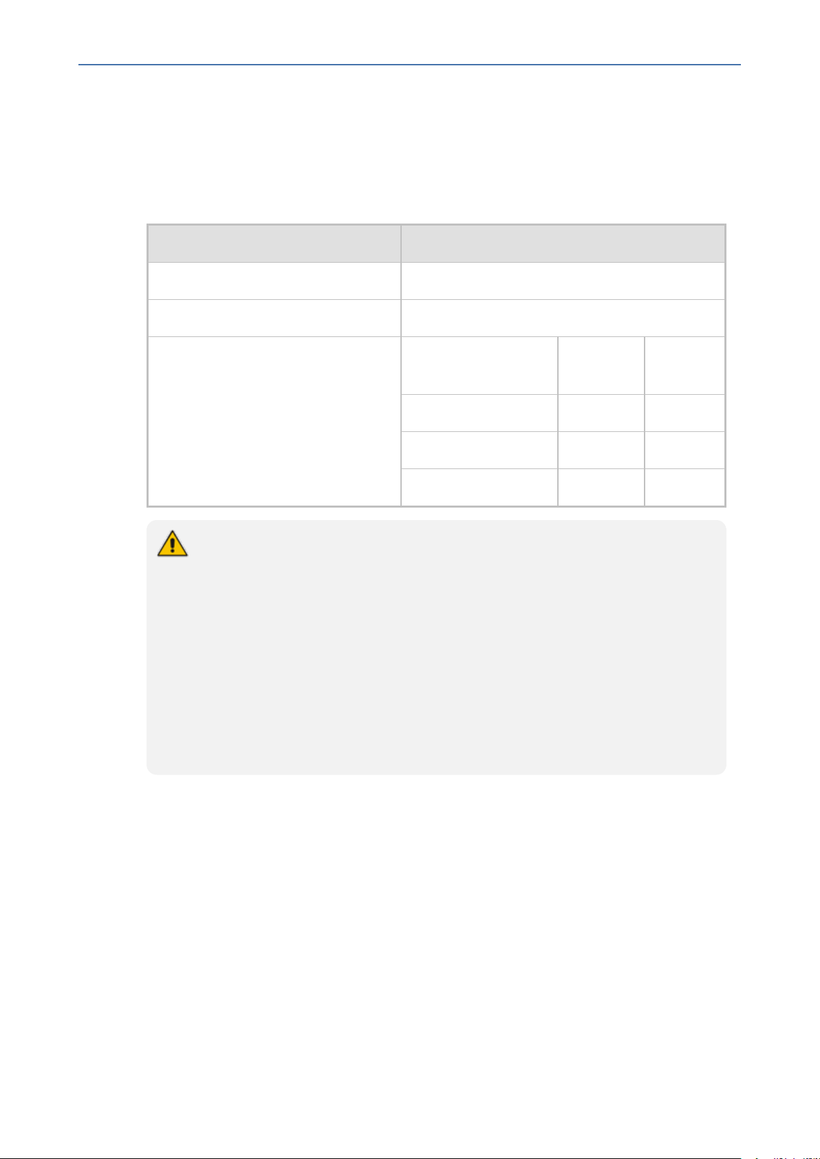
The device receives power from a standard alternating current (AC) electrical outlet. The
connection is made using the supplied AC power cord.
Physical Specification Value
MP-1288 | Hardware Installation Manual
Table 5-5: AC Power Specifications
Input Voltage Dual universal AC power supply 100-240V
AC Input Frequency 50/60 Hz
Max. AC Input Current 10 A
Max. Power Consumption FXS Interfaces Short Haul
(W)
Long Haul
(W)
288 450 950
216 400 770
144 350 600
If you are using both Power Supply modules, connect each one to a different AC power
supply source. The two AC power sources must have the same ground potential.
ご注 意
本 製 品 に 添 付 の 電 源 ケー ブ ル は、 MP- 1288
に専 用 設 計 されているため、汎 用 性 がありません. 本 電 源 ケーブルを他の機器 に使 用
されないよう、ご注 意ください.
➢ To connect the device to power:
1. Swing the cable anchor clip, located over the power inlet of the Power Supply module,
sideways, away from the power inlet to provide space for the power plug.
- 34 -
Page 41

CHAPTER5 Cabling the Device
Figure 5-19: Swinging Cable Anchor Clip away from Power Inlet
2. Plug the female end of the AC power cord (supplied) into the power inlet.
MP-1288 | Hardware Installation Manual
Figure 5-20: Connecting to Power
3. Secure the power cord to the power inlet by providing strain relief, using the cable anchor
clip. Slide the cable anchor clip sideways, towards the power inlet and then push the
power cord into the cable anchor clip, as shown in the following figure. This protects the
plug from accidentally being pulled out.
Figure 5-21: Strain Relief for Power Cord using Cable Anchor Clip
Strain relief for the power cord using the cable anchor clip is not mandatory.
4. Connect the male end of the power cord to a standard AC electrical outlet.
5. If you are using both Power Supply modules, repeat steps 1 through 3 for connecting the
second Power Supply module, but using the power socket associated with the second
Power Supply module and connecting this to a different supply circuit.
6. Turn on the power at the power source (if required).
7. Check that the LED on each Power Supply module (front panel) is lit green, indicating that
the device is receiving power. For more information on the power LED, see Power Supply
LED on page16.
- 35 -
Page 42
CHAPTER5 Cabling the Device
DC Power Supply
The device houses two hot-swappable Power Supply modules, providing 1+1 load-sharing and
power redundancy in case of a Power Supply module failure.
Physical Specification Value
Input Ratings Dual universal power supply 40-60 VDC, 32A max
Connection to DC Mains Supply Molex terminal block (supplied)
MP-1288 | Hardware Installation Manual
Table 5-6: DC Power Specifications
Max. Power Consumption
FXS Interfaces Short Haul
(W)
288 450 950
216 400 770
144 350 600
DC Power Safety Notice:
● Connect the device to a safety extra-low voltage (SELV) source that is sufficiently
isolated from the mains.
● The device must be permanently connected to earth (ground), as described in
Grounding and Surge Protection on page19.
● Connection of the device to the DC mains power must be done only by a certified
electrician and in accordance with local national electrical regulations.
● Both Power Supply modules must be connected. Ensure that you connect each
one to a different DC power supply source.
● The two DC power sources must have the same ground potential.
● If a failure occurs in any one of the Power Supply modules, replace the module
immediately.
Long Haul
(W)
The device is shipped with a DC terminal block plug for each Power Supply module. You need
to connect two 6-AWG power leads (one for positive and one for negative) to this terminal
block.
➢ To connect to a DC power supply:
1. Disconnect your DC wires from your DC power source.
2. Using a wire-stripping tool, strip the ends of the two wires (6-AWG) to a length that is
sufficient for inserting into the supplied terminal block. Make sure that you do not strip
too much of the insulation so that wire is not exposed when it exits the terminal block plug
after it has been secured to the terminal block.
- 36 -
Page 43

CHAPTER5 Cabling the Device
3. Identify the polarity (negative and positive) of the two DC power feed wires. Polarity of
power feed wires are typically color-coded, where red is positive (RTN) and black is
negative (-48VDC).
4. Insert the exposed wire of one of the two DC-input power source wires into the correct
opening (according to polarity) on the terminal block plug (supplied), as shown in the
following figure. Make sure that only wire with insulation exits the terminal block.
5. Using a Philips or flat-head screwdriver, tighten the captive screw located above the
installed wire lead to secure the wire to the terminal block.
6. Repeat steps 1 through 5 for the second wire.
Figure 5-22: Wiring DC Power Leads to Terminal Block
MP-1288 | Hardware Installation Manual
7. Make sure that no wire strands are left outside the connector and that all strands have
been clamped under the terminal block screw.
8. Gently try and pull the wires from the terminal block. Only if the wires remain secured to
the terminal block may you continue to the next step; otherwise, if the wires become free,
repeat Step 5 to secure the wires to the terminal block.
9. Insert the DC terminal block plug into the DC inlet of the Power Supply module located on
the device's rear panel. The following figure shows the completed wiring of the terminal
block.
- 37 -
Page 44

CHAPTER5 Cabling the Device
10. Connect the DC power leads to a 48-VDC power source.
MP-1288 | Hardware Installation Manual
Figure 5-23: Wired DC Power Supply Modules
- 38 -
Page 45

CHAPTER6 Hardware Maintenance
6 Hardware Maintenance
The device is designed as a modular chassis and allows you to order any module as a Field
Replacement Unit (FRU). This section describes the procedures for replacing modules.
Ensure that all unoccupied module chassis slots are covered with blank panels. This
allows optimal internal airflow pressure within the chassis.
Preventing Electrostatic Discharge Damage
Electrostatic discharge (ESD) due to improper handling of the device's modules and
components can cause irreversible damage to the equipment. Therefore, adhere to the
following guidelines for preventing ESD:
■ When handling modules, always wear a grounded ESD wrist strap or ankle strap at a
grounded work area to prevent ESD. Connect the equipment end of the strap to the
chassis' ground lug.
MP-1288 | Hardware Installation Manual
■ To prevent static electrical damage to the module, do not touch the electrical components
of the module. Instead, hold the module only on the edges where no electrical
components are located.
■ Make sure that the modules are securely installed in the chassis.
➢ To attach an ESD wrist strap to the chassis:
1. Attach the ESD wrist strap to your body (typically, the wrist) so that it is in direct contact
with your skin.
2. Attach the other end of the wrist strap (e.g., an alligator clip) to the grounding lug located
on the rear panel of the chassis. To attach a grounding lug, see Grounding and Surge
Protection on page19.
Replacing the Fan Tray Module
The following procedure describes how to replace the Fan Tray module.
● DO NOT operate the device without the Fan Tray module.
● Before replacing a failed Fan Tray module, make sure that you have the
replacement Fan Tray module on hand so that you can replace the module
immediately.
● When removing the Fan Tray module, the fan blades may still be rotating at high
speeds (even if you power off the device). Therefore, partially extract the module
from the chassis and then wait a few seconds to allow the fan blades to stop, prior
to extracting the module entirely from the chassis.
Avertissements:
- 39 -
Page 46

CHAPTER6 Hardware Maintenance
● N’opérez pas l’appareil sans module de Caisse de ventilateur ! Avant de remplacer
le module de Caisse de ventilateur, assurez-vous que vous avez le module de
remplacement en main.
● Avant de retirer le module de Caisse de ventilateur et une fois l’appareil mis hors
tension, les lames risquent de continuer à tourner à grande vitesse. Aussi,
patientez quelques secondes pour permettre aux lames de s’arrêter, avant
d’extraire le module du châssis.
➢ To replace the Fan Tray module:
1. Remove the Fan Tray module:
a. On the front panel, loosen the four Philips-head, spring-loaded captive screws located
in each corner of the Fan Tray cover, using a flat-head or Philips screwdriver:
Figure 6-1: Location of Screws on Fan Tray Cover
MP-1288 | Hardware Installation Manual
b. Remove the Fan Tray cover:
Figure 6-2: Removing Fan Tray Cover
c. Loosen the four flat-head, spring-loaded captive screws securing the Fan Tray module
to the chassis, using a flat-head screwdriver.
- 40 -
Page 47

CHAPTER6 Hardware Maintenance
Figure 6-3: Location of Screws on Fan Tray Module
d. Grip the handle of the Fan Tray module where you removed the screws in the
previous step, and then gently but firmly pull the module away from the chassis so
that it disconnects from the connector providing it with power:
Figure 6-4: Location of Handles and Removing Fan Tray Module
MP-1288 | Hardware Installation Manual
2. Install the new Fan Tray module:
a. Orientate the Fan Tray module as shown in the previous figure.
b. Grip the handles on the Fan Tray module, and then gently attach the module to the
front panel, making sure that it has engaged with the chassis backplane.
c. Secure the Fan Tray module to the chassis by tightening the four flat-head, spring-
loaded captive screws on the front panel of the module. You can use a flat-head
screwdriver.
d. Orientate the Fan Tray cover as shown in Step 1 above and then place it over the Fan
Tray module so that the screws are flush with screw holes on the handles of the Fan
Tray module. Secure the cover by tightening the four Philips-head, spring-loaded
captive screws located in each corner of the cover.
Replacing the Air Filter
The air filter is intended to prevent dust and other airborne particles from entering the chassis
and adversely affecting its components. To maintain proper operation of the device, you must
periodically replace the air filter. The frequency of replacing the air filter depends on the
cleanness at the installation site. In installation rooms with extra-building openings (exposed
to dust and/or air particles), you may need to replace the air filter once every 3 months. In
cleaner rooms (e.g., no extra-building openings), you may need to replace the air filter once
- 41 -
Page 48

CHAPTER6 Hardware Maintenance
every 6 months. In air-purified (conditioned) rooms, air filter replacement can be done
annually. It's the user's responsibility to determine the cleanness level and the air filter
replacement frequency.
● The device's components may be damaged due to a dirty or blocked air filter.
● Replace the air filter only with an air filter purchased from AudioCodes.
● Before removing the air filter, make sure that you have the replacement air filter on
hand so that you can replace it immediately.
The air filter is hot-swappable.
➢ To replace the air filter:
1. On the front panel, remove the Fan Tray cover, by loosening the four Philips-head, spring-
loaded captive screws located in each corner of the cover and then gently pulling the cover
away from the chassis:
MP-1288 | Hardware Installation Manual
Figure 6-5: Removing Fan Tray Cover on Front Panel
2. Remove the air filter cover, located on the inside of the Fan Tray cover, by removing the
two flat-head, spring-loaded captive screws located on either side of the air filter cover,
using a flathead screwdriver:
Figure 6-6: Removing Air Filter Cover from Fan Tray Cover
3. Pull out the exposed air filter from the enclosure of the air filter cover and dispose of it:
- 42 -
Page 49

CHAPTER6 Hardware Maintenance
Figure 6-7: Removing Air Filter from Air Filter Cover
4. Insert the new filter into the enclosure of the air filter cover.
5. Attach the air filter cover back on the Fan Tray cover by using the two spring-loaded
captive screws (see the figure in Step 2).
6. Attach the Fan Tray cover to the chassis (see the figure in Step 1).
MP-1288 | Hardware Installation Manual
Replacing FXS Blades
The following procedure describes how to replace an FXS blade.
Power off the device when removing or installing FXS blades.
➢ To replace an FXS blade:
1. Remove the faulty FXS blade:
a. Identify the faulty FXS blade by the color of its LED, located on the rear panel as
described in FXS LEDs on page14.
b. Power down the device, by disconnecting the power cord from the power source, and
then unplugging the power cord from the power inlet on the Power Supply module.
c. On the rear panel, disconnect the FXS cables from the 50-pin FXS ports on the FXS
blade. This is done by removing the captive screws, located on either side of the Telco
connector, from the blade's hex-standoff screws, using a flathead screwdriver:
- 43 -
Page 50

CHAPTER6 Hardware Maintenance
Figure 6-8: Removing 50-Pin Telco Connector
d. On the rear panel, remove all the hex-standoff screws securing the FXS blade to the
chassis, using a 3/16-in. hex-head nut driver. Each FXS port has two hex-standoff
screws (7 mm) on either side and therefore, you need to remove all six screws:
MP-1288 | Hardware Installation Manual
Figure 6-9: Removing Hex Standoff Screws on Rear Panel (Example FXS Blade S4)
e. On the front panel, remove the Fan Tray cover and Fan Tray module, as described in
Replacing the Fan Tray Module on page39.
f. On the front panel, loosen the two Philips-head, spring-loaded captive screws located
on either side of the FXS blade:
- 44 -
Page 51

CHAPTER6 Hardware Maintenance
Figure 6-10: Loosening Screws on FXS Blade on Front Panel
g. Gently pull the FXS blade out of the chassis slot:
MP-1288 | Hardware Installation Manual
Figure 6-11: Removing FXS Blade from Chassis Slot on Front Panel
2. Install the new FXS blade:
a. Hold the blade on the front where the captive screws are located, making sure that
you do not touch the blades electrical components.
b. On the chassis front panel, orientate the FXS blade as shown in the previous figure.
c. Gently slide the blade into the slot, keeping the left side of the blade aligned with the
left guiding rail located above the captive screw socket, and ensuring that the notch
on the underside of the blade is aligned to the left of the inner guiding rule, as shown
in the following figure. Slide the FXS blade into the slot until it has engaged with the
chassis backplane:
- 45 -
Page 52

CHAPTER6 Hardware Maintenance
Figure 6-12: Slot's Guiding Rails for FXS Blade
d. On the rear panel, secure the FXS blade to the chassis by inserting the hex-standoff
screws (see the figure in Step 1.d for location of screws), using a 3/16-in. hex-head nut
driver. Do not tighten the screws.
MP-1288 | Hardware Installation Manual
e. On the front panel, secure the FXS blade to the chassis, by tightening the two Philips-
head, captive screws on the front panel of the blade. You can use a Phillips or flathead
screwdriver.
f. On the rear panel, insert the hex-standoff screws on the FXS blade, using a 3/16-in.
hex-head nut driver.
g. On the rear panel, connect the 50-pin Telco connector cables to the FXS ports of the
new FXS blade.
h. On the front panel, re-install the Fan Tray module and Fan Tray cover, as described in
Replacing the Fan Tray Module on page39.
i. Re-connect the chassis to the power source.
Adding an FXS Blade
The following procedure describes how to add an FXS blade.
Power off the device before adding an FXS blade.
➢ To add an FXS blade:
1. Power down the device, by disconnecting the power cord from the power source, and
then unplugging the power cord from the power inlet on the Power Supply module.
2. On the rear panel, remove all three metal plates covering the slot openings for the three
50-Pin Telco connectors. To do this, insert a flat-head screwdriver into the hole of the
metal plate and carefully pry the plate off by moving the screwdriver downwards:
- 46 -
Page 53

CHAPTER6 Hardware Maintenance
Figure 6-13: Inserting Screwdriver into Cover Plate Hole
MP-1288 | Hardware Installation Manual
Figure 6-14: Removing Cover Plates
3. On the front panel, remove the Fan Tray cover and Fan Tray module, as described in
Replacing the Fan Tray Module on page39.
4. Hold the blade on its front where the captive screws are located, making sure that you do
not touch the blades electrical components.
5. On the chassis front panel, orientate the FXS blade as shown in the figure in Step 1.g in
Replacing FXS Blades on page43, and then gently slide the blade into the slot, keeping the
left side of the blade aligned with the left guiding rail located above the captive screw
socket, and ensuring that the notch on the underside of the blade is aligned to the left of
- 47 -
Page 54

CHAPTER6 Hardware Maintenance
the inner guiding rule, as shown in the following figure. Slide the FXS blade into the slot
until it has engaged with the chassis backplane:
Figure 6-15: Slot's Guiding Rails for FXS Blade
MP-1288 | Hardware Installation Manual
6. On the rear panel, secure the FXS blade to the chassis by inserting the hex-standoff
screws, using a 3/16-in. hex-head nut driver. Do not tighten the screws:
Figure 6-16: Securing FXS Blade to Chassis
7. On the front panel, secure the FXS blade to the chassis, by tightening the two Philips-head,
captive screws on the front panel of the blade. You can use a Phillips or flathead
screwdriver:
- 48 -
Page 55

CHAPTER6 Hardware Maintenance
Figure 6-17: Tightening Captive Screws of FXS Blade on Front Panel
8. On the rear panel, tighten the hex-standoff screws on each Telco connector of the FXS
blade, using a 3/16-in. hex-head nut driver.
MP-1288 | Hardware Installation Manual
9. On the front panel, re-install the Fan Tray module and Fan Tray cover, as described in
Replacing the Fan Tray Module on page39.
Replacing the CPU Module
The following procedure describes how to replace the CPU module.
Power off the device before replacing the CPU module.
➢ To replace the CPU module:
1. Power off the device.
2. Remove the faulty CPU module:
a. Power down the device by disconnecting the power cord from the power source, and
then unplugging the power cord from the power inlet on the power supply module. If
your device is installed with two power Supply modules, disconnect both of them
from the power source.
b. Remove all cables connected to the ports on the CPU module.
c. Remove the two Philips screws on both sides of the module that secure the module to
the chassis, using a Philips screwdriver.
d. Hold the front part of the module with one hand and place your other hand under the
module to support it. Gently pull the module out of the slot, keeping it at a 90-degree
angle to the backplane.
- 49 -
Page 56

CHAPTER6 Hardware Maintenance
Figure 6-18: Removing CPU Module on Rear Panel
3. Install the new CPU module:
a. Hold the front part of the module with one hand and place your other hand under the
module to support it.
b. Orientate the module as shown above and align the module with the guiding rails in
the chassis slot.
MP-1288 | Hardware Installation Manual
c. Gently slide the module into the slot until it has engaged with the chassis backplane.
d. Secure the module to the chassis, by tightening the two Philips screws on the module.
You can use a Phillips or flathead screwdriver.
e. Attach the network cables to the module.
f. Power up the device.
- 50 -
Page 57

CHAPTER6 Hardware Maintenance
Replacing Power Supply Modules
The following procedure describes how to replace a Power Supply module. The Power Supply
modules are hot-swappable. Therefore, if you are replacing only one module, you can leave
the second module connected to the power source.
The two Power Supply modules installed in the chassis must be of the same hardware
revision. You can identify the hardware revisions by the location (top or middle) of the
power LED on the front panel, as shown below:
MP-1288 | Hardware Installation Manual
➢ To replace a Power Supply module:
1. Remove the faulty Power Supply module:
a. Disconnect the Power Supply module from the power source.
◆ For AC Power: Disconnect the one end of the power cord from the power source,
by pulling the power plug out of the electrical wall outlet. Remove the plug at the
other end of the power cord from the power inlet on the Power Supply module.
◆ For DC Power: Disconnect the DC power feed cables from your DC power source.
Remove the DC terminal block from the Power Supply module.
b. While pressing inwards (sideways and to the right) on the release latch of the Power
Supply module, grip the handle of the module and gently pull the module halfway out
of the chassis slot:
- 51 -
Page 58

CHAPTER6 Hardware Maintenance
MP-1288 | Hardware Installation Manual
Figure 6-19: Handle and Release Latch on Power Supply Module (Example using AC Module)
c. Place your other hand under the Power Supply module for support and then slide it
completely out of the chassis. Avoid touching the top of the module; it may be hot
from being in the chassis:
Figure 6-20: Removing Power Supply Module from Chassis (Example using AC Module)
2. Install the new Power Supply module:
a. Grip the handle on the Power Supply module with one hand while supporting it
underneath with the other hand.
b. Orientate the Power Supply module as shown in the previous figure and align it with
the chassis slot from which you removed the faulty module.
c. Gently insert the Power Supply module into the slot until it has engaged fully with the
chassis backplane and a "click" sound heard when the release latch of the module
locks it into the slot.
d. Connect the Power Supply module to the power source.
- 52 -
Page 59

CHAPTER6 Hardware Maintenance
MP-1288 | Hardware Installation Manual
This page is intentionally left blank.
- 53 -
Page 60

International Headquarters
1 Hayarden Street,
Airport City
Lod 7019900, Israel
Tel: +972-3-976-4000
Fax: +972-3-976-4040
AudioCodes Inc.
200 Cottontail Lane
Suite A101E
Somerset NJ 08873
Tel: +1-732-469-0880
Fax: +1-732-469-2298
Contact us: https://www.audiocodes.com/corporate/offices-worldwide
Website: https://www.audiocodes.com/
Documentation Feedback: https://online.audiocodes.com/documentation-
feedback
©2020 AudioCodes Ltd. All ri ghts reserved. AudioCodes, AC, HD VoIP, HD VoIP Sounds Better, IPmedia, Mediant, MediaPack, What’s Inside Matters, OSN, SmartTAP, User Management Pack, VMAS,
VoIPerfect, VoIPerfectHD, Your Gateway T o VoIP, 3GX, VocaNom, AudioCodes One Voice, AudioCodes
Meeting Insights, AudioCodes Room E xperience and CloudBond are trademarks or registered trademarks of AudioCodes Limited. All other products or trademarks are property of thei r respective owners. Product speci fications are subject to change without notice.
Document #: LTRT-28035
 Loading...